EP0419246A2 - Video camera apparatus - Google Patents
Video camera apparatus Download PDFInfo
- Publication number
- EP0419246A2 EP0419246A2 EP90310276A EP90310276A EP0419246A2 EP 0419246 A2 EP0419246 A2 EP 0419246A2 EP 90310276 A EP90310276 A EP 90310276A EP 90310276 A EP90310276 A EP 90310276A EP 0419246 A2 EP0419246 A2 EP 0419246A2
- Authority
- EP
- European Patent Office
- Prior art keywords
- video
- video camera
- light apparatus
- video light
- remote control
- Prior art date
- Legal status (The legal status is an assumption and is not a legal conclusion. Google has not performed a legal analysis and makes no representation as to the accuracy of the status listed.)
- Granted
Links
Images


Classifications
-
- H—ELECTRICITY
- H04—ELECTRIC COMMUNICATION TECHNIQUE
- H04N—PICTORIAL COMMUNICATION, e.g. TELEVISION
- H04N23/00—Cameras or camera modules comprising electronic image sensors; Control thereof
-
- H—ELECTRICITY
- H04—ELECTRIC COMMUNICATION TECHNIQUE
- H04N—PICTORIAL COMMUNICATION, e.g. TELEVISION
- H04N23/00—Cameras or camera modules comprising electronic image sensors; Control thereof
- H04N23/60—Control of cameras or camera modules
- H04N23/65—Control of camera operation in relation to power supply
- H04N23/651—Control of camera operation in relation to power supply for reducing power consumption by affecting camera operations, e.g. sleep mode, hibernation mode or power off of selective parts of the camera
-
- H—ELECTRICITY
- H04—ELECTRIC COMMUNICATION TECHNIQUE
- H04N—PICTORIAL COMMUNICATION, e.g. TELEVISION
- H04N23/00—Cameras or camera modules comprising electronic image sensors; Control thereof
- H04N23/56—Cameras or camera modules comprising electronic image sensors; Control thereof provided with illuminating means
-
- Y—GENERAL TAGGING OF NEW TECHNOLOGICAL DEVELOPMENTS; GENERAL TAGGING OF CROSS-SECTIONAL TECHNOLOGIES SPANNING OVER SEVERAL SECTIONS OF THE IPC; TECHNICAL SUBJECTS COVERED BY FORMER USPC CROSS-REFERENCE ART COLLECTIONS [XRACs] AND DIGESTS
- Y10—TECHNICAL SUBJECTS COVERED BY FORMER USPC
- Y10S—TECHNICAL SUBJECTS COVERED BY FORMER USPC CROSS-REFERENCE ART COLLECTIONS [XRACs] AND DIGESTS
- Y10S358/00—Facsimile and static presentation processing
- Y10S358/906—Hand-held camera with recorder in a single unit
Definitions
- a video light apparatus for a video camera or a video tape recorder having a built-in type camera should include an illumination lamp which is powered or driven by a commercially-available AC voltage.
- the power requirement of such video light apparatus is high, for example 150 to 300 W, to provide high brightness lighting.
- this video light apparatus has the disadvantage that it can only be used indoors.
- a video light apparatus having one or more small batteries or dry cells incorporated therein is detachably attached to a video camera body and the video light apparatus is provided with a switch for turning its lamp ON or OFF.
- the user In this video camera apparatus, the user must operate the lamp ON/OFF switch before taking a picture with the video camera. This operation of turning ON the lamp to take a picture is cumbersome to the user.
- various operations of the video camera have to be carried out after the video light apparatus has been switched ON. Therefore, this previously proposed camera apparatus has the substantial disadvantage that the battery power is not efficiently consumed by the video camera.
- the grip 12 When the grip 12 is not attached to the bottom surface of the video camera body 1 and the standby switch 4 is turned ON in a manual fashion, the voltage from the voltage source is supplied to respective circuits within the video camera body 1, whereby the video camera apparatus is set into various kinds of modes, for example into the standby mode for picking up an image. If the user further depresses the standby switch 4, the video camera apparatus is then set into a shooting mode.
- the grip 12 When the grip 12 is attached to the video camera body 1 and the user takes a picture with the video camera body 1 by using a remote control operation portion of the grip 12, without the video light apparatus, the user inserts a plug 14a, which is provided at an end of a lead wire 14 which is connected to the grip 12, into the remote control jack 6 of the video camera body 1. Then, the user can take a picture in a zoom-up mode, in a normal mode or the like by operating the remote control operation portion of the grip 12.
- the grip 12 incorporates therein a second microcomputer also operating as a central processing unit 12a (hereinafter simply referred to as the CPU2) to control various operations of the video camera body 1 through a remote control signal.
- a second microcomputer also operating as a central processing unit 12a (hereinafter simply referred to as the CPU2) to control various operations of the video camera body 1 through a remote control signal.
- the change-over switches 7 and 8 are provided on a side wall of the housing 11 of the video light apparatus 2 as shown in Figure 2.
- a jack 13 is also provided in the side wall of the housing 11.
- a lead wire 5 from the video light apparatus 2 has a plug 5a formed at an end thereof and extends from a side wall of the housing 11, which side wall is next to the side wall of the housing 11 in which the switches 7 and 8 and the jack 13 are located.
- the plug 14a formed at the end of the lead wire 14 from the grip 12, is coupled to the jack 13 in the video light apparatus.
- the jack 13 comprises a voltage source terminal 13A, a remote control signal terminal 13B and a ground terminal 13C.
- a pair of supporting members 27a and 27b are provided on the rear surface 11c of the housing body 11a at upper and lower ends thereof so as to extend perpendicularly across the rear surface 11c to detachably hold therebetween the DC power source 3, formed as a rechargeable secondary battery. Furthermore, contact pins 30 and 31 are provided on the rear surface 11c of the housing body 11a to make electrical connection with the cathode and anode 28 and 29 (see Figure 3) of the DC power source 3.
Abstract
Description
- This invention relates to video camera apparatus. More particularly, but not exclusively, the invention is directed to a light apparatus for use with a video camera apparatus such as a video camera or a video tape recorder (VTR) having a built-in camera.
- It has previously been proposed that a video light apparatus for a video camera or a video tape recorder having a built-in type camera should include an illumination lamp which is powered or driven by a commercially-available AC voltage. The power requirement of such video light apparatus is high, for example 150 to 300 W, to provide high brightness lighting. Moreover, this video light apparatus has the disadvantage that it can only be used indoors.
- Other previously proposed video light apparatus have overcome the above-described disadvantage using a power source providing DC power in the amount of 50 W to 100 W. When the lamp of this video light apparatus is driven by DC voltage, the DC voltage is supplied from a battery pack in which many batteries are accommodated. The battery pack is heavy and the video light apparatus and the battery pack must be interconnected via a cord in order to power the video light apparatus. For this reason, it has been proposed to drive a lamp of about 5 W to 29 W with a small battery. Japanese Patent Application Publication No JP-A-62 67974 describes such previously-proposed video light apparatus.
- According to JP-A-62 67974, a video light apparatus having one or more small batteries or dry cells incorporated therein is detachably attached to a video camera body and the video light apparatus is provided with a switch for turning its lamp ON or OFF. In this video camera apparatus, the user must operate the lamp ON/OFF switch before taking a picture with the video camera. This operation of turning ON the lamp to take a picture is cumbersome to the user. Furthermore, various operations of the video camera have to be carried out after the video light apparatus has been switched ON. Therefore, this previously proposed camera apparatus has the substantial disadvantage that the battery power is not efficiently consumed by the video camera.
- According to a first aspect of the present invention there is provided a video camera apparatus in which a video light apparatus is detachably attached to a video camera body, and in which, when a standby switch of a video camera body is operated, a power switch of the video light apparatus is automatically controlled.
- According to a second aspect of the invention there is provided a video camera apparatus comprising:
a video camera body;
a video light apparatus which is detachably connected to the camera body;
a standby switch mounted to the camera body for setting a standby mode of the video camera apparatus; and
power switching means arranged in the video light apparatus for controlling the video light apparatus in response to the standby switch being set in said standby mode. - Preferred embodiments of the invention described hereinbelow provide an improved video camera apparatus which can avoid or at least reduce the aforenoted shortcomings and disadvantages encountered with the previously proposed video cameras. More specifically, by using the preferred video camera apparatus the user is free of the cumbersome operation of turning on a power switch of a video light apparatus whenever the user takes a picture. In the preferred video camera apparatus, the power of a DC voltage source can be efficiently consumed and the video light apparatus can be operated for a longer period of time.
- The invention will now be further described, by way of illustrative and non-limiting example, with reference to the accompanying drawings, in which like references are used to identify the same or similar parts throughout, and in which:
- Figure 1 is a schematic block diagram of a video camera apparatus according to a first embodiment of the invention;
- Figure 2 is an elevational view illustrating the external appearance of the video camera apparatus according to the first embodiment of the invention;
- Figure 3 is a front perspective view of a first embodiment of a video light apparatus that can be used in a video camera apparatus in accordance with the invention;
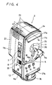
- Figure 4 is a rear perspective view of the video light apparatus of Figure 3;
- Figure 5A is an elevational view in cross section taken through a section line A-A in Figure 4;
- Figure 5B is a bottom view illustration a slide plug and control terminals of the video light apparatus as shown in Figure 5A;
- Figure 6 is a schematic diagram of a video camera apparatus according to a second embodiment of the invention; and
- Figure 7 is a schematic diagram showing an example of a DC voltage source protecting circuit that can be used in video camera apparatus in accordance with the invention.
- Figure 1 shows the circuit arrangement of a video camera apparatus according to a first embodiment of the invention, and Figure 2 shows the external appearance of the video camera apparatus, in which a
video light apparatus 2 is mounted on avideo camera body 1. - Figure 2 shows that the
video camera body 1 comprises alens 15, aviewfinder 16, aneyecup 17, and a video cassettetape compartment portion 18. Agrip 12 is detachably attached to the bottom surface of thevideo camera body 1. Astandby switch 4 is provided on a side wall of thevideo camera body 1 for placing the video camera apparatus in a standby mode. Thestandby switch 4 powers the video camera apparatus and aremote control jack 6. Although thevideo camera body 1 also includes various kinds of drive devices for setting thelens 15, for example, in a zoom-up mode, and various kinds of circuits, for the sake of simplicity the drive devices are not shown in Figure 1. - Referring to Figure 1, one
side 4A of thestandby switch 4 is coupled to aterminal 100 to which a positive voltage +B is supplied by a voltage source (not shown). Theother side 4B of thestandby switch 4 is coupled to avoltage source terminal 6A of theremote control jack 6. A remotecontrol signal terminal 6B of theremote control jack 6 is connected to amicrocomputer 4a provided in thevideo camera body 1. Thismicrocomputer 4a will hereinafter be referred to as a central processing unit (CPU1) for simplicity. TheCPU1 4a controls the ON or OFF operation of thestandby switch 4. - When the
grip 12 is not attached to the bottom surface of thevideo camera body 1 and thestandby switch 4 is turned ON in a manual fashion, the voltage from the voltage source is supplied to respective circuits within thevideo camera body 1, whereby the video camera apparatus is set into various kinds of modes, for example into the standby mode for picking up an image. If the user further depresses thestandby switch 4, the video camera apparatus is then set into a shooting mode. - When the
grip 12 is attached to thevideo camera body 1 and the user takes a picture with thevideo camera body 1 by using a remote control operation portion of thegrip 12, without the video light apparatus, the user inserts aplug 14a, which is provided at an end of alead wire 14 which is connected to thegrip 12, into theremote control jack 6 of thevideo camera body 1. Then, the user can take a picture in a zoom-up mode, in a normal mode or the like by operating the remote control operation portion of thegrip 12. Thegrip 12 incorporates therein a second microcomputer also operating as acentral processing unit 12a (hereinafter simply referred to as the CPU2) to control various operations of thevideo camera body 1 through a remote control signal. - The video camera apparatus is mainly constituted by the
video camera body 1 and thegrip 12 which effect various remote control operations as described above. In this embodiment, the video camera apparatus is additionally provided with thevideo light apparatus 2. - The
video light apparatus 2 is detachably mounted on top of thevideo camera body 1 as shown in Figure 2. Referring to Figure 2, thevideo light apparatus 2 is provided with aDC voltage source 3 formed as a rechargeable, secondary battery or the like which is detachably mounted on the rear surface of ahousing 11 of thevideo light apparatus 2. TheDC voltage source 3 will be described more fully below. - Referring back to Figure 1, an anode of the
DC voltage source 3 is connected to a movable contact 7a of a change-over switch 7 to switch the video camera apparatus between a remote control mode and a manual mode. Fixed contacts 7b and 7c of the change-overswitch 7 act as a remote control contact and an OFF contact, respectively, while a fixedcontact 7d acts as manual-ON contact of the change-overswitch 7. The fixed contact 7b of the change-overswitch 7 is connected to a movable contact 48b of aswitch 48a, which switch is automatically turned ON and OFF in response to an output signal Sd from a detectingcircuit 48. A fixed contact 48c of theswitch 48a is connected to the fixedcontact 7d of theswitch 7 and to amovable contact 8a of a lamp change-overswitch 8. A fixedcontact 8b of the lamp change-overswitch 8 is connected to a cathode of theDC voltage source 3 via a series circuit of first and secondmetal halide lamps contact 8c of the change-overswitch 8 is connected to the junction between thelamps - The change-
over switches housing 11 of thevideo light apparatus 2 as shown in Figure 2. Ajack 13 is also provided in the side wall of thehousing 11. Alead wire 5 from thevideo light apparatus 2 has aplug 5a formed at an end thereof and extends from a side wall of thehousing 11, which side wall is next to the side wall of thehousing 11 in which theswitches jack 13 are located. In this embodiment, theplug 14a, formed at the end of thelead wire 14 from thegrip 12, is coupled to thejack 13 in the video light apparatus. Thejack 13 comprises avoltage source terminal 13A, a remotecontrol signal terminal 13B and aground terminal 13C. - In the circuit arrangement shown in Figure 1, voltage from the
voltage terminals circuit 48, so that the +B voltage from the voltage source (not shown) can be detected by the detectingcircuit 48. Theswitch 48a is automatically turned ON in response to an output signal Sd from the detectingcircuit 48. When thegrip 12 is not attached to thevideo camera body 1 or when the grip remote control operation is not carried out, theplug 5a connected to the end of thelead wire 5 of the videolight apparatus 2 is inserted into thejack 6 of thevideo camera body 1. In this state, if the movable contact 7a of the change-overswitch 7 is connected to the remote control fixed contact 7b and themovable contact 8a of the change-overswitch 8 is connected to the fixedcontact 8b and thestandby switch 4 of thevideo camera body 1 is manually operated, the voltage of the internal camera voltage source (not shown) is supplied through thevoltage source terminal 6A of thejack 6 and thelead wire 5 to the detectingcircuit 48 within the videolight apparatus 2, whereby the detectingcircuit 48 detects the existence of the voltage. If the detectingcircuit 48 detects the existence of the voltage source voltage +B, the detectingcircuit 48 causes theswitch 48a to be turned ON and themovable contact 8a to be connected to the fixedcontact 8b, whereby the first and secondmetal halide lamps - If the
movable contact 8a of the change-overswitch 8 is connected to the fixedcontact 8c, then only the secondmetal halide lamp 10 is turned ON when the detectingcircuit 48 detects the +B voltage. Thus, it is possible to control the brightness of the light produced by the videolight apparatus 2. - If the video
light apparatus 2 is detached from thevideo camera body 1 to be used as a conventional flashlight and the change overswitch 7 is turned ON for the manual mode, the movable contact 7a of the change-overswitch 7 is connected to the fixedcontact 7d. Therefore, themetal halide lamps - When the
grip 12 is attached to thevideo camera body 1 to perform the grip remote control operation, theplug 14a, connected to the end of thelead wire 14 which extends from thegrip 12, must be inserted into thejack 13 of the videolight apparatus 2, and theplug 5a, connected to the end of thelead wire 5 which extends from the videolight apparatus 2, must be inserted into thejack 6 on thevideo camera body 1. Further, under this condition, if thevideo camera body 1 is placed in the standby mode by the remote control operation portion (not shown) of thegrip 12, then the remote control signal from thegrip 12 is supplied over a signal path which comprises thelead wire 14, theplug 14a, thejack 13, thelead wire 5, theplug 5a, and thejack 6, to theCPU1 4a. TheCPU1 4a then turns ON thestandby switch 4 of thevideo camera body 1. The positive voltage source voltage +B is supplied to the videolight apparatus 2 over a conductive path comprising thevoltage source terminal 100, thestandby switch 4, thevoltage source terminal 6A of thejack 6, theplug 5a, and thelead wire 5, to the detectingcircuit 48, so that the detectingcircuit 48 detects the source voltage and turns theswitch 48a ON. Furthermore, various other operations within thevideo camera body 1 can be controlled by thegrip 12 through the grip remote control operation. - The video
light apparatus 2 will now be described in more detail with reference to Figures 3 to 5B, in which Figure 3 is a front perspective view of the video light apparatus, Figure 4 is a rear perspective view of the video light apparatus, Figure 5A is a side view of a section taken along a section line A-A in Figure 4, and Figure 5B is a bottom view of a slide plug thereof. - Referring to Figures 3 to 5, the
housing 11 of the videolight apparatus 2 is formed of a synthetic resin or the like and is shaped as a rectangular box. Thehousing 11 comprises ahousing body 11a and a removable front panel orlid 11b. Underneath thefront panel 11b is a generally open space orportion 20, as shown in Figure 5A. Aframe 22 having afrosted glass 21 is engaged with thefront panel 11b and is detachably secured to thefront panel 11b so as to cover theopen space 20. Light is irradiated onto an object (not shown) from themetal halide lamps frosted glass 21 of theframe 22. - Heat
radiation slots 23 are formed through upper portions of thehousing body 11a and thefront panel 11b so as to radiate heat generated by themetal halide lamps switch 7, the lamp change-overswitch 8 and thejack 13 are provided on a right side wall of thehousing body 11a, as shown in Figure 3. If the change-overswitch 7 is moved to the remote control position, themetal halide lamps video camera body 1. Themetal halide lamps switch 8 is moved to a 10 W position, only themetal halide lamp 10 will be lit, while if theswitch 8 is moved to a 20 W position, both themetal halide lamps - The
jack 13 is supplied with the remote control signal from thegrip 12 of thevideo camera body 1 through thelead wire 14 and theplug 14a. In this form of implementation, thelead wire 5 connected to theplug 5a is led out from the left side wall of thehousing body 11a. Thelead wire 5 is inserted into aguide slot 24 formed on the rear side surface of thehousing body 11a such that thelead wire 5 is laid along theguide slot 24 so as substantially to encircle half of the left side surface, the upper surface, and the right side surface of thehousing body 11a. Further, thelead wire 5 can be inserted into aguide slot 24a (see Figure 4) formed on therear surface 11c ofhousing body 11a and theplug 5a can be inserted into aplug supporting portion 26. Thus, thelead wire 5 and plug 5a can be neatly stored. - Further, a pair of supporting
members rear surface 11c of thehousing body 11a at upper and lower ends thereof so as to extend perpendicularly across therear surface 11c to detachably hold therebetween theDC power source 3, formed as a rechargeable secondary battery. Furthermore, contact pins 30 and 31 are provided on therear surface 11c of thehousing body 11a to make electrical connection with the cathode andanode 28 and 29 (see Figure 3) of theDC power source 3. - A locating
member 32 is provided on therear surface 11c of thehousing body 11a, as shown in Figure 4, to locate theDC power source 3 correctly relative to therear surface 11a. Aslidable lever 33 is provided at the side wall of thehousing body 11a, such that when the slidable lever is moved in the direction shown by an arrow B in Figure 4 the locatingmember 32 is moved towards thehousing body 11a as shown in Figure 4 such that the end of the locatingmember 32 is flush with therear surface 11c of thehousing body 11a. In this state, if theDC power source 3 shown in Figure 3 is engaged between the supportingmembers slidable lever 33 is moved (in the direction of the arrow B′) towards theframe 22 in Figure 4, the locatingmember 32 protrudes from thehousing 11c as shown in Figure 4 and is engaged with arecess 34 formed in the front surface of theDC power source 3 as shown in Figure 3, whereby theDC power source 3 is held stably to thehousing body 11a. - A
slide plug 35 is formed on the bottom surface of thehousing body 11a of the videolight apparatus 2, as shown in Figure 5A. This slide plug 35 is inserted into a camera shoe, that is a so-calledhot shoe 19 provided on a front upper portion of thecamera body 1 as shown in Figure 2. As shown in Figure 5B, theslide plug 35 is provided with acontrol terminal 37 by which the videolight apparatus 2 is electrically connected with thevideo camera body 1. The detected signal and the control signal may be connected through thecontrol terminal 37. The camera shoe is tightly fastened to thevideo camera body 1 by rotating aknob 36 attached to the bottom portion of the videolight apparatus 2. - Within the video
light apparatus 2, a chassis 38 that is substantially U-shaped in cross-section is secured to the rear surface of thehousing body 11a as shown in Figure 5A.Sockets metal halide lamps sockets plug supporting portion 26 is shaped as a cone and is formed on the rear surface of thehousing body 11a. Theplug supporting portion 26 is projected into the chassis 38 through anopening 25 bored through the chassis 38.Light reflecting plates heat radiating plate 43 is provided on the front surface of the chassis 38 with a predetermined spacing d between thehousing body 11a and the upper surface of thefront panel 11b, whereby thehousing body 11a and thefront panel 11b, which are made of synthetic resin, are prevented from being directly heated by heat generated by themetal halide lamps heat radiating plate 43 and anupper surface portion 38a of the chassis 38. - In the above-described video camera apparatus, when the
video camera body 1 or thegrip 12 is set in the standby mode, themetal halide lamps - Figure 6 is a schematic diagram showing another embodiment of the invention. In the above-described embodiment, while the voltage from the voltage source of the
video camera body 1 is detected by the detectingcircuit 48 thereby to control the change-overswitch 48a as shown in Figure 1, another variation is also possible as shown in Figure 6. More specifically, as shown in Figure 6, a third microcomputer (hereinafter referred to as CPU3) operating as acentral processing unit 45 is provided within the videolight apparatus 2 and the CPU3 is supplied with the remote control signal and the voltage from the voltage source, from theremote control jack 6 or ahot shoe 46 on thevideo camera body 1. In this embodiment, theswitch 48a is turned ON and OFF by a control signal from theCPU3 45 provided within the videolight apparatus 2. - Figure 7 shows a DC voltage source protecting circuit which can be provided in the video
light apparatus 2. As shown in Figure 7, a batteryvoltage detecting circuit 47 is provided within the videolight apparatus 2 in order to remove a so-called memory effect in which the storage capacity is lowered by a repetitive small charge or discharge of theDC voltage source 3 formed as a secondary battery. That is, the batteryvoltage detecting circuit 47 detects the voltage across theDC voltage source 3 and, when the voltage becomes about 5V, it automatically turns OFF themetal halide lamps - In the above-described video camera apparatus, since the
metal halide lamps light apparatus 2 are automatically turned ON or OFF by operating thestandby switch 4 of thevideo camera body 1, the user is free from the cumbersome and time consuming operation of constantly turning ON the power switch when the user takes a picture and turning the power switch OFF when the camera is not in use. Further, since themetal halide lamps DC voltage source 3 from being inefficiently consumed.
Claims (9)
a video camera body (1);
a video light apparatus (2) which is detachably connected to the camera body (1);
a standby switch (4) mounted to the camera body (1) for setting a standby mode of the video camera apparatus; and
power switching means (48, 48a; 45, 48a) arranged in the video light apparatus (2) for controlling the video light apparatus (2) in response to the standby switch (4) being set in said standby mode.
a video camera body (1) provided with a standby switch (4);
a video light apparatus detachably (2) mounted to the camera body (1); and
power switching means (48, 48a; 45, 48a) responsive to operation of the standby switch (4) to control the operation of the video light apparatus (2).
Applications Claiming Priority (2)
| Application Number | Priority Date | Filing Date | Title |
|---|---|---|---|
| JP243670/89 | 1989-09-20 | ||
| JP1243670A JPH03106272A (en) | 1989-09-20 | 1989-09-20 | Video camera device |
Publications (3)
| Publication Number | Publication Date |
|---|---|
| EP0419246A2 true EP0419246A2 (en) | 1991-03-27 |
| EP0419246A3 EP0419246A3 (en) | 1992-01-22 |
| EP0419246B1 EP0419246B1 (en) | 1995-11-15 |
Family
ID=17107246
Family Applications (1)
| Application Number | Title | Priority Date | Filing Date |
|---|---|---|---|
| EP90310276A Expired - Lifetime EP0419246B1 (en) | 1989-09-20 | 1990-09-19 | Video camera apparatus |
Country Status (5)
| Country | Link |
|---|---|
| US (1) | US5073823A (en) |
| EP (1) | EP0419246B1 (en) |
| JP (1) | JPH03106272A (en) |
| KR (1) | KR100225541B1 (en) |
| DE (1) | DE69023590T2 (en) |
Cited By (2)
| Publication number | Priority date | Publication date | Assignee | Title |
|---|---|---|---|---|
| ES2224846A1 (en) * | 2003-04-28 | 2005-03-01 | Joaquin Martinez Orts | Cloth washing machine, has voice circuit connected directly to starting pulser circuits and superclarified prewashing circuits, so that prewashing is clarified with message of voice synthesized by voice circuit and by loudspeaker |
| EP1881501A1 (en) * | 2006-07-03 | 2008-01-23 | Samsung Electronics Co., Ltd. | Photographing apparatuses and method for wirelessly transmitting to and/or receiving data from other photographing apparatuses |
Families Citing this family (19)
| Publication number | Priority date | Publication date | Assignee | Title |
|---|---|---|---|---|
| JPH03157067A (en) * | 1989-11-01 | 1991-07-05 | Yuzo Tsuruta | Switching device for video camera lighting |
| KR100246211B1 (en) * | 1991-03-20 | 2000-03-15 | 이데이 노부유끼 | Video light apparatus |
| US5341171A (en) * | 1991-08-23 | 1994-08-23 | Sony Corporation | Video camera apparatus with a connecting device for easy connection with electric apparatus |
| US5508737A (en) * | 1994-07-06 | 1996-04-16 | Sony Corporation | Remote video viewing and recording system for remotely occurring events |
| US5598208A (en) * | 1994-09-26 | 1997-01-28 | Sony Corporation | Video viewing and recording system |
| US20060125918A1 (en) * | 1994-10-12 | 2006-06-15 | Camlite Corporation | Video and flashlight camera |
| JP3577817B2 (en) * | 1995-12-25 | 2004-10-20 | ソニー株式会社 | Video camera with built-in light |
| US5963255A (en) * | 1996-04-16 | 1999-10-05 | Apple Computer, Inc. | System and method for managing utilization of a battery |
| US5973734A (en) | 1997-07-09 | 1999-10-26 | Flashpoint Technology, Inc. | Method and apparatus for correcting aspect ratio in a camera graphical user interface |
| US6101339A (en) * | 1998-04-10 | 2000-08-08 | Minolta Co., Ltd. | Camera and system operating from a secondary battery |
| US6099141A (en) * | 1998-07-06 | 2000-08-08 | Sony Corporation | Roadside emergency security flashlight |
| US7602424B2 (en) | 1998-07-23 | 2009-10-13 | Scenera Technologies, Llc | Method and apparatus for automatically categorizing images in a digital camera |
| US6317141B1 (en) | 1998-12-31 | 2001-11-13 | Flashpoint Technology, Inc. | Method and apparatus for editing heterogeneous media objects in a digital imaging device |
| JP4557457B2 (en) * | 2001-04-17 | 2010-10-06 | キヤノン株式会社 | Video camera |
| US20020180866A1 (en) * | 2001-05-29 | 2002-12-05 | Monroe David A. | Modular sensor array |
| KR100518298B1 (en) * | 2003-04-30 | 2005-10-04 | 주식회사 케이티앤씨 | Apparatus and method for operating day/night mode of monitoring camera using a measuring brightness in invisible interval area |
| US9224145B1 (en) | 2006-08-30 | 2015-12-29 | Qurio Holdings, Inc. | Venue based digital rights using capture device with digital watermarking capability |
| US20110066945A1 (en) * | 2009-09-14 | 2011-03-17 | Yuk-Shan Lee | Video Greeting Cards |
| KR101582951B1 (en) * | 2014-07-18 | 2016-01-06 | 주식회사 비젼하이텍 | Optional features on CCTV waterproof removable devices |
Citations (2)
| Publication number | Priority date | Publication date | Assignee | Title |
|---|---|---|---|---|
| JPS63280578A (en) * | 1987-05-12 | 1988-11-17 | Asahi Res Kk | Controller for video camera with camera light |
| US4924246A (en) * | 1988-09-29 | 1990-05-08 | Asahi Research Corporation | Energizing system for video cameras and lights using adapter modules |
Family Cites Families (6)
| Publication number | Priority date | Publication date | Assignee | Title |
|---|---|---|---|---|
| US4531164A (en) * | 1981-02-26 | 1985-07-23 | Canon Kabushiki Kaisha | Camera and separable video recorder/reproducer arrangement |
| JPS6081979A (en) * | 1983-10-12 | 1985-05-10 | Omron Tateisi Electronics Co | Image pickup device |
| US4682238A (en) * | 1986-01-29 | 1987-07-21 | The United States Of America As Represented By The United States Department Of Energy | Energy-efficient lighting system for television |
| US4823199A (en) * | 1986-03-11 | 1989-04-18 | Minolta Camera Kabushiki Kaisha | Still video adapter device detachable to a camera body |
| US4862293A (en) * | 1986-08-30 | 1989-08-29 | Minolta Camera Kabushiki Kaisha | Still video adapter |
| US4881128A (en) * | 1988-05-11 | 1989-11-14 | Asahi Research Corporation | Video camera and recorder system with illumination control features |
-
1989
- 1989-09-20 JP JP1243670A patent/JPH03106272A/en active Pending
-
1990
- 1990-08-22 KR KR1019900012949A patent/KR100225541B1/en not_active IP Right Cessation
- 1990-09-17 US US07/583,595 patent/US5073823A/en not_active Expired - Lifetime
- 1990-09-19 EP EP90310276A patent/EP0419246B1/en not_active Expired - Lifetime
- 1990-09-19 DE DE69023590T patent/DE69023590T2/en not_active Expired - Fee Related
Patent Citations (2)
| Publication number | Priority date | Publication date | Assignee | Title |
|---|---|---|---|---|
| JPS63280578A (en) * | 1987-05-12 | 1988-11-17 | Asahi Res Kk | Controller for video camera with camera light |
| US4924246A (en) * | 1988-09-29 | 1990-05-08 | Asahi Research Corporation | Energizing system for video cameras and lights using adapter modules |
Non-Patent Citations (1)
| Title |
|---|
| PATENT ABSTRACTS OF JAPAN, vol. 13, no. 109 (E-727)[3457], 15th March 1989; & JP-A-63 280 578 (ASAHI RES. K.K.) 17-11-1988 * |
Cited By (2)
| Publication number | Priority date | Publication date | Assignee | Title |
|---|---|---|---|---|
| ES2224846A1 (en) * | 2003-04-28 | 2005-03-01 | Joaquin Martinez Orts | Cloth washing machine, has voice circuit connected directly to starting pulser circuits and superclarified prewashing circuits, so that prewashing is clarified with message of voice synthesized by voice circuit and by loudspeaker |
| EP1881501A1 (en) * | 2006-07-03 | 2008-01-23 | Samsung Electronics Co., Ltd. | Photographing apparatuses and method for wirelessly transmitting to and/or receiving data from other photographing apparatuses |
Also Published As
| Publication number | Publication date |
|---|---|
| US5073823A (en) | 1991-12-17 |
| JPH03106272A (en) | 1991-05-02 |
| DE69023590D1 (en) | 1995-12-21 |
| EP0419246B1 (en) | 1995-11-15 |
| KR100225541B1 (en) | 1999-10-15 |
| DE69023590T2 (en) | 1996-04-18 |
| EP0419246A3 (en) | 1992-01-22 |
| KR910007341A (en) | 1991-04-30 |
Similar Documents
| Publication | Publication Date | Title |
|---|---|---|
| EP0419246B1 (en) | Video camera apparatus | |
| EP0449657B1 (en) | Video camera | |
| US5259786A (en) | Lamp unit battery seat | |
| CN1264191A (en) | Jumper cable | |
| US20070273326A1 (en) | Charger with internal battery for charging portable batteries | |
| US5459389A (en) | Dual-charging system for a portable electric appliance | |
| US4106077A (en) | Top mounted photoflash attachment for cameras with self-developing film | |
| GB2260040A (en) | Battery charger | |
| US5036343A (en) | Camera with side-mounted balancer | |
| JPH11289367A (en) | Telephone set indlucing storage battery and the storage battery suitable for telephone set | |
| US5075706A (en) | Accessory shoe adapter for video camera | |
| US20040076875A1 (en) | Adjustable auxiliary camera power pack | |
| US3782814A (en) | Rechargeable battery pack for portable camera | |
| US4592635A (en) | Power handle for electronic flash unit and remote shutter release device | |
| US3798439A (en) | Illumination and other devices for use with photographic film pack container | |
| US20080095525A1 (en) | Adjustable auxiliary camera power pack | |
| KR960007245B1 (en) | Battery coupler | |
| US5119008A (en) | Battery charging apparatus | |
| EP0505287B1 (en) | Video light apparatus for video cameras | |
| JP3802077B2 (en) | Automatic flasher | |
| CN215419630U (en) | Multifunctional device with functions of mobile power supply and flashlight | |
| US4355876A (en) | Control device having an internal electric or voltage source | |
| JP3089703B2 (en) | Video camera battery charger | |
| CN219351308U (en) | Energy storage device, equipment to be charged and energy storage system | |
| JPH11176405A (en) | Instrument using battery pack |
Legal Events
| Date | Code | Title | Description |
|---|---|---|---|
| PUAI | Public reference made under article 153(3) epc to a published international application that has entered the european phase |
Free format text: ORIGINAL CODE: 0009012 |
|
| AK | Designated contracting states |
Kind code of ref document: A2 Designated state(s): DE FR GB |
|
| PUAL | Search report despatched |
Free format text: ORIGINAL CODE: 0009013 |
|
| AK | Designated contracting states |
Kind code of ref document: A3 Designated state(s): DE FR GB |
|
| 17P | Request for examination filed |
Effective date: 19920618 |
|
| 17Q | First examination report despatched |
Effective date: 19940331 |
|
| GRAA | (expected) grant |
Free format text: ORIGINAL CODE: 0009210 |
|
| AK | Designated contracting states |
Kind code of ref document: B1 Designated state(s): DE FR GB |
|
| REF | Corresponds to: |
Ref document number: 69023590 Country of ref document: DE Date of ref document: 19951221 |
|
| ET | Fr: translation filed | ||
| PLBE | No opposition filed within time limit |
Free format text: ORIGINAL CODE: 0009261 |
|
| STAA | Information on the status of an ep patent application or granted ep patent |
Free format text: STATUS: NO OPPOSITION FILED WITHIN TIME LIMIT |
|
| 26N | No opposition filed | ||
| PGFP | Annual fee paid to national office [announced via postgrant information from national office to epo] |
Ref country code: FR Payment date: 20010911 Year of fee payment: 12 |
|
| PGFP | Annual fee paid to national office [announced via postgrant information from national office to epo] |
Ref country code: GB Payment date: 20010919 Year of fee payment: 12 |
|
| PGFP | Annual fee paid to national office [announced via postgrant information from national office to epo] |
Ref country code: DE Payment date: 20011001 Year of fee payment: 12 |
|
| REG | Reference to a national code |
Ref country code: GB Ref legal event code: IF02 |
|
| PG25 | Lapsed in a contracting state [announced via postgrant information from national office to epo] |
Ref country code: GB Free format text: LAPSE BECAUSE OF NON-PAYMENT OF DUE FEES Effective date: 20020919 |
|
| PG25 | Lapsed in a contracting state [announced via postgrant information from national office to epo] |
Ref country code: DE Free format text: LAPSE BECAUSE OF NON-PAYMENT OF DUE FEES Effective date: 20030401 |
|
| GBPC | Gb: european patent ceased through non-payment of renewal fee |
Effective date: 20020919 |
|
| PG25 | Lapsed in a contracting state [announced via postgrant information from national office to epo] |
Ref country code: FR Free format text: LAPSE BECAUSE OF NON-PAYMENT OF DUE FEES Effective date: 20030603 |
|
| REG | Reference to a national code |
Ref country code: FR Ref legal event code: ST |