EP0418865A2 - Wireless signal transmission system with random access - Google Patents
Wireless signal transmission system with random access Download PDFInfo
- Publication number
- EP0418865A2 EP0418865A2 EP19900118036 EP90118036A EP0418865A2 EP 0418865 A2 EP0418865 A2 EP 0418865A2 EP 19900118036 EP19900118036 EP 19900118036 EP 90118036 A EP90118036 A EP 90118036A EP 0418865 A2 EP0418865 A2 EP 0418865A2
- Authority
- EP
- European Patent Office
- Prior art keywords
- signal
- data
- central station
- transmission
- terminal stations
- Prior art date
- Legal status (The legal status is an assumption and is not a legal conclusion. Google has not performed a legal analysis and makes no representation as to the accuracy of the status listed.)
- Granted
Links
Images


Classifications
-
- H—ELECTRICITY
- H04—ELECTRIC COMMUNICATION TECHNIQUE
- H04W—WIRELESS COMMUNICATION NETWORKS
- H04W74/00—Wireless channel access, e.g. scheduled or random access
- H04W74/002—Transmission of channel access control information
- H04W74/004—Transmission of channel access control information in the uplink, i.e. towards network
-
- H—ELECTRICITY
- H04—ELECTRIC COMMUNICATION TECHNIQUE
- H04W—WIRELESS COMMUNICATION NETWORKS
- H04W74/00—Wireless channel access, e.g. scheduled or random access
- H04W74/08—Non-scheduled or contention based access, e.g. random access, ALOHA, CSMA [Carrier Sense Multiple Access]
- H04W74/0833—Non-scheduled or contention based access, e.g. random access, ALOHA, CSMA [Carrier Sense Multiple Access] using a random access procedure
-
- H—ELECTRICITY
- H04—ELECTRIC COMMUNICATION TECHNIQUE
- H04L—TRANSMISSION OF DIGITAL INFORMATION, e.g. TELEGRAPHIC COMMUNICATION
- H04L1/00—Arrangements for detecting or preventing errors in the information received
- H04L1/12—Arrangements for detecting or preventing errors in the information received by using return channel
- H04L1/16—Arrangements for detecting or preventing errors in the information received by using return channel in which the return channel carries supervisory signals, e.g. repetition request signals
- H04L1/18—Automatic repetition systems, e.g. Van Duuren systems
- H04L1/1867—Arrangements specially adapted for the transmitter end
- H04L1/1887—Scheduling and prioritising arrangements
-
- H—ELECTRICITY
- H04—ELECTRIC COMMUNICATION TECHNIQUE
- H04W—WIRELESS COMMUNICATION NETWORKS
- H04W72/00—Local resource management
- H04W72/20—Control channels or signalling for resource management
-
- H—ELECTRICITY
- H04—ELECTRIC COMMUNICATION TECHNIQUE
- H04W—WIRELESS COMMUNICATION NETWORKS
- H04W72/00—Local resource management
- H04W72/50—Allocation or scheduling criteria for wireless resources
- H04W72/52—Allocation or scheduling criteria for wireless resources based on load
-
- H—ELECTRICITY
- H04—ELECTRIC COMMUNICATION TECHNIQUE
- H04W—WIRELESS COMMUNICATION NETWORKS
- H04W74/00—Wireless channel access, e.g. scheduled or random access
- H04W74/002—Transmission of channel access control information
- H04W74/006—Transmission of channel access control information in the downlink, i.e. towards the terminal
Definitions
- the present invention generally relates to a wireless signal transmission systems and particularly to a wireless signal transmission system in which a plurality of terminal stations make access to a central station at random, thereby to transmit signals thereto.
- the slotted ALOHA system and the ICMA (Idle Signal Casting Multiple Access) system are known, in which a plurality of terminal stations access the central station at random.
- the ICMA system is particularly advantageous, if a long signal is to be transmitted.
- signals are transmitted through the upward links to such extent that the signal collision rate exceeds, for example, 0.2, and the reliability of the system is ensured by re-transmitting the signals.
- the LAPB is equivalent to the balanced HDLC (high level data link control) transmission system.
- the word "balanced" means that a transmission terminal and a reception terminal are on an equal footing.
- a transmitting station transmits a signal including 16-bit check codes to a receiving station. If the receiving station detects an error in the signal, it output a re-transmission request to the transmitting station, requesting that the transmitting station re-transmit the signal. More specifically, re-transmission control is performed, wherein the transmitting station re-transmits the message, and the receiving station supplies, upon receipt of the re-transmitted message, a layer-2 acknowledge signal to the transmitting station, thus acknowledging the receipt of the message. The reliability of the HDLC system is thereby ensured.
- Fig. 6 shows a signal structure according to the conventional LAPB format.
- a signal to be transmitted contains a frame synchronizing flag F, a control code C, transmission data D, and a check code CRC.
- the check code CRC is comprised of bits and obtained by a specific generation polynomial equation.
- the check code CRC is added to data (C+D).
- the receiving station detects an error in the data (C+D+CRC) received, and transmits a control code C to the transmission terminal, informing whether or not the signal has been correctly received. If NO, the transmitting station re-transmits the signal to the receiving station.
- the central station does not receive the signal within a predetermined period of time, it re-transmits the massage to the terminal station through the downward link. Obviously, this results in a low transmission efficiency and a great transmission delay, particularly when the message is long.
- an object of the present invention to provide a new and improved wireless signal transmission system with random access, in which an effective data transmission is achieved by use of the LAPB or layer-2 procedure of a protocol as an extended LAPB, and general-purpose data transmission is achieved by use of the known layer-2 procedure or the extended layer-2 procedure.
- a central station generates data in accordance with a predetermined rule based on a signal transmitted from a terminal station.
- This data includes, for example, part of the signal, an identification number of the terminal station, or the results of the predetermined logical operation using the data and the identification number.
- the central station transmits the data to the terminal station.
- the terminal station compares this data with data which is generated in accordance with the same rule as the predetermined rule at the central station, based on data restored in the terminal station, determines whether or not the central station has correctly received the signal from the terminal station. If NO, the terminal station suspends the signal transmission for a predetermined period of time.
- a digital wireless communication method for transferring data between a plurality of terminal stations and a central station with random access, the method comprising the steps of: generating and transmitting, in the central station, data in accordance with a predetermined rule based on a signal transmitted from one of the terminal stations; comparing, in the one terminal station which have been transmitted the signal the data from the central station with data restored in the one of terminal stations, after the original transmission starting; determining whether or not the central station has correctly received the signal from the one terminal station; and suspending transmission of signals from the one of the terminal stations, for a predetermined period of time if the resultant by the determining step is not correct.
- a mobile digital communication method for transferring data between a plurality of terminal stations and a central station, the method comprising the steps of: preparing and transmitting, in the central station, data of a transmission format including an I/B bit indicating permission or inhibition of a new transmission at a next transmission timing of the terminal stations, an R/N bit indicating reception or non-reception of signals from the terminal stations at the central station, and partial data produced from data received at the central station in accordance with a predetermined rule based on the signals which the central station received from the terminal stations; preparing signal-length data W to the transmission format in the terminal stations, the signal-length data W representing the length of a signal to be transmitted from each terminal station; starting the new transmission of the signal or signals containing the signal-length data W, from one or plural of the terminal stations to the central station when the I/B bit indicates the permission of the new transmission; determining and transmitting, in the central device, the I/B bit, the R/
- a mobile digital communication system for transferring data, in random access, between a plurality of terminal stations and a central station, the system comprising the steps of: means for preparing and transferring, in the central station, data of a transmission format including an I/B bit indicating permission or inhibition of a new transmission of a next transmission timing of the terminal stations, an R/N bit indicating reception or non-reception of signals from the terminal stations at the central station, and partial data produced from data received at the central station in accordance with a predetermined rule based on the signals which the central station received from the terminal stations; means for preparing signal-length data W to the transmission format in the terminal stations, the signal-length data W representing the length of a signal to be transmitted from each terminal station; means for starting the new transmission of the signal or signals containing the signal-length data W, from one or plural of the terminal stations to the central station, when the I/B bit indicates the permission of the new transmission; means for determining and transmit
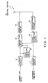
- Fig. 1 is a block diagram showing one of the terminal stations incorporated in a digital mobile communication system according to this invention.
- the terminal station comprises an encoding circuit 11, a logic operation circuit 12, a transmitting circuit 13, a modulating circuit 14, a demodulating circuit 15, an signal extraction circuit 16, and a decoding circuit 17.
- Fig. 2 is a block diagram illustrating the central station of the digital mobile communications system.
- the central station comprises a demodulating circuit 21, a signal extraction circuit 22, a decoding circuit 23, a logic operation circuit 24, an indication control circuit 25, an encoding circuit 26, a signal-multiplexing circuit 27, and a modulating circuit 28.
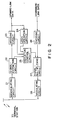
- Fig. 3 illustrates the format of a signal transmitted through the downward link of the system.
- the signal consists of units, each comprised of a first slot (S1) 31, a second slot (S2) 32, and a third slot (S3) 33.
- Each slot has a frame synchronization word 34, an indication signal 35, and data 36.
- check bits (not shown) are set at the end of the signal format.
- Each indication signal 35 consists of data 37 pertaining to permission for a new transmission of the terminal station at a next transmission timing of the terminal station, and part of the signal transferred from the terminal station.
- the data 37 is "I” to permit the transmission of a signal; it is “B” to inhibit the transmission of the signal.
- the data 38 is "R” to inform the correctly reception of a signal; it is “N” to inform the incorrectly reception or non-reception of the signal.
- Fig. 4 represents the format of a signal transmitted through the upward link of the system according to the embodiment of the invention.
- the signal consists of units, each comprised of a first slot (S1) 31, a second slot (S2) 32, and a third slot (S3) 33.
- Also shown in Fig. 4 are upward link burst signals 41 con-tained in specific slots, i.e., the second slots S2.
- Each upward link burst signal consists of a synchronization signal 42, a frame synchronizing signal 43, and upward link data 45.
- the signal 41 shown leftmost in Fig. 4, contains data 44 (typically the signal length W of a transmitting signal) pertaining to the structure of a message.
- the signal format is a sequence of slots of various kinds, and random access control which provides for the I/B data is utilized for each slot.
- the upward link data is divided into a plurality of bursts for transmission in a number required by the length of the message.
- the first burst contains, as shown in Fig. 4, data 44 pertaining to the structure of the message and also the number of bursts constituting that message.
- the down I/B data 37 indicates wither transmission permitted or transmission inhibited, in accordance with the number of the bursts W, thereby protecting a signal being transmitted from one terminal station against collision with signals being transmitted from the other terminal stations.
- B is set for the two consecutive slots that are assigned for use by the terminal station.
- a bit synchronization signal of a second burst is shorter than that of the first burst since the second burst is received after bit synchronization has been established in the first burst and retained, and a large field is provided for the upward link data by omission of the information pertaining to the signal structure.
- the encoding circuit 11 encodes the message, thus forming, for example, error correcting codes.
- the message is then input to the transmitting circuit 13, so that it can be transmitted to the central station.
- Partial data resulting from fixed initial processing is input to the transmitting circuit 13 and stored therein. (The partial data is that part (e.g., the first 10 bits or the last 10 bits of the upward information bits) of the upward link data to be transmitted.)
- the data is demodulated by the demodulation circuit 15 is supplied to the transmission control circuit 13 after the indication signal 35 (Fig. 3) has been separated by the signal extraction circuit 16.
- the I/B data indicates permission (I)
- transmission is commenced from the first burst in the next slot timing.
- the central station receives the burst signal.
- the demodulating circuit 21 demodulates the burst signal, and the signal extraction circuit 22 processes the demodulated signal.
- the data representing the number of the message-constituting bursts contained in the first burst is input to the indication control circuit 25.
- the decoding circuit 23 decodes the upward link data, thereby correcting errors, etc.
- the upward link data, thus decoded is input to the logic opera-tion circuit 24, whereas the partial data resulting from the same processing performed in the logic operation circuit 12 of the terminal station is input to the indication control circuit 25, thus taking out the partial data received.
- the decoding circuit 23 detects errors and supplies a signal to the indication control circuit 25, informing whether or not the signal has been received.
- the indication control circuit 25 sets bits 37, thereby permitting or inhibiting transmission in accordance with the value of W, and also sets bit of the R/N data, thus informing whether or not the signal has been received. If the bit is "R,” it indicates that the signal has been received. If the bit is "N,” it indicates that the signal has not been received.
- the partial data so taken out is incorporated into the indication signal 35.
- the indication signal 35 is transmitted via the signal-multiplexing circuit 27 and modulation circuit 28.
- the indication signal 35 is supplied to the transmitting circuit 13 through the demodulation circuit 15 and the signal extraction circuit 16. If the R/N information 38 output by the signal extraction circuit 16 is "R,” indicating the receipt of the transmitted data, the transmitting circuit 13 compares the partial data 39 with that one stored in the logic operation circuit 12 prior to the transmission. If the compared data pieces are identical, the circuit 13 determines that the data transmitted has been correctly received, and transmits the next burst. Alternatively, the circuit 13 stops transmitting the next burst if the message is short and requires only one burst.
- the transmitting circuit 13 When the R/N information 38 indicates non-reception, or when the partial data 39 is not identical to the stored partial data, the transmitting circuit 13 is held in a waiting state for re-transmitting the data from the first burst. Immediately, or upon lapse of a period of time, the circuit 13 starts again to transmit the data when the bit 37 indicates the transmission permitted.
- Fig. 5 is a diagram explaining the operation of the system according to the the invention.
- the two message signals are simultaneously transmitted at time A in response to instructions of transmission-permitted (I) and a collision occurs between the two message signals.
- the central station transmits a signal, in the next slot, to the the surviving terminal station, informing that the transmission has been permitted and that the partial data has been received.
- the terminal station 2 stops transmitting the message since the partial data is identical to the stored one, while the terminal station 1 is held in the waiting state for re-transmission due to non-coincidence. If re-transmission takes place at time B, and the re-transmitted signal collides with a signal from a terminal station 3, and if either signal reaches the terminal station 1, the terminal station 1 is again brought into the waiting state since transmission permitted, non-reception of signal (N), and the receipt of the partial data (X) are notified in the next slot. The terminal section 2 therefore re-transmit data at time C.
- the terminal station receives, in the next slot, a signal indicating transmission permitted (I), signal received (R), and partial data received (1).
- the coincidence of the transmitted data with the stored causes the terminal station 1 to complete transmission of the message "1 a b c".
- the invention provides a high degree of reliability of up signals to permit bi-directional information transmission to be effectively performed by utilizing a fixed layer 2 procedure.
- the partial data may be produced by directly subjecting the received data to logic operation processing without correcting an error.
- the partial data can be provided by taking out a part of the bit array of the message in 10 bits or so, as described above, but may also be by taking out 10 bits or so from appropriate plural points of the bit array of the upward link data 45 and by adding the bits or Ex-ORing each bit.
- the transmission of down-data is more effective than the random-access transmission of upward link data. Therefore, to assign 30% or so of a down information field to the partial data does not create any particular problem in attaining well balanced bi-directional information transfer.
- Comparison of partial data with another one may be effected not only for detecting coincidence of data to the fullest extent, but may utilize a technique allowing an error in one bit or so considering a transmission error. Although allowing an error necessarily increases the probability in which partial data from two different terminals come to be casually coincident with each other, the probability of coincidence that can happen by allowing a one bit error to remain, for example, in a 14 bits partial data is on the order of 10 ⁇ 4 and is still tolerable.
- the foregoing description is limited to the arrangement in which three transmitting slots at the terminal stations are placed one slot after the receiving slot, thus enabling the terminal station to identify the partial data before this station receives the next slot.
- the value W can independently decoded in the head portion of the burst, and the signal indicating either transmission permitted or transmission inhibited can be set in the end portion of the burst. Then, the partial data will be transmitted with a delay of one-cycle time.
- the technique of determining whether or not a signal has been received at the central station has been described by way of detecting an error, the level of the data received or the results of lower-level identification of data can be used for this purpose.
- the indication of the transmission status has been described as giving information respecting only reception or non-reception, such information may validly include the nature of non-reception (for example, non-reception due to thermal noise when the reception level is low; non-reception due to signal collision when the reception level is high but a coding error exists), so that re-transmission may be instructed depending upon the nature of the error.
- immediate re-transmission may be instructed, while in the case of non-reception due to collision, re-transmission may take place after the lapse of a random time delay to avoid re-collision.
- the bits 38 (Fig. 3) representing a reception or non-reception of data may occupy a common field with the bits 39 for partial data.
- partial data is unnecessary in the case of non-reception.
- a field formed by combining the bits 38 indicating reception or non-reception and the bits 39 assigned for partial data can be used to express a specific pattern (e.g., all-one bits) in order to show non-reception, and this same field may be used in receiving partial data.
- a specific pattern e.g., all-one bits
- the partial data is identical to a specific pattern, several of the pattern bits may be forcedly processed, such as by inverting the first three bits.
- the partial data can still be reproduced from the data merely decoded from the noise, without determining whether or not the data has been received, for example, by omitting the bits representing reception/non-reception of data.
- Reference to the partial data provides correct judgment on the reception and non-reception of data with high accuracy.
- regions of high throughput are used in this invention, so that the reliability of up-signals is high in situations where probability of collision is relatively high, with the result that bi-direction data-transmission can be achieved by use of the fixed layer-2 procedure.
Abstract
Description
- The present invention generally relates to a wireless signal transmission systems and particularly to a wireless signal transmission system in which a plurality of terminal stations make access to a central station at random, thereby to transmit signals thereto.
- The slotted ALOHA system and the ICMA (Idle Signal Casting Multiple Access) system are known, in which a plurality of terminal stations access the central station at random. The ICMA system is particularly advantageous, if a long signal is to be transmitted.
- However, when the LAPB (described later) or specific layer-2 procedure of protocol such as extended LAPB is employed in these conventional communication systems, the systems will have a very low transmission efficiency. This is because signal transmission though the upward links is limited due to signal collision, though data transmission through the upward links needs to be balanced with the data transmission through the downward links.
- To obtain a good throughput characteristic of a random access system, signals are transmitted through the upward links to such extent that the signal collision rate exceeds, for example, 0.2, and the reliability of the system is ensured by re-transmitting the signals.
- The LAPB is equivalent to the balanced HDLC (high level data link control) transmission system. The word "balanced" means that a transmission terminal and a reception terminal are on an equal footing.
- In the HDLC system, a transmitting station transmits a signal including 16-bit check codes to a receiving station. If the receiving station detects an error in the signal, it output a re-transmission request to the transmitting station, requesting that the transmitting station re-transmit the signal. More specifically, re-transmission control is performed, wherein the transmitting station re-transmits the message, and the receiving station supplies, upon receipt of the re-transmitted message, a layer-2 acknowledge signal to the transmitting station, thus acknowledging the receipt of the message. The reliability of the HDLC system is thereby ensured.
- Fig. 6 shows a signal structure according to the conventional LAPB format. As is shown in this figure, a signal to be transmitted contains a frame synchronizing flag F, a control code C, transmission data D, and a check code CRC. The check code CRC is comprised of bits and obtained by a specific generation polynomial equation. The check code CRC is added to data (C+D). The receiving station detects an error in the data (C+D+CRC) received, and transmits a control code C to the transmission terminal, informing whether or not the signal has been correctly received. If NO, the transmitting station re-transmits the signal to the receiving station.
- When the above-described communication procedure is applied to random access in a mobile digital communication, especially when the central station transmits a massage through a downward link to a terminal station, and the terminal station transmits, upon receipt of the message, a layer-2 acknowledge signal through the upward link at random the central station, the acknowledge signal collides another signal in another upward link at high probability. Consequently, the signal may not reach the central station.
- If the the central station does not receive the signal within a predetermined period of time, it re-transmits the massage to the terminal station through the downward link. Obviously, this results in a low transmission efficiency and a great transmission delay, particularly when the message is long.
- It is, therefore, an object of the present invention to provide a new and improved wireless signal transmission system with random access, in which an effective data transmission is achieved by use of the LAPB or layer-2 procedure of a protocol as an extended LAPB, and general-purpose data transmission is achieved by use of the known layer-2 procedure or the extended layer-2 procedure.
- To achieve the object, a central station generates data in accordance with a predetermined rule based on a signal transmitted from a terminal station. (This data includes, for example, part of the signal, an identification number of the terminal station, or the results of the predetermined logical operation using the data and the identification number.) The central station transmits the data to the terminal station. The terminal station compares this data with data which is generated in accordance with the same rule as the predetermined rule at the central station, based on data restored in the terminal station, determines whether or not the central station has correctly received the signal from the terminal station. If NO, the terminal station suspends the signal transmission for a predetermined period of time.
- According to a first aspect of the invention, there is provided a digital wireless communication method for transferring data between a plurality of terminal stations and a central station with random access, the method comprising the steps of: generating and transmitting, in the central station, data in accordance with a predetermined rule based on a signal transmitted from one of the terminal stations; comparing, in the one terminal station which have been transmitted the signal the data from the central station with data restored in the one of terminal stations, after the original transmission starting; determining whether or not the central station has correctly received the signal from the one terminal station; and suspending transmission of signals from the one of the terminal stations, for a predetermined period of time if the resultant by the determining step is not correct.
- According to a second aspect of the invention, there is provided a mobile digital communication method for transferring data between a plurality of terminal stations and a central station, the method comprising the steps of: preparing and transmitting, in the central station, data of a transmission format including an I/B bit indicating permission or inhibition of a new transmission at a next transmission timing of the terminal stations, an R/N bit indicating reception or non-reception of signals from the terminal stations at the central station, and partial data produced from data received at the central station in accordance with a predetermined rule based on the signals which the central station received from the terminal stations; preparing signal-length data W to the transmission format in the terminal stations, the signal-length data W representing the length of a signal to be transmitted from each terminal station; starting the new transmission of the signal or signals containing the signal-length data W, from one or plural of the terminal stations to the central station when the I/B bit indicates the permission of the new transmission; determining and transmitting, in the central device, the I/B bit, the R/N bit, and the partial data in accordance with the reception of the signal-length data W and the signal transmitted from one of the terminal stations; determining, in the one or plural of the terminal stations which have been transmitted, whether or not the signal has been correctly received at the central station, in accordance with the R/N bit and the partial data from the central station; and suspending transmission of signals from the one or plural of the terminal stations, for a predetermined period of time, when it is determined that the signal has not been correctly received at the central station.
- According to a third aspect of the invention, there is provided a mobile digital communication system for transferring data, in random access, between a plurality of terminal stations and a central station, the system comprising the steps of: means for preparing and transferring, in the central station, data of a transmission format including an I/B bit indicating permission or inhibition of a new transmission of a next transmission timing of the terminal stations, an R/N bit indicating reception or non-reception of signals from the terminal stations at the central station, and partial data produced from data received at the central station in accordance with a predetermined rule based on the signals which the central station received from the terminal stations; means for preparing signal-length data W to the transmission format in the terminal stations, the signal-length data W representing the length of a signal to be transmitted from each terminal station; means for starting the new transmission of the signal or signals containing the signal-length data W, from one or plural of the terminal stations to the central station, when the I/B bit indicates the permission of the new transmission; means for determining and transmitting, in the central station, the I/B bit, the R/N bit, and the partial data in accordance with the reception of the signal-length data W and the signal transmitted from one of the terminal stations; means for determining, in the one or plural of the terminal station which have been transmitted, whether or not a signal has been correctly received at the central station, in accordance with the R/N bit and the partial data; and means for suspending transmission of signals from the one or plural of the terminal stations, for a predetermined period of time, when it is determined that the signal has not been correctly received at the central station.
- This invention can be more fully understood from the following detailed description when taken in conjunction with the accompanying drawings, in which:
- Fig. 1 is a diagram illustrating a terminal station incorporated in a system according to the present invention;
- Fig. 2 is a diagram showing the central station incorporated in the system according to the present invention;
- Fig. 3 is a diagram representing the format of a signal transmitted through the downward link of the system;
- Fig. 4 is a diagram representing the format of a signal transmitted through the upward link of the system;
- Fig. 5 is a diagram explaining the operation of the system according to the invention; and
- Fig. 6 is a diagram illustrating the format of a signal transmitted in the conventional LAPB system.
- Reference will now be made in detail to the presently preferred embodiment of the invention as illustrated in the accompanying drawings, in which like reference characters designate like or corresponding parts throughout the several drawings.
- Fig. 1 is a block diagram showing one of the terminal stations incorporated in a digital mobile communication system according to this invention. As is shown in Fig. 1, the terminal station comprises an encoding circuit 11, a logic operation circuit 12, a
transmitting circuit 13, a modulatingcircuit 14, ademodulating circuit 15, ansignal extraction circuit 16, and adecoding circuit 17. - Fig. 2 is a block diagram illustrating the central station of the digital mobile communications system. As is shown in Fig. 2, the central station comprises a
demodulating circuit 21, asignal extraction circuit 22, adecoding circuit 23, alogic operation circuit 24, anindication control circuit 25, anencoding circuit 26, a signal-multiplexing circuit 27, and a modulatingcircuit 28. - Fig. 3 illustrates the format of a signal transmitted through the downward link of the system. As this figure shows, the signal consists of units, each comprised of a first slot (S1) 31, a second slot (S2) 32, and a third slot (S3) 33. Each slot has a
frame synchronization word 34, anindication signal 35, anddata 36. To perform error control, check bits (not shown) are set at the end of the signal format. Eachindication signal 35 consists ofdata 37 pertaining to permission for a new transmission of the terminal station at a next transmission timing of the terminal station, and part of the signal transferred from the terminal station. Thedata 37 is "I" to permit the transmission of a signal; it is "B" to inhibit the transmission of the signal. Thedata 38 is "R" to inform the correctly reception of a signal; it is "N" to inform the incorrectly reception or non-reception of the signal. There are several techniques available for generating thepartial data 39, which will be described later. - Fig. 4 represents the format of a signal transmitted through the upward link of the system according to the embodiment of the invention. As this figure shows, the signal consists of units, each comprised of a first slot (S1) 31, a second slot (S2) 32, and a third slot (S3) 33. Also shown in Fig. 4 are upward
link burst signals 41 con-tained in specific slots, i.e., the second slots S2. Each upward link burst signal consists of asynchronization signal 42, aframe synchronizing signal 43, and upwardlink data 45. Thesignal 41, shown leftmost in Fig. 4, contains data 44 (typically the signal length W of a transmitting signal) pertaining to the structure of a message. When the data to be transmitted contains a plurality of slots, the number of these slots is loaded in the first slot. The check bits for error control are usually allocated at the end of the signal format. As is shown in Fig. 3, the signal format according to this embodiment is a sequence of slots of various kinds, and random access control which provides for the I/B data is utilized for each slot. - More specifically, the upward link data is divided into a plurality of bursts for transmission in a number required by the length of the message. The first burst contains, as shown in Fig. 4,
data 44 pertaining to the structure of the message and also the number of bursts constituting that message. The down I/B data 37 indicates wither transmission permitted or transmission inhibited, in accordance with the number of the bursts W, thereby protecting a signal being transmitted from one terminal station against collision with signals being transmitted from the other terminal stations. - In other words, when the central station receives a signal W=3, B is set for the two consecutive slots that are assigned for use by the terminal station. In the example illustrated in Fig. 4, a bit synchronization signal of a second burst is shorter than that of the first burst since the second burst is received after bit synchronization has been established in the first burst and retained, and a large field is provided for the upward link data by omission of the information pertaining to the signal structure. The operations of the terminal station and central station in transmitting an up message according to this embodiment will be described.
- To transmit a message from the terminal station through the upward link, the encoding circuit 11 encodes the message, thus forming, for example, error correcting codes. The message is then input to the transmitting
circuit 13, so that it can be transmitted to the central station. Partial data resulting from fixed initial processing is input to the transmittingcircuit 13 and stored therein. (The partial data is that part (e.g., the first 10 bits or the last 10 bits of the upward information bits) of the upward link data to be transmitted.) - The data is demodulated by the
demodulation circuit 15 is supplied to thetransmission control circuit 13 after the indication signal 35 (Fig. 3) has been separated by thesignal extraction circuit 16. When the I/B data indicates permission (I), transmission is commenced from the first burst in the next slot timing. - The central station receives the burst signal. In this station, the
demodulating circuit 21 demodulates the burst signal, and thesignal extraction circuit 22 processes the demodulated signal. The data representing the number of the message-constituting bursts contained in the first burst is input to theindication control circuit 25. In the meantime, thedecoding circuit 23 decodes the upward link data, thereby correcting errors, etc. The upward link data, thus decoded, is input to the logic opera-tion circuit 24, whereas the partial data resulting from the same processing performed in the logic operation circuit 12 of the terminal station is input to theindication control circuit 25, thus taking out the partial data received. - The
decoding circuit 23 detects errors and supplies a signal to theindication control circuit 25, informing whether or not the signal has been received. Theindication control circuit 25sets bits 37, thereby permitting or inhibiting transmission in accordance with the value of W, and also sets bit of the R/N data, thus informing whether or not the signal has been received. If the bit is "R," it indicates that the signal has been received. If the bit is "N," it indicates that the signal has not been received. The partial data so taken out is incorporated into theindication signal 35. Theindication signal 35 is transmitted via the signal-multiplexing circuit 27 andmodulation circuit 28. - In the terminal station, the
indication signal 35 is supplied to the transmittingcircuit 13 through thedemodulation circuit 15 and thesignal extraction circuit 16. If the R/N information 38 output by thesignal extraction circuit 16 is "R," indicating the receipt of the transmitted data, the transmittingcircuit 13 compares thepartial data 39 with that one stored in the logic operation circuit 12 prior to the transmission. If the compared data pieces are identical, thecircuit 13 determines that the data transmitted has been correctly received, and transmits the next burst. Alternatively, thecircuit 13 stops transmitting the next burst if the message is short and requires only one burst. - When the R/
N information 38 indicates non-reception, or when thepartial data 39 is not identical to the stored partial data, the transmittingcircuit 13 is held in a waiting state for re-transmitting the data from the first burst. Immediately, or upon lapse of a period of time, thecircuit 13 starts again to transmit the data when thebit 37 indicates the transmission permitted. - Fig. 5 is a diagram explaining the operation of the system according to the the invention.
- Assume that
terminal stations terminal station 2 is higher than that of the message transmitted from theterminal station 1, the message from theterminal station 2 survives. Since W=1, the central station transmits a signal, in the next slot, to the the surviving terminal station, informing that the transmission has been permitted and that the partial data has been received. - The
terminal station 2 then stops transmitting the message since the partial data is identical to the stored one, while theterminal station 1 is held in the waiting state for re-transmission due to non-coincidence. If re-transmission takes place at time B, and the re-transmitted signal collides with a signal from aterminal station 3, and if either signal reaches theterminal station 1, theterminal station 1 is again brought into the waiting state since transmission permitted, non-reception of signal (N), and the receipt of the partial data (X) are notified in the next slot. Theterminal section 2 therefore re-transmit data at time C. If the re-transmitted data is correctly received at the central station, the terminal station receives, in the next slot, a signal indicating transmission permitted (I), signal received (R), and partial data received (1). The coincidence of the transmitted data with the stored causes theterminal station 1 to complete transmission of the message "1 a b c". - To transmit a W=2 message "1 e f g h i j k", the
terminal station 1 starts transmission upon receipt of the signal indication transmission permitted (I), at time D. Since W=2, it is notified of transmission inhibited (B), signal received (R), and partial data received (1). Since there is a coincidence between both of the partial data, theterminal station 1 transmits a second burst. In the next step, it receives a signal indicative of transmission permitted (I), signal received (R), and partial data received (1), and thus stops the transmitting operation. - Since transmission is effected by utilizing a region of high throughput and automatic re-transmission is effected where the probability of collision is relatively high, the invention provides a high degree of reliability of up signals to permit bi-directional information transmission to be effectively performed by utilizing a fixed
layer 2 procedure. - Since re-transmission of data occurring at the time of collision in up random access is achieved without relying on the communications procedure, complex control of the communication procedure is unnecessary, and re-transmission time suitable for random access can be set, so that transmission delay can be advantageously minimized.
- When the message is formed of a plurality of bursts, a technique for checking partial data in respect of each burst has been described above. Where it is sufficient to only identify which one of data has been received at the time of collision, only the first burst may be checked, since if the first burst has been correctly received, the data I/B is rendered B in the next burst and no collision occurs with respect to the second and subsequent bursts. The partial data has been explained as being obtaining by performing a logical operation on reproduced data which has been error corrected at the central station. When, however, no independent error correction can be made or when such corrections take much time since error correction has been made over the bit interleave and a plurality of bursts, the partial data may be produced by directly subjecting the received data to logic operation processing without correcting an error.
- In this case, when a signal error has been generated, erroneous partial data is returned to the terminal station. This creates no problems since such partial data is treated as non-coincident at the terminal station.
- The partial data can be provided by taking out a part of the bit array of the message in 10 bits or so, as described above, but may also be by taking out 10 bits or so from appropriate plural points of the bit array of the
upward link data 45 and by adding the bits or Ex-ORing each bit. - Further, the
upward link data 45 has a portion that corresponds to the identification number ID of the terminal station, so that partial data may be produced by taking out a part or the whole of the bits in such portion. Still further, operation results of part of the ID and part of the other data may be utilized. If 14 bits are allocated for partial data, a probability for the coincidence of two partial data pieces obtained from two data pieces is 1/2¹⁴ = 10⁻⁵ in the case of a 14-bit partial data, the rate of collision is 0.2, and the probability of survival at the time of collision is 0.5. The probability for a given terminal station to determine erroneously that transmission is completed, despite non-reception at the central station may be kept at a small value of the order of 10⁻⁶. The number of bits for partial data may be determined to meet requirements for this value. - In general, the transmission of down-data is more effective than the random-access transmission of upward link data. Therefore, to assign 30% or so of a down information field to the partial data does not create any particular problem in attaining well balanced bi-directional information transfer.
- Comparison of partial data with another one may be effected not only for detecting coincidence of data to the fullest extent, but may utilize a technique allowing an error in one bit or so considering a transmission error. Although allowing an error necessarily increases the probability in which partial data from two different terminals come to be casually coincident with each other, the probability of coincidence that can happen by allowing a one bit error to remain, for example, in a 14 bits partial data is on the order of 10⁻⁴ and is still tolerable.
- A technique is valid in which error corrections or majority-vote fashion is utilized for the purpose of this invention to deal with the I/B and R/N information and the partial data.
- The foregoing description is limited to the arrangement in which three transmitting slots at the terminal stations are placed one slot after the receiving slot, thus enabling the terminal station to identify the partial data before this station receives the next slot. In the case where the same slot is used in the next cycle in both the transmitting station and the receiving station, the value W can independently decoded in the head portion of the burst, and the signal indicating either transmission permitted or transmission inhibited can be set in the end portion of the burst. Then, the partial data will be transmitted with a delay of one-cycle time.
- Although the technique of determining whether or not a signal has been received at the central station has been described by way of detecting an error, the level of the data received or the results of lower-level identification of data can be used for this purpose. Further, the indication of the transmission status has been described as giving information respecting only reception or non-reception, such information may validly include the nature of non-reception (for example, non-reception due to thermal noise when the reception level is low; non-reception due to signal collision when the reception level is high but a coding error exists), so that re-transmission may be instructed depending upon the nature of the error. For example, in the event of non-reception due to thermal noise, immediate re-transmission may be instructed, while in the case of non-reception due to collision, re-transmission may take place after the lapse of a random time delay to avoid re-collision.
- The bits 38 (Fig. 3) representing a reception or non-reception of data may occupy a common field with the
bits 39 for partial data. - More particularly, partial data is unnecessary in the case of non-reception. Thus, a field formed by combining the
bits 38 indicating reception or non-reception and thebits 39 assigned for partial data can be used to express a specific pattern (e.g., all-one bits) in order to show non-reception, and this same field may be used in receiving partial data. When the partial data is identical to a specific pattern, several of the pattern bits may be forcedly processed, such as by inverting the first three bits. - When the number of bits forming the partial data is large, the partial data can still be reproduced from the data merely decoded from the noise, without determining whether or not the data has been received, for example, by omitting the bits representing reception/non-reception of data. Reference to the partial data provides correct judgment on the reception and non-reception of data with high accuracy.
- Assigning so many bits to the partial data does not particularly jeopardize a well balanced bi-directional information transmission. But, when a further increase of efficiency of down transmission is particularly desired, a technique may be validly used in which additional bits may be accommodated for indicating whether the data in the field used for the partial data represents downward link data or partial data, such that the bits may notify the presence of the partial data only when this data is necessary and the subsequent bits may be used to transmit downward link data. In random access to the system by a plurality of transmitters and receivers using the same frequency (for example, in a mobile communication system having sectors, each comprising transmitters and receivers and using a specific frequency), it is possible that two or more signals are received simultaneously. In this case, it suffices to supplying partial data items, whereby a very high efficient information transmission is accomplished.
- The foregoing description has referred to vacant line control. But the technique of notifying partial data to a pure ALOHA or slotted ALOHA system may be used.
- As has been described, regions of high throughput are used in this invention, so that the reliability of up-signals is high in situations where probability of collision is relatively high, with the result that bi-direction data-transmission can be achieved by use of the fixed layer-2 procedure.
- Since re-transmission is performed at the time of collision in random access operation, independently of an upper layer, no management more complex than the upper layer is required, and moreover, transmission delays are minimized by setting the re-transmission time at a value suitable for random access.
Claims (3)
generating and transmitting, in the central station (2), data in accordance with a predetermined rule based on a signal transmitted from one of the terminal stations (1);
comparing, in the one terminal station (1) which has been transmitted the signal, the data from the central station (2) with data restored in the one of terminal stations, after the original transmission starting,
determining whether or not the central station (2) has correctly received the signal from the one terminal station (1); and
suspending transmission of signals from the one of the terminal stations (1), for a predetermined period of time if the resultant by the determining step is not correct.
preparing and transmitting, in the central station (2), data of a transmission format including an I/B bit (37) indicating permission or inhibition of a new transmission at a next transmission timing of the terminal stations, an R/N bit (38) indicating reception or non-reception of signals from the terminal stations (1) at the central station (2), and partial data (39) produced from data received at the central station in accordance with a predetermined rule based on the signals which the central station received from the terminal stations;
preparing signal-length data W (44) to the transmission format in the terminal stations (1), the signal-length data W (44) representing the length of a signal to be transmitted from each terminal station;
starting the new transmission of the signal or signals containing the signal-length data W (44), from one or plural of the terminal stations to the central station when the I/B bit (37) indicates the permission of the new transmission;
determining and transmitting, in the central device, the I/B bit (37), the R/N bit (38), and the partial data (39) in accordance with the reception of the signal-length data W (44) and the signal transmitted from one of the terminal stations;
determining, in the one or plural of the terminal stations which have been transmitted, whether or not the signal has been correctly received at the central station, in accordance with the R/N bit (38) and the partial data (44) from the central station; and
suspending transmission of signals from the one or plural of the terminal stations, for a predetermined period of time, when it is determined that the signal has not been correctly received at the central station.
means for preparing and transferring, in the central station, data of a transmission format including an I/B bit (37) indicating permission or inhibition of a new transmission of a next transmission timing of the terminal stations, an R/N bit (38) indicating reception or non-reception of signals from the terminal stations at the central station, and partial data (39) produced from data received at the central station in accordance with a predetermined rule based on the signals which the central station received from the terminal stations;
means for preparing signal-length data W (44) to the transmission format in the terminal stations, the signal-length data W (44) representing the length of a signal to be transmitted from each terminal station;
means for starting the new transmission of the signal or signals containing the signal-length data W, from one or plural of the terminal stations to the central station, when the I/B bit (37) indicates the permission of the new transmission;
means for determining and transmitting, in the central station, the I/B bit (37), the R/N bit (38), and the partial data (39) in accordance with the reception of the signal-length data W (44) and the signal transmitted from one of the terminal stations;
means for determining, in the one or plural of the terminal station which have been transmitted, whether or not a signal has been correctly received at the central station, in accordance with the R/N bit (38) and the partial data (39); and
means for suspending transmission of signals from the one or plural of the terminal stations, for a predetermined period of time, when it is determined that the signal has not been correctly received at the central station.
Applications Claiming Priority (2)
| Application Number | Priority Date | Filing Date | Title |
|---|---|---|---|
| JP240822/89 | 1989-09-19 | ||
| JP24082289A JP2733110B2 (en) | 1989-09-19 | 1989-09-19 | Wireless signal transmission method |
Publications (3)
| Publication Number | Publication Date |
|---|---|
| EP0418865A2 true EP0418865A2 (en) | 1991-03-27 |
| EP0418865A3 EP0418865A3 (en) | 1993-03-03 |
| EP0418865B1 EP0418865B1 (en) | 1995-07-05 |
Family
ID=17065213
Family Applications (1)
| Application Number | Title | Priority Date | Filing Date |
|---|---|---|---|
| EP19900118036 Expired - Lifetime EP0418865B1 (en) | 1989-09-19 | 1990-09-19 | Wireless signal transmission system with random access |
Country Status (4)
| Country | Link |
|---|---|
| US (1) | US5151693A (en) |
| EP (1) | EP0418865B1 (en) |
| JP (1) | JP2733110B2 (en) |
| DE (1) | DE69020671T2 (en) |
Cited By (29)
| Publication number | Priority date | Publication date | Assignee | Title |
|---|---|---|---|---|
| EP0594458A2 (en) * | 1992-10-23 | 1994-04-27 | Nec Corporation | Inter-cellular interference detection by cancelling data corruption events reported by mobile stations |
| EP0621998A1 (en) * | 1992-01-16 | 1994-11-02 | Qualcomm Inc | Method and apparatus for the formatting of data for transmission. |
| WO1996008901A1 (en) * | 1994-09-12 | 1996-03-21 | Telefonaktiebolaget Lm Ericsson | A method to adapt synchronous transmission |
| US5504773A (en) * | 1990-06-25 | 1996-04-02 | Qualcomm Incorporated | Method and apparatus for the formatting of data for transmission |
| US5568483A (en) * | 1990-06-25 | 1996-10-22 | Qualcomm Incorporated | Method and apparatus for the formatting of data for transmission |
| US5715236A (en) * | 1990-06-25 | 1998-02-03 | Qualcomm Incorporated | System and method for generating signal waveforms in a CDMA cellular telephone system |
| US5777990A (en) * | 1995-02-28 | 1998-07-07 | Qualcomm Incorporated | Method and apparatus for providing variable rate data in a communications system using non-orthogonal overflow channels |
| US5859840A (en) * | 1996-05-31 | 1999-01-12 | Qualcomm Incorporated | Spread spectrum communication system which defines channel groups comprising selected channels that are additional to a primary channel and transmits group messages during call set up |
| US5893035A (en) * | 1996-09-16 | 1999-04-06 | Qualcomm Incorporated | Centralized forward link power control |
| US5949814A (en) * | 1997-01-15 | 1999-09-07 | Qualcomm Incorporated | High-data-rate supplemental channel for CDMA telecommunications system |
| US5991284A (en) * | 1997-02-13 | 1999-11-23 | Qualcomm Inc. | Subchannel control loop |
| US6035209A (en) * | 1995-03-31 | 2000-03-07 | Qualcomm Incorporated | Method and apparatus for performing fast power control in a mobile communication system |
| US6097972A (en) * | 1997-08-29 | 2000-08-01 | Qualcomm Incorporated | Method and apparatus for processing power control signals in CDMA mobile telephone system |
| US6292476B1 (en) | 1997-04-16 | 2001-09-18 | Qualcomm Inc. | Method and apparatus for providing variable rate data in a communications system using non-orthogonal overflow channels |
| US6389000B1 (en) | 1997-09-16 | 2002-05-14 | Qualcomm Incorporated | Method and apparatus for transmitting and receiving high speed data in a CDMA communication system using multiple carriers |
| US6496543B1 (en) | 1996-10-29 | 2002-12-17 | Qualcomm Incorporated | Method and apparatus for providing high speed data communications in a cellular environment |
| US6574211B2 (en) | 1997-11-03 | 2003-06-03 | Qualcomm Incorporated | Method and apparatus for high rate packet data transmission |
| US6618429B2 (en) | 1990-06-25 | 2003-09-09 | Oualcomm Incorporated | System and method for generating signal waveforms in a CDMA cellular telephone system |
| US6847658B1 (en) | 1998-12-10 | 2005-01-25 | Qualcomm, Incorporated | Demultiplexer for channel interleaving |
| US7054293B2 (en) | 1997-02-11 | 2006-05-30 | Qualcomm Incorporated | Method and apparatus for forward link rate scheduling |
| US7184426B2 (en) | 2002-12-12 | 2007-02-27 | Qualcomm, Incorporated | Method and apparatus for burst pilot for a time division multiplex system |
| EP2058994A1 (en) * | 1992-03-05 | 2009-05-13 | Qualcomm Incorporated | Apparatus and method for reducing message collision between mobile stations simultaneously accessing a base station in a CDMA cellular communications system |
| US7751370B2 (en) | 2001-07-13 | 2010-07-06 | Qualcomm Incorporated | Method and apparatus for forward link rate scheduling |
| US8199696B2 (en) | 2001-03-29 | 2012-06-12 | Qualcomm Incorporated | Method and apparatus for power control in a wireless communication system |
| US8213485B2 (en) | 1996-05-28 | 2012-07-03 | Qualcomm Incorporated | High rate CDMA wireless communication system using variable sized channel codes |
| US8811200B2 (en) | 2009-09-22 | 2014-08-19 | Qualcomm Incorporated | Physical layer metrics to support adaptive station-dependent channel state information feedback rate in multi-user communication systems |
| US9124344B2 (en) | 1997-11-03 | 2015-09-01 | Qualcomm Incorporated | Pilot reference transmission for a wireless communication system |
| FR3029385A1 (en) * | 2014-11-28 | 2016-06-03 | Airbus Ds | METHOD OF MANAGING THE ACCESSIBILITY OF AN AMOUNT CHANNEL IN A TELECOMMUNICATION NETWORK, INFRASTRUCTURE, COMPUTER PROGRAM, AND ELECTRONIC MODULE USING THE METHOD </ P> |
| US9426821B2 (en) | 2000-10-25 | 2016-08-23 | Qualcomm Incorporated | Method and apparatus for high rate packet data and low delay data transmissions |
Families Citing this family (10)
| Publication number | Priority date | Publication date | Assignee | Title |
|---|---|---|---|---|
| GB9026347D0 (en) * | 1990-12-04 | 1991-01-23 | Racal Res Ltd | Improvements in or relating to data communications |
| SE500565C2 (en) * | 1992-10-26 | 1994-07-18 | Ericsson Telefon Ab L M | Method of providing random access in a mobile radio system |
| US6313872B1 (en) * | 1993-06-18 | 2001-11-06 | Isabelle R. Borg | Security system for homes and small offices |
| JP2746183B2 (en) * | 1995-04-04 | 1998-04-28 | 日本電気株式会社 | Multiple access method |
| US5926500A (en) | 1996-05-28 | 1999-07-20 | Qualcomm Incorporated | Reduced peak-to-average transmit power high data rate CDMA wireless communication system |
| US6535917B1 (en) * | 1998-02-09 | 2003-03-18 | Reuters, Ltd. | Market data domain and enterprise system implemented by a master entitlement processor |
| US8064409B1 (en) | 1999-08-25 | 2011-11-22 | Qualcomm Incorporated | Method and apparatus using a multi-carrier forward link in a wireless communication system |
| US6621804B1 (en) | 1999-10-07 | 2003-09-16 | Qualcomm Incorporated | Method and apparatus for predicting favored supplemental channel transmission slots using transmission power measurements of a fundamental channel |
| US6973098B1 (en) | 2000-10-25 | 2005-12-06 | Qualcomm, Incorporated | Method and apparatus for determining a data rate in a high rate packet data wireless communications system |
| US7814188B2 (en) * | 2003-12-16 | 2010-10-12 | Honeywell International Inc. | Synchronized wireless communications system |
Citations (3)
| Publication number | Priority date | Publication date | Assignee | Title |
|---|---|---|---|---|
| US4395594A (en) * | 1981-08-24 | 1983-07-26 | Bell Telephone Laboratories, Incorporated | Method and apparatus for forcing randomization of idle channel seizures |
| US4517669A (en) * | 1983-07-11 | 1985-05-14 | Motorola, Inc. | Method and apparatus for coding messages communicated between a primary station and remote stations of a data communications system |
| US4646082A (en) * | 1984-09-14 | 1987-02-24 | Motorola, Inc. | Inbound acknowledgement stack |
Family Cites Families (7)
| Publication number | Priority date | Publication date | Assignee | Title |
|---|---|---|---|---|
| JPS5325202B2 (en) * | 1972-08-29 | 1978-07-25 | ||
| US4383257A (en) * | 1979-12-26 | 1983-05-10 | Millicom Incorporated | Message communication system with message storage |
| US4477809A (en) * | 1982-06-18 | 1984-10-16 | General Electric Company | Method for random-access radio-frequency data communications |
| US4519068A (en) * | 1983-07-11 | 1985-05-21 | Motorola, Inc. | Method and apparatus for communicating variable length messages between a primary station and remote stations of a data communications system |
| US4862461A (en) * | 1987-01-12 | 1989-08-29 | International Business Machines Corp. | Packet switch network protocol |
| JP2603081B2 (en) * | 1987-08-27 | 1997-04-23 | 日本電信電話株式会社 | Wireless packet collision control method |
| US4940974A (en) * | 1988-11-01 | 1990-07-10 | Norand Corporation | Multiterminal communication system and method |
-
1989
- 1989-09-19 JP JP24082289A patent/JP2733110B2/en not_active Expired - Lifetime
-
1990
- 1990-09-18 US US07/584,264 patent/US5151693A/en not_active Expired - Lifetime
- 1990-09-19 EP EP19900118036 patent/EP0418865B1/en not_active Expired - Lifetime
- 1990-09-19 DE DE1990620671 patent/DE69020671T2/en not_active Expired - Lifetime
Patent Citations (3)
| Publication number | Priority date | Publication date | Assignee | Title |
|---|---|---|---|---|
| US4395594A (en) * | 1981-08-24 | 1983-07-26 | Bell Telephone Laboratories, Incorporated | Method and apparatus for forcing randomization of idle channel seizures |
| US4517669A (en) * | 1983-07-11 | 1985-05-14 | Motorola, Inc. | Method and apparatus for coding messages communicated between a primary station and remote stations of a data communications system |
| US4646082A (en) * | 1984-09-14 | 1987-02-24 | Motorola, Inc. | Inbound acknowledgement stack |
Non-Patent Citations (2)
| Title |
|---|
| ELECTRONIC LETTERS vol. 25, no. 10, May 1989, STEVENAGE,GB pages 625 - 626 F.CHOI ET AL. 'on improving throughput in packet mobile radio network' * |
| IEEE TRANSACTIONS ON VEHICULAR TECHNOLOGY vol. 38, no. 2, February 1989, NEW YORK, US pages 50 - 54 A. MURASE ET AL. 'Idle-Signal Casting Multiple Access with Data Slot Reservation (ICMA-DR) for Packet Radio Communications' * |
Cited By (54)
| Publication number | Priority date | Publication date | Assignee | Title |
|---|---|---|---|---|
| US7839960B2 (en) | 1990-06-25 | 2010-11-23 | Qualcomm Incorporated | System and method for generating signal waveforms in a CDMA cellular telephone system |
| US5715236A (en) * | 1990-06-25 | 1998-02-03 | Qualcomm Incorporated | System and method for generating signal waveforms in a CDMA cellular telephone system |
| US6693951B1 (en) | 1990-06-25 | 2004-02-17 | Qualcomm Incorporated | System and method for generating signal waveforms in a CDMA cellular telephone system |
| US5568483A (en) * | 1990-06-25 | 1996-10-22 | Qualcomm Incorporated | Method and apparatus for the formatting of data for transmission |
| US6618429B2 (en) | 1990-06-25 | 2003-09-09 | Oualcomm Incorporated | System and method for generating signal waveforms in a CDMA cellular telephone system |
| US5504773A (en) * | 1990-06-25 | 1996-04-02 | Qualcomm Incorporated | Method and apparatus for the formatting of data for transmission |
| US5511073A (en) * | 1990-06-25 | 1996-04-23 | Qualcomm Incorporated | Method and apparatus for the formatting of data for transmission |
| EP0621998A4 (en) * | 1992-01-16 | 1995-01-18 | Qualcomm Inc | Method and apparatus for the formatting of data for transmission. |
| EP0621998A1 (en) * | 1992-01-16 | 1994-11-02 | Qualcomm Inc | Method and apparatus for the formatting of data for transmission. |
| US7734260B2 (en) | 1992-03-05 | 2010-06-08 | Qualcomm Incorporated | Apparatus and method for reducing message collision between mobile stations simultaneously accessing a base station in a CDMA cellular communications system |
| EP2058994A1 (en) * | 1992-03-05 | 2009-05-13 | Qualcomm Incorporated | Apparatus and method for reducing message collision between mobile stations simultaneously accessing a base station in a CDMA cellular communications system |
| EP0594458A3 (en) * | 1992-10-23 | 1994-09-28 | Nippon Electric Co | Inter-cellular interference detection by cancelling data corruption events reported by mobile stations |
| EP0594458A2 (en) * | 1992-10-23 | 1994-04-27 | Nec Corporation | Inter-cellular interference detection by cancelling data corruption events reported by mobile stations |
| WO1996008901A1 (en) * | 1994-09-12 | 1996-03-21 | Telefonaktiebolaget Lm Ericsson | A method to adapt synchronous transmission |
| US7751371B2 (en) | 1995-02-28 | 2010-07-06 | Qualcomm Incorporated | Method and apparatus for providing variable rate data in a communications system using non-orthogonal overflow channels |
| US5777990A (en) * | 1995-02-28 | 1998-07-07 | Qualcomm Incorporated | Method and apparatus for providing variable rate data in a communications system using non-orthogonal overflow channels |
| US7167460B2 (en) | 1995-02-28 | 2007-01-23 | Qualcomm Incorporated | Method and apparatus for providing variable rate data in a communications system using non-orthogonal overflow channels |
| US7013160B2 (en) | 1995-03-31 | 2006-03-14 | Qualcomm Incorporated | Method and apparatus for performing fast power control in a mobile communication system |
| US6035209A (en) * | 1995-03-31 | 2000-03-07 | Qualcomm Incorporated | Method and apparatus for performing fast power control in a mobile communication system |
| US8588277B2 (en) | 1996-05-28 | 2013-11-19 | Qualcomm Incorporated | High data rate CDMA wireless communication system using variable sized channel codes |
| US8213485B2 (en) | 1996-05-28 | 2012-07-03 | Qualcomm Incorporated | High rate CDMA wireless communication system using variable sized channel codes |
| US5859840A (en) * | 1996-05-31 | 1999-01-12 | Qualcomm Incorporated | Spread spectrum communication system which defines channel groups comprising selected channels that are additional to a primary channel and transmits group messages during call set up |
| US5893035A (en) * | 1996-09-16 | 1999-04-06 | Qualcomm Incorporated | Centralized forward link power control |
| US6496543B1 (en) | 1996-10-29 | 2002-12-17 | Qualcomm Incorporated | Method and apparatus for providing high speed data communications in a cellular environment |
| US6842477B2 (en) | 1997-01-15 | 2005-01-11 | Qualcomm Incorporated | High-data-rate supplemental channel for CDMA telecommunications system |
| US6298051B1 (en) | 1997-01-15 | 2001-10-02 | Qualcomm Incorporated | High-data-rate supplemental channel for CDMA telecommunications system |
| US6173007B1 (en) | 1997-01-15 | 2001-01-09 | Qualcomm Inc. | High-data-rate supplemental channel for CDMA telecommunications system |
| US6501787B1 (en) | 1997-01-15 | 2002-12-31 | Qualcomm Incorporated | High-data-rate supplemental channel for CDMA telecommunications system |
| US6574210B2 (en) | 1997-01-15 | 2003-06-03 | Qualcomm Incorporated | High-data-rate supplemental channel for CDMA telecommunications system |
| US5949814A (en) * | 1997-01-15 | 1999-09-07 | Qualcomm Incorporated | High-data-rate supplemental channel for CDMA telecommunications system |
| US8396033B2 (en) | 1997-02-11 | 2013-03-12 | Qualcomm Incorporated | Method and apparatus for forward link rate scheduling |
| US7054293B2 (en) | 1997-02-11 | 2006-05-30 | Qualcomm Incorporated | Method and apparatus for forward link rate scheduling |
| US7843863B2 (en) | 1997-02-13 | 2010-11-30 | Qualcomm Incorporated | Subchannel control loop |
| US6240071B1 (en) | 1997-02-13 | 2001-05-29 | Qualcomm Incorporated | Subchannel control loop |
| US5991284A (en) * | 1997-02-13 | 1999-11-23 | Qualcomm Inc. | Subchannel control loop |
| US6292476B1 (en) | 1997-04-16 | 2001-09-18 | Qualcomm Inc. | Method and apparatus for providing variable rate data in a communications system using non-orthogonal overflow channels |
| US6097972A (en) * | 1997-08-29 | 2000-08-01 | Qualcomm Incorporated | Method and apparatus for processing power control signals in CDMA mobile telephone system |
| US7333465B2 (en) | 1997-09-16 | 2008-02-19 | Qualcomm Incorporated | Method and apparatus for transmitting and receiving high speed data in a CDMA communication system using multiple carriers |
| US6389000B1 (en) | 1997-09-16 | 2002-05-14 | Qualcomm Incorporated | Method and apparatus for transmitting and receiving high speed data in a CDMA communication system using multiple carriers |
| US8189540B2 (en) | 1997-11-03 | 2012-05-29 | Qualcomm Incorporated | Method and apparatus for high rate packet data transmission |
| US8311027B2 (en) | 1997-11-03 | 2012-11-13 | Qualcomm Incorporated | Method and apparatus for high rate packet data transmission |
| US9124344B2 (en) | 1997-11-03 | 2015-09-01 | Qualcomm Incorporated | Pilot reference transmission for a wireless communication system |
| US9001735B2 (en) | 1997-11-03 | 2015-04-07 | Qualcomm Incorporated | Method and apparatus for high rate packet data transmission |
| US6574211B2 (en) | 1997-11-03 | 2003-06-03 | Qualcomm Incorporated | Method and apparatus for high rate packet data transmission |
| US7079550B2 (en) | 1997-11-03 | 2006-07-18 | Qualcomm, Incorporated | Method and apparatus for high rate packet data transmission |
| US6847658B1 (en) | 1998-12-10 | 2005-01-25 | Qualcomm, Incorporated | Demultiplexer for channel interleaving |
| US7292611B2 (en) | 1998-12-10 | 2007-11-06 | Qualcomm Incorporated | Demultiplexer for channel interleaving |
| US9426821B2 (en) | 2000-10-25 | 2016-08-23 | Qualcomm Incorporated | Method and apparatus for high rate packet data and low delay data transmissions |
| US8199696B2 (en) | 2001-03-29 | 2012-06-12 | Qualcomm Incorporated | Method and apparatus for power control in a wireless communication system |
| US7751370B2 (en) | 2001-07-13 | 2010-07-06 | Qualcomm Incorporated | Method and apparatus for forward link rate scheduling |
| US7184426B2 (en) | 2002-12-12 | 2007-02-27 | Qualcomm, Incorporated | Method and apparatus for burst pilot for a time division multiplex system |
| US8811200B2 (en) | 2009-09-22 | 2014-08-19 | Qualcomm Incorporated | Physical layer metrics to support adaptive station-dependent channel state information feedback rate in multi-user communication systems |
| FR3029385A1 (en) * | 2014-11-28 | 2016-06-03 | Airbus Ds | METHOD OF MANAGING THE ACCESSIBILITY OF AN AMOUNT CHANNEL IN A TELECOMMUNICATION NETWORK, INFRASTRUCTURE, COMPUTER PROGRAM, AND ELECTRONIC MODULE USING THE METHOD </ P> |
| US9788265B2 (en) | 2014-11-28 | 2017-10-10 | Airbus Ds Sas | Method of managing access of an uplink channel in a telecommunication network infrastructure, computer program, and electronic module for implementing said method |
Also Published As
| Publication number | Publication date |
|---|---|
| EP0418865B1 (en) | 1995-07-05 |
| DE69020671T2 (en) | 1996-03-21 |
| JP2733110B2 (en) | 1998-03-30 |
| EP0418865A3 (en) | 1993-03-03 |
| US5151693A (en) | 1992-09-29 |
| DE69020671D1 (en) | 1995-08-10 |
| JPH03104443A (en) | 1991-05-01 |
Similar Documents
| Publication | Publication Date | Title |
|---|---|---|
| EP0418865A2 (en) | Wireless signal transmission system with random access | |
| CA1261080A (en) | Satellite communications system with random multiple access and time slot reservation | |
| EP2317677B1 (en) | Radio transmission method and radio transmission device | |
| EP0213682B1 (en) | Method of, and apparatus for data communication | |
| US5434847A (en) | Random access satellite communication system using random numbers generated in a range variable with channel traffic | |
| RU2234806C2 (en) | Error preventing device for multimedia system | |
| JP3349926B2 (en) | Receiving control device, communication control system, and communication control method | |
| EP1145476A1 (en) | Signalling method in an incremental redundancy communication system whereby data blocks can be combined | |
| US5818852A (en) | Packet data communication method and system | |
| CA2084884A1 (en) | Method for error correction of a transmitted data word | |
| CN102142940A (en) | Method and apparatus for providing a highly reliable ACK/NACK for time division duplex (TDD) and frequency division duplex (FDD) | |
| CN113132063B (en) | Physical layer retransmission control method | |
| RU2195072C2 (en) | Mobile station and method for extending information capacity of data frame | |
| JP3284177B2 (en) | Data transmission method | |
| EP0418866A2 (en) | Signal transmission system capable of performing re-transmission control in units of slots | |
| RU2462822C2 (en) | Method to confirm data reception | |
| EP3565158B1 (en) | Methods of transmitting and receiving control information, network apparatus, and terminal apparatus | |
| US6317585B1 (en) | Mobile satellite communication system with quick retransmission determination function | |
| JPH06204988A (en) | Digital mca system | |
| US6795420B1 (en) | Radio communication system | |
| GB2612658A (en) | Method and apparatus for radio communications | |
| CN117040691A (en) | TBoMS retransmission method, device, communication equipment and storage medium | |
| CN115701008A (en) | Data transmission method, data receiving method, device, electronic equipment and storage medium | |
| KR19990000683A (en) | How Paging Systems Transfer Data | |
| JPS637698B2 (en) |
Legal Events
| Date | Code | Title | Description |
|---|---|---|---|
| PUAI | Public reference made under article 153(3) epc to a published international application that has entered the european phase |
Free format text: ORIGINAL CODE: 0009012 |
|
| 17P | Request for examination filed |
Effective date: 19900919 |
|
| AK | Designated contracting states |
Kind code of ref document: A2 Designated state(s): DE GB SE |
|
| PUAL | Search report despatched |
Free format text: ORIGINAL CODE: 0009013 |
|
| AK | Designated contracting states |
Kind code of ref document: A3 Designated state(s): DE GB SE |
|
| 17Q | First examination report despatched |
Effective date: 19930803 |
|
| RAP1 | Party data changed (applicant data changed or rights of an application transferred) |
Owner name: NTT MOBILE COMMUNICATIONS NETWORK INC. Owner name: NIPPON TELEGRAPH AND TELEPHONE CORPORATION |
|
| GRAA | (expected) grant |
Free format text: ORIGINAL CODE: 0009210 |
|
| AK | Designated contracting states |
Kind code of ref document: B1 Designated state(s): DE GB SE |
|
| REF | Corresponds to: |
Ref document number: 69020671 Country of ref document: DE Date of ref document: 19950810 |
|
| RAP2 | Party data changed (patent owner data changed or rights of a patent transferred) |
Owner name: NIPPON TELEGRAPH AND TELEPHONE CORPORATION Owner name: NTT MOBILE COMMUNICATIONS NETWORK INC. |
|
| PLBE | No opposition filed within time limit |
Free format text: ORIGINAL CODE: 0009261 |
|
| STAA | Information on the status of an ep patent application or granted ep patent |
Free format text: STATUS: NO OPPOSITION FILED WITHIN TIME LIMIT |
|
| 26N | No opposition filed | ||
| REG | Reference to a national code |
Ref country code: GB Ref legal event code: IF02 |
|
| PGFP | Annual fee paid to national office [announced via postgrant information from national office to epo] |
Ref country code: SE Payment date: 20090916 Year of fee payment: 20 Ref country code: GB Payment date: 20090916 Year of fee payment: 20 |
|
| PGFP | Annual fee paid to national office [announced via postgrant information from national office to epo] |
Ref country code: DE Payment date: 20091127 Year of fee payment: 20 |
|
| REG | Reference to a national code |
Ref country code: GB Ref legal event code: PE20 Expiry date: 20100918 |
|
| EUG | Se: european patent has lapsed | ||
| PG25 | Lapsed in a contracting state [announced via postgrant information from national office to epo] |
Ref country code: GB Free format text: LAPSE BECAUSE OF EXPIRATION OF PROTECTION Effective date: 20100918 |
|
| PG25 | Lapsed in a contracting state [announced via postgrant information from national office to epo] |
Ref country code: DE Free format text: LAPSE BECAUSE OF EXPIRATION OF PROTECTION Effective date: 20100919 |