EP0405286A2 - Display device - Google Patents
Display device Download PDFInfo
- Publication number
- EP0405286A2 EP0405286A2 EP90111494A EP90111494A EP0405286A2 EP 0405286 A2 EP0405286 A2 EP 0405286A2 EP 90111494 A EP90111494 A EP 90111494A EP 90111494 A EP90111494 A EP 90111494A EP 0405286 A2 EP0405286 A2 EP 0405286A2
- Authority
- EP
- European Patent Office
- Prior art keywords
- liquid crystal
- crystal cell
- reflector
- display device
- lcd
- Prior art date
- Legal status (The legal status is an assumption and is not a legal conclusion. Google has not performed a legal analysis and makes no representation as to the accuracy of the status listed.)
- Granted
Links
Images
Classifications
-
- G—PHYSICS
- G02—OPTICS
- G02F—OPTICAL DEVICES OR ARRANGEMENTS FOR THE CONTROL OF LIGHT BY MODIFICATION OF THE OPTICAL PROPERTIES OF THE MEDIA OF THE ELEMENTS INVOLVED THEREIN; NON-LINEAR OPTICS; FREQUENCY-CHANGING OF LIGHT; OPTICAL LOGIC ELEMENTS; OPTICAL ANALOGUE/DIGITAL CONVERTERS
- G02F1/00—Devices or arrangements for the control of the intensity, colour, phase, polarisation or direction of light arriving from an independent light source, e.g. switching, gating or modulating; Non-linear optics
- G02F1/01—Devices or arrangements for the control of the intensity, colour, phase, polarisation or direction of light arriving from an independent light source, e.g. switching, gating or modulating; Non-linear optics for the control of the intensity, phase, polarisation or colour
- G02F1/13—Devices or arrangements for the control of the intensity, colour, phase, polarisation or direction of light arriving from an independent light source, e.g. switching, gating or modulating; Non-linear optics for the control of the intensity, phase, polarisation or colour based on liquid crystals, e.g. single liquid crystal display cells
- G02F1/133—Constructional arrangements; Operation of liquid crystal cells; Circuit arrangements
- G02F1/1333—Constructional arrangements; Manufacturing methods
- G02F1/1335—Structural association of cells with optical devices, e.g. polarisers or reflectors
- G02F1/1336—Illuminating devices
- G02F1/133602—Direct backlight
- G02F1/133605—Direct backlight including specially adapted reflectors
-
- B—PERFORMING OPERATIONS; TRANSPORTING
- B60—VEHICLES IN GENERAL
- B60Q—ARRANGEMENT OF SIGNALLING OR LIGHTING DEVICES, THE MOUNTING OR SUPPORTING THEREOF OR CIRCUITS THEREFOR, FOR VEHICLES IN GENERAL
- B60Q3/00—Arrangement of lighting devices for vehicle interiors; Lighting devices specially adapted for vehicle interiors
- B60Q3/10—Arrangement of lighting devices for vehicle interiors; Lighting devices specially adapted for vehicle interiors for dashboards
- B60Q3/14—Arrangement of lighting devices for vehicle interiors; Lighting devices specially adapted for vehicle interiors for dashboards lighting through the surface to be illuminated
Definitions
- the invention relates to a display device, in particular in motor vehicles, with a transmissive or transflective liquid crystal cell, with a rear lighting device for the liquid crystal cell, which has at least two light sources with different color radiation and a reflector, with a lens and with a filter.
- a display device with a liquid crystal cell which is designed as a transmissive liquid crystal cell, which has a rear lighting, through which parts of the liquid crystal cell are illuminated with different colors.
- the display device has a reflector and at least two light sources with different color radiation, which can be switched on separately.
- a diffusing screen which is designed here as a scattering film, is arranged directly behind the liquid crystal cell.
- a filter is arranged in the beam path, which is designed here as a fluorescent disk, which serves to generate a uniform basic brightness and to avoid color distortions.
- a further disadvantage is that the arrangement of the colored light-emitting light sources, depending on which light source is switched on, results in different illumination with different light intensities and with different uniformity. Furthermore, it proves to be disadvantageous that for uniform illumination of the liquid crystal cell with a sufficiently high light intensity, light sources with high nominal powers are required, which lead to a strong heating of the display device and, in particular when used in motor vehicles, to a high power consumption, which has the advantages of Abolishes use of a liquid crystal cell as a display device.
- a display device with a liquid crystal cell which is designed as a transflective liquid crystal cell.
- the display device has an illumination device for backlighting the liquid crystal cell, which has a reflector and light sources of different color radiation, which can be switched on separately.
- a diffusing screen is arranged directly behind the liquid crystal cell, which is designed as a diffusing film.
- a filter is also arranged, which is designed as a color filter, through which a predetermined color tone of the liquid crystal cell is achieved.
- a transflector is arranged in the beam path, which is used both for the light coming from the light sources or the reflector and for light coming from the Direction of observation strikes the transflector, is partially reflective.
- a transflector is arranged in the beam path, which is used both for the light coming from the light sources or the reflector and for light coming from the Direction of observation strikes the transflector, is partially reflective.
- a display device which has a transmissive liquid crystal cell with a rear lighting device which consists of reflecting means and light sources with different color radiation.
- the liquid crystal cell which is provided with polarization filters in the usual way, is assigned a diffusing screen, which has a uniform Illumination of the liquid crystal cell causes.
- the light sources with different color radiation can be switched on separately.
- the reflecting means consist of flat mirrors which are arranged at a predetermined angle to the normal direction of observation, which is less than 45 °. The light emitted by the light sources is directed by the mirrors onto the lens of the liquid crystal cell.
- a display device which has a transflective liquid crystal cell.
- the lighting device for the liquid crystal cell here consists of a light guide arrangement, the light guides being backed with a reflector film. Two coupling points are provided for coupling light of different colors.
- a diffusing screen which is designed here as a scattering film, is also arranged between the liquid crystal cell and the light guide.
- the achievable light intensity for illuminating the liquid crystal cell differs over the entire area of the liquid crystal cell, depending on the light source switched on, as a result of which irregularities in the illumination and also in the Coloring result.
- the invention has for its object to provide a display device in which a transmissive or transflective liquid crystal cell by light of different colors, regardless of the light source switched on, with the most space-saving, simple and inexpensive manufacturability and design of the display device as uniformly as possible, with a high light intensity backlit with a high level of color purity and the best possible contrast.
- each light source is arranged on the side of the reflector facing the liquid crystal cell in the opening of one facet reflector and that the facets of the facet reflector are arranged such that each facet illuminates the entire liquid crystal cell.
- each of the light sources is arranged on the side of the reflector facing the liquid crystal cell in the opening of each facet reflector, because optimal utilization of the light emitted by the light source is thus achieved.
- the facets of the facet reflector are arranged in such a way that each facet illuminates the entire liquid crystal cell, whereby on the one hand it is achieved that the largest possible proportion of the light emitted by the light source is directed directly onto the liquid crystal cell, whereby a high Luminous intensity is achieved and on the other hand it is achieved that the liquid crystal cell is illuminated as uniformly as possible and with a high degree of color purity, regardless of the switched-on light source, which ensures that even when light strikes from the direction of observation with a high luminous intensity a high-contrast, error-free, Color representation of symbols and characters is guaranteed, which increases the safety when operating motor vehicles, in particular when using the display device for displaying safety-relevant parameters.
- the design of the faceted reflectors in particular creates a simple and inexpensive and at the same time space-saving display device, so that the reflector does not have to have a great depth in order to ensure that the liquid crystal cell is illuminated uniformly and with a high light intensity.
- each facet reflector is directed to the center of the liquid crystal cell, because it ensures simple and inexpensive design and manufacturability of the facet reflectors.
- each facet reflector with its outer edge facing the liquid crystal cell is arranged in the plane of a partial surface of the reflector and that each partial surface is arranged such that the axis of symmetry of each facet reflector is directed to the center of the liquid crystal cell, because on the one hand simple and inexpensive manufacturability of the reflector is ensured and only a small design effort is required and on the other hand it is achieved that the portions of the light emitted by the light sources that are not caused by the Facet reflectors are directed onto the liquid crystal cell, through which partial areas are directed onto the liquid crystal cell, as a result of which the utilization of the light emitted by the light sources is further increased and, moreover, indirect radiation is also supplied to the liquid crystal cell, which further increases the uniformity of the illumination.
- the facets and the partial surfaces have a highly reflective coating gives the advantage of particularly good utilization of the available light, as a result of which the nominal power of the light sources can be kept low, which on the one hand results in energy savings and on the other hand only minimal heating the display device leads.
- the side walls of the reflector are coated with a reflective coating, because the light utilization is thus increased again.
- each light source is surrounded by a hood-shaped or dome-shaped color filter, there is the advantage that the light emitted by the light sources has a uniform, intensive color.
- the liquid crystal cell is connected via contact elements to an electronic component-carrying circuit board, which is firmly connected to the reflector via a connecting element and spacers, and that the lens and the filter are arranged between the circuit board and the liquid crystal cell via holding elements, because in this way a simple and inexpensive mountability and design of the display device is ensured, easy accessibility is ensured for any maintenance work and in particular it is achieved that all components of the display device occupy a fixed, immovable position relative to one another and in particular the contacting of the Liquid crystal cell to the circuit board has a high security.
- liquid crystal cell is arranged at an angle to the central axis of the reflector, there is the advantage that, when viewed from the direction of observation, the highest possible contrast is achieved when characters and symbols are displayed.
- the liquid crystal cell is a dot matrix liquid crystal cell, because any characters and symbols with different colors and high uniformity of light distribution can thus be displayed.
- the reflector is made in one piece from plastic gives the advantage of a particularly simple and inexpensive manufacture of the display device.
- each facet reflector has a predetermined number of facets and that the facets have a predetermined angle with respect to the axis of symmetry, as a result of which the surface illuminated by the facets is matched as well as possible to the size of the liquid crystal cell.
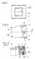
- FIG. 1 an embodiment of a display device according to the invention is shown in front view.
- a connecting element (V) is used here to firmly connect the liquid crystal cell (LCD) to a printed circuit board (L) and a reflector (R) that cannot be seen from this perspective and to make reliable contact.
- the liquid crystal cell (LCD) is designed here, for example, as a transmissive liquid crystal cell which has a rear lighting device.
- the liquid crystal cell (LCD) is constructed in a known manner from a glass cell which is filled with a nematic liquid, the transparent electrodes has, which are controlled by control electronics, not shown here, and which generally has polarization filters arranged in front of and behind the liquid crystal cell (LCD), which are often arranged in a crossed version in transmissive liquid crystal cells (LCD).
- the liquid crystal cell (LCD) used can also be a transflective liquid crystal cell (LCD) which then has a transflector which is not shown here and which is arranged behind the liquid crystal cell (LCD) from the direction of observation.
- FIG. 2 shows a side view of the display device according to the invention.
- the reflector (R) which is made here in one piece from plastic in order to ensure that it is inexpensive and easy to manufacture, is designed as a box-shaped component, for example.
- a connecting element (V) ensures that the liquid crystal cell (LCD) is on the one hand securely contacted with the printed circuit board (L) and on the other hand is firmly and immovably connected to the reflector (R).
- spacers (A) are used here as an example.
- the liquid crystal cell (LCD) together with the connecting element (V) and the printed circuit board (L) is at an angle (D) in this exemplary embodiment the central axis (MI) of the reflector (R).
- Figure 3 shows the detail Z marked in Figure 2 in a detailed sectional view.
- the reflector (R) lies with its edge facing the liquid crystal cell (LCD) firmly against the printed circuit board (L).
- Spacers (A) ensure that a minimum distance of the connecting element (V) to the circuit board (L) is maintained, whereby a secure fit of the liquid crystal cell (LCD) to the circuit board (L) and the reflector (R) is maintained.
- Holding elements (H) increase a diffusing screen (ST), which is designed here as a scattering film, and the uniformity of the illumination of the liquid crystal cell (LCD) and a filter (I), which is designed here as a color filter, which serves for color correction and prevents undesired color effects from occurring on the contours of the characters and symbols shown, held in a predetermined position with respect to the liquid crystal cell (LCD).
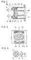
- FIG. 4 shows a top view of the reflector (R) of the display device according to the invention as a section.
- the reflector (R) is formed here in one piece at low cost.
- the reflector (R) has, for example, two facet reflectors (F1, F2) on its side facing the liquid crystal cell (LCD), each facet reflector (F1, F2) each having an opening (O) for receiving a light source.
- the light sources not shown in this illustration, the z. B. incandescent lamps or light emitting diodes have a different color radiation. This color radiation can be achieved in that the light source itself is colored or that the light source is surrounded by a hood-shaped or dome-shaped color filter.
- Each facet reflector (F1, F2) has a predetermined number of facets (C) which are arranged such that each facet (C) illuminates the liquid crystal cell (LCD), which is not shown here, uniformly.
- the facet reflectors (F1, F2) are arranged such that the Axis of symmetry (S) of each facet reflector (F1, F2) is directed to the center (M) of the liquid crystal cell (LCD), which is indicated in FIG. 1.
- each facet reflector (F1, F2) is angled to the central axis (MI) by a tilt angle (G) predetermined by the dimensions of the liquid crystal cell (LCD) and the reflector (R), which means that it is independent Uniform illumination of the liquid crystal cell (LCD) is achieved from the light source just switched on.
- Standard sockets for light bulbs or light-emitting diodes can be inserted into the openings (O) of the facet reflectors (F1, F2).
- the reflector (R) has locking elements (RE).
- the reflector (R) can also have a larger number of facet reflectors (F1, F2).
- individual light sources can be switched on individually or different light sources can be switched on in combination. The activation of the light sources is carried out by control electronics, not shown here.
- FIG. 5 shows a front view of the reflector (R) of the exemplary embodiment.
- the side of the reflector (R) opposite the liquid crystal cell (LCD) has two facet reflectors (F1, F2), in each of whose openings (O) a light source, which is not shown here, is attached via a holder can be.
- the outer edge of each facet reflector (F1, F2) facing the liquid crystal cell (LCD) is arranged in the plane of a partial area (T1, T2). These partial areas (T1, T2) are also identified in FIG. 4.
- Each sub-area (T1, T2) in order to achieve a simple construction and manufacturability and a high luminous efficiency, arranged such that the axis of symmetry (S) of each facet reflector (F1, F2) is directed to the center (M) of the liquid crystal cell (LCD), which is shown in FIG. 1 is designated.
- the facet reflectors (F1, F2) and the partial surfaces (T1, T2) are coated with a highly reflective coating.
- the inner side surfaces (W) of the reflector (R) are also coated with a reflective coating.
- the material used for the reflector (R) may have sufficient reflective properties in itself.
- the light directed through the partial areas (T1, T2) and the walls (W) onto the liquid crystal cell (LCD) largely consists of indirect radiation, which is reflected several times and thus leads to diffuse illumination of the liquid crystal cell (LCD). Since such a backlighting of the liquid crystal cell (LCD) would not be sufficient to display numbers and symbols with a sufficient contrast when light of strong light intensity comes from the observation direction, in particular if the display device is used to display safety-relevant parameters in motor vehicles , which are crucial for the safety of the operation of the motor vehicle, the facets (C) of the facet reflectors (F1, F2) are designed such that each facet directs the light impinging on it from the light source onto the liquid crystal cell (LCD) that the entire liquid crystal cell (LCD) is illuminated, whereby it is achieved that when switching on any light source, the liquid crystal cell (LCD) is illuminated with the same intensity and uniformity, but depending on the light source switched on, with different colors, whereby also when using light sources with low nominal power a Sufficient
- the reflector (R) can have more than two partial areas (T1, T2, ...) on its side facing the liquid crystal cell (LCD), the further partial areas (T1, T2, ...) each having a facet reflector (F1, F2, 7), each with a light source with different color radiation.
- FIG. 6 shows an embodiment of a facet reflector (F1, F2, ...) in two representations.
- the facet reflector (F1, F2, ...) has, for example, eight facets (C) and an opening (O) for receiving the light source, as can also be seen in FIGS. 4 and 5.
- the dimensioning of the facet reflectors (F1, F2, ...) is determined by the size of the partial areas (T1, T2, ...), the distance of the light sources from the liquid crystal cell (LCD) and by the size of the liquid crystal cell (LCD) .
- Given a predetermined size of the opening (O), the size of the surface to be illuminated can be determined at a predetermined distance by varying the angle (E).
- the angle (E) is approximately 45 °, for example.
- the embodiment and variation of this embodiment shown here open up the possibility of providing a reflector (R) which has the smallest possible depth and is therefore particularly space-saving, so that it can be used e.g. . B. can be easily installed in a display panel of a motor vehicle.
- the angle (E) indicates the angle of the facet surface to the axis of symmetry (S).
Abstract
Description
Die Erfindung betrifft eine Anzeigeeinrichtung, insbesondere in Kraftfahrzeugen, mit einer transmissiven oder transflektiven Flüssigkristallzelle, mit einer rückwärtigen Beleuchtungseinrichtung für die Flüssigkristallzelle, die mindestens zwei Lichtquellen mit unterschiedlicher Farbabstrahlung und einen Reflektor aufweist, mit einer Streuscheibe und mit einem Filter.The invention relates to a display device, in particular in motor vehicles, with a transmissive or transflective liquid crystal cell, with a rear lighting device for the liquid crystal cell, which has at least two light sources with different color radiation and a reflector, with a lens and with a filter.
Aus der deutschen Offenlegungsschrift DE-OS 36 27 697 ist eine Anzeigeeinrichtung mit einer Flüssigkristallzelle bekannt, die als eine transmissive Flüssigkristallzelle ausgebildet ist, die eine rückwärtige Beleuchtung aufweist, durch die Teile der Flüssigkristallzelle mit unterschiedlicher Farbgebung beleuchtet werden. Zu diesem Zweck weist die Anzeigeeinrichtung einen Reflektor und mindestens zwei Lichtquellen mit unterschiedlicher Farbabstrahlung auf, die getrennt voneinander einschaltbar sind. Zur Streuung des Lichts ist eine Streuscheibe, die hier als eine Streufolie ausgebildet ist, direkt hinter der Flüssigkristallzelle angeordnet. Zudem ist in dem Strahlengang ein Filter angeordnet, der hier als eine fluoreszierende Scheibe ausgebildet ist, die dazu dient, eine gleichmäßige Grundhelligkeit zu erzeugen und Farbverfälschungen zu vermeiden.From the German published patent application DE-OS 36 27 697 a display device with a liquid crystal cell is known, which is designed as a transmissive liquid crystal cell, which has a rear lighting, through which parts of the liquid crystal cell are illuminated with different colors. For this purpose, the display device has a reflector and at least two light sources with different color radiation, which can be switched on separately. To scatter the light, a diffusing screen, which is designed here as a scattering film, is arranged directly behind the liquid crystal cell. In addition, a filter is arranged in the beam path, which is designed here as a fluorescent disk, which serves to generate a uniform basic brightness and to avoid color distortions.
Als nachteilig erweist sich hierbei, daß durch die Ausbildung des Reflektors als Mehrkammerreflektor, das von den Lichtquellen ausgestrahlte Licht zu einem großen Teil nur über Mehrfachreflektion und damit indirekt auf die Flüssigkristallzelle gelangt, wodurch die erreichbare Lichtstärke sehr gering ist und damit der Kontrast der Anzeige nur gering ist und somit Fehler bei dem Ablesen auftreten können. Dieser Nachteil ergibt sich insbesondere dann, wenn bei einer transmissiven Flüssigkristallzelle Licht hoher Lichtintensität aus der Beobachtungsrichtung der Flüssigkristallzelle einfällt, so daß die Sicherheit z. B. bei dem Betrieb eines Kraftfahrzeugs, bei der die Anzeigeeinrichtung zur Übermittlung sicherheitsrelevanter Parameter dient, herabgesetzt wird und gefährliche Situationen heraufgerufen werden können. Weiterhin erweist sich als nachteilig, daß durch die Anordnung der farbiges Licht abstrahlenden Lichtquellen, je nachdem welche Lichtquelle eingeschaltet ist, eine unterschiedliche Ausleuchtung mit unterschiedlichen Lichtstärken und mit einer unterschiedlichen Gleichmäßigkeit erreicht wird. Weiterhin erweist sich als nachteilig, daß für eine gleichmäßige Ausleuchtung der Flüssigkristallzelle mit einer ausreichend hohen Lichtstärke, Lichtquellen mit hohen Nennleistungen erforderlich sind, die zu einer starken Aufheizung der Anzeigeeinrichtung und insbesondere bei der Verwendung in Kraftfahrzeugen zu einem hohen Leistungsverbrauch führen, der die Vorteile der Verwendung einer Flüssigkristallzelle als Anzeigeeinrichtung aufhebt.It turns out to be disadvantageous here that by designing the reflector as a multi-chamber reflector, the light emitted by the light sources to a large extent only reaches the liquid crystal cell via multiple reflection and thus indirectly, so that the achievable light intensity is very low and thus the contrast of the display only is low and errors can occur during reading. This disadvantage arises particularly when a transmissive liquid crystal cell Incident light of high light intensity from the direction of observation of the liquid crystal cell, so that the security z. B. in the operation of a motor vehicle, in which the display device is used to transmit safety-related parameters, is reduced and dangerous situations can be called. A further disadvantage is that the arrangement of the colored light-emitting light sources, depending on which light source is switched on, results in different illumination with different light intensities and with different uniformity. Furthermore, it proves to be disadvantageous that for uniform illumination of the liquid crystal cell with a sufficiently high light intensity, light sources with high nominal powers are required, which lead to a strong heating of the display device and, in particular when used in motor vehicles, to a high power consumption, which has the advantages of Abolishes use of a liquid crystal cell as a display device.
Aus dem deutschen Gebrauchsmuster G 86 34 222 ist eine Anzeigeeinrichtung mit einer Flüssigkristallzelle bekannt, die als eine transflektive Flüssigkristallzelle ausgebildet ist. Die Anzeigeeinrichtung verfügt über eine Beleuchtungseinrichtung zur rückwärtigen Beleuchtung der Flüssigkristallzelle, die einen Reflektor und Lichtquellen unterschiedlicher Farbabstrahlung aufweist, die getrennt voneinander einschaltbar sind. Zur Streuung des Lichts ist direkt hinter der Flüssigkristallzelle eine Streuscheibe angeordnet, die als eine Streufolie ausgebildet ist. In dem Strahlengang zwischen dem Reflektor und/oder den Lichtquellen und der Flüssigkristallzelle ist zudem ein Filter angeordnet, der als ein Farbfilter ausgebildet ist, durch den eine vorgegebene Farbtönung der Flüssigkristallzelle erreicht wird. Zudem ist bei dieser Ausführung in dem Strahlengang ein Transflektor angeordnet, der sowohl für das von den Lichtquellen oder dem Reflektor kommende Licht als auch für Licht, das aus der Beobachtungsrichtung auf den Transflektor auftrifft, teilreflektiv ist. Hierbei erweist sich als nachteilig, daß nur ein geringer Anteil des Lichts, das von den Lichtquellen ausgestrahlt wird, zur Ausleuchtung der Flüssigkristallzelle genutzt werden kann, da nur mehrfach reflektiertes Licht zu der Flüssigkristallzelle gelangt, wodurch die Lichtstärke nur durch die Verwendung von Lichtquellen hoher Nennleistung zur kontrastreichen Ausleuchtung der Flüssigkristallzelle ausreicht, was zu einer starken Erwärmung der Anzeigeeinrichtung und zu einem hohen Energieverbrauch führt. Bei der Verwendung von Lichtquellen, mit üblicher Nennleistung ergibt sich, insbesondere bei der Verwendung der Anzeigeeinrichtung zur Anzeige sicherheitsrelevanter Parameter in Kraftfahrzeugen, der Nachteil, daß gerade bei dem häufig auftretenden Fall, daß das von außen einfallende Licht nur eine mittlere Lichtstärke aufweist, die durch die Beleuchtungseinrichtung erreichbare Lichtstärke nicht ausreicht, um eine kontrastreiche Anzeige von Symbolen oder Buchstaben sicherzustellen, wodurch es zu gefährlichen Situationen bei dem Betrieb eines Kraftfahrzeugs kommen kann. Durch die nebeneinanderliegende Anordnung der Lichtquellen ergibt sich hier insbesondere der Nachteil, daß je nach eingeschalteter Lichtquelle die Flüssigkristallzelle in den Bereichen, die der eingeschalteten Lichtquelle näher liegen, stärker ausgeleuchtet wird als in Bereichen, die von der Lichtquelle weiter entfernt sind, wodurch je nach eingeschalteter Lichtquelle ein ungünstiger, verschieden gleichmäßiger Ausleuchtungseffekt der Flüssigkristallzelle erreicht wird.From the German utility model G 86 34 222 a display device with a liquid crystal cell is known, which is designed as a transflective liquid crystal cell. The display device has an illumination device for backlighting the liquid crystal cell, which has a reflector and light sources of different color radiation, which can be switched on separately. To scatter the light, a diffusing screen is arranged directly behind the liquid crystal cell, which is designed as a diffusing film. In the beam path between the reflector and / or the light sources and the liquid crystal cell, a filter is also arranged, which is designed as a color filter, through which a predetermined color tone of the liquid crystal cell is achieved. In addition, in this embodiment, a transflector is arranged in the beam path, which is used both for the light coming from the light sources or the reflector and for light coming from the Direction of observation strikes the transflector, is partially reflective. Here it turns out to be disadvantageous that only a small proportion of the light emitted by the light sources can be used to illuminate the liquid crystal cell, since only multiply reflected light reaches the liquid crystal cell, so that the light intensity is achieved only by using light sources of high nominal power sufficient for the high-contrast illumination of the liquid crystal cell, which leads to a strong heating of the display device and to a high energy consumption. When using light sources with the usual nominal power, especially when using the display device for displaying safety-related parameters in motor vehicles, there is the disadvantage that, especially in the frequently occurring case that the light coming in from the outside has only an average light intensity, which by the lighting device achievable light intensity is not sufficient to ensure a high-contrast display of symbols or letters, which can lead to dangerous situations when operating a motor vehicle. The side-by-side arrangement of the light sources results in particular in the disadvantage that, depending on the light source that is switched on, the liquid crystal cell is more strongly illuminated in the areas that are closer to the light source that is switched on than in areas that are further away from the light source, so that depending on the light source that is switched on Light source an unfavorable, differently uniform illumination effect of the liquid crystal cell is achieved.
Aus der britischen Patentanmeldung GB 20 61 587 ist eine Anzeigeeinrichtung bekannt, die eine transmissive Flüssigkristallzelle mit einer rückwärtigen Beleuchtungseinrichtung aufweist, die aus reflektierenden Mitteln und Lichtquellen mit unterschiedlicher Farbabstrahlung besteht. Der in üblicher Weise mit Polarisationsfiltern versehenen Flüssigkristallzelle ist eine Streuscheibe zugeordnet, die eine gleichmäßige Ausleuchtung der Flüssigkristallzelle bewirkt. Die Lichtquellen mit unterschiedlicher Farbabstrahlung sind getrennt einschaltbar. Um eine geringe Bautiefe der Beleuchtungseinrichtung zu gewährleisten, bestehen die reflektierenden Mittel aus ebenen Spiegeln, die in einem vorgegebenen Winkel zu der normalen Beobachtungsrichtung angeordnet sind, der kleiner 45° ist. Das von den Lichtquellen ausgestrahlte Licht wird dabei von den Spiegeln auf die Streuscheibe der Flüssigkristallzelle gelenkt.From the British patent application GB 20 61 587 a display device is known which has a transmissive liquid crystal cell with a rear lighting device which consists of reflecting means and light sources with different color radiation. The liquid crystal cell, which is provided with polarization filters in the usual way, is assigned a diffusing screen, which has a uniform Illumination of the liquid crystal cell causes. The light sources with different color radiation can be switched on separately. In order to ensure a small overall depth of the lighting device, the reflecting means consist of flat mirrors which are arranged at a predetermined angle to the normal direction of observation, which is less than 45 °. The light emitted by the light sources is directed by the mirrors onto the lens of the liquid crystal cell.
Als nachteilig erweist sich auch bei dieser Ausführung, daß je nach eingeschalteter Lichtquelle die Flüssigkristallzelle, in denen der Lichtquelle näher liegenden Bereichen stärker ausgeleuchtet wird, als in den Bereichen, die von der Lichtquelle weiter entfernt sind. Zudem erweist sich als nachteilig, daß ein großer Teil des von den Lichtquellen ausgestrahlten Lichts nicht zur Ausleuchtung der Flüssigkristallzelle verwendet werden kann, da ein umfassender Reflektor nicht vorgesehen ist. Damit ergibt sich insgesamt der Nachteil, daß bei dem Auftreffen von Licht aus der Beobachtungsrichtung, das eine hohe Lichtstärke aufweist, eine kontrastreiche Anzeige von Zeichen und Symbolen durch die Flüssigkristallzelle nicht gewährleistet ist, was insbesondere bei der Verwendung in Kraftfahrzeugen für die Anzeige von sicherheitsrelevanten Parametern zu gefährlichen Situationen führen kann.It also proves disadvantageous in this embodiment that, depending on the light source switched on, the liquid crystal cell in which areas closer to the light source are more strongly illuminated than in the areas which are further away from the light source. It also proves to be disadvantageous that a large part of the light emitted by the light sources cannot be used to illuminate the liquid crystal cell, since a comprehensive reflector is not provided. Overall, this results in the disadvantage that when light comes from the direction of observation, which has a high light intensity, a high-contrast display of signs and symbols is not guaranteed by the liquid crystal cell, which is particularly the case in motor vehicles for the display of safety-relevant parameters can lead to dangerous situations.
Aus dem deutschen Gebrauchsmuster G 85 10 864 ist eine Anzeigeeinrichtung bekannt, die eine transflektive Flüssigkristallzelle aufweist. Die Beleuchtungseinrichtung für die Flüssigkristallzelle besteht hierbei aus einer Lichtleiteranordnung, wobei die Lichtleiter mit einer Reflektorfolie hinterlegt sind. Zur Einkopplung von Licht unterschiedlicher Farbe sind zwei Einkopplungsstellen vorgesehen. Um eine Streuung des Lichts zu erreichen, ist zudem zwischen der Flüssigkristallzelle und dem Lichtleiter eine Streuscheibe, die hier als eine Streufolie ausgebildet ist, angeordnet.From the German utility model G 85 10 864 a display device is known which has a transflective liquid crystal cell. The lighting device for the liquid crystal cell here consists of a light guide arrangement, the light guides being backed with a reflector film. Two coupling points are provided for coupling light of different colors. In order to achieve a scattering of the light, a diffusing screen, which is designed here as a scattering film, is also arranged between the liquid crystal cell and the light guide.
Da die Einkopplung des farbigen Lichts an zwei Seiten der Flüssigkristallzelle erfolgt, ergibt sich hierbei der Nachteil, daß die erreichbare Lichtstärke zur Beleuchtung der Flüssigkristallzelle sich je nach eingeschalteter Lichtquelle über den gesamten Bereich der Flüssigkristallzelle unterscheidet, wodurch sich Ungleichmäßigkeiten in der Ausleuchtung und auch in der Farbgebung ergeben.Since the colored light is coupled in on two sides of the liquid crystal cell, there is the disadvantage that the achievable light intensity for illuminating the liquid crystal cell differs over the entire area of the liquid crystal cell, depending on the light source switched on, as a result of which irregularities in the illumination and also in the Coloring result.
Der Erfindung liegt die Aufgabe zugrunde, eine Anzeigeeinrichtung zu schaffen, bei der eine transmissive oder transflektive Flüssigkristallzelle durch Licht unterschiedlicher Farbe, unabhängig von der eingeschalteten Lichtquelle, bei einer möglichst platzsparenden, einfachen und kostengünstigen Herstellbarkeit und Ausführung der Anzeigeeinrichtung möglichst gleichmäßig, mit einer hohen Lichtstärke bei einer hohen Farbreinheit und einem möglichst guten Kontrast rückwärtig beleuchtet wird.The invention has for its object to provide a display device in which a transmissive or transflective liquid crystal cell by light of different colors, regardless of the light source switched on, with the most space-saving, simple and inexpensive manufacturability and design of the display device as uniformly as possible, with a high light intensity backlit with a high level of color purity and the best possible contrast.
Diese Aufgabe wird erfindungsgemäß dadurch gelöst, daß jede Lichtquelle auf der der Flüssigkristallzelle zugewandten Seite des Reflektors in der Öffnung je eines Facettenreflektors angeordnet ist und daß die Facetten des Facettenreflektors derart angeordnet sind, daß jede Facette die gesamte Flüssigkristallzelle beleuchtet.This object is achieved in that each light source is arranged on the side of the reflector facing the liquid crystal cell in the opening of one facet reflector and that the facets of the facet reflector are arranged such that each facet illuminates the entire liquid crystal cell.
Es ist von Vorteil, daß jede der Lichtquelle auf der der Flüssigkristallzelle zugewandten Seite des Reflektors in der Öffnung je eines Facettenreflektors angeordnet ist, weil somit eine optimale Ausnutzung des von der Lichtquelle ausgestrahlten Lichts erreicht wird.It is advantageous that each of the light sources is arranged on the side of the reflector facing the liquid crystal cell in the opening of each facet reflector, because optimal utilization of the light emitted by the light source is thus achieved.
In diesem Zusammenhang ist es besonders vorteilhaft, daß die Facetten des Facettenreflektors derart angeordnet sind, daß jede Facette die gesamte Flüssigkristallzelle beleuchtet, wodurch zum einen erreicht wird, daß ein möglichst großer Anteil des von der Lichtquelle abgestrahlten Lichts direkt auf die Flüssigkristallzelle gelenkt wird, wodurch eine hohe Lichtstärke erreicht wird und zum anderen erreicht wird, daß die Flüssigkristallzelle unabhängig von der eingeschalteten Lichtquelle möglichst gleichmäßig und mit einer hohen Farbreinheit ausgeleuchtet wird, was gewährleistet, daß auch bei einem Auftreffen von Licht aus der Beobachtungsrichtung mit einer hohen Lichtstärke eine kontrastreiche, fehlerfrei erkennbare, farbliche Darstellung von Symbolen und Zeichen gewährleistet ist, was insbesondere bei der Verwendung der Anzeigeeinrichtung zur Anzeige sicherheitsrelevanter Parameter, die Sicherheit bei dem Betrieb von Kraftfahrzeugen erhöht. Durch die Ausbildung der Facettenreflektoren wird dabei insbesondere eine einfache und kostengünstige und zugleich platzsparende Anzeigeeinrichtung geschaffen, so daß der Reflektor keine große Tiefe aufweisen muß, um zu gewährleisten, daß die Flüssigkristallzelle gleichmäßig und mit einer hohen Lichtstärke ausgeleuchtet wird.In this context, it is particularly advantageous that the facets of the facet reflector are arranged in such a way that each facet illuminates the entire liquid crystal cell, whereby on the one hand it is achieved that the largest possible proportion of the light emitted by the light source is directed directly onto the liquid crystal cell, whereby a high Luminous intensity is achieved and on the other hand it is achieved that the liquid crystal cell is illuminated as uniformly as possible and with a high degree of color purity, regardless of the switched-on light source, which ensures that even when light strikes from the direction of observation with a high luminous intensity a high-contrast, error-free, Color representation of symbols and characters is guaranteed, which increases the safety when operating motor vehicles, in particular when using the display device for displaying safety-relevant parameters. The design of the faceted reflectors in particular creates a simple and inexpensive and at the same time space-saving display device, so that the reflector does not have to have a great depth in order to ensure that the liquid crystal cell is illuminated uniformly and with a high light intensity.
Weitere vorteilhafte Ausgestaltungen und Weiterbildungen des Erfindungsgegenstands ergeben sich aus den Unteransprüchen.Further advantageous refinements and developments of the subject matter of the invention result from the subclaims.
Es ist vorteilhaft, daß die Symmetrieachse jedes Facettenreflektors auf den Mittelpunkt der Flüssigkristallzelle gerichtet ist, weil somit eine einfache und kostengünstige Ausführung und Herstellbarkeit der Facettenreflektoren gewährleistet ist.It is advantageous that the axis of symmetry of each facet reflector is directed to the center of the liquid crystal cell, because it ensures simple and inexpensive design and manufacturability of the facet reflectors.
Es ist vorteilhaft, daß jeder Facettenreflektor mit seinem der Flüssigkristallzelle zugewandten äußeren Rand in der Ebene je einer Teilfläche des Reflektors angeordnet ist und daß jede Teilfläche derart angeordnet ist, daß die Symmetrieachse jedes Facettenreflektors auf den Mittelpunkt der Flüssigkristallzelle gerichtet ist, weil somit zum einen eine einfache und kostengünstige Herstellbarkeit des Reflektors gewährleistet ist und nur ein geringer konstruktiver Aufwand erforderlich ist und zum anderen erreicht wird, daß die Anteile des von den Lichtquellen abgestrahlten Lichts, die nicht durch die Facettenreflektoren auf die Flüssigkristallzelle gelenkt werden, durch die Teilflächen auf die Flüssigkristallzelle gelenkt werden, wodurch die Ausnutzung des von den Lichtquellen ausgestrahlten Lichts weiter erhöht wird und zudem auch indirekte Strahlung der Flüssigkristallzelle zugeführt wird, wodurch die Gleichmäßigkeit der Ausleuchtung weiter erhöht wird.It is advantageous that each facet reflector with its outer edge facing the liquid crystal cell is arranged in the plane of a partial surface of the reflector and that each partial surface is arranged such that the axis of symmetry of each facet reflector is directed to the center of the liquid crystal cell, because on the one hand simple and inexpensive manufacturability of the reflector is ensured and only a small design effort is required and on the other hand it is achieved that the portions of the light emitted by the light sources that are not caused by the Facet reflectors are directed onto the liquid crystal cell, through which partial areas are directed onto the liquid crystal cell, as a result of which the utilization of the light emitted by the light sources is further increased and, moreover, indirect radiation is also supplied to the liquid crystal cell, which further increases the uniformity of the illumination.
Dadurch, daß die Facetten und die Teilflächen eine hochreflektierende Beschichtung aufweisen, ergibt sich der Vorteil einer besonders guten Ausnutzung des zur Verfügung stehenden Lichts, wodurch die Nennleistung der Lichtquellen gering gehalten werden kann, was zum einen zu Energieeinsparungen und zum anderen zu nur einer geringen Erwärmung der Anzeigeeinrichtung führt.The fact that the facets and the partial surfaces have a highly reflective coating gives the advantage of particularly good utilization of the available light, as a result of which the nominal power of the light sources can be kept low, which on the one hand results in energy savings and on the other hand only minimal heating the display device leads.
In diesem Zusammenhang ist es besonders vorteilhaft, daß die Seitenwände des Reflektors reflektierend beschichtet sind, weil somit die Lichtausnutzung nochmals erhöht wird.In this context, it is particularly advantageous that the side walls of the reflector are coated with a reflective coating, because the light utilization is thus increased again.
Dadurch, daß jede Lichtquelle von je einem haubenförmigen oder kalottenförmigen Farbfilter umgeben ist, ergibt sich der Vorteil, daß das von den Lichtquellen ausgestrahlte Licht eine einheitliche, intensive Farbgebung aufweist.Because each light source is surrounded by a hood-shaped or dome-shaped color filter, there is the advantage that the light emitted by the light sources has a uniform, intensive color.
Es ist von Vorteil, daß die Flüssigkristallzelle über Kontaktelemente mit einer elektronische Bauelemente tragenden Leiterplatte verbunden ist, die über ein Verbindungselement und Abstandhalter fest mit dem Reflektor verbunden ist und daß zwischen der Leiterplatte und der Flüssigkristallzelle über Halteelemente die Streuscheibe und der Filter angeordnet sind, weil auf diese Weise eine einfache und kostengünstige Montierbarkeit und Ausführung der Anzeigeeinrichtung gewährleistet wird, für eventuelle Wartungsarbeiten eine leichte Zugänglichkeit sichergestellt wird und insbesondere erreicht wird, daß alle Bauteile der Anzeigeeinrichtung eine feste unverrückbare Lage zueinander einnehmen und insbesondere die Kontaktierung der Flüssigkristallzelle zu der Leiterplatte eine hohe Sicherheit aufweist.It is advantageous that the liquid crystal cell is connected via contact elements to an electronic component-carrying circuit board, which is firmly connected to the reflector via a connecting element and spacers, and that the lens and the filter are arranged between the circuit board and the liquid crystal cell via holding elements, because in this way a simple and inexpensive mountability and design of the display device is ensured, easy accessibility is ensured for any maintenance work and in particular it is achieved that all components of the display device occupy a fixed, immovable position relative to one another and in particular the contacting of the Liquid crystal cell to the circuit board has a high security.
Dadurch, daß die Flüssigkristallzelle mit einem Winkel zu der Mittelachse des Reflektors angeordnet ist, ergibt sich der Vorteil, daß aus der Beobachtungsrichtung gesehen, ein möglichst hoher Kontrast bei der Anzeige von Zeichen und Symbolen erreicht wird.Because the liquid crystal cell is arranged at an angle to the central axis of the reflector, there is the advantage that, when viewed from the direction of observation, the highest possible contrast is achieved when characters and symbols are displayed.
Es ist von Vorteil, daß die Flüssigkristallzelle eine Punktmatrix-Flüssigkristallzelle ist, weil somit beliebige Zeichen und Symbole mit unterschiedlicher Farbgebung und hoher Gleichmäßigkeit der Lichtverteilung angezeigt werden können.It is advantageous that the liquid crystal cell is a dot matrix liquid crystal cell, because any characters and symbols with different colors and high uniformity of light distribution can thus be displayed.
Dadurch, daß der Reflektor einstückig aus Kunststoff gefertigt ist, ergibt sich der Vorteil einer besonders einfachen und kostengünstigen Herstellbarkeit der Anzeigeeinrichtung.The fact that the reflector is made in one piece from plastic gives the advantage of a particularly simple and inexpensive manufacture of the display device.
Es ist von Vorteil, daß jeder Facettenreflektor eine vorgegebene Anzahl Facetten aufweist und daß die Facetten zu der Symmetrieachse einen vorgegebenen Winkel aufweisen, wodurch eine möglichst gute Anpassung der von den Facetten beleuchteten Fläche an die Größe der Flüssigkristallzelle erreicht wird.It is advantageous that each facet reflector has a predetermined number of facets and that the facets have a predetermined angle with respect to the axis of symmetry, as a result of which the surface illuminated by the facets is matched as well as possible to the size of the liquid crystal cell.
Dadurch, daß die der Flüssigkristallzelle zugewandte Seite der Streuscheibe teilreflektiv ausgebildet ist, ergibt sich der Vorteil, daß insbesondere bei dem Auftreffen von Licht hoher Lichtstärke aus der Beobachtungsrichtung, der Kontrast bei der Anzeige von Zeichen und Symbolen erhöht wird, wodurch insbesondere bei der Verwendung der Anzeigeeinrichtung für die Anzeige sicherheitsrelevanter Parameter in Kraftfahrzeugen, die Sicherheit bei dem Betrieb des Kraftfahrzeugs erhöht wird.Characterized in that the side of the lens facing the liquid crystal cell is partially reflective, there is the advantage that, in particular when light of high light intensity comes from the direction of observation, the contrast in the display of characters and symbols is increased, which in particular when using the Display device for displaying safety-relevant parameters in motor vehicles, the safety during the operation of the motor vehicle is increased.
Ein Ausführungsbeispiel der Erfindung ist in den Zeichnungen dargestellt und wird im folgenden anhand der Zeichnungen näher beschrieben.An embodiment of the invention is shown in the drawings and is described in more detail below with reference to the drawings.
Es zeigen
- Figur 1 eine erfindungsgemäße Anzeigeeinrichtung in Vorderansicht,
- Figur 2 eine erfindungsgemäße Anzeigeeinrichtung in Seitenansicht,
- Figur 3 eine Einzelheit (Z) in vergrößertem Maßstab entsprechend Figur 2,
- Figur 4 eine Draufsicht auf den Reflektor der erfindungsgemäßen Anzeigeeinrichtung in Schnittdarstellung,
- Figur 5 eine Vorderansicht des Reflektors der erfindungsgemäßen Anzeigeeinrichtung,
- Figur 6 ein Ausführungsbeispiel eines Facettenreflektors.
- FIG. 1 shows a display device according to the invention in front view,
- FIG. 2 shows a display device according to the invention in side view,
- FIG. 3 shows a detail (Z) on an enlarged scale corresponding to FIG. 2,
- FIG. 4 shows a top view of the reflector of the display device according to the invention in a sectional view,
- FIG. 5 shows a front view of the reflector of the display device according to the invention,
- Figure 6 shows an embodiment of a facet reflector.
Gleiche oder gleichwirkende Bauteile und Merkmale sind in allen Figuren mit gleichen Bezugszeichen versehen.The same or equivalent components and features are provided with the same reference numerals in all figures.
In Figur 1 ist ein Ausführungsbeispiel einer erfindungsgemäßen Anzeigeeinrichtung in Vorderansicht dargestellt. Ein Verbindungselement (V) dient hier dazu, die Flüssigkristallzelle (LCD) mit einer Leiterplatte (L) und einem aus dieser Perspektive nicht erkennbaren Reflektor (R) fest zu verbinden und sicher zu kontaktieren. Die Flüssigkristallzelle (LCD) ist hier beispielhaft als eine transmissive Flüssigkristallzelle ausgebildet, die eine rückwärtige Beleuchtungseinrichtung aufweist. Die Flüssigkristallzelle (LCD) ist dabei in bekannter Weise aus einer Glaszelle aufgebaut, die mit einer nematischen Flüssigkeit gefüllt ist, die durchsichtige Elektroden aufweist, die von einer hier nicht gezeigten Ansteuerelektronik angesteuert werden und die in der Regel über vor und hinter der Flüssigkristallzelle (LCD) angeordnete Polarisationsfilter verfügt, die bei transmissiven Flüssigkristallzellen (LCD) häufig in gekreuzter Ausführung angeordnet sind. Bei einem anderen Ausführungsbeispiel kann die verwendete Flüssigkristallzelle (LCD) auch eine transflektive Flüssigkristallzelle (LCD) sein, die dann über einen Transflektor verfügt, der hier nicht gezeigt ist und der aus der Beobachtungsrichtung hinter der Flüssigkristallzelle (LCD) angeordnet ist.In Figure 1, an embodiment of a display device according to the invention is shown in front view. A connecting element (V) is used here to firmly connect the liquid crystal cell (LCD) to a printed circuit board (L) and a reflector (R) that cannot be seen from this perspective and to make reliable contact. The liquid crystal cell (LCD) is designed here, for example, as a transmissive liquid crystal cell which has a rear lighting device. The liquid crystal cell (LCD) is constructed in a known manner from a glass cell which is filled with a nematic liquid, the transparent electrodes has, which are controlled by control electronics, not shown here, and which generally has polarization filters arranged in front of and behind the liquid crystal cell (LCD), which are often arranged in a crossed version in transmissive liquid crystal cells (LCD). In another exemplary embodiment, the liquid crystal cell (LCD) used can also be a transflective liquid crystal cell (LCD) which then has a transflector which is not shown here and which is arranged behind the liquid crystal cell (LCD) from the direction of observation.
In Figur 2 ist eine Seitenansicht der erfindungsgemäßen Anzeigeeinrichtung dargestellt. Der Reflektor (R), der hier, um eine kostengünstige und einfache Herstellbarkeit zu gewährleisten, einstückig aus Kunststoff gefertigt ist, ist beispielhaft als ein kastenförmiges Bauteil ausgeführt. Wie schon unter Figur 1 beschrieben, stellt ein Verbindungselement (V) sicher, daß die Flüssigkristallzelle (LCD) zum einen sicher mit der Leiterplatte (L) kontaktiert wird und zum anderen fest und unverrückbar mit dem Reflektor (R) verbunden ist. Zur Einhaltung eines vorgegebenen Abstands werden dabei hier beispielhaft Abstandshalter (A) eingesetzt. Um einen möglichst hohen Kontrast bei der Anzeige von Zeichen und Symbolen durch die Flüssigkristallzelle (LCD) zu erreichen, ist die Flüssigkristallzelle (LCD) bei diesem Ausführungsbeispiel zusammen mit dem Verbindungselement (V) und der Leiterplatte (L) mit einem Winkel (D) zu der Mittelachse (MI) des Reflektors (R) angeordnet.FIG. 2 shows a side view of the display device according to the invention. The reflector (R), which is made here in one piece from plastic in order to ensure that it is inexpensive and easy to manufacture, is designed as a box-shaped component, for example. As already described under Figure 1, a connecting element (V) ensures that the liquid crystal cell (LCD) is on the one hand securely contacted with the printed circuit board (L) and on the other hand is firmly and immovably connected to the reflector (R). To maintain a predetermined distance, spacers (A) are used here as an example. In order to achieve the highest possible contrast in the display of characters and symbols by the liquid crystal cell (LCD), the liquid crystal cell (LCD) together with the connecting element (V) and the printed circuit board (L) is at an angle (D) in this exemplary embodiment the central axis (MI) of the reflector (R).
Figur 3 zeigt die in Figur 2 gekennzeichnete Einzelheit Z in einer detaillierten Schnittdarstellung. Der Reflektor (R) liegt dabei mit seinem der Flüssigkristallzelle (LCD) zugewandten Rand fest an der Leiterplatte (L) an. Das Verbindungselement (V), das ebenso wie die Leiterplatte (L) einen Ausschnitt für die Flüssigkristallzelle (LCD) aufweist, liegt dabei fest auf der FLüssigkristallzelle (LCD) auf und drückt diese gegen Kontaktelemente (K), die mit Leiterbahnen auf der Leiterplatte (L) verbunden sind.Figure 3 shows the detail Z marked in Figure 2 in a detailed sectional view. The reflector (R) lies with its edge facing the liquid crystal cell (LCD) firmly against the printed circuit board (L). The connecting element (V), which, like the printed circuit board (L), has a cutout for the liquid crystal cell (LCD), lies firmly on the liquid crystal cell (LCD) and presses them against contact elements (K) that are connected to conductor tracks on the circuit board (L).
Abstandhalter (A) sorgen dabei dafür, daß ein minimaler Abstand des Verbindungselements (V) zu der Leiterplatte (L) eingehalten wird, wodurch ein sicherer Sitz der Flüssigkristallzelle (LCD) zu der Leiterplatte (L) und dem Reflektor (R) eingehalten wird. Durch Halteelemente (H) wird eine Streuscheibe (ST), die hier als eine Streufolie ausgebildet ist, und die Gleichmäßigkeit der Ausleuchtung der Flüssigkristallzelle (LCD) erhöht und ein Filter (I), der hier als ein Farbfilter ausgebildet ist, der der Farbkorrektur dient und vermeidet, daß ungewünschte Farbeffekte an den Konturen der dargestellten Zeichen und Symbolen auftreten, in einer vorgegebenen Position zu der Flüssigkristallzelle (LCD) gehalten.Spacers (A) ensure that a minimum distance of the connecting element (V) to the circuit board (L) is maintained, whereby a secure fit of the liquid crystal cell (LCD) to the circuit board (L) and the reflector (R) is maintained. Holding elements (H) increase a diffusing screen (ST), which is designed here as a scattering film, and the uniformity of the illumination of the liquid crystal cell (LCD) and a filter (I), which is designed here as a color filter, which serves for color correction and prevents undesired color effects from occurring on the contours of the characters and symbols shown, held in a predetermined position with respect to the liquid crystal cell (LCD).
In Figur 4 ist eine Draufsicht des Reflektors (R) der erfindungsgemäßen Anzeigeeinrichtung als Schnitt dargestellt. Der Reflektor (R) ist hier kostengünstig einstückig ausgebildet. Der Reflektor (R) verfügt beispielhaft auf seiner der Flüssigkristallzelle (LCD) zugewandten Seite über zwei Facettenreflektoren (F1, F2), wobei jeder Facettenreflektor (F1, F2) je eine Öffnung (O) zur Aufnahme einer Lichtquelle aufweist. Die in dieser Darstellung nicht gezeigten Lichtquellen, die z. B. Glühlampen oder Leuchtdioden sein können, weisen eine unterschiedliche Farbabstrahlung auf. Diese Farbabstrahlung kann dadurch erreicht werden, daß die Lichtquelle selbst farblich gefärbt ist oder aber, daß die Lichtquelle von einem haubenförmigen oder kalottenförmigen Farbfilter umgeben ist. Jeder Facettenreflektor (F1, F2) weist eine vorgegebene Anzahl Facetten (C) auf, die derart angeordnet sind, daß jede Facette (C) die Flüssigkristallzelle (LCD), die hier nicht dargestellt ist, gleichmäßig beleuchtet. Um eine kostengünstige und einfache Konstruktion und Herstellbarkeit zu gewährleisten, sind die Facettenreflektoren (F1, F2) derart angeordnet, daß die Symmetrieachse (S) jedes Facettenreflektors (F1, F2) auf den Mittelpunkt (M) der Flüssigkristallzelle (LCD), der in Figur 1 angegeben ist, gerichtet ist. Bei dem hier gezeigten Ausführungsbeispiel wird dies dadurch erreicht, daß jeder Facettenreflektor (F1, F2) um einen durch die Abmessungen der Flüssigkristallzelle (LCD) und des Reflektors (R) vorgegebenen Kippwinkel (G) zu der Mittelachse (MI) angewinkelt ist, wodurch unabhängig von der gerade eingeschalteten Lichtquelle eine gleichmäßige Beleuchtung der Flüssigkristallzelle (LCD) erreicht wird.FIG. 4 shows a top view of the reflector (R) of the display device according to the invention as a section. The reflector (R) is formed here in one piece at low cost. The reflector (R) has, for example, two facet reflectors (F1, F2) on its side facing the liquid crystal cell (LCD), each facet reflector (F1, F2) each having an opening (O) for receiving a light source. The light sources not shown in this illustration, the z. B. incandescent lamps or light emitting diodes have a different color radiation. This color radiation can be achieved in that the light source itself is colored or that the light source is surrounded by a hood-shaped or dome-shaped color filter. Each facet reflector (F1, F2) has a predetermined number of facets (C) which are arranged such that each facet (C) illuminates the liquid crystal cell (LCD), which is not shown here, uniformly. To ensure an inexpensive and simple construction and manufacturability, the facet reflectors (F1, F2) are arranged such that the Axis of symmetry (S) of each facet reflector (F1, F2) is directed to the center (M) of the liquid crystal cell (LCD), which is indicated in FIG. 1. In the embodiment shown here, this is achieved in that each facet reflector (F1, F2) is angled to the central axis (MI) by a tilt angle (G) predetermined by the dimensions of the liquid crystal cell (LCD) and the reflector (R), which means that it is independent Uniform illumination of the liquid crystal cell (LCD) is achieved from the light source just switched on.
In die öffnungen (O) der Facettenreflektoren (F1, F2) können dabei übliche Fassungen für Glühbirnen oder Leuchtdioden eingesetzt werden. Um eine rückwärtige Befestigung des Reflektors (R) zu gewährleisten, verfügt der Reflektor (R) über Rastelemente (RE). Bei einem anderen Ausführungsbeispiel kann der Reflektor (R) auch über eine größere Anzahl Facettenreflektoren (F1, F2) verfügen. Zur Erzeugung unterschiedlicher Farbdarstellungen können dabei jeweils einzelne Lichtquellen einzeln eingeschaltet werden oder aber auch verschiedene Lichtquellen in Kombination eingeschaltet werden. Die Einschaltung der Lichtquellen, wird dabei von einer hier nicht gezeigten Ansteuerelektronik übernommen.Standard sockets for light bulbs or light-emitting diodes can be inserted into the openings (O) of the facet reflectors (F1, F2). To ensure that the reflector (R) is attached to the rear, the reflector (R) has locking elements (RE). In another embodiment, the reflector (R) can also have a larger number of facet reflectors (F1, F2). To generate different color representations, individual light sources can be switched on individually or different light sources can be switched on in combination. The activation of the light sources is carried out by control electronics, not shown here.
In Figur 5 ist eine Vorderansicht des Reflektors (R) des Ausführungsbeispiels dargestellt. Wie schon in Figur 4 dargestellt, weist die der Flüssigkristallzelle (LCD) gegenüberliegende Seite des Reflektors (R) zwei Facettenreflektoren (F1, F2) auf, in deren Öffnungen (O) jeweils eine Lichtquelle, die hier nicht gezeigt ist, über eine Fassung angebracht werden kann. Um eine einfache und kostengünstigere Herstellbarkeit und eine einfache Konstruktion zu ermöglichen, ist der der Flüssigkristallzelle (LCD) zugewandte äußere Rand jedes Facettenreflektors (F1, F2) in der Ebene je einer Teilfläche (T1, T2) angeordnet. Diese Teilflächen (T1, T2) sind auch in der Figur 4 gekennzeichnet. Dabei ist jede Teilfläche (T1, T2), um eine einfache Konstruktion und Herstellbarkeit und eine hohe Lichtausbeute zu erreichen, derart angeordnet, daß die Symmetrieachse (S) jedes Facettenreflektors (F1, F2) auf den Mittelpunkt (M) der Flüssigkristallzelle (LCD) gerichtet ist, der in Figur 1 bezeichnet ist. Die Facettenreflektoren (F1, F2) und die Teilflächen (T1, T2) sind dabei hochreflektierend beschichtet. Um eine weitere Steigerung der Lichtausbeute zu erreichen und eine gleichmäßigere Beleuchtung der Flüssigkristallzelle (LCD) zu gewährleisten sind auch die innenliegenden Seitenflächen (W) des Reflektors (R) reflektierend beschichtet. Bei einem abweichenden Ausführungsbeispiel kann das für den Reflektor (R) verwendete Material schon für sich ausreichende reflektierende Eigenschaften aufweisen.FIG. 5 shows a front view of the reflector (R) of the exemplary embodiment. As already shown in FIG. 4, the side of the reflector (R) opposite the liquid crystal cell (LCD) has two facet reflectors (F1, F2), in each of whose openings (O) a light source, which is not shown here, is attached via a holder can be. In order to enable simple and inexpensive manufacture and simple construction, the outer edge of each facet reflector (F1, F2) facing the liquid crystal cell (LCD) is arranged in the plane of a partial area (T1, T2). These partial areas (T1, T2) are also identified in FIG. 4. Each sub-area (T1, T2), in order to achieve a simple construction and manufacturability and a high luminous efficiency, arranged such that the axis of symmetry (S) of each facet reflector (F1, F2) is directed to the center (M) of the liquid crystal cell (LCD), which is shown in FIG. 1 is designated. The facet reflectors (F1, F2) and the partial surfaces (T1, T2) are coated with a highly reflective coating. In order to achieve a further increase in the luminous efficacy and to ensure more uniform illumination of the liquid crystal cell (LCD), the inner side surfaces (W) of the reflector (R) are also coated with a reflective coating. In a different embodiment, the material used for the reflector (R) may have sufficient reflective properties in itself.
Das durch die Teilflächen (T1, T2) und die Wände (W) auf die Flüssigkristallzelle (LCD) gelenkte Licht besteht zu einem großen Teil aus indirekter Strahlung, die mehrfach reflektiert ist und somit zu einer diffusen Ausleuchtung der Flüssigkristallzelle (LCD) führt. Da bei einem Auftreffen von Licht starker Lichtstärke aus der Beobachtungsrichtung eine solche rückwärtige Beleuchtung der Flüssigkristallzelle (LCD) nicht ausreichen würde, um Zahlen und Symbole mit einem ausreichenden Kontrast darzustellen, insbesondere dann, wenn die Anzeigeeinrichtung für die Anzeige von sicherheitsrelevanten Parametern in Kraftfahrzeugen verwendet wird, die für die Sicherheit bei dem Betrieb des Kraftfahrzeugs entscheidend sind, sind die Facetten (C) der Facettenreflektoren (F1, F2) derart ausgebildet, daß jede Facette für sich das auf sie von der Lichtquelle auftreffende Licht derart auf die Flüssigkristallzelle (LCD) lenkt, daß die gesamte Flüssigkristallzelle (LCD) beleuchtet wird, wodurch erreicht wird, daß bei dem Einschalten einer beliebigen Lichtquelle die Flüssigkristallzelle (LCD) mit gleicher Intensität und Gleichmäßigkeit jedoch in Abhängigkeit von der eingeschalteten Lichtquelle mit unterschiedlicher Farbe beleuchtet wird, wobei auch bei der Verwendung von Lichtquellen mit geringer Nennleistung eine genügend hohe Lichtstärke für eine optimale Ausleuchtung der Flüssigkristallzelle (LCD) erreicht wird.The light directed through the partial areas (T1, T2) and the walls (W) onto the liquid crystal cell (LCD) largely consists of indirect radiation, which is reflected several times and thus leads to diffuse illumination of the liquid crystal cell (LCD). Since such a backlighting of the liquid crystal cell (LCD) would not be sufficient to display numbers and symbols with a sufficient contrast when light of strong light intensity comes from the observation direction, in particular if the display device is used to display safety-relevant parameters in motor vehicles , which are crucial for the safety of the operation of the motor vehicle, the facets (C) of the facet reflectors (F1, F2) are designed such that each facet directs the light impinging on it from the light source onto the liquid crystal cell (LCD) that the entire liquid crystal cell (LCD) is illuminated, whereby it is achieved that when switching on any light source, the liquid crystal cell (LCD) is illuminated with the same intensity and uniformity, but depending on the light source switched on, with different colors, whereby also when using light sources with low nominal power a Sufficiently high light intensity for optimal illumination of the liquid crystal cell (LCD) is achieved.
Ist es erforderlich, daß die Flüssigkristallzelle (LCD) mit mehr als zwei Farben beleuchtet wird, so kann der Reflektor (R) an seiner der Flüssigkristallzelle (LCD) zugewandten Seite über mehr als zwei Teilflächen (T1, T2, ...) verfügen, wobei die weiteren Teilflächen (T1, T2, ...) jeweils einen Facettenreflektor (F1, F2, ...) mit je einer Lichtquelle unterschiedlicher Farbabstrahlung aufweisen.If it is necessary for the liquid crystal cell (LCD) to be illuminated with more than two colors, the reflector (R) can have more than two partial areas (T1, T2, ...) on its side facing the liquid crystal cell (LCD), the further partial areas (T1, T2, ...) each having a facet reflector (F1, F2, ...), each with a light source with different color radiation.
In Figur 6 ist ein Ausführungsbeispiel eines Facettenreflektors (F1, F2, ...) in zwei Darstellungen gezeigt. Der Facettenreflektor (F1, F2, ...) weist hier beispielhaft, wie auch schon aus den Figuren 4 und 5 entnehmbar, acht Facetten (C) und eine Öffnung (O) zur Aufnahme der Lichtquelle auf. Die Dimensionierung der Facettenreflektoren (F1, F2, ...) ist dabei durch die Größe der Teilflächen (T1, T2, ...), den Abstand der Lichtquellen zu der Flüssigkristallzelle (LCD) und durch die Größe der Flüssigkristallzelle (LCD) bestimmt. Bei einer vorgegebenen Größe der Öffnung (O) kann durch Variation des Winkels (E) die Größe der zu beleuchtenden Fläche in einem vorgegebenen Abstand bestimmt werden. Bei dem hier gezeigten Ausführungsbeispiel beträgt der Winkel (E) beispielhaft etwa 45°. Je nach dem für die Anzeigeeinrichtung zur Verfügung stehenden Platz wird durch die hier gezeigte Ausführungsform und Variation dieser Ausführungsform die Möglichkeit eröffnet, einen Reflektor (R) zur Verfügung zu stellen, der eine möglichst geringe Bautiefe aufweist und somit besonders platzsparend ist, so daß er z. B. bei einer Montage in einer Anzeigetafel eines Kraftfahrzeugs problemlos eingebaut werden kann. Der Winkel (E) gibt den Winkel der Facettenfläche zu der Symmetrieachse (S) an.FIG. 6 shows an embodiment of a facet reflector (F1, F2, ...) in two representations. The facet reflector (F1, F2, ...) has, for example, eight facets (C) and an opening (O) for receiving the light source, as can also be seen in FIGS. 4 and 5. The dimensioning of the facet reflectors (F1, F2, ...) is determined by the size of the partial areas (T1, T2, ...), the distance of the light sources from the liquid crystal cell (LCD) and by the size of the liquid crystal cell (LCD) . Given a predetermined size of the opening (O), the size of the surface to be illuminated can be determined at a predetermined distance by varying the angle (E). In the exemplary embodiment shown here, the angle (E) is approximately 45 °, for example. Depending on the space available for the display device, the embodiment and variation of this embodiment shown here open up the possibility of providing a reflector (R) which has the smallest possible depth and is therefore particularly space-saving, so that it can be used e.g. . B. can be easily installed in a display panel of a motor vehicle. The angle (E) indicates the angle of the facet surface to the axis of symmetry (S).
Claims (12)
Applications Claiming Priority (2)
| Application Number | Priority Date | Filing Date | Title |
|---|---|---|---|
| DE3921304 | 1989-06-29 | ||
| DE3921304A DE3921304A1 (en) | 1989-06-29 | 1989-06-29 | DISPLAY DEVICE |
Publications (3)
| Publication Number | Publication Date |
|---|---|
| EP0405286A2 true EP0405286A2 (en) | 1991-01-02 |
| EP0405286A3 EP0405286A3 (en) | 1991-07-24 |
| EP0405286B1 EP0405286B1 (en) | 1993-05-05 |
Family
ID=6383859
Family Applications (1)
| Application Number | Title | Priority Date | Filing Date |
|---|---|---|---|
| EP90111494A Expired - Lifetime EP0405286B1 (en) | 1989-06-29 | 1990-06-19 | Display device |
Country Status (3)
| Country | Link |
|---|---|
| EP (1) | EP0405286B1 (en) |
| DE (2) | DE3921304A1 (en) |
| ES (1) | ES2041079T3 (en) |
Cited By (4)
| Publication number | Priority date | Publication date | Assignee | Title |
|---|---|---|---|---|
| EP0850799A3 (en) * | 1996-12-24 | 1999-06-09 | Mannesmann VDO Aktiengesellschaft | Indication unit with transparent indicating element |
| FR2862140A1 (en) * | 2003-11-07 | 2005-05-13 | Thales Sa | LIGHT BOX WITH ELECTROMUMINESCENT DIODES FOR VISUALIZATIONS |
| WO2005073617A2 (en) * | 2004-01-22 | 2005-08-11 | Siemens Vdo Automotive Corporation | Illuminated display having two single-colored light sources |
| CN113715726A (en) * | 2020-10-27 | 2021-11-30 | 株式会社瑞延理化 | Intelligent ornament for automobile |
Families Citing this family (4)
| Publication number | Priority date | Publication date | Assignee | Title |
|---|---|---|---|---|
| DE19621919A1 (en) * | 1996-05-31 | 1997-12-04 | Hella Kg Hueck & Co | Display device for motor vehicles |
| DE19754192B4 (en) * | 1997-12-06 | 2004-07-29 | Valeo Schalter Und Sensoren Gmbh | Switching system with an evaluation device |
| DE102007018719A1 (en) * | 2007-04-20 | 2008-10-23 | Preh Gmbh | Display device in a motor vehicle |
| DE102007043379A1 (en) * | 2007-09-12 | 2009-04-09 | Behr-Hella Thermocontrol Gmbh | Display device for control panel of air-conditioning system of car, has separation wall between adjacent subareas of symbol areas including distance to LCD-display element for backlighting subareas by light of light sources |
Citations (4)
| Publication number | Priority date | Publication date | Assignee | Title |
|---|---|---|---|---|
| US3674341A (en) * | 1970-12-08 | 1972-07-04 | Scm Corp | Liquid crystal display device having improved optical contrast |
| GB2061587A (en) * | 1979-09-10 | 1981-05-13 | Stolov M | Electronically controlled colour displays |
| EP0239766A1 (en) * | 1986-02-28 | 1987-10-07 | Siemens Aktiengesellschaft | Display device provided with a contacting device for a display element, particularly for a liquid-crystal display |
| EP2397766A1 (en) * | 2010-03-01 | 2011-12-21 | Broseley Fires Limited | Solid fuel stove and liquid heating system |
Family Cites Families (4)
| Publication number | Priority date | Publication date | Assignee | Title |
|---|---|---|---|---|
| HU179357B (en) * | 1979-04-26 | 1982-10-28 | Villamos Berendezes Es Elektro | Method and apparatus for implemetning color light indicating |
| DE8510864U1 (en) * | 1985-04-13 | 1985-05-30 | Diemer & Fastenrath, 5880 Lüdenscheid | Transflective liquid crystal display |
| DE3627697A1 (en) * | 1986-08-14 | 1988-02-25 | Bosch Gmbh Robert | DISPLAY DEVICE WITH LIQUID CRYSTAL CELL, PREFERABLY FOR MOTOR VEHICLES |
| DE3643841A1 (en) * | 1986-12-20 | 1988-06-30 | Bosch Gmbh Robert | DISPLAY DEVICE WITH LIQUID CRYSTAL CELL |
-
1989
- 1989-06-29 DE DE3921304A patent/DE3921304A1/en active Granted
-
1990
- 1990-06-19 DE DE9090111494T patent/DE59001346D1/en not_active Expired - Fee Related
- 1990-06-19 EP EP90111494A patent/EP0405286B1/en not_active Expired - Lifetime
- 1990-06-19 ES ES199090111494T patent/ES2041079T3/en not_active Expired - Lifetime
Patent Citations (4)
| Publication number | Priority date | Publication date | Assignee | Title |
|---|---|---|---|---|
| US3674341A (en) * | 1970-12-08 | 1972-07-04 | Scm Corp | Liquid crystal display device having improved optical contrast |
| GB2061587A (en) * | 1979-09-10 | 1981-05-13 | Stolov M | Electronically controlled colour displays |
| EP0239766A1 (en) * | 1986-02-28 | 1987-10-07 | Siemens Aktiengesellschaft | Display device provided with a contacting device for a display element, particularly for a liquid-crystal display |
| EP2397766A1 (en) * | 2010-03-01 | 2011-12-21 | Broseley Fires Limited | Solid fuel stove and liquid heating system |
Cited By (8)
| Publication number | Priority date | Publication date | Assignee | Title |
|---|---|---|---|---|
| EP0850799A3 (en) * | 1996-12-24 | 1999-06-09 | Mannesmann VDO Aktiengesellschaft | Indication unit with transparent indicating element |
| FR2862140A1 (en) * | 2003-11-07 | 2005-05-13 | Thales Sa | LIGHT BOX WITH ELECTROMUMINESCENT DIODES FOR VISUALIZATIONS |
| WO2005045943A1 (en) * | 2003-11-07 | 2005-05-19 | Thales | Lightbox with leds for displays |
| WO2005073617A2 (en) * | 2004-01-22 | 2005-08-11 | Siemens Vdo Automotive Corporation | Illuminated display having two single-colored light sources |
| WO2005073617A3 (en) * | 2004-01-22 | 2006-02-09 | Siemens Vdo Automotive Corp | Illuminated display having two single-colored light sources |
| US7506996B2 (en) | 2004-01-22 | 2009-03-24 | Continental Automotive Systems Us, Inc. | Illuminated display having two single-colored light sources |
| CN113715726A (en) * | 2020-10-27 | 2021-11-30 | 株式会社瑞延理化 | Intelligent ornament for automobile |
| CN113715726B (en) * | 2020-10-27 | 2023-07-25 | 株式会社瑞延理化 | Intelligent ornament for automobile |
Also Published As
| Publication number | Publication date |
|---|---|
| EP0405286B1 (en) | 1993-05-05 |
| EP0405286A3 (en) | 1991-07-24 |
| DE3921304C2 (en) | 1991-06-20 |
| DE3921304A1 (en) | 1991-01-10 |
| DE59001346D1 (en) | 1993-06-09 |
| ES2041079T3 (en) | 1993-11-01 |
Similar Documents
| Publication | Publication Date | Title |
|---|---|---|
| EP1166013B1 (en) | Front-illuminated Display Device | |
| EP0333709B1 (en) | Liquid crystal indicator, preferably for motor vehicles | |
| DE10258465B4 (en) | Lighting device for a license plate | |
| EP1231430B1 (en) | Illumination device with point light sources | |
| EP0799430B1 (en) | Arrangement including a lighting fitting with a diffuser | |
| EP0780265A2 (en) | Vehicle rear light | |
| EP1523431B1 (en) | Lights for motor vehicles | |
| EP0405286B1 (en) | Display device | |
| EP1152186B1 (en) | Display illumination device | |
| EP0225977B1 (en) | Illuminating device | |
| EP1696260B1 (en) | Liquid crystal display and liquid crystal display system comprising a plurality of such liquid crystal displays | |
| WO2015154939A1 (en) | Device for displaying a symbol and method for producing a device for displaying a symbol | |
| DE112019001649B4 (en) | ELECTRICAL DEVICE FOR A VEHICLE FOOTBOARD | |
| DE4105547A1 (en) | Flat illuminated display esp. for symbols and lettering - has gap between translucent lettered cover and light conductive component cross=sectioned for diffuse reflection from rear face | |
| DE10338691A1 (en) | Background lighting for liquid crystal displays has a defined radiation flux with spectral color components at an operating point | |
| DE3032344A1 (en) | LIQUID CRYSTAL DISPLAYS | |
| EP0742470B1 (en) | Multicolour illumination apparatus | |
| DE102007060516B4 (en) | Reading light of a vehicle for illuminating a predetermined reading surface | |
| DE3302156A1 (en) | LIGHTING DEVICE FOR A TRANSMISSIVELY OPERABLE PASSIVE DISPLAY | |
| DE202005005306U1 (en) | Transreflective LCD device, has diffusing panel arranged behind LCD-unit, LED arranged in border area surrounding panel and unit, and light reflecting device having reflector concavely curved from LED to reflect light to panel/unit | |
| DE4119801C2 (en) | Display device for motor vehicles | |
| EP1136751A1 (en) | Warning and security lamp | |
| DE19746854A1 (en) | Escape indication light with light emitting diodes for emergency operation | |
| EP0045831B1 (en) | Passive display device | |
| DE3129038A1 (en) | Illuminated sign |
Legal Events
| Date | Code | Title | Description |
|---|---|---|---|
| PUAI | Public reference made under article 153(3) epc to a published international application that has entered the european phase |
Free format text: ORIGINAL CODE: 0009012 |
|
| AK | Designated contracting states |
Kind code of ref document: A2 Designated state(s): DE ES FR GB IT |
|
| PUAL | Search report despatched |
Free format text: ORIGINAL CODE: 0009013 |
|
| AK | Designated contracting states |
Kind code of ref document: A3 Designated state(s): DE ES FR GB IT |
|
| 17P | Request for examination filed |
Effective date: 19911216 |
|
| 17Q | First examination report despatched |
Effective date: 19921023 |
|
| ITF | It: translation for a ep patent filed |
Owner name: INTERPATENT ST.TECN. BREV. |
|
| GRAA | (expected) grant |
Free format text: ORIGINAL CODE: 0009210 |
|
| AK | Designated contracting states |
Kind code of ref document: B1 Designated state(s): DE ES FR GB IT |
|
| REF | Corresponds to: |
Ref document number: 59001346 Country of ref document: DE Date of ref document: 19930609 |
|
| GBT | Gb: translation of ep patent filed (gb section 77(6)(a)/1977) |
Effective date: 19930615 |
|
| ET | Fr: translation filed | ||
| REG | Reference to a national code |
Ref country code: ES Ref legal event code: FG2A Ref document number: 2041079 Country of ref document: ES Kind code of ref document: T3 |
|
| PLBE | No opposition filed within time limit |
Free format text: ORIGINAL CODE: 0009261 |
|
| STAA | Information on the status of an ep patent application or granted ep patent |
Free format text: STATUS: NO OPPOSITION FILED WITHIN TIME LIMIT |
|
| 26N | No opposition filed | ||
| PGFP | Annual fee paid to national office [announced via postgrant information from national office to epo] |
Ref country code: GB Payment date: 19950517 Year of fee payment: 6 |
|
| PGFP | Annual fee paid to national office [announced via postgrant information from national office to epo] |
Ref country code: FR Payment date: 19950602 Year of fee payment: 6 |
|
| PGFP | Annual fee paid to national office [announced via postgrant information from national office to epo] |
Ref country code: ES Payment date: 19950621 Year of fee payment: 6 |
|
| PG25 | Lapsed in a contracting state [announced via postgrant information from national office to epo] |
Ref country code: GB Effective date: 19960619 |
|
| PG25 | Lapsed in a contracting state [announced via postgrant information from national office to epo] |
Ref country code: ES Free format text: LAPSE BECAUSE OF THE APPLICANT RENOUNCES Effective date: 19960620 |
|
| GBPC | Gb: european patent ceased through non-payment of renewal fee |
Effective date: 19960619 |
|
| PG25 | Lapsed in a contracting state [announced via postgrant information from national office to epo] |
Ref country code: FR Effective date: 19970228 |
|
| REG | Reference to a national code |
Ref country code: FR Ref legal event code: ST |
|
| PGFP | Annual fee paid to national office [announced via postgrant information from national office to epo] |
Ref country code: DE Payment date: 19990706 Year of fee payment: 10 |
|
| REG | Reference to a national code |
Ref country code: ES Ref legal event code: FD2A Effective date: 19991007 |
|
| PG25 | Lapsed in a contracting state [announced via postgrant information from national office to epo] |
Ref country code: DE Free format text: LAPSE BECAUSE OF NON-PAYMENT OF DUE FEES Effective date: 20010403 |
|
| PG25 | Lapsed in a contracting state [announced via postgrant information from national office to epo] |
Ref country code: IT Free format text: LAPSE BECAUSE OF NON-PAYMENT OF DUE FEES;WARNING: LAPSES OF ITALIAN PATENTS WITH EFFECTIVE DATE BEFORE 2007 MAY HAVE OCCURRED AT ANY TIME BEFORE 2007. THE CORRECT EFFECTIVE DATE MAY BE DIFFERENT FROM THE ONE RECORDED. Effective date: 20050619 |