EP0402588A2 - Incubator - Google Patents
Incubator Download PDFInfo
- Publication number
- EP0402588A2 EP0402588A2 EP90106878A EP90106878A EP0402588A2 EP 0402588 A2 EP0402588 A2 EP 0402588A2 EP 90106878 A EP90106878 A EP 90106878A EP 90106878 A EP90106878 A EP 90106878A EP 0402588 A2 EP0402588 A2 EP 0402588A2
- Authority
- EP
- European Patent Office
- Prior art keywords
- cuvette
- incubator
- cuvettes
- carriage
- liquid
- Prior art date
- Legal status (The legal status is an assumption and is not a legal conclusion. Google has not performed a legal analysis and makes no representation as to the accuracy of the status listed.)
- Ceased
Links
Images

Classifications
-
- G—PHYSICS
- G01—MEASURING; TESTING
- G01N—INVESTIGATING OR ANALYSING MATERIALS BY DETERMINING THEIR CHEMICAL OR PHYSICAL PROPERTIES
- G01N35/00—Automatic analysis not limited to methods or materials provided for in any single one of groups G01N1/00 - G01N33/00; Handling materials therefor
- G01N35/10—Devices for transferring samples or any liquids to, in, or from, the analysis apparatus, e.g. suction devices, injection devices
- G01N35/1081—Devices for transferring samples or any liquids to, in, or from, the analysis apparatus, e.g. suction devices, injection devices characterised by the means for relatively moving the transfer device and the containers in an horizontal plane
- G01N35/1083—Devices for transferring samples or any liquids to, in, or from, the analysis apparatus, e.g. suction devices, injection devices characterised by the means for relatively moving the transfer device and the containers in an horizontal plane with one horizontal degree of freedom
-
- B—PERFORMING OPERATIONS; TRANSPORTING
- B01—PHYSICAL OR CHEMICAL PROCESSES OR APPARATUS IN GENERAL
- B01L—CHEMICAL OR PHYSICAL LABORATORY APPARATUS FOR GENERAL USE
- B01L7/00—Heating or cooling apparatus; Heat insulating devices
-
- G—PHYSICS
- G01—MEASURING; TESTING
- G01N—INVESTIGATING OR ANALYSING MATERIALS BY DETERMINING THEIR CHEMICAL OR PHYSICAL PROPERTIES
- G01N35/00—Automatic analysis not limited to methods or materials provided for in any single one of groups G01N1/00 - G01N33/00; Handling materials therefor
- G01N35/10—Devices for transferring samples or any liquids to, in, or from, the analysis apparatus, e.g. suction devices, injection devices
- G01N35/1081—Devices for transferring samples or any liquids to, in, or from, the analysis apparatus, e.g. suction devices, injection devices characterised by the means for relatively moving the transfer device and the containers in an horizontal plane
- G01N35/109—Devices for transferring samples or any liquids to, in, or from, the analysis apparatus, e.g. suction devices, injection devices characterised by the means for relatively moving the transfer device and the containers in an horizontal plane with two horizontal degrees of freedom
Definitions
- the present invention concerns a thermostated incubator which may be used generally for conducting photometric, fluorometric, phosphorimetric, or radiological immunoassays.
- heterogeneous immunoassay methods In order to determine an antibody (or antigen) present in a sample, so-called heterogeneous immunoassay methods are used, wherein the antibody (or antigen) and an antibody (or antigen) labelled with a tracer are allowed to be immobilized on an antigen (or antibody, respectively) in advance placed on a solid face.
- the solid face, on which the immunological reaction has taken place, and the reaction solution are separated from each other before the signal of the tracer is measured from the solid face, in order that the excess tracer present in the reaction solution should not cover the signal in the antibody (or antigen) immobilized on the solid phase.
- the signal concerned may be, for example, radioactivity (RIA), fluorescence activity (FIA), or enzyme activity (EIA).
- RIA radioactivity
- FFA fluorescence activity
- EIA enzyme activity
- DE-A-31 01 696 discloses an immunological assay equipment comprising a carriage displaceable in a horizontal plane, with said carriage including a location for a cuvette set, a dosage head displaceable above the carriage in a horizontal plane, a single-tip liquid dosimeter attached to the dosage head, whose tip can be lowered onto a cuvette placed underneath, and dosage equipment for removing the solution present in the cuvette through the tip.
- the dosage head. of this known equipment is displaceable only along a rectilinear path which is perpendicular to the rectilinear path of the carriage.
- US-A-3 951 605 also discloses an immunological assay equipment comprising a carriage in the form of a rack displaceable in a horizontal plane with the said carriage including a location for a set of test tubes, and further comprising a head movable in vertical direction and having a plurality of probes whose tips can be lowered into the test tubes, and finally comprising dosage equipment for passing liquid into and removing same from the test tubes.
- DE-A-28 17 330 discloses means and apparatus for analyzing of liquid samples and, more specifically, shows a thermostated incubator in the form of an aluminum block having a plurality of recesses designed to receive a plurality of correspondingly shaped test tubes and provided with a Peltier heating element for directly heating the aluminum block and the test tubes inserted into the recesses within the aluminum block.
- the object of the present invention is above all to provide a fully automatic heterogeneous immunological assay system.
- a particular object is to provide a system in which the heating and washing steps also take place automatically and reliably even when large cuvette sets are used.
- the apparatus now invented comprises: a cuvette-set carriage displaceable in the horizontal plane; a dosage head displaceable in the horizontal plane above the said carriage; a single-tip liquid dosimeter attached to the dosage head, which said dosimeter is provided with a tip that can be lowered to the bottom of the cuvette placed underneath; a dosage equipment for passing the desired liquid into the cuvette and for removing the solution placed in the cuvette out of the cuvette through the tip; as well as a measurement device attached to the dosage head.
- Figure 1 is an overall illustration of the whole system
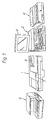
- Figure 2 is a partial view of the inside of the analyzer
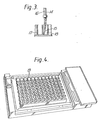
- Figure 3 shows the tip of the liquid dosimeter lowered to the bottom of a cuvette
- Figure 4 shows the thermostated incubator of the equipment.
- the main components of the equipment are an analyzer 1, a computer 2 with display terminal 3, and a printer 4. It is also possible to connect other control or data transfer and storage apparatuses 5 to the system.
- the analyzer has also an operating and output panel 6 of its own.
- the cover 7 of the analyzer is openable.
- the sample-cuvette set is placed on a mobile carriage 8.
- the path of movement of the carriage is rectilinear, denoted by the arrow shown at the end of the carriage.
- the direction of movement of the dosage head 9 is denoted with an arrow at the side of the head.
- the measurement is carried out by passing a beam of light from below through the hole 12 through the bottom of the sample cuvette so as to be detected via the measurement tip 13 of the photometer 10.
- liquid dosimeter 11 there is a main duct 14 connected to a tubing pump as well as a side duct 16 connected to a piston pump and opening into the said main duct (Fig. 3).
- the tip 15 of the liquid dosimeter can be lowered to the bottom of the cuvette placed underneath.
- the tip 15 of the liquid dosimeter 11 is made of a resilient material and is preferably curved (Fig. 3).
- Fig. 3 When the curved tip 15 is lowered to the bottom of a cuvette 18 in the cuvette set 17, the mouth of the tip becomes positioned in the corner of the cuvette 18. In this way it is possible to suck the liquid out of the cuvette 18 as completely as possible.
- a cuvette set 17 for vertical measurement which comprises a number of cylindrical measurement cuvettes 18 provided with transparent bottoms, which said cuvettes are interconnected at their top edges by means of a support plate so as to make a rectangular matrix.
- Antigen of the antibody to be determined has been attached to the inner walls of the cuvettes 18, in particular to their bottoms, in advance.
- the carriage 8 is provided with holes pervious to light facing the cuvettes 18.
- the carriage 8 is provided with a thermostated incubator, in which the cuvette set is placed.
- hte incubator there are heating pins 19 which become positioned between the cuvettes 18.
- the said pins 19 have a square section, whose sides are curved inwards following the walls of the cuvettes 18, so that a little gap remains between the pins 19 and the cuvettes (Fig. 4). In this way, air can circulate freely between the cuvettes, and the temperature in all the cuvettes remains as closely at the desired level as possible.
- the carriage 8 has a location 20 provided for the cuvette set 17, and so also a location 21 for the sample vessels as well as a location 22 for the necessary reagent and liquid-removal vessels.
- the equipment operates as follows:
- the cover 7 of the analyzer is opened, and the samples, such as serum samples, are placed in the location 21 provided for them, and the cuvette set 17 in the location 20 provided for it.
- the cover 7 is closed, and the desired program is started.
- the liquid dosimeter 11 fetches and dilutes each sample into its own cuvette 18 as well as fetches and measures the labelled antibody as well as any other reagents that may be required into each cuvette.
- the samples are incubated for the desired period of time, whereby the immunological reaction takes place.
- the liquid dosimeter 11 sucks the reaction solutions from all of the cuvettes 18 alternatingly into the main duct 14 and evacuates them into the vessel provided for them, while at the same time rinsing the duct. Now washing liquid is measured alternatingly into all of the cuvettes out of the main duct 14, whereupon the cuvettes are again emptied in the way described above. Finally, the amount of labelled antibody immobilized on the bottom of each cuvette is measured from the said bottoms, and the results of the assays are produced as an output in the desired way.
- the solution is removed from the cuvette so that the tip 15 is pushed onto the bottom of the cuvette 18, and when liquid is being sucked off, the curved tip 15 is shifted to against the corner of the cuvette. In this way the tip 15 is always placed precisely in the corner of the cuvette 18, and the solution can be removed as completely as possible.
- the washing liquid is measured into the cuvette 18 so that the liquid jet does not detach the reacted antibody, but, however, detaches any excess labelled antibody as well as any other impurities into the solution.
- the arrangement may, however, also be applied to fluorometric or radiological measurement.
- the equipment may also differ from that described above in other respects as regards its details. For example, it may have a separate incubation station, into which the carriage is driven.
- the dosage head may, of course, also be used during incubation, and so may the photometer.
Landscapes
- Chemical & Material Sciences (AREA)
- Health & Medical Sciences (AREA)
- General Health & Medical Sciences (AREA)
- Life Sciences & Earth Sciences (AREA)
- Analytical Chemistry (AREA)
- Biochemistry (AREA)
- Physics & Mathematics (AREA)
- General Physics & Mathematics (AREA)
- Immunology (AREA)
- Pathology (AREA)
- Clinical Laboratory Science (AREA)
- Chemical Kinetics & Catalysis (AREA)
- Apparatus Associated With Microorganisms And Enzymes (AREA)
- Automatic Analysis And Handling Materials Therefor (AREA)
Abstract
Description
- The present invention concerns a thermostated incubator which may be used generally for conducting photometric, fluorometric, phosphorimetric, or radiological immunoassays.
- In order to determine an antibody (or antigen) present in a sample, so-called heterogeneous immunoassay methods are used, wherein the antibody (or antigen) and an antibody (or antigen) labelled with a tracer are allowed to be immobilized on an antigen (or antibody, respectively) in advance placed on a solid face. In these methods, the solid face, on which the immunological reaction has taken place, and the reaction solution are separated from each other before the signal of the tracer is measured from the solid face, in order that the excess tracer present in the reaction solution should not cover the signal in the antibody (or antigen) immobilized on the solid phase. The signal concerned may be, for example, radioactivity (RIA), fluorescence activity (FIA), or enzyme activity (EIA). In all of these methods, the solid phase must be washed carefully before the measurement.
- The methods in use at present always include steps that must be performed manually; at least the washing step, for whose automation no means have been found that operate reliably in practice.
- In automatized methods, attempts must be made to use sets of reaction and measurement cuvettes consisting of several sample vessels. As a rule, the reactions must be carried out at a precisely determined temperature. For the control of the temperature, incubators have been used, which comprise a heatable piece and therein a cuvette-shaped recess of its own for each cuvette in the cuvette set. This solution is, however, not satisfactory, for in this way it is difficult to make the temperatures in the different cuvettes to remain sufficiently precisely at the desired level. Thus, as large cuvette sets cannot be used as would be advantageous in view of automation.
- DE-A-31 01 696 discloses an immunological assay equipment comprising a carriage displaceable in a horizontal plane, with said carriage including a location for a cuvette set, a dosage head displaceable above the carriage in a horizontal plane, a single-tip liquid dosimeter attached to the dosage head, whose tip can be lowered onto a cuvette placed underneath, and dosage equipment for removing the solution present in the cuvette through the tip. The dosage head. of this known equipment is displaceable only along a rectilinear path which is perpendicular to the rectilinear path of the carriage.
- US-A-3 951 605 also discloses an immunological assay equipment comprising a carriage in the form of a rack displaceable in a horizontal plane with the said carriage including a location for a set of test tubes, and further comprising a head movable in vertical direction and having a plurality of probes whose tips can be lowered into the test tubes, and finally comprising dosage equipment for passing liquid into and removing same from the test tubes.
- DE-A-28 17 330 discloses means and apparatus for analyzing of liquid samples and, more specifically, shows a thermostated incubator in the form of an aluminum block having a plurality of recesses designed to receive a plurality of correspondingly shaped test tubes and provided with a Peltier heating element for directly heating the aluminum block and the test tubes inserted into the recesses within the aluminum block.
- The object of the present invention is above all to provide a fully automatic heterogeneous immunological assay system. A particular object is to provide a system in which the heating and washing steps also take place automatically and reliably even when large cuvette sets are used.
- The apparatus now invented comprises: a cuvette-set carriage displaceable in the horizontal plane; a dosage head displaceable in the horizontal plane above the said carriage; a single-tip liquid dosimeter attached to the dosage head, which said dosimeter is provided with a tip that can be lowered to the bottom of the cuvette placed underneath; a dosage equipment for passing the desired liquid into the cuvette and for removing the solution placed in the cuvette out of the cuvette through the tip; as well as a measurement device attached to the dosage head.
- A preferred embodiment of the invention will be illustrated in more detail by means of the attached drawings. Therein Figure 1 is an overall illustration of the whole system, Figure 2 is a partial view of the inside of the analyzer, Figure 3 shows the tip of the liquid dosimeter lowered to the bottom of a cuvette, and Figure 4 shows the thermostated incubator of the equipment.
- The main components of the equipment are an analyzer 1, a computer 2 with display terminal 3, and a
printer 4. It is also possible to connect other control or data transfer and storage apparatuses 5 to the system. The analyzer has also an operating and output panel 6 of its own. The cover 7 of the analyzer is openable. The sample-cuvette set is placed on a mobile carriage 8. The path of movement of the carriage is rectilinear, denoted by the arrow shown at the end of the carriage. Above the carriage 8, there is a dosage head 9 displaceable along a path perpendicular to the path of movement of the carriage, to which said dosage head aphotometer 10 and a liquid dosimeter 11 are attached. The direction of movement of the dosage head 9 is denoted with an arrow at the side of the head. - The measurement is carried out by passing a beam of light from below through the
hole 12 through the bottom of the sample cuvette so as to be detected via themeasurement tip 13 of thephotometer 10. - In the liquid dosimeter 11 there is a
main duct 14 connected to a tubing pump as well as aside duct 16 connected to a piston pump and opening into the said main duct (Fig. 3). Thetip 15 of the liquid dosimeter can be lowered to the bottom of the cuvette placed underneath. - The
tip 15 of the liquid dosimeter 11 is made of a resilient material and is preferably curved (Fig. 3). When thecurved tip 15 is lowered to the bottom of acuvette 18 in thecuvette set 17, the mouth of the tip becomes positioned in the corner of thecuvette 18. In this way it is possible to suck the liquid out of thecuvette 18 as completely as possible. - In the analyzer, a cuvette set 17 for vertical measurement is used, which comprises a number of
cylindrical measurement cuvettes 18 provided with transparent bottoms, which said cuvettes are interconnected at their top edges by means of a support plate so as to make a rectangular matrix. Antigen of the antibody to be determined has been attached to the inner walls of thecuvettes 18, in particular to their bottoms, in advance. The carriage 8 is provided with holes pervious to light facing thecuvettes 18. - The carriage 8 is provided with a thermostated incubator, in which the cuvette set is placed. In hte incubator, there are
heating pins 19 which become positioned between thecuvettes 18. The saidpins 19 have a square section, whose sides are curved inwards following the walls of thecuvettes 18, so that a little gap remains between thepins 19 and the cuvettes (Fig. 4). In this way, air can circulate freely between the cuvettes, and the temperature in all the cuvettes remains as closely at the desired level as possible. - The carriage 8 has a
location 20 provided for the cuvette set 17, and so also alocation 21 for the sample vessels as well as alocation 22 for the necessary reagent and liquid-removal vessels. - The equipment operates as follows:
- The cover 7 of the analyzer is opened, and the samples, such as serum samples, are placed in the
location 21 provided for them, and the cuvette set 17 in thelocation 20 provided for it. The cover 7 is closed, and the desired program is started. The liquid dosimeter 11 fetches and dilutes each sample into itsown cuvette 18 as well as fetches and measures the labelled antibody as well as any other reagents that may be required into each cuvette. The samples are incubated for the desired period of time, whereby the immunological reaction takes place. - Now the liquid dosimeter 11 sucks the reaction solutions from all of the
cuvettes 18 alternatingly into themain duct 14 and evacuates them into the vessel provided for them, while at the same time rinsing the duct. Now washing liquid is measured alternatingly into all of the cuvettes out of themain duct 14, whereupon the cuvettes are again emptied in the way described above. Finally, the amount of labelled antibody immobilized on the bottom of each cuvette is measured from the said bottoms, and the results of the assays are produced as an output in the desired way. - The solution is removed from the cuvette so that the
tip 15 is pushed onto the bottom of thecuvette 18, and when liquid is being sucked off, thecurved tip 15 is shifted to against the corner of the cuvette. In this way thetip 15 is always placed precisely in the corner of thecuvette 18, and the solution can be removed as completely as possible. - The washing liquid is measured into the
cuvette 18 so that the liquid jet does not detach the reacted antibody, but, however, detaches any excess labelled antibody as well as any other impurities into the solution. - Above, a preferred photometric embodiment has been described. The arrangement may, however, also be applied to fluorometric or radiological measurement. The equipment may also differ from that described above in other respects as regards its details. For example, it may have a separate incubation station, into which the carriage is driven. The dosage head may, of course, also be used during incubation, and so may the photometer.
- In an advantageous embodiment, several different assay sequences are carried out at the same time.
Claims (4)
Priority Applications (1)
| Application Number | Priority Date | Filing Date | Title |
|---|---|---|---|
| EP19900106878 EP0402588A3 (en) | 1985-10-07 | 1986-10-07 | Incubator |
Applications Claiming Priority (3)
| Application Number | Priority Date | Filing Date | Title |
|---|---|---|---|
| FI853895 | 1985-10-07 | ||
| FI853895A FI853895A0 (en) | 1985-10-07 | 1985-10-07 | IMMUNOLOGISKT BESTAEMNINGSSYSTEM. |
| EP19900106878 EP0402588A3 (en) | 1985-10-07 | 1986-10-07 | Incubator |
Related Parent Applications (2)
| Application Number | Title | Priority Date | Filing Date |
|---|---|---|---|
| EP86905832A Division EP0238582B1 (en) | 1985-10-07 | 1986-10-07 | Method for immunological determinations |
| EP86905832.1 Division | 1986-10-07 |
Publications (2)
| Publication Number | Publication Date |
|---|---|
| EP0402588A2 true EP0402588A2 (en) | 1990-12-19 |
| EP0402588A3 EP0402588A3 (en) | 1991-07-10 |
Family
ID=26125100
Family Applications (1)
| Application Number | Title | Priority Date | Filing Date |
|---|---|---|---|
| EP19900106878 Ceased EP0402588A3 (en) | 1985-10-07 | 1986-10-07 | Incubator |
Country Status (1)
| Country | Link |
|---|---|
| EP (1) | EP0402588A3 (en) |
Cited By (3)
| Publication number | Priority date | Publication date | Assignee | Title |
|---|---|---|---|---|
| FR2726653A1 (en) * | 1994-11-07 | 1996-05-10 | Armines | Rotary-plate appts. for collection or distribution of liq. samples |
| WO2002093169A1 (en) * | 2001-05-17 | 2002-11-21 | Bayer Healthcare Llc | Assay test system for regulating temperature |
| US7285425B2 (en) | 2002-05-14 | 2007-10-23 | Siemens Medical Solutions Diagnostics | Assay test system for regulating temperature |
Citations (3)
| Publication number | Priority date | Publication date | Assignee | Title |
|---|---|---|---|---|
| US3951605A (en) | 1974-08-08 | 1976-04-20 | Rohe Scientific Corporation | Instrument for automated immunochemical analysis |
| DE2817330A1 (en) | 1977-04-22 | 1978-10-26 | Vitatron Scientific Bv | DEVICE FOR THE ANALYSIS OF LIQUID SAMPLES |
| DE3101696A1 (en) | 1981-01-21 | 1982-08-19 | Behringwerke Ag, 3550 Marburg | "Appliance for drawing samples from regularly arranged sample containers" |
Family Cites Families (4)
| Publication number | Priority date | Publication date | Assignee | Title |
|---|---|---|---|---|
| US3260413A (en) * | 1964-08-31 | 1966-07-12 | Scientific Industries | Automatic chemical analyzer |
| DE2703428A1 (en) * | 1977-01-28 | 1978-08-03 | Klaus F Mueller | Temp. controlled cuvette holder - has thermostat with heaters in each cuvette chamber, pressed to partition |
| US4299796A (en) * | 1977-04-22 | 1981-11-10 | Vitatron Scientific B.V. | Apparatus for performing tests and measurements on liquid samples |
| DE3441179A1 (en) * | 1984-11-10 | 1986-05-22 | Dynatech Deutschland GmbH, 7306 Denkendorf | Temperature-control device for microcell arrangements, in particular microtitration plates |
-
1986
- 1986-10-07 EP EP19900106878 patent/EP0402588A3/en not_active Ceased
Patent Citations (3)
| Publication number | Priority date | Publication date | Assignee | Title |
|---|---|---|---|---|
| US3951605A (en) | 1974-08-08 | 1976-04-20 | Rohe Scientific Corporation | Instrument for automated immunochemical analysis |
| DE2817330A1 (en) | 1977-04-22 | 1978-10-26 | Vitatron Scientific Bv | DEVICE FOR THE ANALYSIS OF LIQUID SAMPLES |
| DE3101696A1 (en) | 1981-01-21 | 1982-08-19 | Behringwerke Ag, 3550 Marburg | "Appliance for drawing samples from regularly arranged sample containers" |
Cited By (3)
| Publication number | Priority date | Publication date | Assignee | Title |
|---|---|---|---|---|
| FR2726653A1 (en) * | 1994-11-07 | 1996-05-10 | Armines | Rotary-plate appts. for collection or distribution of liq. samples |
| WO2002093169A1 (en) * | 2001-05-17 | 2002-11-21 | Bayer Healthcare Llc | Assay test system for regulating temperature |
| US7285425B2 (en) | 2002-05-14 | 2007-10-23 | Siemens Medical Solutions Diagnostics | Assay test system for regulating temperature |
Also Published As
| Publication number | Publication date |
|---|---|
| EP0402588A3 (en) | 1991-07-10 |
Similar Documents
| Publication | Publication Date | Title |
|---|---|---|
| JP3453573B2 (en) | Automatic continuous random access analysis system and its components | |
| EP0238582B1 (en) | Method for immunological determinations | |
| US4681742A (en) | Assay tray | |
| EP0089346B1 (en) | Automated immunoassay system | |
| EP0212663B1 (en) | Automated immunoassay analyser | |
| US4952518A (en) | Automated assay machine and assay tray | |
| JP4209651B2 (en) | Method for modeling tests performed by instrumentation software used in continuous analysis systems | |
| EP1870713B1 (en) | Apparatus for multiple automatic analysis of biosamples, method for autoanalysis, and reaction cuvette | |
| EP1102994B1 (en) | Automated immunoassay apparatus with flexible pick-up arm | |
| EP0681699B1 (en) | Solid phase immunoassay with carriers matching the shape of sample wells | |
| GB2199407A (en) | Automated patient sample analysis instrument | |
| US5063024A (en) | Method and apparatus for immunological determinations | |
| ATE60446T1 (en) | REAGENT CONTAINER SYSTEM FOR A CLINICAL ANALYZER. | |
| EP0402588A2 (en) | Incubator | |
| EP0336309A2 (en) | A selective or sequential access analyzer for clinico-chemical analyses and for immunological tests | |
| US5324479A (en) | Analyzer for the determination of the phenotype and the ABO blood group | |
| JP2566416B2 (en) | Clinical chemistry analyzer and analyzer used therefor | |
| EP0497019B1 (en) | Automatic immunological analysing system | |
| JPH06288916A (en) | Biochemically analyzing method | |
| FI92020C (en) | incubator | |
| FI91808B (en) | Immunological determination system | |
| JPS63106567A (en) | Pipet apparatus having automatic nozzle tip replacing mechanism | |
| JPS5951358A (en) | Automatic analyzer | |
| JPS6315163A (en) | Immunological analyzer |
Legal Events
| Date | Code | Title | Description |
|---|---|---|---|
| PUAI | Public reference made under article 153(3) epc to a published international application that has entered the european phase |
Free format text: ORIGINAL CODE: 0009012 |
|
| 17P | Request for examination filed |
Effective date: 19900410 |
|
| AC | Divisional application: reference to earlier application |
Ref document number: 238582 Country of ref document: EP |
|
| AK | Designated contracting states |
Kind code of ref document: A2 Designated state(s): DE FR GB IT |
|
| PUAL | Search report despatched |
Free format text: ORIGINAL CODE: 0009013 |
|
| AK | Designated contracting states |
Kind code of ref document: A3 Designated state(s): DE FR GB IT |
|
| 17Q | First examination report despatched |
Effective date: 19930709 |
|
| STAA | Information on the status of an ep patent application or granted ep patent |
Free format text: STATUS: THE APPLICATION HAS BEEN REFUSED |
|
| 18R | Application refused |
Effective date: 19950217 |