EP0402242A1 - Mirror unit for a sun visor, notably in a passengeer compartment of an automobile - Google Patents
Mirror unit for a sun visor, notably in a passengeer compartment of an automobile Download PDFInfo
- Publication number
- EP0402242A1 EP0402242A1 EP90401527A EP90401527A EP0402242A1 EP 0402242 A1 EP0402242 A1 EP 0402242A1 EP 90401527 A EP90401527 A EP 90401527A EP 90401527 A EP90401527 A EP 90401527A EP 0402242 A1 EP0402242 A1 EP 0402242A1
- Authority
- EP
- European Patent Office
- Prior art keywords
- cassette
- flap
- stop element
- rear face
- pins
- Prior art date
- Legal status (The legal status is an assumption and is not a legal conclusion. Google has not performed a legal analysis and makes no representation as to the accuracy of the status listed.)
- Granted
Links
Images

Classifications
-
- B—PERFORMING OPERATIONS; TRANSPORTING
- B60—VEHICLES IN GENERAL
- B60J—WINDOWS, WINDSCREENS, NON-FIXED ROOFS, DOORS, OR SIMILAR DEVICES FOR VEHICLES; REMOVABLE EXTERNAL PROTECTIVE COVERINGS SPECIALLY ADAPTED FOR VEHICLES
- B60J3/00—Antiglare equipment associated with windows or windscreens; Sun visors for vehicles
- B60J3/02—Antiglare equipment associated with windows or windscreens; Sun visors for vehicles adjustable in position
- B60J3/0204—Sun visors
- B60J3/0278—Sun visors structure of the body
- B60J3/0282—Sun visors structure of the body specially adapted for a courtesy mirror
Definitions
- the invention relates to a mirror cassette for a sun visor comprising a flap which is articulated on the cassette so that it can pivot between a closed position in which the flap covers the mirror and an open position in which the mirror is released, and which is locked in the open and closed positions by stop devices consisting of a fixed stop element formed on the cassette and a movable stop element moving with the shutter .
- German patent application DE-OS 37 03 511 a mirror cassette is known on which the articulation of the flap on the cassette is produced by means of pins mounted axially sliding in a bore formed on the flap and cooperating with cavities forming bearings provided in correspondence on the cassette.
- the flap is locked in the open and closed position using cooperating projections formed concentrically with the pivot axis, one of which is fixed and formed on the cassette, and the other being formed on the external end of the corresponding stud.
- a compression spring is provided so that the projection of the stud is firmly engaged with the corresponding projection of the cavity.
- French patent application 88 04 457 describes another cassette in which the pins of the joint are formed on the lateral edges of the cassette and cooperate with corresponding cavities formed on the edges of the flap.
- the shutter manufacturing mold requires retractable drawers for the formation of the cavities forming bearings and that, on the other hand, the mounting of the flap on the housing requires introducing one of the nipples into the corresponding cavity, then deforming by elasticity the flap so as to introduce the second stud force in its cavity, which can result in breaks, either of the flap or of a nipple.
- This mounting operation is all the more difficult as the flap is small and rigid.
- the shutter has cavities forming bearings and the cassette has pins cooperating with the bearings and in which the movable stop element of the shutter is constituted by a V-shaped edge.
- the fixed stop element of the cassette consists of a spring leaf applying to the flap a force directed towards the front face of the housing.
- the object of the present invention is to overcome these drawbacks and to propose a mirror cassette of the type mentioned above which, on the one hand, is easy to assemble, and which, on the other hand, eliminates the need for provide retractable drawers in the molds for manufacturing the housing and / or the cover, thereby making it possible to reduce the cost of the molds and increase the rate of manufacture of the molded parts.
- the articulation of the flap on the cassette comprises two aligned pins, parallel to one side of the flap, formed respectively on the lateral edges of the flap in the vicinity of said side and extending towards the outside of the flap, that the cassette has near its longitudinal upper edge a passage slot, intended to allow the mounting of the flap by the rear face of the cassette, which has a width at least equal to the thickness of the flap and a length at least equal to the distance separating the opposite edges of the flap carrying said pins and which has in each of its lateral end zones an open excavation on the side of the rear face of the cassette and intended to form a half-bearing for a stud of said flap and that the cassette is provided with at least one stirrup which is in abutment on the edge of the flap close to the alignment of said studs so as to maintain said studs in their respective half-bearings.
- the cavity forming a bearing of the prior art is replaced by the wall of the cassette on which the stud is resting and by the bracket holding the flap.
- the molds for manufacturing the cassette and the flap no longer require retractable drawers for the formation of the cavities, which makes it possible to increase the rate of use of these molds and to reduce the manufacturing cost thereof.
- the mounting of the flap on the housing is simplified. The edge of the shutter remote from the hinge axis is presented in the slot by the rear face of the housing and the shutter is made to slide in said slot until the pins are in abutment in the excavations. You can place the box horizontally with its rear side facing upwards and drop the shutter into the slot. Then just fix the bracket (s) to hold the shutter.
- the stirrup is constituted by an elastic blade which exerts on the flap a force directed towards the front face of the cassette. This arrangement avoids rattling of the shutter when the cassette is subjected to vibrations.
- the edge of the flap close to the alignment of the pins has at least one transverse movable stop element constituted by a V-shaped edge situated between two flats and the stirrup cooperates with said movable stop element and forms the fixed stop element of a stop device. Thanks to this structure, the manufacturing cost of the cassette is lower.
- the stirrup has the shape of a U, one end branch of which accommodates in a cavity formed in the cassette and opening onto the rear face of the latter, and the other end branch of which is free and cooperates. with the movable stop element.
- the cassette comprises two stirrups arranged in the vicinity of the lateral edges of the flap.
- the excavation has a semi-circular groove conforming to the corresponding stud and the wall of which is extended by two flat walls which deviate slightly towards the rear face of the cassette.
- the groove plays the role of a half-bearing for the corresponding stud, and the flared shape of the excavation facilitates the introduction of the flap during the mounting phase, thanks to the guidance of the studs by the flat walls.
- the cassette has a side wall opposite the end of each stud. This side wall increases the rigidity of the cassette.
- FIG. 1A shows a mirror cassette 2 embedded in a sun visor 1.
- Cassette 2 contains a mirror or glass 4 which can be covered by a pivotally mounted flap 3.
- the shutter 3 occupies its open position in FIG. 1A.
- Cassette 2 can additionally contain, but is not compulsory, lighting devices 5, for example in the form of small bulbs covered by an opal glass slide.
- Figure 1B shows the sun visor 1 with the flap 3 of the cassette 2 in the closed position.
- the shutter 3 has a flat or slightly curved outer face 6 and has a bead 7 on the periphery of its internal face which lodges in a groove 8 of rectangular shape formed near the periphery of the front face 9 of the cassette 2, when the shutter 3 is folded down.
- the flap 3 can pivot around a pivot axis 10 located in the vicinity of the longitudinal upper edge of the cassette 2 in the corresponding part of the groove 8.
- the male elements of the articulation of the flap 3 on the cassette 2 are constituted by two pins 12 aligned and parallel to the edge 21 of the flap 3 near the upper longitudinal edge of the cassette 2, which are formed respectively on the lateral edges 11 of the flap 3 perpendicular to the edge 21.
- the pins 12 are in the vicinity of this edge 21 and extend towards the outside of the shutter 3. They at least partially lodge in housings forming half-bearings provided in the opposite edges 13 of the cassette and opening into the groove.
- FIG. 2 shows a view of the front face of the cassette 2 without the flap 3 and having no lighting devices 5.
- the cassette 2 has in the vicinity of the pivot axis 10 a slot 14 which has a width at least equal to the thickness of the flap 3.
- the slot 14 opens on the front face 9 of the cassette 2 through an orifice 14a having a length at least equal to the length of the flap 3 between the two pins 12 and opens onto the rear face 15 of the cassette 2 through an orifice 15b having a length at least equal to the distance separating the free ends 16 of the two pins 12.
- the slot 14 can be opened opposite the ends 16 of the pins 12 and on the side of the lateral faces 17 of the cassette 2 (FIG. 7), but preferably the lateral faces 17 are closed off at the ends 16 of the pins 12 by walls 17a which reinforce the rigidity of the cassette 2.
- each stud 12 is formed by a semi-cylindrical groove 18 delimited by the wall 18a of the corresponding edge 13 of the cassette 2 located near the stud 12 and on the side of the front face 9 of the cassette 2 relative to the pivot axis 10.
- This semi-cylindrical groove 18 is open on the side of the rear face 15 of the cassette 2 by virtue of flat walls 19 and 20 which extend the wall 18a, which delimit the end part of the slot 14 and which slightly deviate towards the rear face 15.
- the slot 14 thus has, in each of its zones adjacent to the studs 12, an excavation 20a opening onto the rear face 15 of the cavity 29 in the orifice 14b.
- the shutter 3 is mounted on the cassette 2 by presenting its edge remote from the studs 12 in the orifice 14b on the side of the rear face 15 of the cassette 2, then by sliding it into the slot 14 until the studs 12 are housed in their respective grooves 18.
- the edge 21 of the flap 3 adjacent to the pivot axis 10 comprises on the bead 7 adjacent a V-shaped edge 22 having two flats 23 and 24 which can be in contact, alternately, depending on the opening or closing position of the shutter 3, with a free end branch 25 of a metal blade 26, forming a spring and in the shape of a U, the second end branch 27 of this elastic blade 26 being fixed in a cavity 29 provided in the wall of the cassette 2 adjacent to the pivot axis 10 and opening onto the rear face 15, using latching means.
- the elastic blade 26 thus forms a stirrup which maintains the pins 12 of the flap 3 in their respective grooves 18.
- the elastic blade 26 exerts on the flap 3 via the flats 23 or 24 a force directed towards the front face 9 of the cassette 2, which eliminates vibrations and rattling of the flap 3 when the vehicle passes through the potholes.
- the elastic blade 26 in cooperation with the flats 23 and 24 constitutes a device for stopping the flap 3 at the positions of closing and opening, the free end branch 25 of the elastic blade 26 forming the fixed stop element and the edge 22 in combination with the flats 23 and 24 forming the movable stop element with the flap 3.
- two stop devices are provided, each of them being arranged in the vicinity of one of the lateral edges 11 of the shutter 3.
- the elastic blade 26 constitutes both the fixed stop element and the bracket for holding the shutter 3 on the cassette 2 preventing the shutter 3 from escaping. It goes without saying that the shutter 3 can be maintained around its pivot axis 10, using a bracket independent of the stop device and fixed on the cassette 2, in the vicinity of the axis of pivot 10 and on the side of the rear face 15 of the cassette. This stirrup can be placed in the vicinity of a stud 12 or in the vicinity of the edge 21 of the cassette 2.
Abstract
Description
L'invention concerne une cassette à miroir pour un pare-soleil comprenant un volet qui est articulé sur la cassette de telle manière qu'il puisse pivoter entre une position de fermeture dans laquelle le volet recouvre le miroir et une position d'ouverture dans laquelle le miroir est dégagé, et qui est bloqué aux positions d'ouverture et de fermeture par des dispositifs d'arrêt constitués d'un élément d'arrêt fixe formé sur la cassette et d'un élément d'arrêt mobile se déplaçant avec le volet.The invention relates to a mirror cassette for a sun visor comprising a flap which is articulated on the cassette so that it can pivot between a closed position in which the flap covers the mirror and an open position in which the mirror is released, and which is locked in the open and closed positions by stop devices consisting of a fixed stop element formed on the cassette and a movable stop element moving with the shutter .
Par la demande de brevet allemand DE-OS 37 03 511, on connaît une cassette à miroir sur laquelle l'articulation du volet sur la cassette est réalisée à l'aide de tétons montés axialement coulissants dans un alésage formé sur le volet et coopérant avec des cavités formant paliers prévues en correspondance sur la cassette. Le volet est bloqué en position d'ouverture et de fermeture à l'aide de saillies coopérantes formées concentriquement à l'axe de pivotement, l'une d'elles étant fixe et formée sur la cassette, et l'autre étant formée sur l'extrémité externe du téton correspondant. Un ressort de compression est prévu pour que la saillie du téton soit fermement en prise avec la saillie correspondante de la cavité.By German patent application DE-OS 37 03 511, a mirror cassette is known on which the articulation of the flap on the cassette is produced by means of pins mounted axially sliding in a bore formed on the flap and cooperating with cavities forming bearings provided in correspondence on the cassette. The flap is locked in the open and closed position using cooperating projections formed concentrically with the pivot axis, one of which is fixed and formed on the cassette, and the other being formed on the external end of the corresponding stud. A compression spring is provided so that the projection of the stud is firmly engaged with the corresponding projection of the cavity.
L'inconvénient de cette cassette connue est la fabrication et le montage difficiles des différentes pièces. Les alésages du volet et les cavités formant paliers nécessitent de prévoir des tiroirs rétractables dans les moules de fabrication de la cassette ou du volet, ce qui augmente le coût des moules et diminue la cadence de fabrication. De plus, il s'avère particulièrement difficile et laborieux d'incorporer le ressort de compression, celui-ci devant être monté à l'état comprimé.The disadvantage of this known cassette is the difficult manufacture and assembly of the different parts. The bores of the flap and the cavities forming bearings require the provision of retractable drawers in the molds for manufacturing the cassette or the flap, which increases the cost of the molds and decreases the rate of manufacture. In addition, it proves to be particularly difficult and laborious to incorporate the compression spring, the latter having to be mounted in the compressed state.
La demande de brevet français 88 04 457 décrit une autre cassette dans laquelle les tétons de l'articulation sont formés sur les bords latéraux de la cassette et coopèrent avec des cavités correspondantes ménagées sur les bords du volet.French patent application 88 04 457 describes another cassette in which the pins of the joint are formed on the lateral edges of the cassette and cooperate with corresponding cavities formed on the edges of the flap.
L'inconvénient de cette cassette est que, d'une part, le moule de fabrication du volet nécessite des tiroirs rétractables pour la formation des cavités formant paliers et que, d'autre part, le montage du volet sur le boîtier nécessite d'introduire l'un des tétons dans la cavité correspondante, puis de déformer par élasticité le volet de manière à introduire le deuxième téton de force dans sa cavité, ce qui peut se traduire par des cassures, soit du volet, soit d'un téton. Cette opération de montage est d'autant plus difficile que le volet est petit et rigide.The disadvantage of this cassette is that, on the one hand, the shutter manufacturing mold requires retractable drawers for the formation of the cavities forming bearings and that, on the other hand, the mounting of the flap on the housing requires introducing one of the nipples into the corresponding cavity, then deforming by elasticity the flap so as to introduce the second stud force in its cavity, which can result in breaks, either of the flap or of a nipple. This mounting operation is all the more difficult as the flap is small and rigid.
On trouve également dans le commerce une cassette à miroir dans laquelle le volet comporte des cavités formant paliers et la cassette présente des tétons coopérant avec les paliers et dans laquelle l'élément d'arrêt mobile du volet est constitué par une arête en forme de V prévue sur le bord du volet voisin de l'alignement des cavités, et l'élément d'arrêt fixe de la cassette est constitué d'une lame à ressort appliquant sur le volet une force dirigée vers la face avant du boîtier.There is also commercially available a mirror cassette in which the shutter has cavities forming bearings and the cassette has pins cooperating with the bearings and in which the movable stop element of the shutter is constituted by a V-shaped edge. provided on the edge of the flap close to the alignment of the cavities, and the fixed stop element of the cassette consists of a spring leaf applying to the flap a force directed towards the front face of the housing.
Cette cassette connue présente les inconvénients de la cassette décrite dans la demande de brevet français no 88 04 547.This known cassette has the drawbacks of the tape described in French patent application No. 88 04 547.
Le but de la présente invention est de pallier ces inconvénients et de proposer une cassette à miroir du type mentionné ci-dessus qui, d'une part, soit d'un montage aisé, et qui, d'autre part, élimine la nécessité de prévoir des tiroirs rétractables dans les moules de fabrication du boîtier et/ou du couvercle, permettant ainsi de diminuer le coût des moules et d'augmenter la cadence de fabrication des pièces moulées.The object of the present invention is to overcome these drawbacks and to propose a mirror cassette of the type mentioned above which, on the one hand, is easy to assemble, and which, on the other hand, eliminates the need for provide retractable drawers in the molds for manufacturing the housing and / or the cover, thereby making it possible to reduce the cost of the molds and increase the rate of manufacture of the molded parts.
Le but est atteint selon l'invention par le fait
que l'articulation du volet sur la cassette comporte deux tétons alignés, parallèles à un côté du volet, formés respectivement sur les bords latéraux du volet au voisinage dudit côté et s'étendant vers l'extérieur du volet,
que la cassette présente près de son bord supérieur longitudinal une fente de passage, destinée à permettre le montage du volet par la face arrière de la cassette, qui a une largeur au moins égale à l'épaisseur du volet et une longueur au moins égale à la distance séparant les bords opposés du volet portant lesdits tétons et qui présente dans chacune de ses zones d'extrémité latérales une excavation ouverte du côté de la face arrière de la cassette et destinée à former un demi-palier pour un téton dudit volet
et que la cassette est munie d'au moins un étrier qui est en appui sur le bord de volet voisin de l'alignement desdits tétons de manière à maintenir lesdits tétons dans leurs demi-paliers respectifs.The object is achieved according to the invention by the fact
that the articulation of the flap on the cassette comprises two aligned pins, parallel to one side of the flap, formed respectively on the lateral edges of the flap in the vicinity of said side and extending towards the outside of the flap,
that the cassette has near its longitudinal upper edge a passage slot, intended to allow the mounting of the flap by the rear face of the cassette, which has a width at least equal to the thickness of the flap and a length at least equal to the distance separating the opposite edges of the flap carrying said pins and which has in each of its lateral end zones an open excavation on the side of the rear face of the cassette and intended to form a half-bearing for a stud of said flap
and that the cassette is provided with at least one stirrup which is in abutment on the edge of the flap close to the alignment of said studs so as to maintain said studs in their respective half-bearings.
Grâce à cette structure, la cavité formant palier de l'art antérieur est remplacée par la paroi de la cassette sur laquelle le téton est en appui et par l'étrier maintenant le volet. Les moules de fabrication de la cassette et du volet ne nécessitent plus de tiroirs rétractables pour la formation des cavités, ce qui permet d'augmenter la cadence d'utilisation de ces moules et d'en diminuer le coût de fabrication. De plus, le montage du volet sur le boîtier est simplifié. Le bord du volet éloigné de l'axe d'articulation est présenté dans la fente par la face arrière du boîtier et on fait coulisser le volet dans ladite fente jusqu'à ce que les tétons soient en butée dans les excavations. On peut disposer le boîtier à l'horizontale avec sa face arrière dirigée vers le haut et laisser tomber le volet dans la fente. Il suffit ensuite de fixer le ou les étriers pour maintenir le volet.Thanks to this structure, the cavity forming a bearing of the prior art is replaced by the wall of the cassette on which the stud is resting and by the bracket holding the flap. The molds for manufacturing the cassette and the flap no longer require retractable drawers for the formation of the cavities, which makes it possible to increase the rate of use of these molds and to reduce the manufacturing cost thereof. In addition, the mounting of the flap on the housing is simplified. The edge of the shutter remote from the hinge axis is presented in the slot by the rear face of the housing and the shutter is made to slide in said slot until the pins are in abutment in the excavations. You can place the box horizontally with its rear side facing upwards and drop the shutter into the slot. Then just fix the bracket (s) to hold the shutter.
Avantageusement, l'étrier est constitué par une lame élastique qui exerce sur le volet une force dirigée vers la face avant de la cassette. Cette disposition évite les cliquetis du volet lorsque la cassette est soumise à des vibrations.Advantageously, the stirrup is constituted by an elastic blade which exerts on the flap a force directed towards the front face of the cassette. This arrangement avoids rattling of the shutter when the cassette is subjected to vibrations.
Avantageusement, le bord du volet voisin de l'alignement des tétons présente au moins un élément d'arrêt mobile transversal constitué d'une arête en forme de V située entre deux méplats et l'étrier coopère avec ledit élément d'arrêt mobile et forme l'élément d'arrêt fixe d'un dispositif d'arrêt. Grâce à cette structure, le coût de fabrication de la cassette est moindre.Advantageously, the edge of the flap close to the alignment of the pins has at least one transverse movable stop element constituted by a V-shaped edge situated between two flats and the stirrup cooperates with said movable stop element and forms the fixed stop element of a stop device. Thanks to this structure, the manufacturing cost of the cassette is lower.
Avantageusement, l'étrier a la forme d'un U dont une branche d'extrémité loge dans une cavité ménagée dans la cassette et débouchant sur la face arrière de celle-ci, et dont l'autre branche d'extrémité est libre et coopère avec l'élément d'arrêt mobile.Advantageously, the stirrup has the shape of a U, one end branch of which accommodates in a cavity formed in the cassette and opening onto the rear face of the latter, and the other end branch of which is free and cooperates. with the movable stop element.
De préférence, la cassette comporte deux étriers disposés au voisinage des bords latéraux du volet.Preferably, the cassette comprises two stirrups arranged in the vicinity of the lateral edges of the flap.
Avantageusement, l'excavation présente une gorge semi-circulaire conformée au téton correspondant et dont la paroi est prolongée par deux parois planes qui s'écartent légèrement vers la face arrière de la cassette. La gorge joue le rôle d'un demi-palier pour le téton correspondant, et la forme évasée de l'excavation facilite l'introduction du volet pendant la phase de montage, grâce au guidage des tétons par les parois planes.Advantageously, the excavation has a semi-circular groove conforming to the corresponding stud and the wall of which is extended by two flat walls which deviate slightly towards the rear face of the cassette. The groove plays the role of a half-bearing for the corresponding stud, and the flared shape of the excavation facilitates the introduction of the flap during the mounting phase, thanks to the guidance of the studs by the flat walls.
De préférence, la cassette comporte une paroi latérale en regard de l'extrémité de chaque téton. Cette paroi latérale augmente la rigidité de la cassette.Preferably, the cassette has a side wall opposite the end of each stud. This side wall increases the rigidity of the cassette.
D'autres avantages et caractéristiques de l'invention ressortiront à la lecture d'un mode de réalisation décrit ci-après à titre d'exemple non limitatif et en référence au dessin annexé dans lequel :
- - la figure 1A montre un pare-soleil avec une cassette à miroir dont le volet est relevé ;
- - la figure 1B montre un pare-soleil avec une cassette à miroir fermée par le volet ;
- - la figure 2 est une vue de la face avant d'une deuxième cassette à miroir sans le volet ;
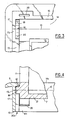
- - la figure 3 est une vue à plus grande échelle d'un coin de la face arrière de la cassette à miroir sans le volet ;
- - la figure 4 est une coupe à plus grande échelle selon la ligne IV-IV de la figure 2 et de la figure 6, montrant la région de l'axe de pivotement, le volet étant ouvert ;
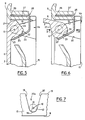
- - la figure 5 est une coupe à plus grande échelle de la région de l'axe de pivotement de la cassette avec le volet en position de fermeture selon la ligne V-V de la figure 2 ;
- - la figure 6 est une coupe semblable avec le volet en position d'ouverture ; et
- - la figure 7 montre à grande échelle le logement d'un téton.
- - Figure 1A shows a sun visor with a mirror cassette whose flap is raised;
- - Figure 1B shows a sun visor with a mirror cassette closed by the flap;
- - Figure 2 is a view of the front face of a second mirror cassette without the flap;
- - Figure 3 is an enlarged view of a corner of the rear face of the mirror cassette without the flap;
- - Figure 4 is a section on a larger scale along the line IV-IV of Figure 2 and Figure 6, showing the region of the pivot axis, the flap being open;
- - Figure 5 is a section on a larger scale of the region of the pivot axis of the cassette with the flap in the closed position along line VV of Figure 2;
- - Figure 6 is a similar section with the flap in the open position; and
- - Figure 7 shows on a large scale the housing of a stud.
La figure 1A montre une cassette à miroir 2 encastrée dans un pare-soleil 1. La cassette 2 contient un miroir ou glace 4 qui peut être recouvert par un volet 3 monté pivotant. Le volet 3 occupe sa position d'ouverture sur la figure 1A. La cassette 2 peut contenir en plus, mais ce n'est pas obligatoire, des dispositifs d'éclairage 5, par exemple sous forme de petites ampoules recouvertes par une lame de verre opale. La figure 1B montre le pare-soleil 1 avec le volet 3 de la cassette 2 en position de fermeture. Le volet 3 présente une face externe 6 plane ou légèrement bombée et présente un bourrelet 7 sur le pourtour de sa face interne qui loge dans une rainure 8 de forme rectangulaire ménagée près du pourtour de la face avant 9 de la cassette 2, lorsque le volet 3 est rabattu. Le volet 3 peut pivoter autour d'un axe de pivotement 10 situé au voisinage du bord supérieur longitudinal de la cassette 2 dans la partie correspondante de la rainure 8.Figure 1A shows a
Les éléments mâles de l'articulation du volet 3 sur la cassette 2 sont constitués par deux tétons 12 alignés et parallèles au bord 21 du volet 3 voisin du bord supérieur longitudinal de la cassette 2, qui sont formés respectivement sur les bords latéraux 11 du volet 3 perpendiculaires au bord 21. Les tétons 12 sont au voisinage de ce bord 21 et s'étendent vers l'extérieur du volet 3. Ils logent au moins partiellement dans des logements formant demi-paliers prévus dans les bords opposés 13 de la cassette et débouchant dans la rainure.The male elements of the articulation of the
La figure 2 montre une vue de la face avant de la cassette 2 sans le volet 3 et ne comportant pas de dispositifs d'éclairage 5. Comme on le voit sur cette figure ét les figures suivantes, la cassette 2 présente au voisinage de l'axe de pivotement 10 une fente 14 qui a une largeur au moins égale à l'épaisseur du volet 3. La fente 14 débouche sur la face avant 9 de la cassette 2 par un orifice 14a ayant une longueur au moins égale à la longueur du volet 3 comprise entre les deux tétons 12 et débouche sur la face arrière 15 de la cassette 2 par un orifice 15b ayant une longueur au moins égale à la distance séparant les extrémités libres 16 des deux tétons 12.FIG. 2 shows a view of the front face of the
La fente 14 peut être ouverte en face des extrémités 16 des tétons 12 et du côté des faces latérales 17 de la cassette 2 (figure 7), mais de préférence les faces latérales 17 sont obturées vis-à-vis des extrémités 16 des tétons 12 par des parois 17a qui renforcent la rigidité de la cassette 2.The
Le logement de chaque téton 12 est formé par une gorge semi-cylindrique 18 délimitée par la paroi 18a du bord correspondant 13 de la cassette 2 située près du téton 12 et du côté de la face avant 9 de la cassette 2 par rapport à l'axe de pivotement 10. Cette gorge semi-cylindrique 18 est ouverte du côté de la face arrière 15 de la cassette 2 grâce à des parois planes 19 et 20 qui prolongent la paroi 18a, qui délimitent la partie d'extrémité de la fente 14 et qui s'écartent légèrement vers la face arrière 15. La fente 14 présente ainsi, dans chacune de ses zones voisines des tétons 12, une excavation 20a débouchant sur la face arrière 15 de la cavité 29 dans l'orifice 14b.The housing of each
Le volet 3 est monté sur la cassette 2 en présentant son bord éloigné des tétons 12 dans l'orifice 14b du côté de la face arrière 15 de la cassette 2, puis en le faisant coulisser dans la fente 14 jusqu'à ce que les tétons 12 logent dans leurs gorges respectives 18.The
Comme on le voit sur les figures 5 et 6, le bord 21 du volet 3 voisin de l'axe de pivotement 10 comporte sur le bourrelet 7 adjacent une arête 22 en forme de V présentant deux méplats 23 et 24 qui peuvent être en contact, en alternance, suivant la position d'ouverture ou de fermeture du volet 3, avec une branche d'extrémité libre 25 d'une lame métallique 26, formant ressort et en forme de U, la deuxième branche d'extrémité 27 de cette lame élastique 26 étant fixée dans une cavité 29 prévue dans la paroi de la cassette 2 voisine de l'axe de pivotement 10 et débouchant sur la face arrière 15, à l'aide de moyens d'encliquetage. La lame élastique 26 forme ainsi un étrier qui maintient les tétons 12 du volet 3 dans leurs gorges respectives 18. La lame élastique 26 exerce sur le volet 3 par l'intermédiaire des méplats 23 ou 24 une force dirigée vers la face avant 9 de la cassette 2, ce qui élimine les vibrations et cliquetis du volet 3 lors du passage du véhicule dans les nids de poule.As can be seen in FIGS. 5 and 6, the
La lame élastique 26 en coopération avec les méplats 23 et 24 constitue un dispositif d'arrêt du volet 3 aux positions de fermeture et d'ouverture, la branche d'extrémité libre 25 de la lame élastique 26 formant l'élément d'arrêt fixe et l'arête 22 en combinaison avec les méplats 23 et 24 formant l'élément d'arrêt mobile avec le volet 3.The
De préférence, il est prévu deux dispositifs d'arrêt, chacun d'eux étant disposé au voisinage d'un des bords latéraux 11 du volet 3.Preferably, two stop devices are provided, each of them being arranged in the vicinity of one of the lateral edges 11 of the
Dans l'exemple de réalisation décrit ci-dessus, la lame élastique 26 constitue à la fois l'élément d'arrêt fixe et l'étrier de maintien du volet 3 sur la cassette 2 empêchant le volet 3 de s'échapper. Il va de soi, que l'on peut maintenir le volet 3 autour de son axe de pivotement 10, à l'aide d'un étrier indépendant du dispositif d'arrêt et fixé sur la cassette 2, au voisinage de l'axe de pivotement 10 et du côté de la face arrière 15 de la cassette. Cet étrier peut être disposé au voisinage d'un téton 12 ou au voisinage du bord 21 de la cassette 2.In the embodiment described above, the
Claims (7)
caractérisée en ce que l'articulation du volet (3) sur la cassette (2) comporte deux tétons alignés (12), parallèles à un côté (21) du volet (3), formés respectivement sur les bords latéraux (11) du volet (3) au voisinage dudit côté (21) et s'étendant vers l'extérieur du volet (3),
en ce que la cassette (2) présente près de son bord supérieur longitudinal une fente de passage (14), destinée à permettre le montage du volet (3) par la face arrière (15) de la cassette (2), qui a une largeur au moins égale à l'épaisseur du volet (3) et une longueur au moins égale à la distance séparant les bords opposés (11) du volet (3) portant lesdits tétons (12) et qui présente dans chacune de ses zones d'extrémité latérales une excavation (20a) ouverte du côté de la face arrière (15) de la cassette (2) et destinée à former un demi-palier pour un téton (12) dudit volet (3), et
en ce que la cassette (2) est munie d'au moins un étrier (26) qui est en appui sur le bord de volet voisin de l'alignement desdits tétons (12) de manière à maintenir lesdits tétons (12) dans leurs demi-paliers respectifs.1. Mirror cassette for a sun visor comprising a flap (3) which is articulated on the cassette (2) so that it can pivot between a closed position in which the flap (3) covers the mirror (4 ) and an open position in which the mirror (4) is released, and which is locked in the open and closed positions by stop devices consisting of a fixed stop element (25) formed on the cassette (2) and a movable stop element (23, 24) moving with the flap (3),
characterized in that the articulation of the flap (3) on the cassette (2) comprises two aligned pins (12), parallel to one side (21) of the flap (3), formed respectively on the lateral edges (11) of the flap (3) in the vicinity of said side (21) and extending towards the outside of the flap (3),
in that the cassette (2) has near its longitudinal upper edge a passage slot (14), intended to allow mounting of the flap (3) by the rear face (15) of the cassette (2), which has a width at least equal to the thickness of the flap (3) and a length at least equal to the distance separating the opposite edges (11) of the flap (3) carrying said pins (12) and which has in each of its zones lateral ends an excavation (20a) open on the side of the rear face (15) of the cassette (2) and intended to form a half-bearing for a stud (12) of said flap (3), and
in that the cassette (2) is provided with at least one stirrup (26) which is in abutment on the edge of the flap close to the alignment of said studs (12) so as to maintain said studs (12) in their half -respective bearings.
Applications Claiming Priority (2)
| Application Number | Priority Date | Filing Date | Title |
|---|---|---|---|
| FR8907473A FR2647733B1 (en) | 1989-06-06 | 1989-06-06 | MIRROR CASSETTE FOR SUN VISOR, ESPECIALLY IN AN AUTOMOBILE INTERIOR |
| FR8907473 | 1989-06-06 |
Publications (2)
| Publication Number | Publication Date |
|---|---|
| EP0402242A1 true EP0402242A1 (en) | 1990-12-12 |
| EP0402242B1 EP0402242B1 (en) | 1993-03-17 |
Family
ID=9382426
Family Applications (1)
| Application Number | Title | Priority Date | Filing Date |
|---|---|---|---|
| EP90401527A Expired - Lifetime EP0402242B1 (en) | 1989-06-06 | 1990-06-06 | Mirror unit for a sun visor, notably in a passengeer compartment of an automobile |
Country Status (6)
| Country | Link |
|---|---|
| US (1) | US4981348A (en) |
| EP (1) | EP0402242B1 (en) |
| JP (1) | JPH03213422A (en) |
| DE (1) | DE69001095T2 (en) |
| ES (1) | ES2040577T3 (en) |
| FR (1) | FR2647733B1 (en) |
Cited By (2)
| Publication number | Priority date | Publication date | Assignee | Title |
|---|---|---|---|---|
| DE4331884B4 (en) * | 1992-09-22 | 2008-10-16 | Prince Corp., Holland | Covering device for a cosmetic mirror |
| WO2010081030A1 (en) * | 2009-01-09 | 2010-07-15 | Johnson Controls Technology Company | Hinge assembly for vehicle interior trim component |
Families Citing this family (13)
| Publication number | Priority date | Publication date | Assignee | Title |
|---|---|---|---|---|
| ES2018929A6 (en) * | 1989-10-06 | 1991-05-16 | Gabas Cebollero Carlos | Mirror for sun vizor of motor vehicles provided with a hinged cover. |
| US5059016A (en) * | 1990-08-09 | 1991-10-22 | United Technologies Automotive | Vanity mirror assembly |
| ES2024963A6 (en) * | 1990-12-21 | 1992-03-01 | Ind Techno Matic Sa | Semi-automatic opening and closing device for sun visor mirrors provided with a hinged cover. |
| US5098150A (en) * | 1990-12-27 | 1992-03-24 | Prince Corporation | Visor cover hinge |
| JPH05229340A (en) * | 1992-02-17 | 1993-09-07 | Koito Mfg Co Ltd | Vanity mirror |
| JPH0650924U (en) * | 1992-12-17 | 1994-07-12 | 株式会社ネオックスラボ | Vanity mirror cover opening / closing structure |
| US5428513A (en) * | 1993-11-17 | 1995-06-27 | Prince Corporation | Covered vanity mirror and flexible circuit |
| US6174019B1 (en) * | 1998-02-26 | 2001-01-16 | Prince Corporation | Extruded visor control |
| DE10145856B4 (en) * | 2001-09-17 | 2005-09-08 | Huwil-Werke Gmbh Möbelschloss- Und Beschlagfabriken | folding cover |
| US7093320B2 (en) * | 2001-10-01 | 2006-08-22 | Tager Jean M | Pin-less locks for sliding members |
| JP4394403B2 (en) * | 2003-09-12 | 2010-01-06 | 株式会社林技術研究所 | Rotation opening and closing mechanism of the vanity mirror lid provided in the sun visor of an automobile |
| KR100582970B1 (en) * | 2004-07-29 | 2006-05-25 | 삼성전자주식회사 | door opening and closong apparatus and electronic machine having the same |
| PL3259425T3 (en) * | 2015-02-17 | 2020-11-16 | Arturo Salice S.P.A. | Lifting system for leaves of furniture |
Citations (4)
| Publication number | Priority date | Publication date | Assignee | Title |
|---|---|---|---|---|
| US4213169A (en) * | 1978-11-09 | 1980-07-15 | Prince Corporation | Covered visor mirror |
| US4715644A (en) * | 1986-09-22 | 1987-12-29 | Irvin Industries, Inc. | Spring-loaded hinge assembly for vehicle accessories |
| EP0261989A2 (en) * | 1986-09-26 | 1988-03-30 | Prince Corporation | Visor |
| EP0268570A2 (en) * | 1986-11-20 | 1988-05-25 | Autopart Sweden Ab | Sun visor with mirror lighting and pivoted cover |
Family Cites Families (7)
| Publication number | Priority date | Publication date | Assignee | Title |
|---|---|---|---|---|
| US4000404A (en) * | 1973-03-21 | 1976-12-28 | Prince Corporation | Visor illuminated mirror |
| US4491899A (en) * | 1983-02-07 | 1985-01-01 | Prince Corporation | Visor cover assembly |
| DE3518751C1 (en) * | 1985-05-24 | 1986-08-14 | Gebr. Happich Gmbh, 5600 Wuppertal | Sun visor for vehicles |
| US4652982A (en) * | 1985-12-30 | 1987-03-24 | Prince Corporation | Illuminated vanity mirror assembly |
| US4796944A (en) * | 1986-09-22 | 1989-01-10 | Irvin Industries, Inc. | Spring-loaded hinge assembly for vehicle accessories |
| US4909562A (en) * | 1987-10-28 | 1990-03-20 | Koito Seisakusho Co., Ltd. | Vanity mirror on a visor having a spring-energized, controlled-movement mirror cover |
| JPH0650253Y2 (en) * | 1988-11-11 | 1994-12-21 | 日産自動車株式会社 | Car sun visor |
-
1989
- 1989-06-06 FR FR8907473A patent/FR2647733B1/en not_active Expired - Lifetime
-
1990
- 1990-06-01 US US07/532,335 patent/US4981348A/en not_active Expired - Lifetime
- 1990-06-05 JP JP2145543A patent/JPH03213422A/en active Pending
- 1990-06-06 EP EP90401527A patent/EP0402242B1/en not_active Expired - Lifetime
- 1990-06-06 ES ES199090401527T patent/ES2040577T3/en not_active Expired - Lifetime
- 1990-06-06 DE DE9090401527T patent/DE69001095T2/en not_active Expired - Fee Related
Patent Citations (4)
| Publication number | Priority date | Publication date | Assignee | Title |
|---|---|---|---|---|
| US4213169A (en) * | 1978-11-09 | 1980-07-15 | Prince Corporation | Covered visor mirror |
| US4715644A (en) * | 1986-09-22 | 1987-12-29 | Irvin Industries, Inc. | Spring-loaded hinge assembly for vehicle accessories |
| EP0261989A2 (en) * | 1986-09-26 | 1988-03-30 | Prince Corporation | Visor |
| EP0268570A2 (en) * | 1986-11-20 | 1988-05-25 | Autopart Sweden Ab | Sun visor with mirror lighting and pivoted cover |
Cited By (3)
| Publication number | Priority date | Publication date | Assignee | Title |
|---|---|---|---|---|
| DE4331884B4 (en) * | 1992-09-22 | 2008-10-16 | Prince Corp., Holland | Covering device for a cosmetic mirror |
| WO2010081030A1 (en) * | 2009-01-09 | 2010-07-15 | Johnson Controls Technology Company | Hinge assembly for vehicle interior trim component |
| US8701250B2 (en) | 2009-01-09 | 2014-04-22 | Johnson Controls Technology Company | Hinge assembly for vehicle interior trim component |
Also Published As
| Publication number | Publication date |
|---|---|
| FR2647733A1 (en) | 1990-12-07 |
| JPH03213422A (en) | 1991-09-18 |
| ES2040577T3 (en) | 1993-10-16 |
| DE69001095T2 (en) | 1993-08-12 |
| DE69001095D1 (en) | 1993-04-22 |
| US4981348A (en) | 1991-01-01 |
| FR2647733B1 (en) | 1991-09-20 |
| EP0402242B1 (en) | 1993-03-17 |
Similar Documents
| Publication | Publication Date | Title |
|---|---|---|
| EP0402242B1 (en) | Mirror unit for a sun visor, notably in a passengeer compartment of an automobile | |
| FR2477485A1 (en) | MIRROR ARRANGEMENT TO BE MOUNTED ON A VEHICLE DOOR AND MOUNTING METHOD | |
| FR2849089A1 (en) | Glove compartment lid locking apparatus for vehicle, has sub-assembly organ holding bolt arms and shifting organ in compressed state, and cam spindles of arms acting with cam grooves of organ to shift arms in opposite directions | |
| EP1800559A1 (en) | Link comprising a casing with a lower plate and upper plate | |
| EP0076174B2 (en) | Sun visor for vehicles | |
| EP0549979B1 (en) | Articulated bracelet, particularly for watches | |
| EP0459867A1 (en) | Pivot link between a windshield wiper arm and a windshield wiper blade | |
| EP1047982A1 (en) | Watch case | |
| WO2015185831A1 (en) | Spectacle frame having clipped-together removable temples made of metal strips | |
| FR2665268A1 (en) | Spectacles frame having sprung hinges | |
| EP1059415B1 (en) | Belt winder, shutter or blind actuation mechanism comprising such a winder and method of its manufacture | |
| WO2000048866A1 (en) | Bumper for motor vehicle | |
| EP0962346B1 (en) | Closing device for an aperture of a vehicle body, with exterior sliding and method for manufacturing and corresponding installation | |
| FR2739816A1 (en) | PROJECTOR FOR VEHICLES | |
| EP0724052A1 (en) | Vehicle door handle with quick wedge-cam assembly | |
| BE1003490A7 (en) | BLIND DRIVE MECHANISM. | |
| FR2491402A1 (en) | Sun shield for vehicle - has two half shell frames providing triangular section bearing for roof mounted arm | |
| FR2679047A1 (en) | Hinge for a spectacles frame | |
| FR2782395A3 (en) | Frames for eyeglasses or spectacles | |
| FR2706409A1 (en) | Device for reversibly fastening a seat to the floor of a motor vehicle | |
| FR2538921A1 (en) | Folding frame for spectacles | |
| FR2906829A1 (en) | Door e.g. rear door, locking device for motor vehicle, has movable axle directly carried by loops of spring with ends, where spring and its stiffness are arranged such that spring presses movable roller with effort defined on cam | |
| FR2704952A1 (en) | Elastic hinge for glasses. | |
| FR2774504A1 (en) | PIVOTING MOUNTED SHUTTER HOOD, PARTICULARLY FOR CIRCUIT BREAKER PLATE | |
| FR3102454A1 (en) | TRIM SUPPORT FOR A MOTOR VEHICLE DOOR, ESPECIALLY OF THE TAILGATE TYPE |
Legal Events
| Date | Code | Title | Description |
|---|---|---|---|
| PUAI | Public reference made under article 153(3) epc to a published international application that has entered the european phase |
Free format text: ORIGINAL CODE: 0009012 |
|
| AK | Designated contracting states |
Kind code of ref document: A1 Designated state(s): BE DE ES FR GB IT NL SE |
|
| 17P | Request for examination filed |
Effective date: 19910510 |
|
| 17Q | First examination report despatched |
Effective date: 19920410 |
|
| GRAA | (expected) grant |
Free format text: ORIGINAL CODE: 0009210 |
|
| AK | Designated contracting states |
Kind code of ref document: B1 Designated state(s): BE DE ES FR GB IT NL SE |
|
| PG25 | Lapsed in a contracting state [announced via postgrant information from national office to epo] |
Ref country code: SE Effective date: 19930317 Ref country code: NL Effective date: 19930317 |
|
| REF | Corresponds to: |
Ref document number: 69001095 Country of ref document: DE Date of ref document: 19930422 |
|
| ITF | It: translation for a ep patent filed |
Owner name: DR. ING. A. RACHELI & C. |
|
| GBT | Gb: translation of ep patent filed (gb section 77(6)(a)/1977) |
Effective date: 19930602 |
|
| PG25 | Lapsed in a contracting state [announced via postgrant information from national office to epo] |
Ref country code: BE Effective date: 19930630 |
|
| NLV1 | Nl: lapsed or annulled due to failure to fulfill the requirements of art. 29p and 29m of the patents act | ||
| REG | Reference to a national code |
Ref country code: ES Ref legal event code: FG2A Ref document number: 2040577 Country of ref document: ES Kind code of ref document: T3 |
|
| BERE | Be: lapsed |
Owner name: ROCKWELL AUTOMOTIVE BODY SYSTEMS-FRANCE EN ABREGE Effective date: 19930630 |
|
| PLBE | No opposition filed within time limit |
Free format text: ORIGINAL CODE: 0009261 |
|
| STAA | Information on the status of an ep patent application or granted ep patent |
Free format text: STATUS: NO OPPOSITION FILED WITHIN TIME LIMIT |
|
| 26N | No opposition filed | ||
| PGFP | Annual fee paid to national office [announced via postgrant information from national office to epo] |
Ref country code: GB Payment date: 19960531 Year of fee payment: 7 |
|
| PG25 | Lapsed in a contracting state [announced via postgrant information from national office to epo] |
Ref country code: GB Free format text: LAPSE BECAUSE OF NON-PAYMENT OF DUE FEES Effective date: 19970606 |
|
| GBPC | Gb: european patent ceased through non-payment of renewal fee |
Effective date: 19970606 |
|
| PGFP | Annual fee paid to national office [announced via postgrant information from national office to epo] |
Ref country code: ES Payment date: 20000620 Year of fee payment: 11 |
|
| PG25 | Lapsed in a contracting state [announced via postgrant information from national office to epo] |
Ref country code: ES Free format text: LAPSE BECAUSE OF NON-PAYMENT OF DUE FEES Effective date: 20010607 |
|
| REG | Reference to a national code |
Ref country code: FR Ref legal event code: CD Ref country code: FR Ref legal event code: CA |
|
| PGFP | Annual fee paid to national office [announced via postgrant information from national office to epo] |
Ref country code: DE Payment date: 20021127 Year of fee payment: 13 |
|
| PGFP | Annual fee paid to national office [announced via postgrant information from national office to epo] |
Ref country code: FR Payment date: 20021129 Year of fee payment: 13 |
|
| REG | Reference to a national code |
Ref country code: ES Ref legal event code: FD2A Effective date: 20030203 |
|
| PG25 | Lapsed in a contracting state [announced via postgrant information from national office to epo] |
Ref country code: DE Free format text: LAPSE BECAUSE OF NON-PAYMENT OF DUE FEES Effective date: 20040101 |
|
| PG25 | Lapsed in a contracting state [announced via postgrant information from national office to epo] |
Ref country code: FR Free format text: LAPSE BECAUSE OF NON-PAYMENT OF DUE FEES Effective date: 20040227 |
|
| REG | Reference to a national code |
Ref country code: FR Ref legal event code: ST |
|
| PG25 | Lapsed in a contracting state [announced via postgrant information from national office to epo] |
Ref country code: IT Free format text: LAPSE BECAUSE OF NON-PAYMENT OF DUE FEES Effective date: 20050606 |