EP0378703A1 - Nominal data automatic setting method of visual sensor system - Google Patents
Nominal data automatic setting method of visual sensor system Download PDFInfo
- Publication number
- EP0378703A1 EP0378703A1 EP89907821A EP89907821A EP0378703A1 EP 0378703 A1 EP0378703 A1 EP 0378703A1 EP 89907821 A EP89907821 A EP 89907821A EP 89907821 A EP89907821 A EP 89907821A EP 0378703 A1 EP0378703 A1 EP 0378703A1
- Authority
- EP
- European Patent Office
- Prior art keywords
- nominal
- nominal data
- data
- sensor system
- visual sensor
- Prior art date
- Legal status (The legal status is an assumption and is not a legal conclusion. Google has not performed a legal analysis and makes no representation as to the accuracy of the status listed.)
- Granted
Links
Images

Classifications
-
- B—PERFORMING OPERATIONS; TRANSPORTING
- B25—HAND TOOLS; PORTABLE POWER-DRIVEN TOOLS; MANIPULATORS
- B25J—MANIPULATORS; CHAMBERS PROVIDED WITH MANIPULATION DEVICES
- B25J19/00—Accessories fitted to manipulators, e.g. for monitoring, for viewing; Safety devices combined with or specially adapted for use in connection with manipulators
- B25J19/02—Sensing devices
- B25J19/021—Optical sensing devices
-
- B—PERFORMING OPERATIONS; TRANSPORTING
- B25—HAND TOOLS; PORTABLE POWER-DRIVEN TOOLS; MANIPULATORS
- B25J—MANIPULATORS; CHAMBERS PROVIDED WITH MANIPULATION DEVICES
- B25J9/00—Programme-controlled manipulators
- B25J9/16—Programme controls
- B25J9/1694—Programme controls characterised by use of sensors other than normal servo-feedback from position, speed or acceleration sensors, perception control, multi-sensor controlled systems, sensor fusion
- B25J9/1697—Vision controlled systems
-
- G—PHYSICS
- G05—CONTROLLING; REGULATING
- G05B—CONTROL OR REGULATING SYSTEMS IN GENERAL; FUNCTIONAL ELEMENTS OF SUCH SYSTEMS; MONITORING OR TESTING ARRANGEMENTS FOR SUCH SYSTEMS OR ELEMENTS
- G05B19/00—Programme-control systems
- G05B19/02—Programme-control systems electric
- G05B19/18—Numerical control [NC], i.e. automatically operating machines, in particular machine tools, e.g. in a manufacturing environment, so as to execute positioning, movement or co-ordinated operations by means of programme data in numerical form
- G05B19/401—Numerical control [NC], i.e. automatically operating machines, in particular machine tools, e.g. in a manufacturing environment, so as to execute positioning, movement or co-ordinated operations by means of programme data in numerical form characterised by control arrangements for measuring, e.g. calibration and initialisation, measuring workpiece for machining purposes
- G05B19/4015—Numerical control [NC], i.e. automatically operating machines, in particular machine tools, e.g. in a manufacturing environment, so as to execute positioning, movement or co-ordinated operations by means of programme data in numerical form characterised by control arrangements for measuring, e.g. calibration and initialisation, measuring workpiece for machining purposes going to a reference at the beginning of machine cycle, e.g. for calibration
-
- G—PHYSICS
- G05—CONTROLLING; REGULATING
- G05B—CONTROL OR REGULATING SYSTEMS IN GENERAL; FUNCTIONAL ELEMENTS OF SUCH SYSTEMS; MONITORING OR TESTING ARRANGEMENTS FOR SUCH SYSTEMS OR ELEMENTS
- G05B19/00—Programme-control systems
- G05B19/02—Programme-control systems electric
- G05B19/42—Recording and playback systems, i.e. in which the programme is recorded from a cycle of operations, e.g. the cycle of operations being manually controlled, after which this record is played back on the same machine
- G05B19/4202—Recording and playback systems, i.e. in which the programme is recorded from a cycle of operations, e.g. the cycle of operations being manually controlled, after which this record is played back on the same machine preparation of the programme medium using a drawing, a model
- G05B19/4207—Recording and playback systems, i.e. in which the programme is recorded from a cycle of operations, e.g. the cycle of operations being manually controlled, after which this record is played back on the same machine preparation of the programme medium using a drawing, a model in which a model is traced or scanned and corresponding data recorded
-
- G—PHYSICS
- G05—CONTROLLING; REGULATING
- G05B—CONTROL OR REGULATING SYSTEMS IN GENERAL; FUNCTIONAL ELEMENTS OF SUCH SYSTEMS; MONITORING OR TESTING ARRANGEMENTS FOR SUCH SYSTEMS OR ELEMENTS
- G05B2219/00—Program-control systems
- G05B2219/30—Nc systems
- G05B2219/36—Nc in input of data, input key till input tape
- G05B2219/36417—Programmed coarse position, fine position by alignment, follow line, path adaptive
Definitions
- the present invention relates to an automatic nominal data setting method and a correction data deriving method in a visual sensor system.
- the visual sensor system detects the operating position and posture of the robot, and supplies detection data to a control section of the robot.
- the control section determines correction data on the basis of the detection data and reference data (hereinafter, referred to as nominal data) such as data indicative of the operating position and posture of the robot which are set beforehand when teaching to the robot is effected, and corrects the operating position and posture of the robot.
- nominal data such as data indicative of the operating position and posture of the robot which are set beforehand when teaching to the robot is effected, and corrects the operating position and posture of the robot.
- the nominal data for correction of operation is manually set beforehand by an operator. Therefore, the nominal data setting is troublesome and must be carried out by an skilled person.
- An object of the present invention is to provide an automatic nominal data setting method in a visual sensor system which makes it possible to accurately and rapidly set the nominal data with ease.
- Another object of the present invention is to provide a correction data deriving method in a visual sensor system which is executable on the basis of the automatically set nominal data.
- the automatic nominal data setting method in a visual sensor comprises steps of: (a) operating the visual sensor system to execute a program provided at its predetermined portion with a predetermined routine for nominal data setting; (b) detecting a value of a predetermined image parameter associated with the nominal data; and automatically setting, as the nominal data, the predetermined image parameter value which is detected at the time of executing the predetermined routine.
- the correction data deriving method in the visual sensor system comprises steps of: (a) operating the visual sensor system to execute a program provided, in pairs, at its predetermined portion with first and second predetermined routines respectively for nominal data setting and correction data deriving; (b) detecting a value of a predetermined image parameter associated with the nominal data; (c) selecting one of a nominal mode where the program is executed with the first predetermined routine included and the second predetermined routine excluded and an actual mode where the program is executed with the first predetermined routine excluded and the second predetermined routine included; (d) automatically setting, as the nominal data, the predetermined image parameter value which is detected at the time of executing the first predetermined routine in the nominal mode; and (e) deriving correction data on the basis of the nominal data and the predetermined image parameter value which is detected at the time of executing the second predetermined routine in the actual mode.
- the nominal data setting in the visual sensor system can be accurately and rapidly effected with ease. Further, since the data for correction of operation of various machines is derived on the basis of the automatically set nominal data, the operation correction can be effected in an appropriate manner.
- a visual sensor system for embodying a method of an embodiment of the present invention is mounted on an industrial robot, for instance, and is arranged to supply robot operation correction data to the robot.
- the visual sensor system is so designed as to be operated in a nominal mode where nominal data (for example, reference data indicative of the position and posture of a specified part of a workpiece when teaching to the robot is performed) for correction data derivation is automatically detected to be stored, and in an actual mode where the correction data is derived to be supplied to the robot.
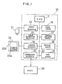
- the visual sensor system is provided with an image processing device 10 having a main central processing unit (hereinafter, referred to as a main CPU) 11.
- a camera interface 12, image processing processor 13, console interface 14, communication interface 15, frame memory 16, control software memory 17, program memory 18 and data memory 19 are connected to the main CPU 11 via a bus 20.
- a camera 21, mounted on an operating section (not shown) of a robot 30 so as to be moved together with the operating section, for instance, and a second camera, not shown, are connected to the cameral interface 12.
- a console 22 is connected to the console interface 14.
- a control section of a machine on which the visual sensor system is to be mounted for example, a control section (not shown) of the robot 30, is connected to the communication interface 15.
- the console 22 includes various keys 22a, including numeral keys, for selection of the operating modes of the visual sensor system, input of various instructions, and input, edition, registration and execution of programs.
- the console also includes a liquid crystal display unit 22b for displaying various operation menus, program lists and the like.
- the control software memory 17, formed of a ROM is arranged to store visual sensor system controlling programs
- the program memory 18, formed of a RAM is arranged to store a user program for setting nominal data and deriving correction data.
- the user program is created by an operator by operating the keys 22a of the console 22 in accordance with the menu displayed on the display unit 22b of the console 22. Routines respectively for nominal data setting and correction data deriving are provided in pairs in a predetermined portion of the program.
- a first correction data deriving routine 101a and a first nominal data setting routine 101b are provided in pairs in a first predetermined portion 101 of the user program lying between first and second instruction groups 100 and 102 of the user program.
- second correction data deriving routine 103a and a second nominal data setting routine 103b are provided in pairs in a second predetermined portion 103 lying between the second and third instruction groups 102 and 104.
- An example of the user program is shown below.
- the main CPU 11 of the image processing device 10 in the visual sensor system responds to the command, so that a flag memory (not shown) contained in the CPU stores flag information representing the selected operation mode of the visual sensor system.
- the main CPU 11 is operated in accordance with the sensor system controlling program stored in the control software memory 17.
- the CPU 11 executes the user program (Fig. 2) for the nominal data setting/correction data deriving, which is read out from the program memory 18.
- a snap command is read out from the first instruction group 100 of the program, a video signal supplied from the camera 21 is subjected to various processings which are known in the art, so that gray-scale image data, consisting of a predetermined number of picture elements each represented by a predetermined number of bits, are created, and then stored in the frame memory 16.
- the gray-scale image data is image-processed in the image processing processor 13 in a well known manner.
- a workpiece (not shown), which is an object to be processed by the robot 30 and photographed by the camera 21, is recognized, and data representing the position and posture (image parameter) of the workpiece in the sensor coordinate system is created.
- the main CPU 11 determines which one of the nominal mode and actual mode is selected on the basis of the flag information (step S200 in Fig. 3).
- the main CPU 11 executes the first nominal data setting routine 101b.
- the CPU causes the liquid crystal display unit 22b of the console 22 to display an interrogation message "Nominal data setting required ?" (step S201), and determines whether or not the operator operates a predetermined key of the console 22 so as to input the nominal data setting command in response to the message (step S202).
- the main CPU 11 subjects the workpiece position and posture data in the sensor coordinate system to the coordinate conversion process to obtain the workpiece position and posture data in the robot coordinate system, and causes the data memory 19 to store the same as nominal data (step S203).
- the operator is enabled to prevent either one of two nominal data from being set when he determines that it is not necessary to set a corresponding one of the two nominal data, for instance.
- the operating position and posture of the robot 30 obtained at the time of input of the nominal data setting command are instructed to the robot.
- the main CPU 11 executes the second instruction group 102 corresponding to the first instruction group 100.
- the main CPU 11 of the visual sensor system executes the user program of Fig. 2 in the same manner as in the above- described case.
- the main CPU 11 determines, on the basis of the flag information at the step S200, that the actual mode is selected, and executes the correction data deriving routine 101a.
- the main CPU 11 calculates, as incremental correction data, a difference between data representing the workpiece position and posture in the robot coordinate system obtained by the same proceedings as described above and the nominal data obtained in the preceding nominal mode.
- the incremental correction data is supplied to the control section of the robot via the communication interface 15.
- the robot control section controls the position and posture of the operating sections of the robot in a conventional manner while effecting the conventional correcting operation of the operating position/posture in accordance with the incremental correction data, to thereby perform required operations.
Abstract
Description
- The present invention relates to an automatic nominal data setting method and a correction data deriving method in a visual sensor system.
- In various machines such as industrial robots, it is conventionally known to correct the position and posture of operating sections of the machine in accordance with correction data supplied from a visual sensor system which is mounted on the machine. In operating the robot, for instance, the visual sensor system detects the operating position and posture of the robot, and supplies detection data to a control section of the robot. The control section determines correction data on the basis of the detection data and reference data (hereinafter, referred to as nominal data) such as data indicative of the operating position and posture of the robot which are set beforehand when teaching to the robot is effected, and corrects the operating position and posture of the robot. Conventionally, the nominal data for correction of operation is manually set beforehand by an operator. Therefore, the nominal data setting is troublesome and must be carried out by an skilled person.
- An object of the present invention is to provide an automatic nominal data setting method in a visual sensor system which makes it possible to accurately and rapidly set the nominal data with ease.
- Another object of the present invention is to provide a correction data deriving method in a visual sensor system which is executable on the basis of the automatically set nominal data.
- In order to achieve the above object, according to the present invention, the automatic nominal data setting method in a visual sensor comprises steps of: (a) operating the visual sensor system to execute a program provided at its predetermined portion with a predetermined routine for nominal data setting; (b) detecting a value of a predetermined image parameter associated with the nominal data; and automatically setting, as the nominal data, the predetermined image parameter value which is detected at the time of executing the predetermined routine.
- According to another aspect of the present invention, the correction data deriving method in the visual sensor system comprises steps of: (a) operating the visual sensor system to execute a program provided, in pairs, at its predetermined portion with first and second predetermined routines respectively for nominal data setting and correction data deriving; (b) detecting a value of a predetermined image parameter associated with the nominal data; (c) selecting one of a nominal mode where the program is executed with the first predetermined routine included and the second predetermined routine excluded and an actual mode where the program is executed with the first predetermined routine excluded and the second predetermined routine included; (d) automatically setting, as the nominal data, the predetermined image parameter value which is detected at the time of executing the first predetermined routine in the nominal mode; and (e) deriving correction data on the basis of the nominal data and the predetermined image parameter value which is detected at the time of executing the second predetermined routine in the actual mode.
- As described above, according to the present invention, since the value of the image parameter, associated with the nominal data, which is detected at the time of executing the predetermined routine provided in the predetermined portion of the program, is automatically set as the nominal data, the nominal data setting in the visual sensor system can be accurately and rapidly effected with ease. Further, since the data for correction of operation of various machines is derived on the basis of the automatically set nominal data, the operation correction can be effected in an appropriate manner.
-
- Fig. 1 is a block diagram showing an essential part of a visual sensor system for effecting the automatic nominal data setting method and correction data deriving method according to an embodiment of the present invention;
- Fig. 2 is a diagram showing, by way of example, a program executed by the visual sensor system of Fig. 1; and
- Fig. 3 is a diagram exemplarily showing a nominal data setting routine.
- A visual sensor system for embodying a method of an embodiment of the present invention is mounted on an industrial robot, for instance, and is arranged to supply robot operation correction data to the robot. To this end, the visual sensor system is so designed as to be operated in a nominal mode where nominal data (for example, reference data indicative of the position and posture of a specified part of a workpiece when teaching to the robot is performed) for correction data derivation is automatically detected to be stored, and in an actual mode where the correction data is derived to be supplied to the robot.
- Referring to Fig. 1, the visual sensor system is provided with an
image processing device 10 having a main central processing unit (hereinafter, referred to as a main CPU) 11. Acamera interface 12,image processing processor 13,console interface 14,communication interface 15,frame memory 16,control software memory 17,program memory 18 anddata memory 19 are connected to the main CPU 11 via abus 20. Acamera 21, mounted on an operating section (not shown) of arobot 30 so as to be moved together with the operating section, for instance, and a second camera, not shown, are connected to thecameral interface 12. Aconsole 22 is connected to theconsole interface 14. Further, a control section of a machine on which the visual sensor system is to be mounted, for example, a control section (not shown) of therobot 30, is connected to thecommunication interface 15. - More specifically, the
console 22 includesvarious keys 22a, including numeral keys, for selection of the operating modes of the visual sensor system, input of various instructions, and input, edition, registration and execution of programs. The console also includes a liquid crystal display unit 22b for displaying various operation menus, program lists and the like. Thecontrol software memory 17, formed of a ROM, is arranged to store visual sensor system controlling programs, and theprogram memory 18, formed of a RAM, is arranged to store a user program for setting nominal data and deriving correction data. The user program is created by an operator by operating thekeys 22a of theconsole 22 in accordance with the menu displayed on the display unit 22b of theconsole 22. Routines respectively for nominal data setting and correction data deriving are provided in pairs in a predetermined portion of the program. For example, as shown in Fig. 2, a first correctiondata deriving routine 101a and a first nominaldata setting routine 101b are provided in pairs in a firstpredetermined portion 101 of the user program lying between first andsecond instruction groups data deriving routine 103a and a second nominaldata setting routine 103b are provided in pairs in a secondpredetermined portion 103 lying between the second andthird instruction groups - SNAP
- CIRCLE FIND
- RECOG OBJECT
- CONV DATA
- SNAP
- CIRCLE FIND
- RECOG OBJECT
- CONV DATA
- SEND DATA
- In the following, the operation of the visual sensor system with the above construction will be now explained with reference to Fig. 3.
- When the operator operates a predetermined key of the
console 22 to input a nominal mode selection command or an actual mode selection command to the visual sensor system, the main CPU 11 of theimage processing device 10 in the visual sensor system responds to the command, so that a flag memory (not shown) contained in the CPU stores flag information representing the selected operation mode of the visual sensor system. - During the teaching operation for the
robot 30 effected by the operator or the actual operation of the robot performed in accordance with the teaching program stored in a memory section (not shown) of therobot 30, the main CPU 11 is operated in accordance with the sensor system controlling program stored in thecontrol software memory 17. In relation to the present invention, the CPU 11 executes the user program (Fig. 2) for the nominal data setting/correction data deriving, which is read out from theprogram memory 18. When a snap command is read out from thefirst instruction group 100 of the program, a video signal supplied from thecamera 21 is subjected to various processings which are known in the art, so that gray-scale image data, consisting of a predetermined number of picture elements each represented by a predetermined number of bits, are created, and then stored in theframe memory 16. Next, the gray-scale image data is image-processed in theimage processing processor 13 in a well known manner. As a result, a workpiece (not shown), which is an object to be processed by therobot 30 and photographed by thecamera 21, is recognized, and data representing the position and posture (image parameter) of the workpiece in the sensor coordinate system is created. - Next, the first
predetermined portion 101 of the user program is executed. At this time, the main CPU 11 determines which one of the nominal mode and actual mode is selected on the basis of the flag information (step S200 in Fig. 3). When the nominal mode is selected (in other words, during the teaching operation to the robot 30), the main CPU 11 executes the first nominaldata setting routine 101b. At first, the CPU causes the liquid crystal display unit 22b of theconsole 22 to display an interrogation message "Nominal data setting required ?" (step S201), and determines whether or not the operator operates a predetermined key of theconsole 22 so as to input the nominal data setting command in response to the message (step S202). When the command is input, the main CPU 11 subjects the workpiece position and posture data in the sensor coordinate system to the coordinate conversion process to obtain the workpiece position and posture data in the robot coordinate system, and causes thedata memory 19 to store the same as nominal data (step S203). As a result of the provision of the message display step S201, the setting command input determination step S202 and the nominal data setting step S203, the operator is enabled to prevent either one of two nominal data from being set when he determines that it is not necessary to set a corresponding one of the two nominal data, for instance. Meanwhile, the operating position and posture of therobot 30 obtained at the time of input of the nominal data setting command are instructed to the robot. Next, the main CPU 11 executes thesecond instruction group 102 corresponding to thefirst instruction group 100. That is, an image is derived from the second camera and subjected to the image processing to recognize the object. Then, the same processing as described above is effected with respect to the second predeterminedportion 103 following the second instruction group, and further executes thethird instruction group 104 so as to supply the first and second correction data to therobot 30, for instance. Thus, the operation of the visual sensor system in the nominal mode is completed. In the meantime, the operation in the nominal mode is completed when it is determined at the step S202 that the nominal data setting command is not input. - On the other hand, during the actual operation of the
robot 30, that is, during the operation in the actual mode of the visual sensor system, the main CPU 11 of the visual sensor system executes the user program of Fig. 2 in the same manner as in the above- described case. However, when the execution of the firstpredetermined portion 101 of the user program following thefirst instruction group 100 thereof is started, the main CPU 11 determines, on the basis of the flag information at the step S200, that the actual mode is selected, and executes the correction data deriving routine 101a. In the deriving routine 101a, the main CPU 11 calculates, as incremental correction data, a difference between data representing the workpiece position and posture in the robot coordinate system obtained by the same proceedings as described above and the nominal data obtained in the preceding nominal mode. Next, the incremental correction data is supplied to the control section of the robot via thecommunication interface 15. The robot control section controls the position and posture of the operating sections of the robot in a conventional manner while effecting the conventional correcting operation of the operating position/posture in accordance with the incremental correction data, to thereby perform required operations.
Claims (4)
Applications Claiming Priority (3)
| Application Number | Priority Date | Filing Date | Title |
|---|---|---|---|
| JP63162657A JPH0213804A (en) | 1988-07-01 | 1988-07-01 | Nominal setting system for vision sensor |
| JP162657/88 | 1988-07-01 | ||
| PCT/JP1989/000661 WO1990000109A1 (en) | 1988-07-01 | 1989-06-30 | Nominal data automatic setting method of visual sensor system |
Publications (3)
| Publication Number | Publication Date |
|---|---|
| EP0378703A1 true EP0378703A1 (en) | 1990-07-25 |
| EP0378703A4 EP0378703A4 (en) | 1992-07-22 |
| EP0378703B1 EP0378703B1 (en) | 1996-06-05 |
Family
ID=15758796
Family Applications (1)
| Application Number | Title | Priority Date | Filing Date |
|---|---|---|---|
| EP89907821A Expired - Lifetime EP0378703B1 (en) | 1988-07-01 | 1989-06-30 | Nominal data automatic setting method of visual sensor system |
Country Status (5)
| Country | Link |
|---|---|
| US (1) | US5066902A (en) |
| EP (1) | EP0378703B1 (en) |
| JP (1) | JPH0213804A (en) |
| DE (1) | DE68926614T2 (en) |
| WO (1) | WO1990000109A1 (en) |
Cited By (1)
| Publication number | Priority date | Publication date | Assignee | Title |
|---|---|---|---|---|
| EP0554464A1 (en) * | 1991-08-27 | 1993-08-11 | Fanuc Ltd. | Method of diagnosing real time sensor |
Families Citing this family (19)
| Publication number | Priority date | Publication date | Assignee | Title |
|---|---|---|---|---|
| JP2806604B2 (en) * | 1990-06-29 | 1998-09-30 | ファナック株式会社 | Camera displacement detection method |
| US6356671B1 (en) * | 1991-07-05 | 2002-03-12 | Fanuc Ltd. | Image processing method for an industrial visual sensor |
| US5255096B1 (en) * | 1992-04-10 | 1997-12-23 | William M Boyle | Video time code synchronized robot control apparatus |
| JP2769947B2 (en) * | 1992-05-15 | 1998-06-25 | 株式会社椿本チエイン | Manipulator position / posture control method |
| US5606494A (en) * | 1993-11-25 | 1997-02-25 | Casio Computer Co., Ltd. | Switching apparatus |
| JP3394322B2 (en) * | 1994-05-19 | 2003-04-07 | ファナック株式会社 | Coordinate system setting method using visual sensor |
| US5853330A (en) * | 1994-06-02 | 1998-12-29 | Engstrand; Brad | Sensory simulator and editor |
| US5496220A (en) * | 1994-06-02 | 1996-03-05 | Brad Engstrand | Sensory simulator |
| JP3418456B2 (en) * | 1994-06-23 | 2003-06-23 | ファナック株式会社 | Robot position teaching tool and robot position teaching method |
| JPH0970780A (en) * | 1995-09-06 | 1997-03-18 | Fanuc Ltd | Tool shape correcting method of robot |
| KR970062838A (en) * | 1996-02-27 | 1997-09-12 | 이종수 | Three-dimensional robot calibration device and method using CCD camera and laser |
| US6136653A (en) | 1998-05-11 | 2000-10-24 | Mosel Vitelic, Inc. | Method and device for producing undercut gate for flash memory |
| US6039653A (en) * | 1998-11-16 | 2000-03-21 | Engstrand; Brad | Apparatus, system and method for experiencing motion |
| DE10120948C1 (en) * | 2001-04-23 | 2002-11-28 | Schunk Gmbh & Co Kg | Sensor system for a gripper system and gripper system |
| US7870504B1 (en) * | 2003-10-01 | 2011-01-11 | TestPlant Inc. | Method for monitoring a graphical user interface on a second computer display from a first computer |
| JP5939267B2 (en) * | 2014-03-05 | 2016-06-22 | 株式会社安川電機 | Robot monitoring system, robot monitoring apparatus, robot monitoring method, robot monitoring module, and robot monitoring program |
| GB2547220A (en) | 2016-02-10 | 2017-08-16 | Testplant Europe Ltd | Method of, and apparatus for, testing computer hardware and software |
| GB2547222A (en) | 2016-02-10 | 2017-08-16 | Testplant Europe Ltd | Method of, and apparatus for, testing computer hardware and software |
| EP3946825A1 (en) * | 2019-03-25 | 2022-02-09 | ABB Schweiz AG | Method and control arrangement for determining a relation between a robot coordinate system and a movable apparatus coordinate system |
Citations (3)
| Publication number | Priority date | Publication date | Assignee | Title |
|---|---|---|---|---|
| US4704694A (en) * | 1985-12-16 | 1987-11-03 | Automation Intelligence, Inc. | Learned part system |
| US4707647A (en) * | 1986-05-19 | 1987-11-17 | Gmf Robotics Corporation | Gray scale vision method and system utilizing same |
| US4712970A (en) * | 1984-06-08 | 1987-12-15 | Hitachi, Ltd. | Method for handling a work in a robot system |
Family Cites Families (14)
| Publication number | Priority date | Publication date | Assignee | Title |
|---|---|---|---|---|
| JPS50112969A (en) * | 1974-02-18 | 1975-09-04 | ||
| JPS5916286B2 (en) * | 1976-03-24 | 1984-04-14 | 株式会社日立製作所 | Operation control method for industrial robots |
| JPS5856003A (en) * | 1981-09-30 | 1983-04-02 | Hitachi Ltd | Controlling method for industrial robot |
| JPS59189415A (en) * | 1983-04-13 | 1984-10-27 | Hitachi Ltd | Method and device for teaching motion of industrial robot |
| JPS6035209A (en) * | 1983-08-08 | 1985-02-23 | Amada Co Ltd | Automatic measuring method using measuring robot |
| JPS60196604A (en) * | 1984-03-19 | 1985-10-05 | Tokico Ltd | Industrial robot |
| JPS61130809A (en) * | 1984-11-30 | 1986-06-18 | Mitsubishi Electric Corp | Visual sensor |
| JPH0619335B2 (en) * | 1985-01-25 | 1994-03-16 | シグマツクス株式会社 | Object recognition device |
| JPS61173878A (en) * | 1985-01-30 | 1986-08-05 | 株式会社日立製作所 | Individual-difference corresponding teach data correction system of robot |
| JPS61279480A (en) * | 1985-06-04 | 1986-12-10 | 株式会社不二越 | Method of teaching operation point of robot |
| JPS62145104A (en) * | 1985-12-19 | 1987-06-29 | Fanuc Ltd | Controlling method for vision system |
| US4757459A (en) * | 1986-05-29 | 1988-07-12 | Cincinnati Milacron Inc. | Apparatus and method for programming a computer operated robot arm using macro instructions |
| JP3104000B2 (en) * | 1993-01-11 | 2000-10-30 | 新日本製鐵株式会社 | Light reduction method in continuous casting |
| JP2621756B2 (en) * | 1993-04-05 | 1997-06-18 | 日本電気株式会社 | Video switcher self-diagnosis device |
-
1988
- 1988-07-01 JP JP63162657A patent/JPH0213804A/en active Pending
-
1989
- 1989-06-30 EP EP89907821A patent/EP0378703B1/en not_active Expired - Lifetime
- 1989-06-30 DE DE68926614T patent/DE68926614T2/en not_active Expired - Fee Related
- 1989-06-30 WO PCT/JP1989/000661 patent/WO1990000109A1/en active IP Right Grant
- 1989-06-30 US US07/465,108 patent/US5066902A/en not_active Expired - Lifetime
Patent Citations (3)
| Publication number | Priority date | Publication date | Assignee | Title |
|---|---|---|---|---|
| US4712970A (en) * | 1984-06-08 | 1987-12-15 | Hitachi, Ltd. | Method for handling a work in a robot system |
| US4704694A (en) * | 1985-12-16 | 1987-11-03 | Automation Intelligence, Inc. | Learned part system |
| US4707647A (en) * | 1986-05-19 | 1987-11-17 | Gmf Robotics Corporation | Gray scale vision method and system utilizing same |
Non-Patent Citations (1)
| Title |
|---|
| See also references of WO9000109A1 * |
Cited By (3)
| Publication number | Priority date | Publication date | Assignee | Title |
|---|---|---|---|---|
| EP0554464A1 (en) * | 1991-08-27 | 1993-08-11 | Fanuc Ltd. | Method of diagnosing real time sensor |
| EP0554464A4 (en) * | 1991-08-27 | 1994-02-16 | Fanuc Ltd. | |
| US5511007A (en) * | 1991-08-27 | 1996-04-23 | Fanuc Ltd. | Diagnostic method for a real time sensor mounted on a robot |
Also Published As
| Publication number | Publication date |
|---|---|
| EP0378703A4 (en) | 1992-07-22 |
| EP0378703B1 (en) | 1996-06-05 |
| JPH0213804A (en) | 1990-01-18 |
| DE68926614D1 (en) | 1996-07-11 |
| DE68926614T2 (en) | 1996-10-02 |
| WO1990000109A1 (en) | 1990-01-11 |
| US5066902A (en) | 1991-11-19 |
Similar Documents
| Publication | Publication Date | Title |
|---|---|---|
| EP0378703B1 (en) | Nominal data automatic setting method of visual sensor system | |
| EP0549805B1 (en) | Automatic calibration method | |
| US6236896B1 (en) | Coordinate system setting method using visual sensor | |
| US10656618B2 (en) | Numerical controller | |
| US7151848B1 (en) | Image processing apparatus for robot | |
| US7742839B2 (en) | Robot system provided with robot controller | |
| EP0278421A1 (en) | Instruction system of remote-control robot | |
| EP0494308A1 (en) | Method of detecting shift in camera position | |
| US4845346A (en) | Touch panel having parallax compensation and intermediate coordinate determination | |
| EP0529077B1 (en) | Method of teaching robot | |
| JPH06250730A (en) | Teaching device for industrial robot | |
| JP3196309B2 (en) | Industrial robot | |
| EP0708392A1 (en) | Operational guidance system for measuring machine | |
| JPH0535323A (en) | Nc device | |
| JP2686158B2 (en) | Numerical control device having data calculation input function | |
| JPH0413530A (en) | Instructing method for industrial assembled robot | |
| JPH06315882A (en) | Weight/center of gravity position correcting device for force control working machine | |
| EP0477366B1 (en) | Method of setting teaching data in a visual sensor system | |
| JPH11351824A (en) | Coordinate system correcting method and image measuring instrument | |
| JP2824647B2 (en) | Vision sensor | |
| JPH0821081B2 (en) | Window control method | |
| WO2023053368A1 (en) | Teaching device and robot system | |
| WO2022249249A9 (en) | Video analysis device, video analysis system, and storage medium | |
| JPH05301195A (en) | Camera position slippage detecting method in visual sensor | |
| JP2950544B2 (en) | Image processing method in visual sensor system |
Legal Events
| Date | Code | Title | Description |
|---|---|---|---|
| PUAI | Public reference made under article 153(3) epc to a published international application that has entered the european phase |
Free format text: ORIGINAL CODE: 0009012 |
|
| 17P | Request for examination filed |
Effective date: 19900228 |
|
| AK | Designated contracting states |
Kind code of ref document: A1 Designated state(s): DE FR GB |
|
| A4 | Supplementary search report drawn up and despatched |
Effective date: 19920605 |
|
| AK | Designated contracting states |
Kind code of ref document: A4 Designated state(s): DE FR GB |
|
| 17Q | First examination report despatched |
Effective date: 19950214 |
|
| GRAH | Despatch of communication of intention to grant a patent |
Free format text: ORIGINAL CODE: EPIDOS IGRA |
|
| GRAH | Despatch of communication of intention to grant a patent |
Free format text: ORIGINAL CODE: EPIDOS IGRA |
|
| GRAA | (expected) grant |
Free format text: ORIGINAL CODE: 0009210 |
|
| AK | Designated contracting states |
Kind code of ref document: B1 Designated state(s): DE FR GB |
|
| PG25 | Lapsed in a contracting state [announced via postgrant information from national office to epo] |
Ref country code: FR Effective date: 19960605 |
|
| REF | Corresponds to: |
Ref document number: 68926614 Country of ref document: DE Date of ref document: 19960711 |
|
| PG25 | Lapsed in a contracting state [announced via postgrant information from national office to epo] |
Ref country code: GB Effective date: 19960905 |
|
| EN | Fr: translation not filed | ||
| PLBE | No opposition filed within time limit |
Free format text: ORIGINAL CODE: 0009261 |
|
| STAA | Information on the status of an ep patent application or granted ep patent |
Free format text: STATUS: NO OPPOSITION FILED WITHIN TIME LIMIT |
|
| GBPC | Gb: european patent ceased through non-payment of renewal fee |
Effective date: 19960905 |
|
| 26N | No opposition filed | ||
| PGFP | Annual fee paid to national office [announced via postgrant information from national office to epo] |
Ref country code: DE Payment date: 20070606 Year of fee payment: 19 |
|
| PG25 | Lapsed in a contracting state [announced via postgrant information from national office to epo] |
Ref country code: DE Free format text: LAPSE BECAUSE OF NON-PAYMENT OF DUE FEES Effective date: 20090101 |