EP0371752A1 - Tracheostomy tube assemblies - Google Patents
Tracheostomy tube assemblies Download PDFInfo
- Publication number
- EP0371752A1 EP0371752A1 EP89312343A EP89312343A EP0371752A1 EP 0371752 A1 EP0371752 A1 EP 0371752A1 EP 89312343 A EP89312343 A EP 89312343A EP 89312343 A EP89312343 A EP 89312343A EP 0371752 A1 EP0371752 A1 EP 0371752A1
- Authority
- EP
- European Patent Office
- Prior art keywords
- tube
- obturator
- nose portion
- tracheostomy tube
- assembly according
- Prior art date
- Legal status (The legal status is an assumption and is not a legal conclusion. Google has not performed a legal analysis and makes no representation as to the accuracy of the status listed.)
- Withdrawn
Links
Images
Classifications
-
- A—HUMAN NECESSITIES
- A61—MEDICAL OR VETERINARY SCIENCE; HYGIENE
- A61M—DEVICES FOR INTRODUCING MEDIA INTO, OR ONTO, THE BODY; DEVICES FOR TRANSDUCING BODY MEDIA OR FOR TAKING MEDIA FROM THE BODY; DEVICES FOR PRODUCING OR ENDING SLEEP OR STUPOR
- A61M16/00—Devices for influencing the respiratory system of patients by gas treatment, e.g. mouth-to-mouth respiration; Tracheal tubes
- A61M16/04—Tracheal tubes
- A61M16/0465—Tracheostomy tubes; Devices for performing a tracheostomy; Accessories therefor, e.g. masks, filters
-
- A—HUMAN NECESSITIES
- A61—MEDICAL OR VETERINARY SCIENCE; HYGIENE
- A61M—DEVICES FOR INTRODUCING MEDIA INTO, OR ONTO, THE BODY; DEVICES FOR TRANSDUCING BODY MEDIA OR FOR TAKING MEDIA FROM THE BODY; DEVICES FOR PRODUCING OR ENDING SLEEP OR STUPOR
- A61M16/00—Devices for influencing the respiratory system of patients by gas treatment, e.g. mouth-to-mouth respiration; Tracheal tubes
- A61M16/04—Tracheal tubes
- A61M16/0402—Special features for tracheal tubes not otherwise provided for
- A61M16/0429—Special features for tracheal tubes not otherwise provided for with non-integrated distal obturators
-
- A—HUMAN NECESSITIES
- A61—MEDICAL OR VETERINARY SCIENCE; HYGIENE
- A61M—DEVICES FOR INTRODUCING MEDIA INTO, OR ONTO, THE BODY; DEVICES FOR TRANSDUCING BODY MEDIA OR FOR TAKING MEDIA FROM THE BODY; DEVICES FOR PRODUCING OR ENDING SLEEP OR STUPOR
- A61M16/00—Devices for influencing the respiratory system of patients by gas treatment, e.g. mouth-to-mouth respiration; Tracheal tubes
- A61M16/04—Tracheal tubes
- A61M16/0434—Cuffs
Definitions
- This invention relates to tracheostomy tube assemblies of the kind comprising a tracheostomy tube with a patient end adapted for location within the trachea of a patient and a machine end adapted to extend through a surgically made opening into the trachea and to be located externally of the trachea, and an obturator for use in insertion of the tracheostomy tube.
- Tracheostomy tubes are used to provide an airway or gas ventilation path directly to the patient's trachea through a surgically made opening in the throat.
- the opening into the trachea is preferably made just large enough to accommodate the tube. This can make insertion of the tube through the opening difficult, since it must be pushed through resilient cartilage.
- Obturators can be used to provide the tube with additional stiffness and to prevent entry of tissue into the patient end of the tube. Such obturators do not significantly help insertion since they only project from the patient end by a maximum distance about equal to the internal diameter of the tube.
- a tracheostomy tube assembly of the above-specified kind, characterised in that the obturator extends along the tracheostomy tube and projects from the patient end thereof, that the obturator includes a flexible stem and a nose portion at the patient end of the obturator, the nose portion being of a soft resilient material, and tapering to its tip, that the nose portion is arranged to project out of the patient end of the tube by a distance at least twice the internal diameter of the tube at its patient end such that the nose portion forms a lead for introduction of the assembly into the trachea, and that the stem and the nose portion are more flexible than the tube such that the obturator means can be withdrawn from the tube after insertion by pulling the machine end of the obturator without any substantial bending of the tube.
- the nose portion preferably projects from the patient end of the tube by a distance approximately two and a half times the internal diameter of the tube at its patient end.
- the nose portion is preferably curved along its length and may have a Shore hardness of approximately 83.
- the nose portion may be of silicone rubber and may be of substantially circular section.
- the stem is preferably of a material different from that of the nose portion and may be cruciform in section along a major part of its length.
- the patient end of the obturator may be treated to be of low friction.
- the machine end of the obturator and the tube both have respective means which are aligned with one another to ensure correct orientation of the obturator in the tube.
- a tracheostomy tube assembly including an obturator, and a method of inserting a tracheostomy tube, in accordance with the present invention will now be described, by way of example, with reference to the accompanying drawings, in which:
- the tracheostomy tube assembly comprises a conventional tracheostomy tube 1 and a novel obturator 2 used for introducing the tube into the patient's trachea.
- the tracheostomy tube 1 is of a semi-flexible plastics material such as PVC, having a patient end 10 that is, in use, located in the trachea 3.
- the patient end of the tube is straight and carries an inflatable cuff 11 that encircles it and which forms a seal with the trachea when inflated.
- the machine end 12 of the tube is also straight and extends at right angles to the patient end 10, being joined with it by an integral intermediate curved region 13.
- the machine end 12 extends through a surgically cut opening or stoma 4 and is located outside the trachea, close to the patient's neck, being terminated by a luer taper male coupling 14.
- a flange 15 is also mounted on the tube to serve in stabilizing the tube at the stoma.
- An inflation line 16 communicates with the interior of the cuff 11 via a bore (not shown) along the tube 1 within its wall.
- the inflation line 16 is joined to the bore close to the machine end 12 and includes an inflation indicator 17 and coupling 18 of the usual kind.
- the obturator 2 has, at its patient end, a nose portion 20 of a soft, resilient, elastomeric material such as silicone rubber. Typically the hardness of the nose portion is about 83 Shore hardness.
- the nose portion 20 is of circular section and tapers along its length to a rounded tip 21.
- the length of the obturator 2 is such that the nose portion 20 projects from the patient end 10 of the tube 1 by a distance that is at least twice the internal diameter of the patient end of the tube and is preferably two and half times the diameter.
- the nose portion 20 is curved along its length slightly to the right in the drawings, that is, towards the front surface of the patient's neck, and in the same plane and sense as the bend in the tube 1.
- the diameter of the nose portion 20 where it emerges from the patient end of the tube is the same as the internal diameter of the tube so that it is a sliding fit in the tube and seals its patient end.
- the nose portion 20 is securely attached to the patient end of a stem portion 22 which is of a semi-flexible plastics material, such as nylon.
- the stem portion 22 is of cruciform section along a major part of its length, and tapers, along its length, being smaller at its patient end.
- the stem portion is formed with a radially-extending stop 23 of disc shape. A projection 24 from the edge of the stop 23 serves to identify the orientation of the obturator.
- the cruciform section of the obturator gives it sufficient axial rigidity to enable it to be inserted into the tube against the action of friction between the nose portion 20 and the tube wall.
- the friction can be reduced by lubricating the forward end of the obturator or otherwise treating it to be of low friction such as by a suitable coating.
- the dimensions and material of the stem 22 ensure that it is relatively flexible transversely, that is, more flexible than the tube 1.
- the obturator 2 In use, the obturator 2 is pushed into the tube 1 as far as possible, the extent of insertion being limited by engagement of the stop 23 with the coupling 14.
- the projection 24 is aligned with a marking, or a cooperating recess (not shown), on the tube 1 to ensure that the nose portion 20 bends in the desired direction.
- a lock may also be provided to hold the obturator in position.
- the tip 21 of the nose portion is pushed into the surgically made stoma 4, in the manner shown in Figure 4.
- the length of the obturator 2 projecting from the tube 1 ensures that the region of the stoma 4 can be clearly seen by the surgeon and is not obstructed by the tube during the initial part of the insertion.
- the stoma is opened progressively by the tapering tip 21 of the obturator 2 which guides the assembly through the stoma.
- the surgeon bends the assembly downwards to follow the lead of the obturator tip.
- the tip 21 of the obturator 2 may contact the rear surface of the wall of the trachea.
- the soft nature of the nose portion 20, however, ensures that this causes little risk of trauma, and the bend of the obturator ensures that the patient end of the assembly is guided downwardly into its correct position shown in Figure 1.
- the obturator 20 When the assembly has been correctly positioned, with the flange 15 close to the patient's neck, the obturator 20 is quickly removed by pulling the stop 23 rearwardly.
- the flexible nature of the stem portion 22 and nose portion 20 ensures that the obturator can bend to follow the changes of curvature of the tube 1 along its length without causing any substantial bending of the tube.
- the cuff 11 can be inflated to seal the tube with the trachea 3.
- the obturator 20 has been found greatly to assist correct intubation and to reduce the discomfort to the patient.
- the obturator can be used with tubes of different sizes as commonly used for patients of different builds.
- the obturator can be of different shapes and materials whilst still being within the scope of the present invention.
Abstract
A tracheostomy tube obturator (2) has a nose (20) of silicone rubber which projects from the patient end (10) by a distance about two and a half times the internal diameter of the trachestomy tube (1). The nose (20) is circular in section, tapering to its tip (21), and is bent along its length, in the same plane and sense as the tube (1) so as to aid introduction of the tube into a stoma (4). The stem (22) of the obturator (2) is flexible and cruciform in section and is of a different material from that of he nose (20). At its machine end, the obturator (2) has a flange (23) with a projection (24) on one side which is aligned with a marking or recess on the machine end of the tube (1) so as to ensure correct orientation of the obturator in the tube.
Description
- This invention relates to tracheostomy tube assemblies of the kind comprising a tracheostomy tube with a patient end adapted for location within the trachea of a patient and a machine end adapted to extend through a surgically made opening into the trachea and to be located externally of the trachea, and an obturator for use in insertion of the tracheostomy tube.
- Tracheostomy tubes are used to provide an airway or gas ventilation path directly to the patient's trachea through a surgically made opening in the throat. In order to cause minimal trauma to the patient, the opening into the trachea is preferably made just large enough to accommodate the tube. This can make insertion of the tube through the opening difficult, since it must be pushed through resilient cartilage. Obturators can be used to provide the tube with additional stiffness and to prevent entry of tissue into the patient end of the tube. Such obturators do not significantly help insertion since they only project from the patient end by a maximum distance about equal to the internal diameter of the tube.
- It is an object of the present invention to provide an improved tracheostomy tube assembly.
- According to the present invention there is provided a tracheostomy tube assembly of the above-specified kind, characterised in that the obturator extends along the tracheostomy tube and projects from the patient end thereof, that the obturator includes a flexible stem and a nose portion at the patient end of the obturator, the nose portion being of a soft resilient material, and tapering to its tip, that the nose portion is arranged to project out of the patient end of the tube by a distance at least twice the internal diameter of the tube at its patient end such that the nose portion forms a lead for introduction of the assembly into the trachea, and that the stem and the nose portion are more flexible than the tube such that the obturator means can be withdrawn from the tube after insertion by pulling the machine end of the obturator without any substantial bending of the tube.
- The nose portion preferably projects from the patient end of the tube by a distance approximately two and a half times the internal diameter of the tube at its patient end. The nose portion is preferably curved along its length and may have a Shore hardness of approximately 83. The nose portion may be of silicone rubber and may be of substantially circular section. The stem is preferably of a material different from that of the nose portion and may be cruciform in section along a major part of its length. The patient end of the obturator may be treated to be of low friction. Preferably, the machine end of the obturator and the tube both have respective means which are aligned with one another to ensure correct orientation of the obturator in the tube.
- A tracheostomy tube assembly including an obturator, and a method of inserting a tracheostomy tube, in accordance with the present invention, will now be described, by way of example, with reference to the accompanying drawings, in which:
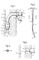
- Figure 1 is a side elevation showing the assembly inserted in a trachea;
- Figure 2 is a side elevation view of the obturator;
- Figure 3 is an enlarged transverse section of the obturator along line III-III; and
- Figure 4 is a side elevation showing a step in the insertion of the assembly.
- The tracheostomy tube assembly comprises a conventional tracheostomy tube 1 and a
novel obturator 2 used for introducing the tube into the patient's trachea. - The tracheostomy tube 1 is of a semi-flexible plastics material such as PVC, having a
patient end 10 that is, in use, located in the trachea 3. The patient end of the tube is straight and carries aninflatable cuff 11 that encircles it and which forms a seal with the trachea when inflated. - The machine end 12 of the tube is also straight and extends at right angles to the
patient end 10, being joined with it by an integral intermediatecurved region 13. Themachine end 12 extends through a surgically cut opening orstoma 4 and is located outside the trachea, close to the patient's neck, being terminated by a luer tapermale coupling 14. Aflange 15 is also mounted on the tube to serve in stabilizing the tube at the stoma. Aninflation line 16 communicates with the interior of thecuff 11 via a bore (not shown) along the tube 1 within its wall. Theinflation line 16 is joined to the bore close to themachine end 12 and includes aninflation indicator 17 andcoupling 18 of the usual kind. - With reference now to Figures 2 and 3, the
obturator 2 has, at its patient end, anose portion 20 of a soft, resilient, elastomeric material such as silicone rubber. Typically the hardness of the nose portion is about 83 Shore hardness. Thenose portion 20 is of circular section and tapers along its length to arounded tip 21. The length of theobturator 2 is such that thenose portion 20 projects from thepatient end 10 of the tube 1 by a distance that is at least twice the internal diameter of the patient end of the tube and is preferably two and half times the diameter. Thenose portion 20 is curved along its length slightly to the right in the drawings, that is, towards the front surface of the patient's neck, and in the same plane and sense as the bend in the tube 1. The diameter of thenose portion 20 where it emerges from the patient end of the tube is the same as the internal diameter of the tube so that it is a sliding fit in the tube and seals its patient end. Thenose portion 20 is securely attached to the patient end of astem portion 22 which is of a semi-flexible plastics material, such as nylon. Thestem portion 22 is of cruciform section along a major part of its length, and tapers, along its length, being smaller at its patient end. At its machine end, the stem portion is formed with a radially-extendingstop 23 of disc shape. Aprojection 24 from the edge of thestop 23 serves to identify the orientation of the obturator. The cruciform section of the obturator gives it sufficient axial rigidity to enable it to be inserted into the tube against the action of friction between thenose portion 20 and the tube wall. The friction can be reduced by lubricating the forward end of the obturator or otherwise treating it to be of low friction such as by a suitable coating. The dimensions and material of thestem 22 ensure that it is relatively flexible transversely, that is, more flexible than the tube 1. - In use, the
obturator 2 is pushed into the tube 1 as far as possible, the extent of insertion being limited by engagement of thestop 23 with thecoupling 14. Theprojection 24 is aligned with a marking, or a cooperating recess (not shown), on the tube 1 to ensure that thenose portion 20 bends in the desired direction. A lock may also be provided to hold the obturator in position. - With the assembly completed, the
tip 21 of the nose portion is pushed into the surgically madestoma 4, in the manner shown in Figure 4. The length of theobturator 2 projecting from the tube 1 ensures that the region of thestoma 4 can be clearly seen by the surgeon and is not obstructed by the tube during the initial part of the insertion. As the assembly is pushed into thestoma 4, the stoma is opened progressively by thetapering tip 21 of theobturator 2 which guides the assembly through the stoma. As the assembly enters the trachea 3, the surgeon bends the assembly downwards to follow the lead of the obturator tip. If the assembly is pushed too far to the rear before being bent down, thetip 21 of theobturator 2 may contact the rear surface of the wall of the trachea. The soft nature of thenose portion 20, however, ensures that this causes little risk of trauma, and the bend of the obturator ensures that the patient end of the assembly is guided downwardly into its correct position shown in Figure 1. - When the assembly has been correctly positioned, with the
flange 15 close to the patient's neck, theobturator 20 is quickly removed by pulling thestop 23 rearwardly. The flexible nature of thestem portion 22 andnose portion 20 ensures that the obturator can bend to follow the changes of curvature of the tube 1 along its length without causing any substantial bending of the tube. - Once the obturator has been removed, the
cuff 11 can be inflated to seal the tube with the trachea 3. - The
obturator 20 has been found greatly to assist correct intubation and to reduce the discomfort to the patient. - It will be appreciated that the obturator can be used with tubes of different sizes as commonly used for patients of different builds. The obturator can be of different shapes and materials whilst still being within the scope of the present invention.
Claims (10)
1. A tracheostomy tube assembly comprising a tracheostomy tube with a patient end adapted for location within the trachea of a patient and a machine end adapted to extend through a surgically made opening into the trachea and to be located externally of the trachea, and an obturator for use in insertion of the tracheostomy tube, characterised in that the obturator (2) extends along the tracheostomy tube (1) and projects from the patient end (10) thereof, that the obturator includes a flexible stem (22) and a nose portion (20) at the patient end of the obturator, the nose portion (20) being of a soft resilient material and tapering to its tip (21), that the nose portion (20) projects out of the patient end (10) of the tube (1) by a distance at least twice the internal diameter of the tube at its patient end such that the nose portion (20) forms a lead for introduction of the assembly into the trachea (3), and that the stem (22) and the nose portion (20) are more flexible than the tube such that the obturator can be withdrawn from the tube (11) after insertion by pulling the machine end of the obturator without any substantial bending of the tube.
2. A tracheostomy tube assembly according to Claim 1, characterised in that the nose portion (20) projects from the patient end (10) of the tube (1) by a distance approximately two and a half times the internal diameter of the tube (1) at its patient end (10).
3. A tracheostomy tube assembly according to Claim 1 or 2, characterised in that the nose portion (20) is curved along its length.
4. A tracheostomy tube assembly according to any one of the preceding claims, characterised in that the nose portion (20) has a Shore hardness of approximately 83.
5. A tracheostomy tube assembly according to any one of the preceding claims, characterised in that the nose portion (20) is substantially of a silicone rubber.
6. A tracheostomy tube assembly according to any one of the preceding claims, characterised in that nose portion (20) is of a substantially circular section.
7. A tracheostomy tube assembly according to any one of the preceding claims, characterised in that the stem (22) is of a material different from that of the nose portion (20).
8. A tracheostomy tube assembly according to any one of the preceding claims, characterised in that the stem (22) is cruciform in section along a major part of its length.
9. A tracheostomy tube assembly according to any one of the preceding claims, characterised in that the patient end of the obturator (2) is treated to be of low friction.
10. A tracheostomy tube assembly according to any one of the preceding claims, characterised in that the machine end of the obturator (2) and tube (1) both have respective means (24) which are aligned with one another to ensure correct orientation of the obturator (2) in the tube (1).
Applications Claiming Priority (2)
| Application Number | Priority Date | Filing Date | Title |
|---|---|---|---|
| GB8828012 | 1988-12-01 | ||
| GB8828012A GB8828012D0 (en) | 1988-12-01 | 1988-12-01 | Tracheostomy tube assembly & use |
Publications (1)
| Publication Number | Publication Date |
|---|---|
| EP0371752A1 true EP0371752A1 (en) | 1990-06-06 |
Family
ID=10647757
Family Applications (1)
| Application Number | Title | Priority Date | Filing Date |
|---|---|---|---|
| EP89312343A Withdrawn EP0371752A1 (en) | 1988-12-01 | 1989-11-28 | Tracheostomy tube assemblies |
Country Status (2)
| Country | Link |
|---|---|
| EP (1) | EP0371752A1 (en) |
| GB (1) | GB8828012D0 (en) |
Cited By (10)
| Publication number | Priority date | Publication date | Assignee | Title |
|---|---|---|---|---|
| US5287852A (en) * | 1993-01-13 | 1994-02-22 | Direct Trends International Ltd. | Apparatus and method for maintaining a tracheal stoma |
| EP0768096A2 (en) * | 1995-10-12 | 1997-04-16 | Smiths Industries Public Limited Company | Tracheostomy tubes and assemblies |
| JP2000308683A (en) * | 1999-04-12 | 2000-11-07 | Smiths Ind Plc | Obstructor and tube assembly |
| EP1281414A1 (en) * | 2001-08-04 | 2003-02-05 | Smiths Group PLC | Introducers and assemblies |
| WO2004069316A2 (en) * | 2003-02-03 | 2004-08-19 | Cook Critical Care | Tracheostomy tube dilator |
| EP1923090A3 (en) * | 2003-05-06 | 2008-08-13 | Mallinckrodt Inc. | Improved multiple cannula systems and methods |
| US8307824B2 (en) | 2008-06-27 | 2012-11-13 | Kimberly-Clark Worldwide, Inc. | Method of performing a tracheostomy |
| US8313687B2 (en) | 2007-09-20 | 2012-11-20 | Kimberly-Clark Worldwide, Inc. | Method of making an improved balloon cuff tracheostomy tube |
| US8607795B2 (en) | 2007-09-20 | 2013-12-17 | Kimberly-Clark Worldwide, Inc. | Balloon cuff tracheostomy tube |
| WO2016207583A1 (en) | 2015-06-24 | 2016-12-29 | Smiths Medical International Limited | Tube introducers. assemblies and methods |
Citations (8)
| Publication number | Priority date | Publication date | Assignee | Title |
|---|---|---|---|---|
| US1920006A (en) * | 1932-07-26 | 1933-07-25 | Edward A Arnim Jr | Prostatic catheter |
| US3606669A (en) * | 1969-05-26 | 1971-09-21 | Philip Morris Inc | Method of making tracheal tube device |
| FR2247262A2 (en) * | 1972-11-02 | 1975-05-09 | Technological Supply | Catheter tube for long-term intravenous therapy - silicone elastomer tube has non-binding supporting mandrel |
| US4246897A (en) * | 1979-02-15 | 1981-01-27 | Rudolph Muto | Tracheotomy obturator and tube flange |
| US4502482A (en) * | 1983-05-23 | 1985-03-05 | Deluccia Victor C | Endotracheal tube complex |
| DE3530310A1 (en) * | 1984-08-29 | 1986-03-13 | Sterimed Gesellschaft für medizinischen Bedarf mbH, 6600 Saarbrücken | Guide wire for catheters for blood vessels |
| US4637388A (en) * | 1984-10-15 | 1987-01-20 | Portex, Inc. | Tracheal tube obturator with reversible tip |
| EP0214063A1 (en) * | 1985-07-08 | 1987-03-11 | Bazenet, Jean Pierre | Intracorporal probe and device for mounting balloons on the same |
-
1988
- 1988-12-01 GB GB8828012A patent/GB8828012D0/en active Pending
-
1989
- 1989-11-28 EP EP89312343A patent/EP0371752A1/en not_active Withdrawn
Patent Citations (8)
| Publication number | Priority date | Publication date | Assignee | Title |
|---|---|---|---|---|
| US1920006A (en) * | 1932-07-26 | 1933-07-25 | Edward A Arnim Jr | Prostatic catheter |
| US3606669A (en) * | 1969-05-26 | 1971-09-21 | Philip Morris Inc | Method of making tracheal tube device |
| FR2247262A2 (en) * | 1972-11-02 | 1975-05-09 | Technological Supply | Catheter tube for long-term intravenous therapy - silicone elastomer tube has non-binding supporting mandrel |
| US4246897A (en) * | 1979-02-15 | 1981-01-27 | Rudolph Muto | Tracheotomy obturator and tube flange |
| US4502482A (en) * | 1983-05-23 | 1985-03-05 | Deluccia Victor C | Endotracheal tube complex |
| DE3530310A1 (en) * | 1984-08-29 | 1986-03-13 | Sterimed Gesellschaft für medizinischen Bedarf mbH, 6600 Saarbrücken | Guide wire for catheters for blood vessels |
| US4637388A (en) * | 1984-10-15 | 1987-01-20 | Portex, Inc. | Tracheal tube obturator with reversible tip |
| EP0214063A1 (en) * | 1985-07-08 | 1987-03-11 | Bazenet, Jean Pierre | Intracorporal probe and device for mounting balloons on the same |
Cited By (22)
| Publication number | Priority date | Publication date | Assignee | Title |
|---|---|---|---|---|
| US5287852A (en) * | 1993-01-13 | 1994-02-22 | Direct Trends International Ltd. | Apparatus and method for maintaining a tracheal stoma |
| EP0768096A2 (en) * | 1995-10-12 | 1997-04-16 | Smiths Industries Public Limited Company | Tracheostomy tubes and assemblies |
| EP0768096A3 (en) * | 1995-10-12 | 1997-08-13 | Smiths Industries Plc | Tracheostomy tubes and assemblies |
| US5983895A (en) * | 1995-10-12 | 1999-11-16 | Smiths Industries Plc | Tracheostomy tubes and assemblies |
| AU765068B2 (en) * | 1999-04-12 | 2003-09-11 | Smiths Group Plc | Obturators and tube asemblies |
| EP1044701A3 (en) * | 1999-04-12 | 2001-07-11 | Smiths Industries Public Limited Company | Obturators and tube assemblies |
| US6481436B1 (en) | 1999-04-12 | 2002-11-19 | Smiths Industries Public Limited Company | Obturators and tube assemblies |
| JP2000308683A (en) * | 1999-04-12 | 2000-11-07 | Smiths Ind Plc | Obstructor and tube assembly |
| EP1281414A1 (en) * | 2001-08-04 | 2003-02-05 | Smiths Group PLC | Introducers and assemblies |
| JP2003052827A (en) * | 2001-08-04 | 2003-02-25 | Smiths Group Plc | Insert tool for medical tube |
| GB2379393A (en) * | 2001-08-04 | 2003-03-12 | Smiths Group Plc | Tracheostomy tube obdurator |
| WO2004069316A2 (en) * | 2003-02-03 | 2004-08-19 | Cook Critical Care | Tracheostomy tube dilator |
| WO2004069316A3 (en) * | 2003-02-03 | 2005-03-31 | Cook Critical Care | Tracheostomy tube dilator |
| EP1923090A3 (en) * | 2003-05-06 | 2008-08-13 | Mallinckrodt Inc. | Improved multiple cannula systems and methods |
| US7681576B2 (en) | 2003-05-06 | 2010-03-23 | Mallinckrodt Inc. | Multiple cannula systems and methods |
| EP2322239A1 (en) * | 2003-05-06 | 2011-05-18 | Mallinckrodt Inc. | Improved multiple cannula systems and methods |
| US8151798B2 (en) | 2003-05-06 | 2012-04-10 | Tyco Healthcare Group Lp | Multiple cannula systems and methods |
| US8844535B2 (en) | 2003-05-06 | 2014-09-30 | Covidien Lp | Multiple cannula systems and methods |
| US8313687B2 (en) | 2007-09-20 | 2012-11-20 | Kimberly-Clark Worldwide, Inc. | Method of making an improved balloon cuff tracheostomy tube |
| US8607795B2 (en) | 2007-09-20 | 2013-12-17 | Kimberly-Clark Worldwide, Inc. | Balloon cuff tracheostomy tube |
| US8307824B2 (en) | 2008-06-27 | 2012-11-13 | Kimberly-Clark Worldwide, Inc. | Method of performing a tracheostomy |
| WO2016207583A1 (en) | 2015-06-24 | 2016-12-29 | Smiths Medical International Limited | Tube introducers. assemblies and methods |
Also Published As
| Publication number | Publication date |
|---|---|
| GB8828012D0 (en) | 1989-01-05 |
Similar Documents
| Publication | Publication Date | Title |
|---|---|---|
| US6050264A (en) | Laryngeal mask assemblies | |
| US5277178A (en) | Medico-surgical device | |
| US4655214A (en) | Inflatable introducer for aiding the intubation of catheters and endotracheal tubes | |
| US5749357A (en) | Malleable introducer | |
| AU765068B2 (en) | Obturators and tube asemblies | |
| US5038766A (en) | Blind orolaryngeal and oroesophageal guiding and aiming device | |
| GB2317342A (en) | Laryngeal mask assembly | |
| US6055984A (en) | Endotracheal tube construction | |
| EP0824928B1 (en) | Tracheostomy tube assemblies | |
| US5443064A (en) | Tracheostomy tube with adjustable neck plate | |
| US6568393B2 (en) | Endotracheal tube having a beveled tip and orientation indicator | |
| EP0732116A2 (en) | Laryngeal mask airways | |
| EP0768096A2 (en) | Tracheostomy tubes and assemblies | |
| NO319417B1 (en) | Endotracheal rudder and method for making such a rudder | |
| EP0371752A1 (en) | Tracheostomy tube assemblies | |
| US4632112A (en) | Procedure for draining fluid from lungs | |
| GB2298797A (en) | Laryngeal mask with deflection preventing backing-plate | |
| IL91976A (en) | Surgical instruments and assemblies | |
| EP1281414B1 (en) | Introducers and assemblies | |
| EP1099451A2 (en) | Tracheostomy tube assemblies and obturators | |
| EP3359235A1 (en) | Tube introducers, assemblies and methods | |
| JPH03173577A (en) | Pipe assembly for forming organ opening | |
| WO2005049122A1 (en) | Endotracheal tube with trachea protection | |
| GB2316321A (en) | Tracheostomy Assembly Including Obturator with Connecting Means. | |
| JP2002017862A (en) | Obturator |
Legal Events
| Date | Code | Title | Description |
|---|---|---|---|
| PUAI | Public reference made under article 153(3) epc to a published international application that has entered the european phase |
Free format text: ORIGINAL CODE: 0009012 |
|
| AK | Designated contracting states |
Kind code of ref document: A1 Designated state(s): DE FR GB IT SE |
|
| 17P | Request for examination filed |
Effective date: 19900509 |
|
| 17Q | First examination report despatched |
Effective date: 19910816 |
|
| STAA | Information on the status of an ep patent application or granted ep patent |
Free format text: STATUS: THE APPLICATION IS DEEMED TO BE WITHDRAWN |
|
| 18D | Application deemed to be withdrawn |
Effective date: 19920417 |
|
| PGFP | Annual fee paid to national office [announced via postgrant information from national office to epo] |
Ref country code: LU Payment date: 19940430 Year of fee payment: 5 |
|
| EPTA | Lu: last paid annual fee |