EP0368416A1 - System for recording and/or reading signals on/from information carriers in cassettes - Google Patents
System for recording and/or reading signals on/from information carriers in cassettes Download PDFInfo
- Publication number
- EP0368416A1 EP0368416A1 EP89202822A EP89202822A EP0368416A1 EP 0368416 A1 EP0368416 A1 EP 0368416A1 EP 89202822 A EP89202822 A EP 89202822A EP 89202822 A EP89202822 A EP 89202822A EP 0368416 A1 EP0368416 A1 EP 0368416A1
- Authority
- EP
- European Patent Office
- Prior art keywords
- type
- cassettes
- cassette
- blocking
- distinctive features
- Prior art date
- Legal status (The legal status is an assumption and is not a legal conclusion. Google has not performed a legal analysis and makes no representation as to the accuracy of the status listed.)
- Granted
Links
- 239000000969 carrier Substances 0.000 title claims abstract description 8
- 230000000903 blocking effect Effects 0.000 claims abstract description 171
- 238000003780 insertion Methods 0.000 claims description 18
- 230000037431 insertion Effects 0.000 claims description 18
- 230000008878 coupling Effects 0.000 claims description 3
- 238000010168 coupling process Methods 0.000 claims description 3
- 238000005859 coupling reaction Methods 0.000 claims description 3
- 230000001360 synchronised effect Effects 0.000 claims description 3
- 230000003287 optical effect Effects 0.000 description 5
- 238000010276 construction Methods 0.000 description 3
- 229940090961 chromium dioxide Drugs 0.000 description 2
- IAQWMWUKBQPOIY-UHFFFAOYSA-N chromium(4+);oxygen(2-) Chemical compound [O-2].[O-2].[Cr+4] IAQWMWUKBQPOIY-UHFFFAOYSA-N 0.000 description 2
- AYTAKQFHWFYBMA-UHFFFAOYSA-N chromium(IV) oxide Inorganic materials O=[Cr]=O AYTAKQFHWFYBMA-UHFFFAOYSA-N 0.000 description 2
- 238000010586 diagram Methods 0.000 description 2
- JEIPFZHSYJVQDO-UHFFFAOYSA-N ferric oxide Chemical compound O=[Fe]O[Fe]=O JEIPFZHSYJVQDO-UHFFFAOYSA-N 0.000 description 2
- 229960005191 ferric oxide Drugs 0.000 description 2
- 238000010348 incorporation Methods 0.000 description 2
- UQSXHKLRYXJYBZ-UHFFFAOYSA-N iron oxide Inorganic materials [Fe]=O UQSXHKLRYXJYBZ-UHFFFAOYSA-N 0.000 description 2
- 235000013980 iron oxide Nutrition 0.000 description 2
- 230000006978 adaptation Effects 0.000 description 1
- 230000001427 coherent effect Effects 0.000 description 1
- 230000000295 complement effect Effects 0.000 description 1
- 230000001771 impaired effect Effects 0.000 description 1
- 230000005693 optoelectronics Effects 0.000 description 1
- 230000005236 sound signal Effects 0.000 description 1
Images


Classifications
-
- G—PHYSICS
- G11—INFORMATION STORAGE
- G11B—INFORMATION STORAGE BASED ON RELATIVE MOVEMENT BETWEEN RECORD CARRIER AND TRANSDUCER
- G11B19/00—Driving, starting, stopping record carriers not specifically of filamentary or web form, or of supports therefor; Control thereof; Control of operating function ; Driving both disc and head
- G11B19/02—Control of operating function, e.g. switching from recording to reproducing
-
- G—PHYSICS
- G11—INFORMATION STORAGE
- G11B—INFORMATION STORAGE BASED ON RELATIVE MOVEMENT BETWEEN RECORD CARRIER AND TRANSDUCER
- G11B23/00—Record carriers not specific to the method of recording or reproducing; Accessories, e.g. containers, specially adapted for co-operation with the recording or reproducing apparatus ; Intermediate mediums; Apparatus or processes specially adapted for their manufacture
- G11B23/02—Containers; Storing means both adapted to cooperate with the recording or reproducing means
- G11B23/03—Containers for flat record carriers
- G11B23/0301—Details
- G11B23/0302—Auxiliary features
-
- G—PHYSICS
- G11—INFORMATION STORAGE
- G11B—INFORMATION STORAGE BASED ON RELATIVE MOVEMENT BETWEEN RECORD CARRIER AND TRANSDUCER
- G11B23/00—Record carriers not specific to the method of recording or reproducing; Accessories, e.g. containers, specially adapted for co-operation with the recording or reproducing apparatus ; Intermediate mediums; Apparatus or processes specially adapted for their manufacture
- G11B23/02—Containers; Storing means both adapted to cooperate with the recording or reproducing means
- G11B23/03—Containers for flat record carriers
- G11B23/0301—Details
- G11B23/0311—Wrong insertion preventing means
Definitions
- the invention relates to a system for recording and/or reading signals on/from information carriers in cassettes, comprising cassettes of a first type and cassettes of a second type, said two types of cassettes being substantially identical in dimensions and shape apart from local distinctive features of a first type and a second type respectively, which system further comprises drive apparatuses constructed for cooperation with a cassette after insertion of a cassette in a correct orientation.
- a system of the type defined in the opening paragraph is known as the Compact Cassette system for recording and/or reproducing audio signals on/from magnetic tapes accommodated in cassettes.
- the system comprises cassettes containing different types of magnetic tape.
- a first type of cassette belonging to this system contains magnetic tape provided with a magnetic layer on an iron-oxide base.
- a second type of cassette contains chromium-dioxide magnetic tape.
- the two types of magnetic tape have different magnetic properties, as a result of which the drive apparatus should be adapted to the type of magnetic tape in use.
- the adaptation mainly affects the magnetic head and, more in particular, the setting of the bias current through the coil of the magnetic head.
- the drive apparatus may comprise an automatic device for adapting the bias current.
- cassettes Both types of cassettes have distinctive features to distinguish between the magnetic tapes used in the two types.
- the distinctive feature in cassettes containing chromium-dioxide tape is constituted by a cut-out in the rear wall of the cassette.
- Cassettes containing iron-oxide tapes can differ in that they do not have such a cut-out.
- a drive appartus which is suitable for cooperation with each of the two types of magnetic tape may comprise scanning means which detect the presence or absence of said cut-out in the rear wall of the cassette and which automatically selects the correct bias current.
- V2000 video-recorder system Another known system of the above type is the V2000 video-recorder system.
- This system employs three types of cassettes containing different lengths of magnetic tape.
- a pattern of apertures in the main walls of the cassettes can be detected by a drive apparatus by scanning the apertures to determine the length of the magnetic tape contained in the cassette being used.
- the cassettes can be distinguished from one another in that specific apertures in the cassette housing are present or absent.
- the cassettes are substantially identical to one another at least as regards their external dimensions and shape and therefore they can be loaded into any drive apparatus belonging to the system.
- the invention provides a solution to this problem and is characterized in that the system comprises drive apparatus of a first type which are constructed for cooperation with cassettes of the first type but not for cooperation with cassettes of the second type, and drive apparatus of a second type which are constructed for cooperation with cassettes of the second type but not suitable for cooperation with cassettes of the first type, and in that both types of drive apparatuses comprise blocking means of a first type and a second type respectively configured to cooperate with the distinctive features, so that the drive apparatus of the first type accept cassettes of the first type but do not accept cassettes of the second type and the drive apparatuses of the second type accept cassettes of the second type but do not accept cassettes of the first type, provided that said cassettes are inserted in a correct orientation, and in other cases block said cassettes.
- the advantage of the invention is that it is possible to employ systems of the type defined in the opening paragraph in conjunction with cassettes which may contain entirely different information carriers, evertheless enabling the cassettes and the drive apparatuses to be assembled largely from identical parts.
- the presence of the distinctive features on the cassettes and the associated blocking means in the drive apparatuses makes it possible to effectively prevent a cassette from being loaded into a drive apparatus which is not intended for the relevant information carrier, and in addition, may prevent a cassette from being loaded into a drive apparatus in an incorrect orientation.
- the system in accordance with the invention is suitable, for example, for use in conjunction with optically readable information carriers.
- the cassette of the first type may accommodate an optically readable disc of the standard CD-ROM type and cassettes of the second type may contain an erasable magneto-optical disc.
- the system in accordance with the invention may be characterized in that the system comprises drive apparatuses of a third type constructed both for cooperation with cassettes of the first type and with cassettes of the second type and comprising blocking means of a third type configured to cooperate with both types of distinctive features of the cassettes, so that the drive apparatus accepts both cassettes of the first type and cassettes of the second type, provided that said cassettes are inserted in a correct orientation, and in other cases block the cassettes.
- a manufacturer can offer three types of drive apparatuses to the consumer, namely a first and a second type, which each only accept for cassettes of the first type and of the second type respectively, and drive apparatuses of a third type, which accept both cassettes of the first and the second type and which are therefore more intricate and expensive.
- drive apparatuses comprise a front panel with an opening through which a cassette can be inserted into the interior of the drive apparatus.
- the advantage of such drive apparatuses is that they can readily be used as units to be built into larger apparatuses, for example computers or more extensive consumer-electronics systems.
- a further embodiment of the invention is characterized in that the cassettes are shaped substantially as a rectangular flat case having parallel main walls and transverse walls, including a front wall at the front which, in said correct orientation, faces a drive apparatus, the distinctive features of each of the two types of a cassette comprising a bevelled portion occupying a part of the height of the cassette at at least one of its front corners, and a further portion situated within the remainder of the height and comprising an abutment wall for cooperation with the blocking means.
- An interesting embodiment of the invention is characterized in that the distinctive features of each of the two cassettes types comprise a recess situated within said remainder of the height of the cassette, which recess opens towards the front of the cassette and is bounded by an abutment wall at the side which is remote from the front of the cassette.
- this embodiment can be used advantageously, for example, in systems comprising a third drive apparatus which accepts both cassettes of the first type and of the second type.
- an embodiment of the invention will be preferred, which is characterized in that the distinctive features are situated at only one of the two front corners of the cassette, and in that in cassettes of the first type the bevelled portion is situated at the location where said further portion is situated in the case of cassettes of the second type, and vice versa.
- the drive apparatuses also require blocking means at one side only.
- this embodiment is very suitable for cassettes of a type in which a shutter is movable over the exterior of the cassette from the centre position to a position near one of the corners of the cassette. The relevant corner is then less suitable for the provision of distinctive features.
- a cassette comprising an external shutter is known, for example, from European Patent Application EP 0,255,185 A1 (PHQ 86.015, herewith incorporated by reference) for use in conjunction with a disc-shaped optically readable information carrier.
- the last-mentioned embodiment can be improved even further when, in addition it is characterized in that the bevelled portion is situated in a plane which locally truncates a corner of the cassette and which extends perpendicularly to the main walls of the cassette, and in that said recess opens both towards the front and towards the side.
- this embodiment is very suitable, for systems comprising a third drive apparatuses which accept both cassettes of the first type and cassettes of the second type.
- An advantageous embodiment of the invention is characterized in that the system comprises drive apparatuses of at least one of the said types, having a front panel with a slot for the passage of cassettes to a guide path in the interior of the drive apparatus, in that the blocking means comprise a blocking pawl which is movable between a blocking position in the guide path and a free position outside the guide path, and urging means which urge the blocking pawl towards the blocking position, and in that the blocking pawl is situated in the path of the distinctive features of a cassette inserted in the correct orientation and projects into the guide path over a distance smaller than half the height of a cassette, so that as it cooperates with a bevelled portion belonging to the distinctive features of a cassette the blocking pawl is urged from the blocking position to the free position and as it cooperates with an abutment wall belonging to the distinctive features or with a transverse wall of the cassette the blocking pawl inhibits insertion of the cassette.
- the blocking means comprise a blocking pawl which is movable between a blocking position
- the drive apparatuses advantageously utilise the bevelled portion constituting a distinctive feature of an associated cassette to urge a simple blocking pawl from a blocking position to a free position.
- the blocking means require only a few parts, which moreover can be of simple construction. No separate means are required for moving the blocking pawl to the free position, the required energy being furnished by a person who inserts the cassette into the apparatus through the slot.
- a further embodiment derived from the foregoing embodiment, is characterized in that the blocking means comprise a first and a second blocking pawl and a coupling mechanism between the blocking pawls to transmit the movements of one blocking pawl to the other blocking pawl substantially in a one-to-oine ratio, so that the blocking pawls are movable from the blocking position to the free position and from the free position to the blocking position in a synchronised manner.
- the blocking means comprise a combination of the blocking means of the drive apparatuses of the first type and of the second type, the blocking pawls being coupled to each other in such a way that they block neither a cassette of the first type nor a cassette of the second type, provided that said cassette is inserted in the correct orientation.
- a drive apparatus of a third type belonging to the system, has a front panel with a slot for the passage of cassettes to a guide path in the interior of the drive apparatus
- the blocking means of the third type comprise a blocking pawl which is movable between a blocking position in the guide path and a free position outside the guide path, and urging means which urge the blocking pawl towards the blocking position
- the blocking pawl is situated in the path of the distinctive features of a cassette inserted in the correct orientation and projects into the guide path over a distance larger than half the height of a cassette, so that as it cooperates with the distinctive features of a cassette belonging to whichever of the two said cassette types the blocking pawl is urged from the blocking position to the free position by the bevelled portion, and as it cooperates with a transverse wall of a cassette inserted in an incorrect orientation inhibits insertion of the cassette.
- the blocking means need not be duplicated owing to the use of
- a system in accordance with the invention which differs from the preceding systems, is characterized in that the system comprises a drive apparatus of said type having a front panel with a slot for the passage of cassettes of said type to a guide path in the interior of the drive apparatus, in that near the guide path the drive apparatus comprises scanning means producing an electric output signal, for detecting the type and the presence of the distinctive features of a cassette and in that the blocking means comprise a blocking pawl which under control of the scanning means is electromagnetically movable between a blocking position in a guide path and the free position outside the guide path, so that as the distinctive features of a cassette to be accepted are scanned by the scanning means the blocking pawl is moved from the blocking position to the free position under the influence of the output signal and in other cases the blocking pawl inhibits insertion of the cassette.
- the blocking means used in this embodiment are more intricate than in embodiments in which the blocking means comprise exclusively mechanical parts, but this has the advantage that it enables the use of distinctive features of an entirely different nature, which can be scanned mechanically, magnetically, optically, inductively or otherwise by the drive apparatus. If desired, the distinctive features can then be scanned without mechanical contact, for example in the case of optical or magnetic scanning.
- the distinctive features of the cassettes may comprise, for example, features applied to the exterior of the cassette housing, such as a magnetic strip or a sticker printed with optically detactable features, for example a bar code.
- this embodiment enables a wide variety of cassettes to be used.
- This embodiment is eminently suitable for apparatuses employing electric motor controlled means to transport the cassette into and out of the apparatus.
- the electric ouptu of the scanning means can be used to control the motor control.
- an embodiment of the invention may be used, which is characterized in that the system comprises a drive apparatus having a loading compartment for the insertion of cassettes, projecting means being arranged in a corner of the loading compartment and being engageable in said recess of a correctly oriented cassette of a type corresponding to the drive apparatus.
- Drive apparatuses having a loading compartment may comprise, for example, a loading compartment which forms an integral part of the housing of the apparatus and which may be provided with a cover to close the compartments.
- the loading compartment may be constructed as a slide which is movable into and out of the housing of the drive apparatus, so that drive apparatuses of this type constitute an alternative for drive apparatuses having a slot in the front panel.
- Figs. 1 to 7B use is made of a coherent system of reference numerals for the cassettes and their distinctive features.
- the cassettes are all of a construction as illustrated in Fig. 2.
- the reference numeral 2 for the cassette is followed by the number of the Figure in which the distinctive features are illustrated.
- the cassette 2 -3A in Fig. 1 has the distinctive features shown in Fig. 3A.
- corresponding parts bear the same reference numerals followed by the Figure number of the embodiment.
- all the first distinctive features in Figs. 1 to 7B bear the reference numeral 22 followed by a Figure number, for example 22-3A in Fig. 3A.
- the Figure number is not affixed.
- Fig. 3 this is to be understood to mean Figs. 3A to 3C. The same applies to the other Figures.
- Fig. 1 shows a cassette 2 provided with an information carrier in the form of a disc 4, and a drive apapratus 6 .
- the cassette and the drive apparatus belong to a system for recording or reading signals in accordance with the invention.
- the cassette is shaped substantially as a rectangular flat case having a main wall 8 at the upper side and a similar main wall, not shown, at the under side.
- the cassette further comprises a rear wall 10, a right-hand side wall 11 which extends parallel to a left-hand side wall which is not visible in the drawings, as well as a front wall 14, see also Fig. 2.
- a slide 16 is movable over the main walls from a mid position, as shown, to an open position near the corner 18 of the cassette.
- the system further includes cassettes whose external dimensions and shapes are substantially identical to those of the cassette shown, if the local distinctive features are ignored.
- the distinctive features of the cassette shown in Fig. 1 are situated at the corner of the cassette which is situated opposite the corner 18 and will be described in more detail hereinafter.
- the drive apparatus 6 is constructed for cooperation with the cassette 2 .
- the system comprises further drive apparatuses, not shown, of another type which are not suitable for cooperation with the cassett 2 -3A but which are constructed for cooperation with the afore-mentioned cassettes 2 -3N of the second type, which differ from the cassette 2 -3A only with respect to the dictinctive features.
- Figs. 3 to 9 different distinctive features and blocking means will be described, which can be used in conjunction with, for example, cassettes of type 2 as shown in Fig. 2.
- the distinctive features illustrated in Figs. 3 to 7 are situated within an oval 20.
- Figs. 3 to 7 exclusively relate to the distinctive features of the cassette situated within said ovals.
- Figs. 3A to 3C relate to three types of distinctive features suitable for three types of cassettes belonging to a system in accordance with the invention, the third type of cassette having the distinctive features illustrated in Fig. 3C and being constructed for cooperation with drive apparatuses of both the first type and the second type.
- the distinctive features of the cassettes of the first type comprise a bevelled portion 22-3A
- the distinctive features of the second type see Fig. 3B, comprise a bevelled portion 22-3B.
- the bevelled portion covers only a part of the height h of the cassette, namely about half the height.
- the distinctive features shown in Fig. 3C comprise a bevelled portion 22-3C which extends over the full height h of the cassette.
- the distinctive features of the first and the second type comprise a further portion situated within the remainder of the height and comprising an abutment wall 24-3A and 24-3B respectively for cooperation with the blocking means.
- the distinctive features comprise a recess 26-3A and 26-3B respectively siatuated within said remainder of the height h of the cassette and opening towards the front of the cassette.
- the abutment walls 24-3A and 24-3B are situated at the side which is remote from the front side of the cassette.
- the abutment wall 24 of the distinctive features shown in Fig. 4 is situated at the front side of the cassette, in line with the front wall 14. This means that there is no recess similar to the recess 26 in Figs. 3.
- a cassette of a third type see the distinctive features shown in Fig. 3C.
- the associated four types of drive apparatus may comprise four types of blocking means for cooperation with cassettes having the distinctive features illustrated in Figs. 3A, 3B, 4A and 4B, respectively.
- the fifth type of cassette has the distinctive features illustrated in Fig. 3C and is accepted by all four types of drive apparatus.
- the bevelled portion 22 is situated in a plane which locally truncates a corner portion of the cassette 2 and which extends perpendicularly to the main walls 8 of the cassette. Said recesses 26 open both towards the front and towards the sides.
- the distinctive features illustrated in Fig. 5 comprise an inclined wall 22 which does not truncate a corner of the cassette and which does not extend perpendicularly to the main walls 8 of the cassette.
- the inclined wall 22 does not not extend up to the side wall 12 of the cassette, so that this side wall is imperforate.
- the inclined wall 22 is situated in a part of the cassette which occupies slightly less than half the thickness of the cassette.
- a recess 26 is situated with an abutment 24. Again these recesses do not open towards the side 12 of the cassette.
- Fig. 6 The distinctive features illustrated in Fig. 6 are substantially identical to those illustrated in Fig. 5, except that now the distinctive features extend up to the side wall 12 of the cassette, so that the side wall is partly open at this location.
- Fig. 7 again resembles that shown in Fig. 6, except that no recess 26 is used, so that the abutment wall 24 is situated in the same plane as the front wall 14 of the cassette.
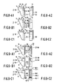
- Figs. 8 and 9 illustrate how simple mechanical blocking means of a drive apparatus can cooperate with cassettes provided with distinctive features of the types illustrated in Fig. 3 and 6 respectively.
- Fig. 8 the direction in which the cassette is moved as it is loaded into a drive apparatus is indicated by an arrow 28.
- Figs. 8-A1 and 8-A2 relate to a cassette of a first type, having the distinctive features illustrated in Fig. 3A, for cooperation with blocking means 29 of a first type (see also Fig. 1) in order to block cassettes 2 -3B of the second type and in order to give cassettes 2 -3A of the first type free access to the drive appartus.
- the blocking means take the form of a blocking pawl 30 which is pivotable about a pivotal axis 32 and which carries a blocking projection 34 at its end.
- the blocking pawl is intended for use in drive apparatuses of the type illustrated in Fig.
- the blocking pawl is pivotable about the pivotal axis between the blocking position shown in Figs. 1 and 8-A1, in which the blocking projection 34 is situated in the guide path 40, and a free position, in which the blocking pawl is situated outside the guide path.
- This free position is not illustrated in the drawing and requires a pivotal movement from the blocking position shown in the direction indicated by the arrow 42.
- the blocking pawl 30 is urged towards the blocking position by urging means in the form of a pressure spring 44, which acts against a portion 46 of the blocking pawl. For the sake of clarity neither the spring 44 nor the portion 46 are shown in Fig. 8.
- the projection 34 of the blocking pawl 30 is situated in the path 40 of the distinctive features of a cassette inserted in the correct orientation.
- the projection 34 then projects into the guide path 40 over a distance smaller than half the height h of the cassette so that, as the bevelled portion 22-3A cooperates with the projection 34, the blocking pawl is urged from the blocking position towards the free position in the direction indicated by the arrow 42 against the force of the spring 44 and consequently does not impede complete introduction of the cassette into the drive apparatus. If it is attempted to load a cassette 2 -3B of the second type into the drive apparatus the projection 34 will abut against the abutment wall 24-3B and thereby block insertion of the cassette into the drive apparatus.
- the projection 34 will also block insertion of a cassette if this cassette is not introduced into the slot 38 in the correct orientation, because no bevelled portion is present at the location of the corner 18 at the front of the cassette and at the location of the corners 48 and 50 at the rear of the cassette to urge the blocking pawl into the free position.
- the blocking pawl 52 in Figs. 8-B1 and 8-B2 is fully identical to the blocking pawl 30 but is situated at the other side of the guide path.
- This blocking pawl comprises a blocking projection 54 and is pivotable from the illustrated blocking position to the free position in the direction indicated by the arrow 56. It will be evident from the foregoing that drive apparatuses of the type illustrated in Fig. 1 but comprising a blocking pawl 52 are suitable for cooperation with correctly oriented cassettes 2 -3B of the second type.
- the blocking pawl 58 illustrated in Figs. 8-C1 and 8-C2 is of a slightly different type.
- This blocking pawl is also intended for use in conjunction with a drive apparatus having a front panel formed with a slot for the passage of cassettes to a guide path in the interior of the drive apparatus.
- the difference is that in the present case the projection 60 projects into the guide path over a distance larger than half the height h of a cassette.
- the blocking pawl 58 is suitable for use in conjunction with drive apparatuses of a third type, which accept both cassettes 2 -3A of the first type and cassettes 2 -3B of the second type.
- the projection 60 projects into the guide path over a distance larger than half the height h of the cassette the projection will always cooperate with the inclined surface 22 of the cassette when the cassette has been inserted in the correct orientation. In the case of an incorrectly oriented cassette the projection 60 will not cooperate with a corner of the cassette having a bevelled portion and will consequently block this cassette effectively.
- Figs.8-C1 and 8-C2 show the situation in which the blocking pawl 58 cooperates with a cassette 2 -3C of the third type. It will be obvious that the blocking pawl 58 also cooperates correctly with cassettes of this type. Such cassettes are not blocked by a blocking pawl 30 or a blocking pawl 52 because at the location of the blocking projection 34 or 54 the can cooperate with the inclined wall 22-3C. It is to be noted that the blocking pawl 58 may be arranged either underneath or above the guide path without the correct operation being impaired.
- Fig. 9 in the same way as Fig. 8, illustrates how the cassettes 2 -6A to 2 -6C cooperate with blocking pawls 62, 64 and 66 comprising projections 66, 70 and 72.
- Two of the blocking pawls 66 referred to as 66-1 and 66-2, comprise projections 72-1 and 72-2 respectively.
- the cassettes move in the direction of insertion indicated by the arrow 74.
- the pivotal movement of the blocking pawls from the illustrated blocking position to the free position is indicated by the arrows 76, 78, 80-1 and 80-2.
- Figs. 9-A1 and 9-A2 illustrate how a blocking pawl 62 allows a cassette 2 -6A of the first type to pass freely.
- a cassette 2 -68 of the second type will abut against the projection 68 with the abutment wall 24-68.
- the blocking projection 64 in Figs. 9-B1 and 9-B2 will allow the free passage of a cassette 2 -6B of the second type, but will block cassettes of the first type by cooperation with its abutment wall 24-6A.
- a special feature the blocking means shown in Figs. 9-C1 and 9-C2 is that they comprise a first and a second blocking pawl 66-1 and 66-2 respectively. They are coupled to one another by a coupling mechanism comprising two pinions 82-1 and 82-2.
- the blocking means 66 allow the passage of both cassettes 2 -6A of the first type and cassettes 2 -6B of the second type by cooperation of the projection 62-1 with the inclined wall 22-6A and of the projection 62-2 with the inclined wall 22-6B respectively. If the cassette is loaded in a wrong orientation introduction of the cassette will be inhibited by cooperation of the projections 72-1 and 72-2 with a transverse wall of the cassette.
- Figs .9-C1 and 9-C2 illustrate the coooperation between a cassette 2 -6C of a third type and the blocking means 66-1 and 66-2.
- Such a cassette will not be blocked by the blocking pawls 62 and 64 because one of the two inclined surfaces 22-6C will always cooperate with the respective blocking projections 68 and 70.
- a drive apparatus 84 has a front panel 86 formed with a slot 88 for the passage of cassettes to a guide path 90 in the interior of the drive apparatus.
- the system includes cassettes 92 which bear much resemblance to the cassettes 2 , but now they comprise with distinctive features in the form of a sticker 96 applied to the side wall 94 and provided with a bar-code pattern 98 comprising of a number of black lines on a white background.
- the drive apparatus 84 comprises scanning means arranged near the drive guide 90 to detect the type and the presence of the bar-code 98, which scanning means comprise an optical bar-code reader 100.
- Blocking means 102 are provided, comprising a blocking pawl 104 which under control of the bar-code reader 100 is electromagnetically movable between a blocking position in the guide path 90, see Fig. 15, and a free position outside the guide path.
- the blocking pawl 104 is moved from the blocking position to the free position under the influence of the output signal. In any other case the blocking pawl will inhibit insertion of a cassette.
- Fig. 16 is a block diagram of the circuit arrangement which controls the cooperation between the bar-code reader 100 and the electromagnetic blocking means 102.
- the bar-code reader comprises an optical system 106 by means of which a light beam can be projected onto the sticker 96.
- the reflected light is modulated by the bar-code 98 and the light thus modulated is received by the bar-code reader.
- Opto-electronic means in the bar-coder reader generate an output signal, represented symbolically by an arrow 108, which output signal is representative of the information contained in the bar-code.
- This output signal is applied to a decision circuit 110, which compares the bar-code information thus presented with information stored in the memory 112.
- the distinctive features of the cassette types to be accepted by the drive apparatus 84 are stored in a suitably encoded manner in a memory 112.
- the detected distinctive features are compared with those in the memory 112 by means of the decision circuit 110. Only if correspondence is detected by the decision circuit will an output signal 114 be supplied to an amplifier 116, which subsequently applies an amplified control signal to a control circuit 120 for the blocking means 102.
- the control circuit finally energises the electromagnetic blocking means 102, causing the blocking pawl 104 to be moved to the free position out of the guide path 90.
- further external signals such as for example those represented by the arrows 122 and 124, may be applied to the control unit 120, for example for service purposes or for remote control of the blocking means.
- a system of the type as illustrated in Figs. 15 and 16 has a very high flexibility.
- the system may include an unlimited number of cassette types, the sub-category of features stored in encoded form in the memory 112 defining for which sub-category of cassette types the drive apparatus is suitable.
- the scanning means and the blocking means may be of an entirely different type than shown.
- the system may include drive apparatuses of entirely different internal constructions but which have in common that they accept only one specific cassette type or a specific number of cassette types belonging to a system.
- the invention also relates to systems in which the drive apparatus does not comprise a front panel with a slot but has other means for inserting a cassette.
- Fig. 10 shows a drive apparatus 122 belonging to a system in accordance with the invention, which apparatus has a loading compartment 124.
- the drive apparatus has a front panel 126 formed with a slot 128 through which the loading compartment 124 can be moved inward in the direction indicated by the arrow 130.
- This type of drive apparatus like the drive apparatus shown in Fig. 1, is therefore suitable for incorporation in larger systems.
- a loading compartment which is situated at the upper side of the drive apparatus and which may be provided with a cover to close the compartment.
- such a top-loader should be accessible from the top, at least from the exterior, and is therefore not suitable for incorporation in a larger system, unless it is situated at the outside of such a larger system.
- the loading compartment 124 is constructed to accept cassettes 2 -3B.
- projecting means are provided in the form of a rectangular block 132 on which a bevelled triangular block 134 is arranged.
- the rectangular block 132 is engageable in the recess 26-3B of the cassette 2 -3B and the triangular block 134 is the complement of the bevelled portion 22-3B.
- the compartment accepts the cassette only when the cassette is inserted into the loading compartment 124 in a correct orientation. In any other orientation parts of the cassette abut against a portion 136 of the loading compartment which extends over the projecting means.
- the cassette 2 -6A and 2 -6C belonging to the system can never be correctly inserted into the loading compartment 124 because these cassettes do not have recesses suitable for engagement with the rectangular block 132.
- Figs. 11 to 14 show alternative cassettes 138 and 140 of a first type and a second type respectively belonging to an alternative system in accordance with the invention.
- the cassettes are intended for accommodating a disc-shaped information carrer and may comprise a slide 142 and 144 respectively, which is movable over the exterior of the cassette between a closed position and an open position, shown in the drawing.
- the cassette 138 has distinctive features of the first type arranged at both front corners of the cassette. They resemble those in Fig.
- the blocking means comprise two hook-shaped blocking pawls 156 and 158 at opposite sides of the cassette. In the drawing these pawls are shown in the blocking position but they are pivotable into the free position about the pivotal axes 164 and 166 respectively in the direction indicated by the arrows 160 and 162 respectively.
- the blocking means 156 and 158 are of a type which may be used in an apparatus in which the cassette is to be inserted through a slot in the front panel into a guide path inside the apparatus. They comprise a projection 168 and 170 respectively which projects into the guide path over a distance smaller than half the thickness of the cassette. In the situation illustrated in Figs. 11 and 12 the cassette 138 is not blocked by the blocking pawls 156 and 158. In any other orientation than shown the cassette will be blocked.
- the cassette 140 in Fig. 13 has distinctive features of the second type at only one corner at the front of the cassette. These features comprise a bevelled portion 172 over the full height of the cassette.
- the associated single blocking pawl 174 is pivotable from the blocking position shown into a free position about the pivotal axis 176 in the direction indicated by the arrow 178. At the free end the blocking pawl carries a projection 180 which projects into the guide path over a distance larger than half the thickness of the cassette. In the illustrated situation insertion of the cassette 140 is not inhibited by the blocking pawl 174. Blocking will be effected in any other than the correct orientation shown.
- the blocking means shown in Fig. 11 will not accept the cassette shown in Fig. 13 because, even when the cassette 140 of the second type is inserted in the correct orientation, the blocking pawl 158 will abut against the front wall 182 of the cassette and will consequently block this cassette. In any other orientation at least one of the two blocking pawls 156 and 158 will also block the cassette 140 . Conversely, the blocking means shown in Fig. 13 will inhibit acceptance of the cassette 138 of the first type shown in Fig. 11. Indeed, even when the cassette 138 is inserted in the correct orientation the projection 180 of the block pawl 174 will cooperate with the abutment wall 150 to block the cassette. In any other orientation the blocking pawl 174 will also inhibit insertion of the cassette.
- a drive apparatus of a third type which is suitable for cooperation with cassettes 138 of the first type and with cassettes 140 of the second type.
- Such a drive apparatus need have only one blocking pawl arranged at the same location as the blocking pawl 174 in Fig. 13 but having the shape of the blocking pawl 156 in Fig. 11.
- cassettes are used which are all of a uniform standard type but for certain standardized distinguishing features so that they may selectively cooperate with drive apparatus of different standardized types.
- the nature of the information carrier may be different from a disc shaped optically readable medium as shown in the drawing and could be of any suitable kind, for exmaple a magnetic disc or an optically, magnetically or otherwise readable tape or band, etc..
- the cassette may contain an electronic memory device such as a ROM or a RAM chip which may be accessed via electrical contacts situated on the outside of a cassette wall so that they may be scanned by mechanical sliding contact means of the apparatus.
- the distinguishing feature in such an embodiment will comprise distinguishing information present in the chip.
- Motor controlled means may be used to transport the cassette into and oout of the apparatus.
- the 124 in Fig. 10 for example may be motor driven.
- the slide may be combined with the embodiment of Figs. 15-16 by providing an aperture or a transparant part in a side wall of the slide to permit optical reacting of the bar-code.
- the blocks 132, 134 of the slide are no longer needed in such an embodiment.
- the control circuit 120 may be used to enable/disable the motordrive of the slide, this blocking acceptance of a cassette if necessary.
Abstract
Description
- The invention relates to a system for recording and/or reading signals on/from information carriers in cassettes, comprising cassettes of a first type and cassettes of a second type, said two types of cassettes being substantially identical in dimensions and shape apart from local distinctive features of a first type and a second type respectively, which system further comprises drive apparatuses constructed for cooperation with a cassette after insertion of a cassette in a correct orientation.
- A system of the type defined in the opening paragraph is known as the Compact Cassette system for recording and/or reproducing audio signals on/from magnetic tapes accommodated in cassettes. The system comprises cassettes containing different types of magnetic tape. A first type of cassette belonging to this system contains magnetic tape provided with a magnetic layer on an iron-oxide base. A second type of cassette contains chromium-dioxide magnetic tape. The two types of magnetic tape have different magnetic properties, as a result of which the drive apparatus should be adapted to the type of magnetic tape in use. The adaptation mainly affects the magnetic head and, more in particular, the setting of the bias current through the coil of the magnetic head. The drive apparatus may comprise an automatic device for adapting the bias current. Both types of cassettes have distinctive features to distinguish between the magnetic tapes used in the two types. The distinctive feature in cassettes containing chromium-dioxide tape is constituted by a cut-out in the rear wall of the cassette. Cassettes containing iron-oxide tapes can differ in that they do not have such a cut-out. A drive appartus which is suitable for cooperation with each of the two types of magnetic tape may comprise scanning means which detect the presence or absence of said cut-out in the rear wall of the cassette and which automatically selects the correct bias current.
- Another known system of the above type is the V2000 video-recorder system. This system employs three types of cassettes containing different lengths of magnetic tape. A pattern of apertures in the main walls of the cassettes (see United States Patent Specification US-PS 4,339,776, PHO 78.513, herewith incorporated by reference) can be detected by a drive apparatus by scanning the apertures to determine the length of the magnetic tape contained in the cassette being used.
- In the aforementioned prior-art systems the cassettes can be distinguished from one another in that specific apertures in the cassette housing are present or absent. For the remainder, the cassettes are substantially identical to one another at least as regards their external dimensions and shape and therefore they can be loaded into any drive apparatus belonging to the system. However, there may be systems in which this is undesirable. The invention provides a solution to this problem and is characterized in that the system comprises drive apparatus of a first type which are constructed for cooperation with cassettes of the first type but not for cooperation with cassettes of the second type, and drive apparatus of a second type which are constructed for cooperation with cassettes of the second type but not suitable for cooperation with cassettes of the first type, and in that both types of drive apparatuses comprise blocking means of a first type and a second type respectively configured to cooperate with the distinctive features, so that the drive apparatus of the first type accept cassettes of the first type but do not accept cassettes of the second type and the drive apparatuses of the second type accept cassettes of the second type but do not accept cassettes of the first type, provided that said cassettes are inserted in a correct orientation, and in other cases block said cassettes.
- The advantage of the invention is that it is possible to employ systems of the type defined in the opening paragraph in conjunction with cassettes which may contain entirely different information carriers, evertheless enabling the cassettes and the drive apparatuses to be assembled largely from identical parts. The presence of the distinctive features on the cassettes and the associated blocking means in the drive apparatuses makes it possible to effectively prevent a cassette from being loaded into a drive apparatus which is not intended for the relevant information carrier, and in addition, may prevent a cassette from being loaded into a drive apparatus in an incorrect orientation. The system in accordance with the invention is suitable, for example, for use in conjunction with optically readable information carriers. These information carriers may be of such a different nature that the drive apparatuses and the digital electronic devices employed therein should be adapted to a considerable extent to the information carriers being used. For example, the cassette of the first type may accommodate an optically readable disc of the standard CD-ROM type and cassettes of the second type may contain an erasable magneto-optical disc.
- Suitably, the system in accordance with the invention may be characterized in that the system comprises drive apparatuses of a third type constructed both for cooperation with cassettes of the first type and with cassettes of the second type and comprising blocking means of a third type configured to cooperate with both types of distinctive features of the cassettes, so that the drive apparatus accepts both cassettes of the first type and cassettes of the second type, provided that said cassettes are inserted in a correct orientation, and in other cases block the cassettes. When this embodiment is used a manufacturer can offer three types of drive apparatuses to the consumer, namely a first and a second type, which each only accept for cassettes of the first type and of the second type respectively, and drive apparatuses of a third type, which accept both cassettes of the first and the second type and which are therefore more intricate and expensive.
- Many known drive apparatuses comprise a front panel with an opening through which a cassette can be inserted into the interior of the drive apparatus. The advantage of such drive apparatuses is that they can readily be used as units to be built into larger apparatuses, for example computers or more extensive consumer-electronics systems. Particularly in view of the use of systems of this kind a further embodiment of the invention is characterized in that the cassettes are shaped substantially as a rectangular flat case having parallel main walls and transverse walls, including a front wall at the front which, in said correct orientation, faces a drive apparatus, the distinctive features of each of the two types of a cassette comprising a bevelled portion occupying a part of the height of the cassette at at least one of its front corners, and a further portion situated within the remainder of the height and comprising an abutment wall for cooperation with the blocking means. By arranging the distinctive features near at least one of the two front corners of the cassette it is possible to block the cassette, if necessary, immediately after insertion of the cassette into the drive apparatus. This largely precludes incorrect use of the cassette and possible damage to the drive apparatus.
- An interesting embodiment of the invention is characterized in that the distinctive features of each of the two cassettes types comprise a recess situated within said remainder of the height of the cassette, which recess opens towards the front of the cassette and is bounded by an abutment wall at the side which is remote from the front of the cassette. As will become apparent hereinafter, this embodiment can be used advantageously, for example, in systems comprising a third drive apparatus which accepts both cassettes of the first type and of the second type.
- In many cases an embodiment of the invention will be preferred, which is characterized in that the distinctive features are situated at only one of the two front corners of the cassette, and in that in cassettes of the first type the bevelled portion is situated at the location where said further portion is situated in the case of cassettes of the second type, and vice versa. As a result of the use of distinctive features at only one of the two front corners of the cassette the drive apparatuses also require blocking means at one side only. An even more important advantage may be that this embodiment is very suitable for cassettes of a type in which a shutter is movable over the exterior of the cassette from the centre position to a position near one of the corners of the cassette. The relevant corner is then less suitable for the provision of distinctive features. A cassette comprising an external shutter is known, for example, from European Patent Application EP 0,255,185 A1 (PHQ 86.015, herewith incorporated by reference) for use in conjunction with a disc-shaped optically readable information carrier.
- The last-mentioned embodiment can be improved even further when, in addition it is characterized in that the bevelled portion is situated in a plane which locally truncates a corner of the cassette and which extends perpendicularly to the main walls of the cassette, and in that said recess opens both towards the front and towards the side. As will be explained hereinafter with reference to the drawings this embodiment is very suitable, for systems comprising a third drive apparatuses which accept both cassettes of the first type and cassettes of the second type.
- An advantageous embodiment of the invention is characterized in that the system comprises drive apparatuses of at least one of the said types, having a front panel with a slot for the passage of cassettes to a guide path in the interior of the drive apparatus, in that the blocking means comprise a blocking pawl which is movable between a blocking position in the guide path and a free position outside the guide path, and urging means which urge the blocking pawl towards the blocking position, and in that the blocking pawl is situated in the path of the distinctive features of a cassette inserted in the correct orientation and projects into the guide path over a distance smaller than half the height of a cassette, so that as it cooperates with a bevelled portion belonging to the distinctive features of a cassette the blocking pawl is urged from the blocking position to the free position and as it cooperates with an abutment wall belonging to the distinctive features or with a transverse wall of the cassette the blocking pawl inhibits insertion of the cassette. In this embodiment the drive apparatuses advantageously utilise the bevelled portion constituting a distinctive feature of an associated cassette to urge a simple blocking pawl from a blocking position to a free position. In this way the blocking means require only a few parts, which moreover can be of simple construction. No separate means are required for moving the blocking pawl to the free position, the required energy being furnished by a person who inserts the cassette into the apparatus through the slot. A further embodiment, derived from the foregoing embodiment, is characterized in that the blocking means comprise a first and a second blocking pawl and a coupling mechanism between the blocking pawls to transmit the movements of one blocking pawl to the other blocking pawl substantially in a one-to-oine ratio, so that the blocking pawls are movable from the blocking position to the free position and from the free position to the blocking position in a synchronised manner. In this embodiment the blocking means comprise a combination of the blocking means of the drive apparatuses of the first type and of the second type, the blocking pawls being coupled to each other in such a way that they block neither a cassette of the first type nor a cassette of the second type, provided that said cassette is inserted in the correct orientation.
- Alternatively, another embodiment may be used, which is characterized in that a drive apparatus of a third type, belonging to the system, has a front panel with a slot for the passage of cassettes to a guide path in the interior of the drive apparatus, and in that the blocking means of the third type comprise a blocking pawl which is movable between a blocking position in the guide path and a free position outside the guide path, and urging means which urge the blocking pawl towards the blocking position, and in that the blocking pawl is situated in the path of the distinctive features of a cassette inserted in the correct orientation and projects into the guide path over a distance larger than half the height of a cassette, so that as it cooperates with the distinctive features of a cassette belonging to whichever of the two said cassette types the blocking pawl is urged from the blocking position to the free position by the bevelled portion, and as it cooperates with a transverse wall of a cassette inserted in an incorrect orientation inhibits insertion of the cassette. In this embodiment the blocking means need not be duplicated owing to the use of blocking means of a slightly different type.
- A system in accordance with the invention, which differs from the preceding systems, is characterized in that the system comprises a drive apparatus of said type having a front panel with a slot for the passage of cassettes of said type to a guide path in the interior of the drive apparatus, in that near the guide path the drive apparatus comprises scanning means producing an electric output signal, for detecting the type and the presence of the distinctive features of a cassette and in that the blocking means comprise a blocking pawl which under control of the scanning means is electromagnetically movable between a blocking position in a guide path and the free position outside the guide path, so that as the distinctive features of a cassette to be accepted are scanned by the scanning means the blocking pawl is moved from the blocking position to the free position under the influence of the output signal and in other cases the blocking pawl inhibits insertion of the cassette. The blocking means used in this embodiment are more intricate than in embodiments in which the blocking means comprise exclusively mechanical parts, but this has the advantage that it enables the use of distinctive features of an entirely different nature, which can be scanned mechanically, magnetically, optically, inductively or otherwise by the drive apparatus. If desired, the distinctive features can then be scanned without mechanical contact, for example in the case of optical or magnetic scanning. The distinctive features of the cassettes may comprise, for example, features applied to the exterior of the cassette housing, such as a magnetic strip or a sticker printed with optically detactable features, for example a bar code. Moreover, this embodiment enables a wide variety of cassettes to be used. It enables the use of drive apparatuses suitable for use in conjunction with different sub-categories of the category of cassette types belonging to the system, for example suitable for cassettes of a second and a third type but not suitable for cassettes of a first and a fourth type, etc. This embodiment is eminently suitable for apparatuses employing electric motor controlled means to transport the cassette into and out of the apparatus. The electric ouptu of the scanning means can be used to control the motor control.
- When cassettes are employed having distinctive features comprising a recess at a corner of a cassette, an embodiment of the invention may be used, which is characterized in that the system comprises a drive apparatus having a loading compartment for the insertion of cassettes, projecting means being arranged in a corner of the loading compartment and being engageable in said recess of a correctly oriented cassette of a type corresponding to the drive apparatus. Drive apparatuses having a loading compartment may comprise, for example, a loading compartment which forms an integral part of the housing of the apparatus and which may be provided with a cover to close the compartments. Alternatively, the loading compartment may be constructed as a slide which is movable into and out of the housing of the drive apparatus, so that drive apparatuses of this type constitute an alternative for drive apparatuses having a slot in the front panel.
- Embodiments of the invention will now be described in more detail, by way of non limitative example, with reference to the accompanying diagrammatic drawings in which:
- Fig. 1 is a perspective view of a drive apparatus and a cassette belonging to a system in accordance with the invention, the cassette being shown in a position where it is about to be inserted in a correct position into the drive apparatus through a slot in the front,
- Fig. 2 is a perspective view of a cassette, of which a corner portion situated within an oval is shown in broken lines, within which oval distinctive features of a type as illustrated in Figs. 3A to 7B may be situated,
- Figs. 3A to 7B are perspective views showing distinctive features which may be provided within the oval indicated in Fig. 2,
- Figs.8-A1 to 8-C1 are plan views of a part of a cassette provided with distinctive features as shown in Figs. 3A to 3C respectively, and of the associated blocking means of a drive apparatus,
- Figs. 8-A2 to 8-C2 are side views corresponding to Figs. 8-Al to 8-C1,
- Figs. 9-A1 to 9-C1 are similar to Figs. 8-Al to 8-C1 but relate to cassettes having distinctive features as illustrated in Figs. 6A to 6C,
- Fig. 10 is a perspective view of the front part of a drive apparatus comprising an extensible cassette-loading compartment.
- Fig. 11 is a plan view of a cassette having distinctive features near two corners and of the associated blocking means of a drive apparatus,
- Fig. 12 is a front view in accordance with the arrow XII in Fig. 11,
- Fig. 13 is a plan view similar to that of Fig. 11, showing a cassette belonging to the same system but having distinctive features of the second type, and showing the associated blocking means of the second type,
- Fig. 14 is a view in accordance with the arrow XIV in Fig. 13,
- Fig. 15 is a perspective view similar to that shown in Fig. 1, showing another embodiment of the invention, and
- Fig. 16 is a block diagram illustrating how the system of Fig. 15 is controlled.
- In Figs. 1 to 7B use is made of a coherent system of reference numerals for the cassettes and their distinctive features. The cassettes are all of a construction as illustrated in Fig. 2. To distinguish between the cassettes, the
reference numeral 2 for the cassette is followed by the number of the Figure in which the distinctive features are illustrated. For example, the cassette 2 -3A in Fig. 1 has the distinctive features shown in Fig. 3A. Furthermore, corresponding parts bear the same reference numerals followed by the Figure number of the embodiment. For example, all the first distinctive features in Figs. 1 to 7B bear the reference numeral 22 followed by a Figure number, for example 22-3A in Fig. 3A. If specific parts are referred to in general, the Figure number is not affixed. For example, reference may be made tocassettes 2 having first distinctive features 22. If reference is made to Fig. 3, this is to be understood to mean Figs. 3A to 3C. The same applies to the other Figures. - Fig. 1 shows a
cassette 2 provided with an information carrier in the form of a disc 4, and adrive apapratus 6 . The cassette and the drive apparatus belong to a system for recording or reading signals in accordance with the invention. The cassette is shaped substantially as a rectangular flat case having amain wall 8 at the upper side and a similar main wall, not shown, at the under side. The cassette further comprises arear wall 10, a right-hand side wall 11 which extends parallel to a left-hand side wall which is not visible in the drawings, as well as afront wall 14, see also Fig. 2. Aslide 16 is movable over the main walls from a mid position, as shown, to an open position near thecorner 18 of the cassette. The system further includes cassettes whose external dimensions and shapes are substantially identical to those of the cassette shown, if the local distinctive features are ignored. The distinctive features of the cassette shown in Fig. 1 are situated at the corner of the cassette which is situated opposite thecorner 18 and will be described in more detail hereinafter. Thedrive apparatus 6 is constructed for cooperation with thecassette 2 . - In addition to the
drive apparatus 6 the system comprises further drive apparatuses, not shown, of another type which are not suitable for cooperation with the cassett 2-3A but which are constructed for cooperation with the afore-mentioned cassettes 2-3N of the second type, which differ from the cassette 2-3A only with respect to the dictinctive features. - Referring now to Figs. 3 to 9, different distinctive features and blocking means will be described, which can be used in conjunction with, for example, cassettes of
type 2 as shown in Fig. 2. For thecassette 2 of Fig. 2 the distinctive features illustrated in Figs. 3 to 7 are situated within an oval 20. Figs. 3 to 7 exclusively relate to the distinctive features of the cassette situated within said ovals. - Figs. 3A to 3C relate to three types of distinctive features suitable for three types of cassettes belonging to a system in accordance with the invention, the third type of cassette having the distinctive features illustrated in Fig. 3C and being constructed for cooperation with drive apparatuses of both the first type and the second type. In this embodiment of the system the distinctive features of the cassettes of the first type comprise a bevelled portion 22-3A and the distinctive features of the second type, see Fig. 3B, comprise a bevelled portion 22-3B. The bevelled portion covers only a part of the height h of the cassette, namely about half the height. The distinctive features shown in Fig. 3C comprise a bevelled portion 22-3C which extends over the full height h of the cassette. The distinctive features of the first and the second type comprise a further portion situated within the remainder of the height and comprising an abutment wall 24-3A and 24-3B respectively for cooperation with the blocking means. The distinctive features comprise a recess 26-3A and 26-3B respectively siatuated within said remainder of the height h of the cassette and opening towards the front of the cassette. The abutment walls 24-3A and 24-3B are situated at the side which is remote from the front side of the cassette.
- These distinctive features, like all the distinctive features as shown in Figs. 3 to 7, are situated at only one of the two front corners of the
cassette 2. As will become apparent after a comparison between Figs. 3A and 3B, the bevelled portion in cassettes of the first type, see Fig. 3A, is situated at the location where the further portion is situated in cassettes of the second type, see Fig. 3B, and vice versa. This also applies to the distinctive features illustrated in Figs. 4 to 7. In the cassette shown in Fig. 3C, which is a cassette of a third type belonging to the system which also includes the cassettes as shown in Figs. 3A and 3B, the bevelled portion 22-3C occupies the full height h of the cassette. - The abutment wall 24 of the distinctive features shown in Fig. 4 is situated at the front side of the cassette, in line with the
front wall 14. This means that there is no recess similar to the recess 26 in Figs. 3. In a system comprising the distinctive features shown in Fig. 4 it is also possible to employ a cassette of a third type, see the distinctive features shown in Fig. 3C. Thus, it is also possible to obtain a system comprising cassettes of five types, having the distinctive features illustrated in Figs. 3 and 4. The associated four types of drive apparatus may comprise four types of blocking means for cooperation with cassettes having the distinctive features illustrated in Figs. 3A, 3B, 4A and 4B, respectively. The fifth type of cassette has the distinctive features illustrated in Fig. 3C and is accepted by all four types of drive apparatus. - In the case of the distinctive features shown in Figs. 3 and 4 the bevelled portion 22 is situated in a plane which locally truncates a corner portion of the
cassette 2 and which extends perpendicularly to themain walls 8 of the cassette. Said recesses 26 open both towards the front and towards the sides. The advantage of these embodiments will be described in detail hereinafter. - The distinctive features illustrated in Fig. 5 comprise an inclined wall 22 which does not truncate a corner of the cassette and which does not extend perpendicularly to the
main walls 8 of the cassette. The inclined wall 22 does not not extend up to theside wall 12 of the cassette, so that this side wall is imperforate. The inclined wall 22 is situated in a part of the cassette which occupies slightly less than half the thickness of the cassette. At the opposite side of the cassette a recess 26 is situated with an abutment 24. Again these recesses do not open towards theside 12 of the cassette. - The distinctive features illustrated in Fig. 6 are substantially identical to those illustrated in Fig. 5, except that now the distinctive features extend up to the
side wall 12 of the cassette, so that the side wall is partly open at this location. - The embodiment shown in Fig. 7 again resembles that shown in Fig. 6, except that no recess 26 is used, so that the abutment wall 24 is situated in the same plane as the
front wall 14 of the cassette. - Figs. 8 and 9 illustrate how simple mechanical blocking means of a drive apparatus can cooperate with cassettes provided with distinctive features of the types illustrated in Fig. 3 and 6 respectively.
- In Fig. 8 the direction in which the cassette is moved as it is loaded into a drive apparatus is indicated by an
arrow 28. - Figs. 8-A1 and 8-A2 relate to a cassette of a first type, having the distinctive features illustrated in Fig. 3A, for cooperation with blocking means 29 of a first type (see also Fig. 1) in order to block cassettes 2-3B of the second type and in order to give cassettes 2-3A of the first type free access to the drive appartus. The blocking means take the form of a blocking
pawl 30 which is pivotable about apivotal axis 32 and which carries a blockingprojection 34 at its end. The blocking pawl is intended for use in drive apparatuses of the type illustrated in Fig. 1, having afront panel 36 with aslot 38 for the passage of cassettes to a guide path 40 in the interior of the drive apparatus, which path is symbolically represented in broken lines. The blocking pawl is pivotable about the pivotal axis between the blocking position shown in Figs. 1 and 8-A1, in which the blockingprojection 34 is situated in the guide path 40, and a free position, in which the blocking pawl is situated outside the guide path. This free position is not illustrated in the drawing and requires a pivotal movement from the blocking position shown in the direction indicated by thearrow 42. The blockingpawl 30 is urged towards the blocking position by urging means in the form of apressure spring 44, which acts against aportion 46 of the blocking pawl. For the sake of clarity neither thespring 44 nor theportion 46 are shown in Fig. 8. - As is shown in Fig. 1 and Fig. 8-A1 the
projection 34 of the blockingpawl 30 is situated in the path 40 of the distinctive features of a cassette inserted in the correct orientation. Theprojection 34 then projects into the guide path 40 over a distance smaller than half the height h of the cassette so that, as the bevelled portion 22-3A cooperates with theprojection 34, the blocking pawl is urged from the blocking position towards the free position in the direction indicated by thearrow 42 against the force of thespring 44 and consequently does not impede complete introduction of the cassette into the drive apparatus. If it is attempted to load a cassette 2-3B of the second type into the drive apparatus theprojection 34 will abut against the abutment wall 24-3B and thereby block insertion of the cassette into the drive apparatus. Theprojection 34 will also block insertion of a cassette if this cassette is not introduced into theslot 38 in the correct orientation, because no bevelled portion is present at the location of thecorner 18 at the front of the cassette and at the location of thecorners - The blocking
pawl 52 in Figs. 8-B1 and 8-B2 is fully identical to the blockingpawl 30 but is situated at the other side of the guide path. This blocking pawl comprises a blockingprojection 54 and is pivotable from the illustrated blocking position to the free position in the direction indicated by the arrow 56. It will be evident from the foregoing that drive apparatuses of the type illustrated in Fig. 1 but comprising a blockingpawl 52 are suitable for cooperation with correctly oriented cassettes 2-3B of the second type. - The blocking
pawl 58 illustrated in Figs. 8-C1 and 8-C2 is of a slightly different type. This blocking pawl is also intended for use in conjunction with a drive apparatus having a front panel formed with a slot for the passage of cassettes to a guide path in the interior of the drive apparatus. The difference is that in the present case theprojection 60 projects into the guide path over a distance larger than half the height h of a cassette. As a result of this the blockingpawl 58 is suitable for use in conjunction with drive apparatuses of a third type, which accept both cassettes 2-3A of the first type and cassettes 2-3B of the second type. Since theprojection 60 projects into the guide path over a distance larger than half the height h of the cassette the projection will always cooperate with the inclined surface 22 of the cassette when the cassette has been inserted in the correct orientation. In the case of an incorrectly oriented cassette theprojection 60 will not cooperate with a corner of the cassette having a bevelled portion and will consequently block this cassette effectively. - Figs.8-C1 and 8-C2 show the situation in which the blocking
pawl 58 cooperates with a cassette 2-3C of the third type. It will be obvious that the blockingpawl 58 also cooperates correctly with cassettes of this type. Such cassettes are not blocked by a blockingpawl 30 or a blockingpawl 52 because at the location of the blockingprojection pawl 58 may be arranged either underneath or above the guide path without the correct operation being impaired. - Fig. 9, in the same way as Fig. 8, illustrates how the cassettes 2-6A to 2-6C cooperate with blocking
pawls projections pawls 66, referred to as 66-1 and 66-2, comprise projections 72-1 and 72-2 respectively. During insertion the cassettes move in the direction of insertion indicated by thearrow 74. The pivotal movement of the blocking pawls from the illustrated blocking position to the free position is indicated by thearrows pawl 62 allows a cassette 2-6A of the first type to pass freely. However, a cassette 2-68 of the second type will abut against theprojection 68 with the abutment wall 24-68. Conversely, the blockingprojection 64 in Figs. 9-B1 and 9-B2 will allow the free passage of a cassette 2-6B of the second type, but will block cassettes of the first type by cooperation with its abutment wall 24-6A. A special feature the blocking means shown in Figs. 9-C1 and 9-C2 is that they comprise a first and a second blocking pawl 66-1 and 66-2 respectively. They are coupled to one another by a coupling mechanism comprising two pinions 82-1 and 82-2. As a result of this, the movements of one blocking pawl are transmitted to the other blocking pawl substantially in a 1:1 ratio, so that the blocking pawls can perform a synchronised movement from the blocking position to the free position in the direction indicated by the arrows 80-1 and 80-2 and vice versa. As a result of this, the blocking means 66 allow the passage of both cassettes 2-6A of the first type and cassettes 2-6B of the second type by cooperation of the projection 62-1 with the inclined wall 22-6A and of the projection 62-2 with the inclined wall 22-6B respectively. If the cassette is loaded in a wrong orientation introduction of the cassette will be inhibited by cooperation of the projections 72-1 and 72-2 with a transverse wall of the cassette. Figs .9-C1 and 9-C2 illustrate the coooperation between a cassette 2-6C of a third type and the blocking means 66-1 and 66-2. Such a cassette will not be blocked by the blocking pawls 62 and 64 because one of the two inclined surfaces 22-6C will always cooperate with therespective blocking projections - The embodiments of the invention described in the foregoing each comprise blocking means formed by simple mechanical components. Figs. 15 and 16 show that entirely different embodiments are possible. Again a
drive apparatus 84 has afront panel 86 formed with aslot 88 for the passage of cassettes to aguide path 90 in the interior of the drive apparatus. In the embodiment shown the system includescassettes 92 which bear much resemblance to thecassettes 2 , but now they comprise with distinctive features in the form of asticker 96 applied to theside wall 94 and provided with a bar-code pattern 98 comprising of a number of black lines on a white background. Thedrive apparatus 84 comprises scanning means arranged near thedrive guide 90 to detect the type and the presence of the bar-code 98, which scanning means comprise an optical bar-code reader 100. Blocking means 102 are provided, comprising a blockingpawl 104 which under control of the bar-code reader 100 is electromagnetically movable between a blocking position in theguide path 90, see Fig. 15, and a free position outside the guide path. When the bar code of a cassette to be accepted is being scanned by the bar-code reader the blockingpawl 104 is moved from the blocking position to the free position under the influence of the output signal. In any other case the blocking pawl will inhibit insertion of a cassette. - Fig. 16 is a block diagram of the circuit arrangement which controls the cooperation between the bar-
code reader 100 and the electromagnetic blocking means 102. The bar-code reader comprises anoptical system 106 by means of which a light beam can be projected onto thesticker 96. The reflected light is modulated by the bar-code 98 and the light thus modulated is received by the bar-code reader. Opto-electronic means in the bar-coder reader generate an output signal, represented symbolically by anarrow 108, which output signal is representative of the information contained in the bar-code. This output signal is applied to adecision circuit 110, which compares the bar-code information thus presented with information stored in thememory 112. The distinctive features of the cassette types to be accepted by thedrive apparatus 84 are stored in a suitably encoded manner in amemory 112. The detected distinctive features are compared with those in thememory 112 by means of thedecision circuit 110. Only if correspondence is detected by the decision circuit will anoutput signal 114 be supplied to anamplifier 116, which subsequently applies an amplified control signal to acontrol circuit 120 for the blocking means 102. The control circuit finally energises the electromagnetic blocking means 102, causing the blockingpawl 104 to be moved to the free position out of theguide path 90. Moreover, further external signals, such as for example those represented by thearrows control unit 120, for example for service purposes or for remote control of the blocking means. - A system of the type as illustrated in Figs. 15 and 16 has a very high flexibility. In principle, the system may include an unlimited number of cassette types, the sub-category of features stored in encoded form in the
memory 112 defining for which sub-category of cassette types the drive apparatus is suitable. The scanning means and the blocking means may be of an entirely different type than shown. In principle, it is possible to design scanning means, for example optical scanning means, for cooperation with distinctive features as illustrated in Figs. 3 to 7. Thus, it is also possible to design a system comprising cassettes having distinctive features adapted to cooperate with simple mechanical blocking means but in addition with electrically controllable blocking means. Thus, the system may include drive apparatuses of entirely different internal constructions but which have in common that they accept only one specific cassette type or a specific number of cassette types belonging to a system. - The invention also relates to systems in which the drive apparatus does not comprise a front panel with a slot but has other means for inserting a cassette. For example, Fig. 10 shows a
drive apparatus 122 belonging to a system in accordance with the invention, which apparatus has aloading compartment 124. The drive apparatus has afront panel 126 formed with aslot 128 through which theloading compartment 124 can be moved inward in the direction indicated by thearrow 130. This type of drive apparatus, like the drive apparatus shown in Fig. 1, is therefore suitable for incorporation in larger systems. However, it is also possible to employ a loading compartment which is situated at the upper side of the drive apparatus and which may be provided with a cover to close the compartment. Obviously, such a top-loader should be accessible from the top, at least from the exterior, and is therefore not suitable for incorporation in a larger system, unless it is situated at the outside of such a larger system. - The
loading compartment 124 is constructed to accept cassettes 2-3B. In a corner of the loading compartment projecting means are provided in the form of arectangular block 132 on which a bevelled triangular block 134 is arranged. Therectangular block 132 is engageable in the recess 26-3B of the cassette 2-3B and the triangular block 134 is the complement of the bevelled portion 22-3B. The compartment accepts the cassette only when the cassette is inserted into theloading compartment 124 in a correct orientation. In any other orientation parts of the cassette abut against a portion 136 of the loading compartment which extends over the projecting means. The cassette 2-6A and 2-6C belonging to the system can never be correctly inserted into theloading compartment 124 because these cassettes do not have recesses suitable for engagement with therectangular block 132. - All the systems described so far comprise cassettes having distinctive features in only one corner of the cassette. Although in may cases this is definitely advantageous for the reasons given in the foregoing, it is not essential for the invention. For example, Figs. 11 to 14 show
alternative cassettes slide cassette 138 has distinctive features of the first type arranged at both front corners of the cassette. They resemble those in Fig. 4B and they comprise bevelledportions abutment walls 150 and 152, which form part of thefront wall 154 at the front of the cassette and which occupy the other half of the height of the cassette. The blocking means comprise two hook-shaped blockingpawls pivotal axes 164 and 166 respectively in the direction indicated by thearrows - The blocking means 156 and 158 are of a type which may be used in an apparatus in which the cassette is to be inserted through a slot in the front panel into a guide path inside the apparatus. They comprise a
projection 168 and 170 respectively which projects into the guide path over a distance smaller than half the thickness of the cassette. In the situation illustrated in Figs. 11 and 12 thecassette 138 is not blocked by the blockingpawls - The
cassette 140 in Fig. 13 has distinctive features of the second type at only one corner at the front of the cassette. These features comprise a bevelledportion 172 over the full height of the cassette. The associatedsingle blocking pawl 174 is pivotable from the blocking position shown into a free position about thepivotal axis 176 in the direction indicated by thearrow 178. At the free end the blocking pawl carries aprojection 180 which projects into the guide path over a distance larger than half the thickness of the cassette. In the illustrated situation insertion of thecassette 140 is not inhibited by the blockingpawl 174. Blocking will be effected in any other than the correct orientation shown. - The blocking means shown in Fig. 11 will not accept the cassette shown in Fig. 13 because, even when the
cassette 140 of the second type is inserted in the correct orientation, the blockingpawl 158 will abut against thefront wall 182 of the cassette and will consequently block this cassette. In any other orientation at least one of the two blockingpawls cassette 140. Conversely, the blocking means shown in Fig. 13 will inhibit acceptance of thecassette 138 of the first type shown in Fig. 11. Indeed, even when thecassette 138 is inserted in the correct orientation theprojection 180 of theblock pawl 174 will cooperate with the abutment wall 150 to block the cassette. In any other orientation the blockingpawl 174 will also inhibit insertion of the cassette. - In a system comprising cassettes of the first and the second type as illustrated in Figs. 11 to 14, it is possible to employ a drive apparatus of a third type which is suitable for cooperation with
cassettes 138 of the first type and withcassettes 140 of the second type. Such a drive apparatus need have only one blocking pawl arranged at the same location as the blockingpawl 174 in Fig. 13 but having the shape of the blockingpawl 156 in Fig. 11. - Apart from the embodiments shown in the drawing, many alternative embodiments are possible in which, in accordancewith the invention, cassettes are used which are all of a uniform standard type but for certain standardized distinguishing features so that they may selectively cooperate with drive apparatus of different standardized types. The nature of the information carrier may be different from a disc shaped optically readable medium as shown in the drawing and could be of any suitable kind, for exmaple a magnetic disc or an optically, magnetically or otherwise readable tape or band, etc..
- Many other kinds of distinguishing features may be used. For example, the cassette may contain an electronic memory device such as a ROM or a RAM chip which may be accessed via electrical contacts situated on the outside of a cassette wall so that they may be scanned by mechanical sliding contact means of the apparatus. The distinguishing feature in such an embodiment will comprise distinguishing information present in the chip.
- Motor controlled means may be used to transport the cassette into and oout of the apparatus. The 124 in Fig. 10 for example may be motor driven. The slide may be combined with the embodiment of Figs. 15-16 by providing an aperture or a transparant part in a side wall of the slide to permit optical reacting of the bar-code. The
blocks 132, 134 of the slide are no longer needed in such an embodiment. Thecontrol circuit 120 may be used to enable/disable the motordrive of the slide, this blocking acceptance of a cassette if necessary.
Claims (11)
Applications Claiming Priority (2)
| Application Number | Priority Date | Filing Date | Title |
|---|---|---|---|
| NL8802763 | 1988-11-10 | ||
| NL8802763A NL8802763A (en) | 1988-11-10 | 1988-11-10 | SYSTEM FOR RECORDING AND / OR READING SIGNALS ON DATA CARRIERS IN CASSETTES. |
Publications (2)
| Publication Number | Publication Date |
|---|---|
| EP0368416A1 true EP0368416A1 (en) | 1990-05-16 |
| EP0368416B1 EP0368416B1 (en) | 1995-02-22 |
Family
ID=19853198
Family Applications (1)
| Application Number | Title | Priority Date | Filing Date |
|---|---|---|---|
| EP89202822A Expired - Lifetime EP0368416B1 (en) | 1988-11-10 | 1989-11-08 | System for recording and/or reading signals on/from information carriers in cassettes |
Country Status (12)
| Country | Link |
|---|---|
| US (1) | US5325243A (en) |
| EP (1) | EP0368416B1 (en) |
| JP (1) | JP2679850B2 (en) |
| KR (1) | KR0175291B1 (en) |
| CZ (1) | CZ281416B6 (en) |
| DD (1) | DD285655A5 (en) |
| DE (1) | DE68921290T2 (en) |
| ES (1) | ES2071644T3 (en) |
| HK (1) | HK62196A (en) |
| NL (1) | NL8802763A (en) |
| RU (1) | RU2067323C1 (en) |
| SK (1) | SK279698B6 (en) |
Cited By (7)
| Publication number | Priority date | Publication date | Assignee | Title |
|---|---|---|---|---|
| EP0496511A2 (en) * | 1991-01-21 | 1992-07-29 | Sony Corporation | Disc cartridge |
| EP0690445A3 (en) * | 1994-06-29 | 1996-06-12 | Sony Corp | Disc cartridges |
| EP0703582A3 (en) * | 1994-09-20 | 1996-08-28 | Matsushita Electric Ind Co Ltd | Disk cartridge and tray for loading the same |
| EP0871176A1 (en) * | 1995-12-20 | 1998-10-14 | Fuji Photo Film Co., Ltd. | Magnetic disk cartridge and magnetic disk driving apparatus |
| EP1130593A2 (en) * | 2000-03-02 | 2001-09-05 | Sony Corporation | Disk cartridge mis-insertion discrimination |
| SG95593A1 (en) * | 1997-12-25 | 2003-04-23 | Sony Corp | Structure for preventing misinsertion of recording-medium cartridges |
| GB2388245A (en) * | 2002-05-01 | 2003-11-05 | Plasmon Lms Inc | Preventing insertion of cartridge into incompatible disk drive |
Families Citing this family (30)
| Publication number | Priority date | Publication date | Assignee | Title |
|---|---|---|---|---|
| DE4135371A1 (en) * | 1991-10-26 | 1993-04-29 | Thomson Brandt Gmbh | READER FOR A STATIC MEMORY OF A CASSETTE |
| US6101070A (en) * | 1993-09-30 | 2000-08-08 | Sony Corporation | Method and apparatus for determining information and a cassette for use therewith |
| US5548571A (en) * | 1994-10-03 | 1996-08-20 | Eastman Kodak Company | Method and apparatus for identifying data storage disks |
| US5675566A (en) * | 1994-10-31 | 1997-10-07 | Sony Corporation | Recording and/or reproducing apparatus and a cartridge for a recording medium |
| US5638228A (en) * | 1995-02-14 | 1997-06-10 | Iomega Corporation | Retroreflective marker for data storage cartridge |
| US5986838A (en) | 1995-02-14 | 1999-11-16 | Iomega Corporation | Thin retroreflective marker for data storage cartridge |
| US6067214A (en) * | 1995-02-14 | 2000-05-23 | Iomega Corporation | Data cartridge marker for foreign object detection |
| US6097562A (en) * | 1995-02-14 | 2000-08-01 | Iomega Corporation | Disk drive for detecting a retroreflective marker on a data storage cartridge |
| US5710681A (en) * | 1995-06-07 | 1998-01-20 | International Business Machines Corporation | Pivot bearing having no moving parts for use in a high density data tape drive |
| US5793573A (en) * | 1995-06-07 | 1998-08-11 | International Business Machines Corporation | Hybrid actuator servo actuated tape drive having a pivotally mounted motion transmission member |
| US5677806A (en) * | 1995-06-07 | 1997-10-14 | International Business Machines Corporation | Head locking apparatus in a servo system so that the head can read and write data on a tape without servo trucks |
| JPH09297984A (en) * | 1996-05-02 | 1997-11-18 | Alps Electric Co Ltd | Recording and reproducing device |
| US5901134A (en) * | 1996-02-20 | 1999-05-04 | Sony Corporation | Disk cartridge |
| TW473706B (en) | 1997-07-14 | 2002-01-21 | Sony Corp | Structure for preventing misinsertion of disc cartridges |
| US6181662B1 (en) | 1997-09-26 | 2001-01-30 | Iomega Corporation | Latent irradiance discrimination method and marker system for cartridgeless data storage disks |
| US6091563A (en) * | 1997-09-26 | 2000-07-18 | Iomega Corporation | Latent illuminance discrimination marker system for data storage cartridges |
| US6359745B1 (en) | 1997-09-26 | 2002-03-19 | Iomega Corporation | Latent illuminance discrimination marker system for data storage cartridges |
| US6264107B1 (en) | 1997-09-26 | 2001-07-24 | Iomega Corporation | Latent illuminance discrimination marker system for authenticating articles |
| US6201662B1 (en) | 1998-09-25 | 2001-03-13 | Iomega Corporation | Latent illuminance discrimination marker with reflective layer for data storage cartridges |
| US5992011A (en) * | 1997-10-29 | 1999-11-30 | Iomega Corporation | Method of assembling a baffle to a detector for detecting a retroreflective marker |
| JPH11317039A (en) * | 1998-02-16 | 1999-11-16 | Sanyo Electric Co Ltd | Disk cartridge and disk player |
| US6297923B1 (en) | 1998-11-13 | 2001-10-02 | Iomega Corporation | Disk-cartridge detection system incorporating an angled light emitter/detector |
| US6693858B2 (en) * | 2001-03-21 | 2004-02-17 | Hewlett-Packard Development Company, L.P. | Data cartridge detector |
| US7340749B2 (en) * | 2002-12-03 | 2008-03-04 | Hewlett-Packard Development Company, L.P. | Method and apparatus to detect presence of or a size of a data cartridge |
| KR100490437B1 (en) | 2003-07-22 | 2005-05-18 | 삼성전자주식회사 | A loading apparatus for disk cartridge |
| KR100517505B1 (en) * | 2003-07-22 | 2005-09-28 | 삼성전자주식회사 | A loading apparatus for disk cartridge |
| US7088539B2 (en) * | 2003-11-18 | 2006-08-08 | Hewlett-Packard Development Company, L.P. | Apparatus for detecting media |
| JP2006268918A (en) * | 2005-03-22 | 2006-10-05 | Fuji Photo Film Co Ltd | Recording disk cartridge and disk drive |
| US20070272758A1 (en) * | 2006-05-23 | 2007-11-29 | Kulkarni Subodh K | Cartridge and system for duplicating optical disks |
| JP4748038B2 (en) * | 2006-11-24 | 2011-08-17 | ソニー株式会社 | Playback device |
Citations (8)
| Publication number | Priority date | Publication date | Assignee | Title |
|---|---|---|---|---|
| US4261527A (en) * | 1978-12-18 | 1981-04-14 | Ford Aerospace & Communications Corporation | Apparatus for preventing damage to a tape player head |
| WO1981001907A1 (en) * | 1980-08-05 | 1981-07-09 | Budapesti Radiotechnikai Gyar | Indicator device for cassettes loaded with magnetical information carrier |
| US4602299A (en) * | 1982-08-25 | 1986-07-22 | Canon Kabushiki Kaisha | Recording apparatus with device for detecting the status of a recording medium |
| EP0210629A2 (en) * | 1985-07-29 | 1987-02-04 | Kabushiki Kaisha Toshiba | An information-processing apparatus |
| US4723185A (en) * | 1983-09-17 | 1988-02-02 | Canon Kabushiki Kaisha | Recording and/or reproducing apparatus |
| US4724492A (en) * | 1984-09-14 | 1988-02-09 | Pioneer Electronic Corporation | Recording disk data playback apparatus |
| US4736356A (en) * | 1986-07-14 | 1988-04-05 | Optotech, Inc. | Optical disk drive |
| US4747001A (en) * | 1985-07-11 | 1988-05-24 | Victor Company Of Japan, Limited | Disk cartridge and device for driving the same |
Family Cites Families (23)
| Publication number | Priority date | Publication date | Assignee | Title |
|---|---|---|---|---|
| US3755641A (en) * | 1970-02-05 | 1973-08-28 | M Rackman | Mating configurations for connectable components |
| US3820796A (en) * | 1972-09-29 | 1974-06-28 | Alps Motorola | Two channel and four channel autoselector device for cartridge type tape players |
| US3839736A (en) * | 1972-11-24 | 1974-10-01 | T Hoshall | Record tape cartridges |
| DE2547136B2 (en) * | 1974-10-21 | 1978-05-24 | Olympus Optical Co., Ltd., Tokio | Magnetic tape cassette |
| JPS5151312A (en) * | 1974-10-31 | 1976-05-06 | Matsuki Seisakusho Jugen | 8 toratsukugatateeputo kasetsutoteepuno rokuonsaiseisochi |
| JPS53123910A (en) * | 1977-04-04 | 1978-10-28 | Funai Electric Co | Device for preventing wrong insertion of cassette |
| US4205853A (en) * | 1978-11-29 | 1980-06-03 | Rca Corporation | Record side identification apparatus for video disc player |
| US4268877A (en) * | 1979-03-23 | 1981-05-19 | Minnesota Mining And Manufacturing Company | Recording and/or playback machine which affords use of various sized magazines |
| US4385958A (en) * | 1981-08-06 | 1983-05-31 | E. I. Du Pont De Nemours And Company | Label cassette and system for mounting same |
| US4482929A (en) * | 1982-06-22 | 1984-11-13 | International Business Machines Corporation | Magnetic recording disk cartridge |
| USH79H (en) * | 1983-05-23 | 1986-07-01 | Magnetic recording disk cartridge | |
| JPS60195790A (en) * | 1984-03-16 | 1985-10-04 | Matsushita Electric Ind Co Ltd | Tape cassette |
| US4760476A (en) * | 1984-05-15 | 1988-07-26 | Matsushita Electric Industrial Co., Ltd. | Drive mechanism for a magnetic disk reading head |
| JPS61199268A (en) * | 1985-02-28 | 1986-09-03 | Toshiba Corp | Information processor |
| JPS61214186A (en) * | 1985-03-19 | 1986-09-24 | Seiko Epson Corp | Cartridge |
| US4860128A (en) * | 1985-04-24 | 1989-08-22 | Nintendo Co., Ltd. | Recordable data device having identification symbols formed thereon and cooperating data processing system having registering symbols |
| DE3788637T2 (en) * | 1986-07-18 | 1994-04-28 | Matsushita Electric Ind Co Ltd | TAPE CASSETTE. |
| US4841378A (en) * | 1986-10-02 | 1989-06-20 | Short Takes, Inc. | Video camera enablement system utilizing a video cassette characteristic |
| US4839752A (en) * | 1987-11-19 | 1989-06-13 | Verbatim Corporation | Temperature/humidity floppy disk cassette defeat mechanism |
| US5121271A (en) * | 1988-10-31 | 1992-06-09 | Matsushita Electric Industrial Co., Ltd. | Cassette holder device capable of receiving large and small size cassettes |
| JPH0610530Y2 (en) * | 1989-01-24 | 1994-03-16 | ティアツク株式会社 | Incorrect cartridge insertion prevention mechanism |
| JPH0346158A (en) * | 1989-07-14 | 1991-02-27 | Teac Corp | Disk unit |
| JP2730226B2 (en) * | 1989-11-30 | 1998-03-25 | ソニー株式会社 | Disk device |
-
1988
- 1988-11-10 NL NL8802763A patent/NL8802763A/en not_active Application Discontinuation
-
1989
- 1989-11-04 RU SU894742377A patent/RU2067323C1/en active
- 1989-11-08 EP EP89202822A patent/EP0368416B1/en not_active Expired - Lifetime
- 1989-11-08 ES ES89202822T patent/ES2071644T3/en not_active Expired - Lifetime
- 1989-11-08 DD DD89334383A patent/DD285655A5/en not_active IP Right Cessation
- 1989-11-08 DE DE68921290T patent/DE68921290T2/en not_active Expired - Fee Related
- 1989-11-09 KR KR1019890016190A patent/KR0175291B1/en not_active IP Right Cessation
- 1989-11-10 SK SK6387-89A patent/SK279698B6/en unknown
- 1989-11-10 JP JP1291432A patent/JP2679850B2/en not_active Expired - Lifetime
- 1989-11-10 CZ CS896387A patent/CZ281416B6/en not_active IP Right Cessation
-
1991
- 1991-04-15 US US07/829,450 patent/US5325243A/en not_active Expired - Fee Related
-
1996
- 1996-04-11 HK HK62196A patent/HK62196A/en not_active IP Right Cessation
Patent Citations (8)
| Publication number | Priority date | Publication date | Assignee | Title |
|---|---|---|---|---|
| US4261527A (en) * | 1978-12-18 | 1981-04-14 | Ford Aerospace & Communications Corporation | Apparatus for preventing damage to a tape player head |
| WO1981001907A1 (en) * | 1980-08-05 | 1981-07-09 | Budapesti Radiotechnikai Gyar | Indicator device for cassettes loaded with magnetical information carrier |
| US4602299A (en) * | 1982-08-25 | 1986-07-22 | Canon Kabushiki Kaisha | Recording apparatus with device for detecting the status of a recording medium |
| US4723185A (en) * | 1983-09-17 | 1988-02-02 | Canon Kabushiki Kaisha | Recording and/or reproducing apparatus |
| US4724492A (en) * | 1984-09-14 | 1988-02-09 | Pioneer Electronic Corporation | Recording disk data playback apparatus |
| US4747001A (en) * | 1985-07-11 | 1988-05-24 | Victor Company Of Japan, Limited | Disk cartridge and device for driving the same |
| EP0210629A2 (en) * | 1985-07-29 | 1987-02-04 | Kabushiki Kaisha Toshiba | An information-processing apparatus |
| US4736356A (en) * | 1986-07-14 | 1988-04-05 | Optotech, Inc. | Optical disk drive |
Cited By (23)
| Publication number | Priority date | Publication date | Assignee | Title |
|---|---|---|---|---|
| EP0496511A2 (en) * | 1991-01-21 | 1992-07-29 | Sony Corporation | Disc cartridge |
| EP0496511A3 (en) * | 1991-01-21 | 1993-06-02 | Sony Corporation | Disc cartridge |
| US5530691A (en) * | 1991-01-21 | 1996-06-25 | Sony Corporation | Disc cartridge |
| US5815487A (en) * | 1991-01-21 | 1998-09-29 | Sony Corporation | Disc cartridge |
| EP0690445A3 (en) * | 1994-06-29 | 1996-06-12 | Sony Corp | Disc cartridges |
| US6057995A (en) * | 1994-06-29 | 2000-05-02 | Sony Corporation | Disc cartridge with aperture for access to disc provided with shutter arranged for minimizing overall size of cartridge |
| EP0969467A2 (en) * | 1994-09-20 | 2000-01-05 | Matsushita Electric Industrial Co., Ltd. | Disk cartridge and tray for loading the same |
| US5923509A (en) * | 1994-09-20 | 1999-07-13 | Matsushita Electric Industrial Co., Ltd. | Disk cartridge with judging recesses |
| EP0969466A2 (en) * | 1994-09-20 | 2000-01-05 | Matsushita Electric Industrial Co., Ltd. | Disk cartridge and tray for loading the same |
| EP0703582A3 (en) * | 1994-09-20 | 1996-08-28 | Matsushita Electric Ind Co Ltd | Disk cartridge and tray for loading the same |
| EP0969467A3 (en) * | 1994-09-20 | 2000-12-27 | Matsushita Electric Industrial Co., Ltd. | Disk cartridge and tray for loading the same |
| EP0969466A3 (en) * | 1994-09-20 | 2000-12-27 | Matsushita Electric Industrial Co., Ltd. | Disk cartridge and tray for loading the same |
| CN100369144C (en) * | 1994-09-20 | 2008-02-13 | 松下电器产业株式会社 | Magnetic cartridge and tray for loading thereof |
| CN1081822C (en) * | 1994-09-20 | 2002-03-27 | 松下电器产业株式会社 | Floppy disc box and holding tray thereof |
| CN1099112C (en) * | 1995-12-20 | 2003-01-15 | 富士胶片公司 | Magnetic disk cartridge and magnetic disk driving system |
| EP0871176A1 (en) * | 1995-12-20 | 1998-10-14 | Fuji Photo Film Co., Ltd. | Magnetic disk cartridge and magnetic disk driving apparatus |
| US6275355B1 (en) | 1995-12-20 | 2001-08-14 | Fuji Photo Film Co., Ltd. | Magnetic disc cartridge and magnetic disc drive system |
| EP0871176A4 (en) * | 1995-12-20 | 1998-12-16 | Fuji Photo Film Co Ltd | Magnetic disk cartridge and magnetic disk driving apparatus |
| SG95593A1 (en) * | 1997-12-25 | 2003-04-23 | Sony Corp | Structure for preventing misinsertion of recording-medium cartridges |
| EP1130593A3 (en) * | 2000-03-02 | 2002-01-23 | Sony Corporation | Disk cartridge mis-insertion discrimination |
| SG115363A1 (en) * | 2000-03-02 | 2005-10-28 | Sony Corp | Disk cartridge apparatus and disk cartridge |
| EP1130593A2 (en) * | 2000-03-02 | 2001-09-05 | Sony Corporation | Disk cartridge mis-insertion discrimination |
| GB2388245A (en) * | 2002-05-01 | 2003-11-05 | Plasmon Lms Inc | Preventing insertion of cartridge into incompatible disk drive |
Also Published As
| Publication number | Publication date |
|---|---|
| JP2679850B2 (en) | 1997-11-19 |
| SK638789A3 (en) | 1999-02-11 |
| RU2067323C1 (en) | 1996-09-27 |
| ES2071644T3 (en) | 1995-07-01 |
| JPH02276063A (en) | 1990-11-09 |
| CZ638789A3 (en) | 1993-03-17 |
| US5325243A (en) | 1994-06-28 |
| NL8802763A (en) | 1990-06-01 |
| KR900008490A (en) | 1990-06-04 |
| CZ281416B6 (en) | 1996-09-11 |
| SK279698B6 (en) | 1999-02-11 |
| DE68921290D1 (en) | 1995-03-30 |
| DD285655A5 (en) | 1990-12-19 |
| DE68921290T2 (en) | 1995-09-07 |
| KR0175291B1 (en) | 1999-04-15 |
| EP0368416B1 (en) | 1995-02-22 |
| HK62196A (en) | 1996-04-19 |
Similar Documents
| Publication | Publication Date | Title |
|---|---|---|
| EP0368416B1 (en) | System for recording and/or reading signals on/from information carriers in cassettes | |
| CA1242360A (en) | Magnetic tape cassette box with occupancy indicating means | |
| EP0376570B2 (en) | Data storage case having a write/protect assembly | |
| CA1283634C (en) | Storage container for recording media | |
| JPS63223891A (en) | Ic card reading/writing device | |
| EP1058260A1 (en) | Disk cartridge and disk player | |
| EP0533463B1 (en) | Disc cartridge with mistaken recording inhibiting mechanism | |
| EP0391465B1 (en) | Device having a standard-size loading aperture | |
| CA2050138C (en) | Tape cassette | |
| EP0628965B1 (en) | Recording/reproducing apparatus and cassettes therefor | |
| EP0574944A2 (en) | Shutter-type tape cassette | |
| EP0657882A2 (en) | Disc cartridge apparatus | |
| US6570841B1 (en) | Disk cartridge and disk player | |
| US5495374A (en) | Automatic loader mechanism for magnetic tape cartridge with tension control | |
| JP3178047B2 (en) | Disk cartridge | |
| US4480180A (en) | Cartridge assembly for data-sensing system | |
| KR100274513B1 (en) | Apparatus for magnetic recording and reproducing | |
| JP2687623B2 (en) | Reader / writer for IC card | |
| JP3254980B2 (en) | Cassette adapter | |
| JP3371451B2 (en) | Cassette autochanger | |
| JPH05334847A (en) | Recording medium cassette and recording/reproducing device | |
| JP3503144B2 (en) | Cassette autochanger | |
| JP3371450B2 (en) | Cassette autochanger | |
| KR910007257Y1 (en) | Front loading apparatus of digital audio tape recorder | |
| JPH01240992A (en) | Ic cartridge reader/writer |
Legal Events
| Date | Code | Title | Description |
|---|---|---|---|
| PUAI | Public reference made under article 153(3) epc to a published international application that has entered the european phase |
Free format text: ORIGINAL CODE: 0009012 |
|
| AK | Designated contracting states |
Kind code of ref document: A1 Designated state(s): DE ES FR GB IT NL |
|
| 17P | Request for examination filed |
Effective date: 19901114 |
|
| 17Q | First examination report despatched |
Effective date: 19930331 |
|
| GRAA | (expected) grant |
Free format text: ORIGINAL CODE: 0009210 |
|
| AK | Designated contracting states |
Kind code of ref document: B1 Designated state(s): DE ES FR GB IT NL |
|
| REF | Corresponds to: |
Ref document number: 68921290 Country of ref document: DE Date of ref document: 19950330 |
|
| ITF | It: translation for a ep patent filed |
Owner name: ING. C. GREGORJ S.P.A. |
|
| ET | Fr: translation filed | ||
| REG | Reference to a national code |
Ref country code: ES Ref legal event code: FG2A Ref document number: 2071644 Country of ref document: ES Kind code of ref document: T3 |
|
| PLBE | No opposition filed within time limit |
Free format text: ORIGINAL CODE: 0009261 |
|
| STAA | Information on the status of an ep patent application or granted ep patent |
Free format text: STATUS: NO OPPOSITION FILED WITHIN TIME LIMIT |
|
| 26N | No opposition filed | ||
| NLT1 | Nl: modifications of names registered in virtue of documents presented to the patent office pursuant to art. 16 a, paragraph 1 |
Owner name: KONINKLIJKE PHILIPS ELECTRONICS N.V. |
|
| REG | Reference to a national code |
Ref country code: FR Ref legal event code: CD |
|
| REG | Reference to a national code |
Ref country code: ES Ref legal event code: PC2A |
|
| PGFP | Annual fee paid to national office [announced via postgrant information from national office to epo] |
Ref country code: DE Payment date: 20010118 Year of fee payment: 12 |
|
| PGFP | Annual fee paid to national office [announced via postgrant information from national office to epo] |
Ref country code: ES Payment date: 20011116 Year of fee payment: 13 |
|
| PGFP | Annual fee paid to national office [announced via postgrant information from national office to epo] |
Ref country code: FR Payment date: 20011122 Year of fee payment: 13 |
|
| PGFP | Annual fee paid to national office [announced via postgrant information from national office to epo] |
Ref country code: NL Payment date: 20011128 Year of fee payment: 13 |
|
| PGFP | Annual fee paid to national office [announced via postgrant information from national office to epo] |
Ref country code: GB Payment date: 20011130 Year of fee payment: 13 |
|
| REG | Reference to a national code |
Ref country code: GB Ref legal event code: IF02 |
|
| PG25 | Lapsed in a contracting state [announced via postgrant information from national office to epo] |
Ref country code: DE Free format text: LAPSE BECAUSE OF NON-PAYMENT OF DUE FEES Effective date: 20020702 |
|
| PG25 | Lapsed in a contracting state [announced via postgrant information from national office to epo] |
Ref country code: GB Free format text: LAPSE BECAUSE OF NON-PAYMENT OF DUE FEES Effective date: 20021108 |
|
| PG25 | Lapsed in a contracting state [announced via postgrant information from national office to epo] |
Ref country code: ES Free format text: LAPSE BECAUSE OF NON-PAYMENT OF DUE FEES Effective date: 20021109 |
|
| PG25 | Lapsed in a contracting state [announced via postgrant information from national office to epo] |
Ref country code: NL Free format text: LAPSE BECAUSE OF NON-PAYMENT OF DUE FEES Effective date: 20030601 |
|
| GBPC | Gb: european patent ceased through non-payment of renewal fee | ||
| PG25 | Lapsed in a contracting state [announced via postgrant information from national office to epo] |
Ref country code: FR Free format text: LAPSE BECAUSE OF NON-PAYMENT OF DUE FEES Effective date: 20030731 |
|
| NLV4 | Nl: lapsed or anulled due to non-payment of the annual fee |
Effective date: 20030601 |
|
| REG | Reference to a national code |
Ref country code: FR Ref legal event code: ST |
|
| REG | Reference to a national code |
Ref country code: ES Ref legal event code: FD2A Effective date: 20031213 |
|
| PG25 | Lapsed in a contracting state [announced via postgrant information from national office to epo] |
Ref country code: IT Free format text: LAPSE BECAUSE OF NON-PAYMENT OF DUE FEES;WARNING: LAPSES OF ITALIAN PATENTS WITH EFFECTIVE DATE BEFORE 2007 MAY HAVE OCCURRED AT ANY TIME BEFORE 2007. THE CORRECT EFFECTIVE DATE MAY BE DIFFERENT FROM THE ONE RECORDED. Effective date: 20051108 |