EP0367097A2 - Optical transmission spectrometer - Google Patents
Optical transmission spectrometer Download PDFInfo
- Publication number
- EP0367097A2 EP0367097A2 EP89119868A EP89119868A EP0367097A2 EP 0367097 A2 EP0367097 A2 EP 0367097A2 EP 89119868 A EP89119868 A EP 89119868A EP 89119868 A EP89119868 A EP 89119868A EP 0367097 A2 EP0367097 A2 EP 0367097A2
- Authority
- EP
- European Patent Office
- Prior art keywords
- light
- refractive surface
- parallel
- optic
- combiner
- Prior art date
- Legal status (The legal status is an assumption and is not a legal conclusion. Google has not performed a legal analysis and makes no representation as to the accuracy of the status listed.)
- Granted
Links
- 230000003287 optical effect Effects 0.000 title claims abstract description 41
- 230000005540 biological transmission Effects 0.000 title claims abstract description 28
- 238000006073 displacement reaction Methods 0.000 claims description 5
- 239000000463 material Substances 0.000 claims description 5
- 238000000034 method Methods 0.000 claims description 3
- 238000010521 absorption reaction Methods 0.000 claims description 2
- NIXOWILDQLNWCW-UHFFFAOYSA-N acrylic acid group Chemical group C(C=C)(=O)O NIXOWILDQLNWCW-UHFFFAOYSA-N 0.000 claims description 2
- 239000004417 polycarbonate Substances 0.000 claims description 2
- 229920000515 polycarbonate Polymers 0.000 claims description 2
- 230000009102 absorption Effects 0.000 claims 1
- 230000002301 combined effect Effects 0.000 claims 1
- 238000001514 detection method Methods 0.000 claims 1
- 230000031700 light absorption Effects 0.000 claims 1
- 238000005259 measurement Methods 0.000 abstract description 11
- 238000012360 testing method Methods 0.000 description 7
- 238000005286 illumination Methods 0.000 description 5
- 239000008280 blood Substances 0.000 description 4
- 210000004369 blood Anatomy 0.000 description 4
- 239000000470 constituent Substances 0.000 description 4
- 102000001554 Hemoglobins Human genes 0.000 description 2
- 108010054147 Hemoglobins Proteins 0.000 description 2
- 239000011324 bead Substances 0.000 description 2
- 238000006243 chemical reaction Methods 0.000 description 2
- 239000003153 chemical reaction reagent Substances 0.000 description 2
- 238000013461 design Methods 0.000 description 2
- 238000004519 manufacturing process Methods 0.000 description 2
- 229920003229 poly(methyl methacrylate) Polymers 0.000 description 2
- 239000004926 polymethyl methacrylate Substances 0.000 description 2
- 238000012801 analytical assay Methods 0.000 description 1
- 238000012937 correction Methods 0.000 description 1
- 230000000694 effects Effects 0.000 description 1
- 239000004816 latex Substances 0.000 description 1
- 229920000126 latex Polymers 0.000 description 1
- 239000007788 liquid Substances 0.000 description 1
Images

Classifications
-
- G—PHYSICS
- G01—MEASURING; TESTING
- G01J—MEASUREMENT OF INTENSITY, VELOCITY, SPECTRAL CONTENT, POLARISATION, PHASE OR PULSE CHARACTERISTICS OF INFRARED, VISIBLE OR ULTRAVIOLET LIGHT; COLORIMETRY; RADIATION PYROMETRY
- G01J3/00—Spectrometry; Spectrophotometry; Monochromators; Measuring colours
- G01J3/02—Details
- G01J3/10—Arrangements of light sources specially adapted for spectrometry or colorimetry
-
- G—PHYSICS
- G01—MEASURING; TESTING
- G01J—MEASUREMENT OF INTENSITY, VELOCITY, SPECTRAL CONTENT, POLARISATION, PHASE OR PULSE CHARACTERISTICS OF INFRARED, VISIBLE OR ULTRAVIOLET LIGHT; COLORIMETRY; RADIATION PYROMETRY
- G01J3/00—Spectrometry; Spectrophotometry; Monochromators; Measuring colours
- G01J3/02—Details
- G01J3/0205—Optical elements not provided otherwise, e.g. optical manifolds, diffusers, windows
- G01J3/0208—Optical elements not provided otherwise, e.g. optical manifolds, diffusers, windows using focussing or collimating elements, e.g. lenses or mirrors; performing aberration correction
-
- G—PHYSICS
- G01—MEASURING; TESTING
- G01J—MEASUREMENT OF INTENSITY, VELOCITY, SPECTRAL CONTENT, POLARISATION, PHASE OR PULSE CHARACTERISTICS OF INFRARED, VISIBLE OR ULTRAVIOLET LIGHT; COLORIMETRY; RADIATION PYROMETRY
- G01J3/00—Spectrometry; Spectrophotometry; Monochromators; Measuring colours
- G01J3/02—Details
- G01J3/0256—Compact construction
-
- G—PHYSICS
- G01—MEASURING; TESTING
- G01J—MEASUREMENT OF INTENSITY, VELOCITY, SPECTRAL CONTENT, POLARISATION, PHASE OR PULSE CHARACTERISTICS OF INFRARED, VISIBLE OR ULTRAVIOLET LIGHT; COLORIMETRY; RADIATION PYROMETRY
- G01J3/00—Spectrometry; Spectrophotometry; Monochromators; Measuring colours
- G01J3/02—Details
- G01J3/0262—Constructional arrangements for removing stray light
-
- G—PHYSICS
- G01—MEASURING; TESTING
- G01J—MEASUREMENT OF INTENSITY, VELOCITY, SPECTRAL CONTENT, POLARISATION, PHASE OR PULSE CHARACTERISTICS OF INFRARED, VISIBLE OR ULTRAVIOLET LIGHT; COLORIMETRY; RADIATION PYROMETRY
- G01J3/00—Spectrometry; Spectrophotometry; Monochromators; Measuring colours
- G01J3/28—Investigating the spectrum
- G01J3/42—Absorption spectrometry; Double beam spectrometry; Flicker spectrometry; Reflection spectrometry
-
- G—PHYSICS
- G01—MEASURING; TESTING
- G01N—INVESTIGATING OR ANALYSING MATERIALS BY DETERMINING THEIR CHEMICAL OR PHYSICAL PROPERTIES
- G01N21/00—Investigating or analysing materials by the use of optical means, i.e. using sub-millimetre waves, infrared, visible or ultraviolet light
- G01N21/17—Systems in which incident light is modified in accordance with the properties of the material investigated
- G01N21/25—Colour; Spectral properties, i.e. comparison of effect of material on the light at two or more different wavelengths or wavelength bands
- G01N21/255—Details, e.g. use of specially adapted sources, lighting or optical systems
-
- G—PHYSICS
- G02—OPTICS
- G02B—OPTICAL ELEMENTS, SYSTEMS OR APPARATUS
- G02B27/00—Optical systems or apparatus not provided for by any of the groups G02B1/00 - G02B26/00, G02B30/00
- G02B27/10—Beam splitting or combining systems
- G02B27/1006—Beam splitting or combining systems for splitting or combining different wavelengths
-
- G—PHYSICS
- G02—OPTICS
- G02B—OPTICAL ELEMENTS, SYSTEMS OR APPARATUS
- G02B27/00—Optical systems or apparatus not provided for by any of the groups G02B1/00 - G02B26/00, G02B30/00
- G02B27/10—Beam splitting or combining systems
- G02B27/12—Beam splitting or combining systems operating by refraction only
- G02B27/126—The splitting element being a prism or prismatic array, including systems based on total internal reflection
-
- G—PHYSICS
- G01—MEASURING; TESTING
- G01N—INVESTIGATING OR ANALYSING MATERIALS BY DETERMINING THEIR CHEMICAL OR PHYSICAL PROPERTIES
- G01N21/00—Investigating or analysing materials by the use of optical means, i.e. using sub-millimetre waves, infrared, visible or ultraviolet light
- G01N21/17—Systems in which incident light is modified in accordance with the properties of the material investigated
- G01N2021/1738—Optionally different kinds of measurements; Method being valid for different kinds of measurement
- G01N2021/1742—Optionally different kinds of measurements; Method being valid for different kinds of measurement either absorption or reflection
Definitions
- the device of the present invention generally relates to a new and improved optical transmission spectrometer for transmission measurements of scattering and absorbing samples, and more particularly, to a new and improved light beam-combiner for an optical transmission spectrometer, and a method for combining light beams from parallel sources in an optical transmission spectrometer.
- Optical transmission spectrometers are commonly used to read the amount of constituents in samples such as blood samples. Typically, these instruments cannot be used to make transmission measurements of scattering sample medium.
- Optical transmission spectrometers can include two sources of light arranged at 90° to each other. The two light sources are at different wavelengths. Performing measurements requires combining the two independent beams of light.
- the typical prior art optical transmission spectrometer includes an optic known as a beamsplitter for combining the beams of light.
- the optic is a translucent plate mounted in the spectrometer at 45° to the two incoming beams of light. In this position, the beamsplitter combines the first and second beams into a common beam directing this common beam through the specimen and onto a detector.
- Careful assembly of the spectrometer is required since the optic must be mounted at exactly 45° to the two beams of light.
- precise mounting of the light sources and the optic relative to the light sources is required. A small deviation in the mounting of any of these elements results in an inoperative or inaccurate spectrometer.
- the optic imposes a restriction on the spectrometer since the optic can only combine two light sources, thus limiting the utility of the spectrometer in the number of tests that can be performed.
- optical transmission spectrometer that can use multiple light sources of different wavelengths allowing the instrument to conduct multiple tests on a single specimen. It is also desirable to provide a spectrometer that is small in size and uses parallel optical axes for the light sources rather than light source axes that are perpendicular to each other as in the prior art.
- An object of the present invention is to provide a new and improved optical transmission spectrometer for measuring constituents in a sample.
- Another object of the present invention is to provide a new and improved optical transmission spectrometer capable of conducting multiple tests on a single specimen.
- a further object of the present invention is to provide a new and improved optical transmission spectrometer including a plurality of parallel optical axes for the light sources each producing light at a different wavelength.
- a still further object of the present invention is to provide a new and improved optical transmission spectrometer including a plurality of light sources and an optic for combining the beams of light from the light sources along a common axis parallel to the axis of the original beams.
- Another object of the present invention is to provide a new and improved optical transmission spectrometer that can perform transmission measurements on scattering and absorbing related samples.
- the present invention is directed to a new and improved instrument, commonly referred to as an optical transmission spectrometer, for measuring the absorption and scattering of light passing through a specimen, and thereby conducting one or more tests to measure constituents in the specimen.
- an optical transmission spectrometer for measuring the absorption and scattering of light passing through a specimen, and thereby conducting one or more tests to measure constituents in the specimen.
- the spectrometer of the present invention includes a plurality of sources of light mounted parallel to each other.
- An optic or light beam-combiner is mounted in the spectrometer adjacent the sources of light.
- the beam-combiner includes a first refractive surface aligned at an angle of incidence of 45°, and a second refractive surface parallel to the first refractive surface.
- the first refractive surface refracts a first light beam toward a common or central axis of the optic.
- the second refractive surface refracts the beam along the common axis and parallel to its original path. Additional refractive surface perpendicular to the first and second refractive surfaces may be included on the beam-combiner for refracting additional beams of light.
- the beam-combiner is fabricated prior to mounting in the spectrometer. Since the critical dimensions and angles on the optic are fabricated prior to assembly of the spectrometer, the necessity for precise alignment of the beam-combiner with the light sources during assembly of the spectrometer is minimized.
- a first collimating tube is mounted in the spectrometer along the common axis and adjacent the beam-combiner to baffle this stray light and to transmit a primary beam to a sample area.
- a second collimating tube is mounted on the opposite side of the sample area from the first collimating tube to define the detector viewing area of the sample, and baffle stray light scattered by the sample and to transmit a primary beam to a detector mounted in the spectrometer. The detector measures the transmission of the primary beam and provides a reading in accordance with the particular test for which the spectrometer is being used.
- the prior art beamsplitter 10 is the traditional way to combine or split two independent, perpendicular beams of light from a first light source 12 and a second light source 14.
- a light beam 16 from the first light source 12 is combined with a second light beam 18 from the second light source 14 by an optic 20 to produce a combined or single beam 22.
- the optic 20 is a clear material that must be aligned precisely at 45° to the incoming light beam 16 and the incoming light beam 18.
- the 90° orientation of the light beams 16 and 18 and the light sources 12 and 14 requires a particular housing which is bulky and too large for a portable instrument.
- the 45° alignment of the optic 20 to beams 16 and 18 necessitates each individual instrument to be assembled carefully and checked for proper alignment. Even after proper alignment of the optic 20, the instrument can become misaligned during usage requiring recalibration at the factory or point of manufacture.
- optic 20 Due to the alignment of optic 20 and the fact that it can be manufactured with only two surfaces, the number of light beams that can be combined using the optic 20 is limited. By limiting the number of light beams to two, the number of tests that each instrument can conduct is also limited.
- optic 100 is capable of combining multiple light beams into a common or primary beam, and allows the sources of the light beams to be parallel to each other and closely aligned. This arrangement allows an instrument including the optic 100 to be made smaller and more portable.
- the optic 100 is fabricated from translucent material such as acrylic or polycarbonate with a first refractive or first surface to air interface 102.
- the first surface 102 is at an angle of incidence ⁇ which is 45° measured relative to a central or common axis 104 (FIG. 2).
- a second refractive surface or second surface to air interface 106 is fabricated on the optic 100 and oriented parallel to the first refractive surface 102.
- the second refractive surface 106 is spaced from the first refractive surface 102 by the thickness t of the optic 100 measured perpendicularly to the first refractive surface 102 and the second refractive surface 106.
- first source light beam 108 hits the first refractive surface 102, part of that first source light beam 108 is reflected at a 45° angle to the first refractive surface 102 to define a first reflected beam 110.
- Another component of the first source light beam 108 is refracted forming a first refracted light beam 112 passing through the optic 100 and refracted toward the central or common axis 104.
- the first refracted light beam 112 hits the second refractive surface 106, it is refracted parallel to the original source beam 108.
- the first refracted source beam exiting the optic 100 is designated by the reference numeral 108A (FIG. 3).
- the first refracted source beam 108A is displaced a distance d from the original source beam 108 by the optic 100.
- a second source light beam 114 hits a third refractive surface 116 on the optic 100 forming a second refracted beam 118 that passes through the optic 100 and is refracted toward the common axis 104.
- the third refractive surface 116 is perpendicular to the first refractive surface 102 and is at a 45° angle to the common axis 104.
- the second refracted light beam 118 after passing through the optic 100 hits a fourth refractive surface 120.
- the fourth refractive surface 120 is parallel to the third refractive surface 116 and spaced from it by a distance equal to the thickness t.
- the fourth refractive surface 120 is perpendicular to the second refractive surface 106.
- the second refracted light beam 118 is refracted along the common axis 104 by the fourth refractive surface 120 forming a second refracted source beam 114A which is parallel to the second source light beam 114 and is displaced a distance d from the second source light beam 114.
- the first refracted source light beam 108A and the second refracted source light beam 114A are spaced a sufficiently small distance apart such that they are in effect a single or primary beam of light extending along the common axis 104.
- This combined beam is designated by the reference numeral 122 (FIGS. 3 and 4).
- the displacement d of the light beams 108 and 114 is a function of the thickness t of the optic 100.
- This displacement d may be calculated in accordance with the following equation: Where N is the index of refraction and ⁇ is the angle of incidence of the source light on the optic 100. For example, if the thickness of the optic 100 is .34 inch, which is standard for stock acrylic glass, and the index of reflection N of the acrylic glass is 1.491, and the angle of incidence is 45°; using the above formula the displacement d is calculated to be 0.1125 inch.
- the optic 100 can be used in transmission or reflective instruments.
- An example of a transmission instrument is the optic transmission spectrometer generally designated by the reference numeral 200 and illustrated in FIG. 4.
- the spectrometer 200 can be used for both absorbing and scattering samples and has multi-wavelength capability allowing it to conduct multiple tests on a single specimen.
- the optic 100 is mounted in an optic and light housing 202.
- the housing 202 and thus the optic 100 can be of any configuration such as square, rectangular or tubular.
- a preferred embodiment of the present invention is a tubular housing 202 and optic 100. Since the configuration of the optic 100 and the housing 202 are substantially the same, assembly of the spectrometer 200 merely requires sliding the prefabricated optic 100 into the housing 202 and rotating it to the correct position relative to the light source bundle 203. If there is misalignment of the light source bundle 203 relative to the optic 100, this misalignment is easily corrected by rotation of a light source holder 208 which mounts the light source bundle 203 in the housing 202. In contrast, in the prior art beamsplitter 10, precise location of the light sources 12 and 14 and the angle of the optic 20 are critical and not easily realigned after misalignment.
- the light source bundle 203 includes several light sources such as a first light source 204 and a second light source 206 mounted in the housing 202 adjacent the optic 100.
- the light sources in the bundle 203 share a common optical axis eliminating the need for independent detectors.
- two light sources 204 and 206 are illustrated for ease of understanding, at least eight light sources can be included in light source bundle 203. For each light source, there are a pair of parallel reflective surfaces on the optic 100.
- the first light source 204 Upon energization, the first light source 204 generates and transmits the first source light beam 108.
- the second light source 206 upon energization, generates and transmits the second source light beam 114.
- the first light source 204 and the second light source 206 are light emitting diodes (LED) of different wavelengths with highly collimated outputs. High collimation results in high optical throughput and lower stray light. LEDs of this type have flat reference surfaces providing accurate mechanical alignment. In a preferred embodiment, Siemens PN-GL 500 and IRL 500 LEDs are used.
- the bundle of light sources including the first light source 204 and the second light source 206 are held by the light source holder 208 which is secured in the optic and light housing 202.
- the first source light beam 108 and the second source light beam 114 are refracted by the optic 100.
- the resultant combined primary beam 122 passes into and through a first collimating tube 210.
- the first collimating tube 210 has baffles on the interior surface in the form of threads 212.
- the threads or baffles 212 function to baffle stray or scattered light and allow transmission of only the primary beam 122 along collimating tube 210.
- the primary beam 122 is transmitted to a read or sample area 214.
- a sample holder or reaction vessel for performing analytical assays is positioned in the read area 214.
- the primary beam 122 passes through the sample in the sample holder. A portion of the primary beam 122 is absorbed by the different materials and reagents in the sample while other portions of the primary beam 122 are reflected or scattered resulting in stray light.
- the detector assembly 216 includes a detector amplifier package 218 that detects and measures the primary beam 122 after passage through the specimen.
- the detector amplifier package 218 is held by a detector holder 224, and the entire detector amplifier package 218 is housed in a housing 226.
- the primary beam 122 after passing through the sample (not shown), is transmitted to the detector amplifier assembly 218 by a second collimating tube 220.
- the second collimating tube 220 includes baffles in the form of internal threads 222 which serve to baffle stray or scattered light resulting from scattering of the primary beam 122 as it passes through the sample being measured.
- the second collimating tube 220 serves to direct or transmit the primary beam 122 to the detector amplifier assembly 218.
- the second collimating tube 220 also apertures the detector in the detector amplifier assembly 218 at the proper distance from the sample defining the detector viewing area to that of the primary beam 122.
- the spectrometer 200 employing the optic 100 can measure samples of both absorbing and scattering medium.
- the absorbing sample measurement measures the light absorbed by a colored liquid such as a colored sample in the read head 214.
- color is an indication of a constituent of the sample; for example, color in a blood sample would indicate the level of hemoglobin.
- the spectrometer 200 also measures scattering sample medium. For example, after reagents that are mixed in a blood sample have dissipated, there are latex beads remaining in the sample. These remaining beads tend to scatter light in primary beam 122. The reading taken by the detector amplifier assembly 218 in this condition of the sample is a scattering measurement. The amount of scattering is a measurement of the amount of reaction that took place in the blood sample and how much hemoglobin A 1c there is in the sample. Thus, a scattering measurement not normally obtainable in prior art spectrometers can be obtained.
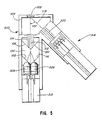
- FIG. 5 An example of a reflective instrument utilizing the optic 100 of the present invention is illustrated in FIG. 5.
- the reflective instrument is a reflectance readhead generally designated by the reference numeral 300.
- the reflectance readhead 300 is typically used to perform diffuse reflectance measurements on samples positioned adjacent a sample area aperture 302 defined in the housing 304 of the reflectance readhead 300.
- a common readhead geometry with multi-wavelength capability for diffuse reflectance is 45°/0°.
- a sample is illuminated at 45° with respect to the sample, and diffuse light is detected at 0°.
- Several illumination axes must be located radially around the 0° axis for the different light sources for each wavelength.
- the optic 100 of the present invention only one optical illumination axis is required. Consequently, space and cost requirements are reduced since only two optical axes are required, and all light sources are located in the same area.
- the readhead illumination axis can be located on the 0° axis, thus improving optical performance by illuminating normal to the sample surface.
- Light emitting diodes are commonly used as light sources in optical readheads that perform diffuse reflectance measurements. Each wavelength to be measured requires two light emitting diodes on independent optical axes where the light from both light emitting diodes illuminates the sample to be measured.
- the optic 100 By using the optic 100, one primary illumination optical axis along with two or more light emitting diodes at different wavelengths may be used in the reflectance readhead 300. This can be accomplished since the optic 100 combines several beams of light into one primary optical axis.
- the reflectance readhead 300 illustrated in FIG. 5 includes a first light source 306 and a second light source 308 that are held in a bundle by a light source holder 310.
- the light source bundle 310 may include more than the two light sources 306 and 308. Up to at least eight light sources mounted in a circular pattern in the housing 302 may be provided. For ease of illustration, however, only the two light sources 306 and 308 are illustrated.
- the light sources 306 and 308 provide two different wavelengths and are mounted side-by-side. For each light source 306 and 308, a corresponding pair of refractive surfaces such as surfaces 102 and 106 of optic 100 are provided. The outputs of the light sources 306 and 308 pass through the optic 100 which displaces the outputs into a common center axis or beam 312. The combined beam 312 passes through a first collimating tube 314 which functions to block stray light from reaching a sample positioned adjacent the sample area aperture 302. The collimating tube 314 also defines the proper sample illumination area.
- Diffuse light reflected from the sample is then detected by a detector amplifier generally designed by the reference numeral 316.
- Diffuse light 318 passes through a second collimating tube 320 which defines the detector viewing area and prevents stray light reflecting off the wall of the housing 304 surrounding the sample area aperture 302 from reaching the detector amplifier 316.
- the optic 100, the spectrometer 200, and the reflectance readhead 300 each uses two or more light sources of different wavelengths which share a common optical axis thereby eliminating the need for more than one independent detector.
- the optical design of the optic 100, the spectrometer 200 and the reflectance readhead 300 eliminate stray or noncollimated light generated by the light sources and associated optics.
- the optical design of the present invention requires no optical alignment during manufacturing.
Abstract
Description
- The device of the present invention generally relates to a new and improved optical transmission spectrometer for transmission measurements of scattering and absorbing samples, and more particularly, to a new and improved light beam-combiner for an optical transmission spectrometer, and a method for combining light beams from parallel sources in an optical transmission spectrometer.
- Optical transmission spectrometers are commonly used to read the amount of constituents in samples such as blood samples. Typically, these instruments cannot be used to make transmission measurements of scattering sample medium. Optical transmission spectrometers can include two sources of light arranged at 90° to each other. The two light sources are at different wavelengths. Performing measurements requires combining the two independent beams of light.
- The typical prior art optical transmission spectrometer includes an optic known as a beamsplitter for combining the beams of light. The optic is a translucent plate mounted in the spectrometer at 45° to the two incoming beams of light. In this position, the beamsplitter combines the first and second beams into a common beam directing this common beam through the specimen and onto a detector. Careful assembly of the spectrometer is required since the optic must be mounted at exactly 45° to the two beams of light. Thus, precise mounting of the light sources and the optic relative to the light sources is required. A small deviation in the mounting of any of these elements results in an inoperative or inaccurate spectrometer. The optic imposes a restriction on the spectrometer since the optic can only combine two light sources, thus limiting the utility of the spectrometer in the number of tests that can be performed.
- It is desirable to provide an optical transmission spectrometer that can use multiple light sources of different wavelengths allowing the instrument to conduct multiple tests on a single specimen. It is also desirable to provide a spectrometer that is small in size and uses parallel optical axes for the light sources rather than light source axes that are perpendicular to each other as in the prior art.
- An object of the present invention is to provide a new and improved optical transmission spectrometer for measuring constituents in a sample.
- Another object of the present invention is to provide a new and improved optical transmission spectrometer capable of conducting multiple tests on a single specimen.
- A further object of the present invention is to provide a new and improved optical transmission spectrometer including a plurality of parallel optical axes for the light sources each producing light at a different wavelength.
- A still further object of the present invention is to provide a new and improved optical transmission spectrometer including a plurality of light sources and an optic for combining the beams of light from the light sources along a common axis parallel to the axis of the original beams.
- Another object of the present invention is to provide a new and improved optical transmission spectrometer that can perform transmission measurements on scattering and absorbing related samples.
- Briefly, the present invention is directed to a new and improved instrument, commonly referred to as an optical transmission spectrometer, for measuring the absorption and scattering of light passing through a specimen, and thereby conducting one or more tests to measure constituents in the specimen.
- The spectrometer of the present invention includes a plurality of sources of light mounted parallel to each other. An optic or light beam-combiner is mounted in the spectrometer adjacent the sources of light. The beam-combiner includes a first refractive surface aligned at an angle of incidence of 45°, and a second refractive surface parallel to the first refractive surface. The first refractive surface refracts a first light beam toward a common or central axis of the optic. The second refractive surface refracts the beam along the common axis and parallel to its original path. Additional refractive surface perpendicular to the first and second refractive surfaces may be included on the beam-combiner for refracting additional beams of light.
- The beam-combiner is fabricated prior to mounting in the spectrometer. Since the critical dimensions and angles on the optic are fabricated prior to assembly of the spectrometer, the necessity for precise alignment of the beam-combiner with the light sources during assembly of the spectrometer is minimized.
- Since light passing through the optic is scattered and the sources of light inherently produce stray light, a first collimating tube is mounted in the spectrometer along the common axis and adjacent the beam-combiner to baffle this stray light and to transmit a primary beam to a sample area. A second collimating tube is mounted on the opposite side of the sample area from the first collimating tube to define the detector viewing area of the sample, and baffle stray light scattered by the sample and to transmit a primary beam to a detector mounted in the spectrometer. The detector measures the transmission of the primary beam and provides a reading in accordance with the particular test for which the spectrometer is being used.
- The above and other objects and advantages and novel features of the present invention will become apparent from the following detailed description of a preferred embodiment of the invention illustrated in the accompanying drawings wherein:
- FIG. 1 is a schematic illustration of a prior art beam-combiner or beamsplitter for combining the light beams of two sources of light oriented perpendicular to each other;
- FIG. 2 is a perspective view of a beam-combiner constructed in accordance with the principles of the present invention;
- FIG. 3 is a schematic illustration of the paths of light beams through the beam-combiner of the present invention;
- FIG. 4 is a vertical cross-sectional, reduced view of a optical transmission spectrometer including the beam-combiner of the present invention; and
- FIG. 5 is a cross-sectional, reduced plan view of a reflectance readhead including the beam-combiner of the present invention.
- Referring to the drawings and initially to FIG. 1, there is illustrated a prior art beamsplitter generally designated by the
reference numeral 10. Theprior art beamsplitter 10 is the traditional way to combine or split two independent, perpendicular beams of light from afirst light source 12 and asecond light source 14. Alight beam 16 from thefirst light source 12 is combined with a second light beam 18 from thesecond light source 14 by an optic 20 to produce a combined or single beam 22. - The optic 20 is a clear material that must be aligned precisely at 45° to the
incoming light beam 16 and the incoming light beam 18. The 90° orientation of thelight beams 16 and 18 and thelight sources - The 45° alignment of the optic 20 to
beams 16 and 18 necessitates each individual instrument to be assembled carefully and checked for proper alignment. Even after proper alignment of the optic 20, the instrument can become misaligned during usage requiring recalibration at the factory or point of manufacture. - Due to the alignment of optic 20 and the fact that it can be manufactured with only two surfaces, the number of light beams that can be combined using the optic 20 is limited. By limiting the number of light beams to two, the number of tests that each instrument can conduct is also limited.
- Referring now to FIGS. 2 and 3, optic 100 is capable of combining multiple light beams into a common or primary beam, and allows the sources of the light beams to be parallel to each other and closely aligned. This arrangement allows an instrument including the optic 100 to be made smaller and more portable.
- The optic 100 is fabricated from translucent material such as acrylic or polycarbonate with a first refractive or first surface to
air interface 102. Thefirst surface 102 is at an angle of incidence ϑ which is 45° measured relative to a central or common axis 104 (FIG. 2). A second refractive surface or second surface toair interface 106 is fabricated on the optic 100 and oriented parallel to the firstrefractive surface 102. The secondrefractive surface 106 is spaced from the firstrefractive surface 102 by the thickness t of the optic 100 measured perpendicularly to the firstrefractive surface 102 and the secondrefractive surface 106. - As a first
source light beam 108 hits the firstrefractive surface 102, part of that firstsource light beam 108 is reflected at a 45° angle to the firstrefractive surface 102 to define a firstreflected beam 110. Another component of the firstsource light beam 108 is refracted forming a first refractedlight beam 112 passing through the optic 100 and refracted toward the central orcommon axis 104. - As the first refracted
light beam 112 hits the secondrefractive surface 106, it is refracted parallel to theoriginal source beam 108. The first refracted source beam exiting the optic 100 is designated by the reference numeral 108A (FIG. 3). The first refracted source beam 108A is displaced a distance d from theoriginal source beam 108 by the optic 100. - In a similar fashion, a second
source light beam 114 hits a thirdrefractive surface 116 on the optic 100 forming a second refractedbeam 118 that passes through the optic 100 and is refracted toward thecommon axis 104. The thirdrefractive surface 116 is perpendicular to the firstrefractive surface 102 and is at a 45° angle to thecommon axis 104. The second refractedlight beam 118 after passing through the optic 100, hits a fourthrefractive surface 120. The fourthrefractive surface 120 is parallel to the thirdrefractive surface 116 and spaced from it by a distance equal to the thickness t. The fourthrefractive surface 120 is perpendicular to the secondrefractive surface 106. The second refractedlight beam 118 is refracted along thecommon axis 104 by the fourthrefractive surface 120 forming a second refracted source beam 114A which is parallel to the second sourcelight beam 114 and is displaced a distance d from the second sourcelight beam 114. The first refracted source light beam 108A and the second refracted source light beam 114A are spaced a sufficiently small distance apart such that they are in effect a single or primary beam of light extending along thecommon axis 104. This combined beam is designated by the reference numeral 122 (FIGS. 3 and 4). - The displacement d of the
light beams 
optic 100. For example, if the thickness of the optic 100 is .34 inch, which is standard for stock acrylic glass, and the index of reflection N of the acrylic glass is 1.491, and the angle of incidence is 45°; using the above formula the displacement d is calculated to be 0.1125 inch. - The optic 100 can be used in transmission or reflective instruments. An example of a transmission instrument is the optic transmission spectrometer generally designated by the
reference numeral 200 and illustrated in FIG. 4. Thespectrometer 200 can be used for both absorbing and scattering samples and has multi-wavelength capability allowing it to conduct multiple tests on a single specimen. - In the
spectrometer 200, the optic 100 is mounted in an optic andlight housing 202. Thehousing 202 and thus the optic 100 can be of any configuration such as square, rectangular or tubular. A preferred embodiment of the present invention is atubular housing 202 andoptic 100. Since the configuration of the optic 100 and thehousing 202 are substantially the same, assembly of thespectrometer 200 merely requires sliding theprefabricated optic 100 into thehousing 202 and rotating it to the correct position relative to thelight source bundle 203. If there is misalignment of thelight source bundle 203 relative to the optic 100, this misalignment is easily corrected by rotation of alight source holder 208 which mounts thelight source bundle 203 in thehousing 202. In contrast, in theprior art beamsplitter 10, precise location of thelight sources - Easy correction of misalignment allows the optic 100 to be manufactured separately from
spectrometer 200 and allows automated assembly since the alignment of the optic 100 is not as critical as in prior art beamsplitter. Thelight source bundle 203 includes several light sources such as a firstlight source 204 and a secondlight source 206 mounted in thehousing 202 adjacent theoptic 100. The light sources in thebundle 203 share a common optical axis eliminating the need for independent detectors. Although twolight sources light source bundle 203. For each light source, there are a pair of parallel reflective surfaces on theoptic 100. - Upon energization, the first
light source 204 generates and transmits the first sourcelight beam 108. The secondlight source 206, upon energization, generates and transmits the second sourcelight beam 114. Preferably, the firstlight source 204 and the secondlight source 206 are light emitting diodes (LED) of different wavelengths with highly collimated outputs. High collimation results in high optical throughput and lower stray light. LEDs of this type have flat reference surfaces providing accurate mechanical alignment. In a preferred embodiment, Siemens PN-GL 500 and IRL 500 LEDs are used. - The bundle of light sources including the first
light source 204 and the secondlight source 206 are held by thelight source holder 208 which is secured in the optic andlight housing 202. - Upon energization of the first
light source 204 and the secondlight source 206, the first sourcelight beam 108 and the second sourcelight beam 114 are refracted by theoptic 100. The resultant combinedprimary beam 122 passes into and through afirst collimating tube 210. Thefirst collimating tube 210 has baffles on the interior surface in the form of threads 212. The threads or baffles 212 function to baffle stray or scattered light and allow transmission of only theprimary beam 122 along collimatingtube 210. Theprimary beam 122 is transmitted to a read orsample area 214. - Typically, a sample holder or reaction vessel for performing analytical assays is positioned in the
read area 214. Theprimary beam 122 passes through the sample in the sample holder. A portion of theprimary beam 122 is absorbed by the different materials and reagents in the sample while other portions of theprimary beam 122 are reflected or scattered resulting in stray light. - After passing through the sample or specimen (not shown), the
primary beam 122 is detected by a detector assembly generally designated by thereference numeral 216. Thedetector assembly 216 includes adetector amplifier package 218 that detects and measures theprimary beam 122 after passage through the specimen. Thedetector amplifier package 218 is held by adetector holder 224, and the entiredetector amplifier package 218 is housed in ahousing 226. - The
primary beam 122, after passing through the sample (not shown), is transmitted to thedetector amplifier assembly 218 by asecond collimating tube 220. Thesecond collimating tube 220 includes baffles in the form ofinternal threads 222 which serve to baffle stray or scattered light resulting from scattering of theprimary beam 122 as it passes through the sample being measured. Thesecond collimating tube 220 serves to direct or transmit theprimary beam 122 to thedetector amplifier assembly 218. Thesecond collimating tube 220 also apertures the detector in thedetector amplifier assembly 218 at the proper distance from the sample defining the detector viewing area to that of theprimary beam 122. - The
spectrometer 200 employing the optic 100 can measure samples of both absorbing and scattering medium. The absorbing sample measurement measures the light absorbed by a colored liquid such as a colored sample in theread head 214. Typically, color is an indication of a constituent of the sample; for example, color in a blood sample would indicate the level of hemoglobin. - The
spectrometer 200 also measures scattering sample medium. For example, after reagents that are mixed in a blood sample have dissipated, there are latex beads remaining in the sample. These remaining beads tend to scatter light inprimary beam 122. The reading taken by thedetector amplifier assembly 218 in this condition of the sample is a scattering measurement. The amount of scattering is a measurement of the amount of reaction that took place in the blood sample and how much hemoglobin A1c there is in the sample. Thus, a scattering measurement not normally obtainable in prior art spectrometers can be obtained. - An example of a reflective instrument utilizing the
optic 100 of the present invention is illustrated in FIG. 5. The reflective instrument is a reflectance readhead generally designated by thereference numeral 300. Thereflectance readhead 300 is typically used to perform diffuse reflectance measurements on samples positioned adjacent asample area aperture 302 defined in thehousing 304 of thereflectance readhead 300. - Typically, a common readhead geometry with multi-wavelength capability for diffuse reflectance is 45°/0°. In this configuration a sample is illuminated at 45° with respect to the sample, and diffuse light is detected at 0°. Several illumination axes must be located radially around the 0° axis for the different light sources for each wavelength. By using the
optic 100 of the present invention, only one optical illumination axis is required. Consequently, space and cost requirements are reduced since only two optical axes are required, and all light sources are located in the same area. In addition, the readhead illumination axis can be located on the 0° axis, thus improving optical performance by illuminating normal to the sample surface. - Light emitting diodes are commonly used as light sources in optical readheads that perform diffuse reflectance measurements. Each wavelength to be measured requires two light emitting diodes on independent optical axes where the light from both light emitting diodes illuminates the sample to be measured. By using the optic 100, one primary illumination optical axis along with two or more light emitting diodes at different wavelengths may be used in the
reflectance readhead 300. This can be accomplished since the optic 100 combines several beams of light into one primary optical axis. - For example, the
reflectance readhead 300 illustrated in FIG. 5 includes a firstlight source 306 and a secondlight source 308 that are held in a bundle by alight source holder 310. As discussed with thespectrometer 200, thelight source bundle 310 may include more than the twolight sources housing 302 may be provided. For ease of illustration, however, only the twolight sources - The
light sources light source surfaces optic 100 are provided. The outputs of thelight sources beam 312. The combinedbeam 312 passes through afirst collimating tube 314 which functions to block stray light from reaching a sample positioned adjacent thesample area aperture 302. Thecollimating tube 314 also defines the proper sample illumination area. - Diffuse light reflected from the sample is then detected by a detector amplifier generally designed by the
reference numeral 316. Diffuse light 318 passes through asecond collimating tube 320 which defines the detector viewing area and prevents stray light reflecting off the wall of thehousing 304 surrounding thesample area aperture 302 from reaching thedetector amplifier 316. - The optic 100, the
spectrometer 200, and thereflectance readhead 300 each uses two or more light sources of different wavelengths which share a common optical axis thereby eliminating the need for more than one independent detector. In addition, the optical design of the optic 100, thespectrometer 200 and thereflectance readhead 300 eliminate stray or noncollimated light generated by the light sources and associated optics. Moreover, the optical design of the present invention requires no optical alignment during manufacturing.
Claims (10)
a body of optically clear material, said body having a central optical axis;
a first refractive surface on said body, said first refractive surface at a first angle of incidence relative to said central optical axis for refracting output from a first light source toward said central optical axis; and
a second refractive surface on said body parallel to said first refractive surface for refracting the output refracted by said first refractive surface along and parallel to said central optical axis.
a fourth refractive surface on said body for refracting the output refracted by said third refractive surface along and parallel to said central optical axis.

a first refractive surface on said optic for refracting a first parallel beam of light to produce a first refracted beam traveling through said optic toward a central axis of said optic;
a second refractive surface on said optic at approximately a right angle to said first refractive surface for refracting a second, parallel beam of light to produce a second refracted beam traveling through said optic toward said central axis of said optic;
a third refractive surface on said optic parallel to said first refractive surface for refracting said first refracted beam to a path parallel to and displaced from said first parallel beam of light; and
a fourth refractive surface on said optic parallel to aid second refractive surface for refracting said second refracted beam to a path combined with the path of said first refracted beam.
a plurality of light sources for producing light, the absorption of which in a sample is to be measured by the spectrometer;
a holder for said plurality of light sources;
a light beam-combiner for combining beams of light from said light sources by refraction into a primary beam of light, said light beam combiner including first and second parallel refractive surfaces for refracting light from said light sources into said primary beam;
a first collimating device adjacent said light beam-combiner for baffling stray light passing from the said light beam-combiner and the light source;
a mounting assembly for mounting a sample in the optical transmission spectrometer adjacent said first collimating device; and
a detection assembly for detecting absorption of light passing through a sample in said mounting assembly.
displacing a first light beam toward a common axis by refraction; and
after displacing said first light beam a predetermined distance, refracting said first light beam to a direction parallel with the common axis and said first light beam prior to refraction.
placing a first, translucent refractive surface in the path of said plurality of parallel light beams to refract and displace said plurality of light beams toward a common path; and
placing a second, translucent refractive surface parallel to and spaced by a predetermined distance from said first refractive surface to refract said refracted plurality of light beams along said common path.
Applications Claiming Priority (2)
| Application Number | Priority Date | Filing Date | Title |
|---|---|---|---|
| US07/267,309 US4930865A (en) | 1988-11-04 | 1988-11-04 | Optical transmission spectrometer |
| US267309 | 1988-11-04 |
Publications (3)
| Publication Number | Publication Date |
|---|---|
| EP0367097A2 true EP0367097A2 (en) | 1990-05-09 |
| EP0367097A3 EP0367097A3 (en) | 1991-09-11 |
| EP0367097B1 EP0367097B1 (en) | 1995-04-12 |
Family
ID=23018238
Family Applications (1)
| Application Number | Title | Priority Date | Filing Date |
|---|---|---|---|
| EP89119868A Expired - Lifetime EP0367097B1 (en) | 1988-11-04 | 1989-10-26 | Optical transmission spectrometer |
Country Status (5)
| Country | Link |
|---|---|
| US (1) | US4930865A (en) |
| EP (1) | EP0367097B1 (en) |
| JP (1) | JP2899651B2 (en) |
| CA (1) | CA1330494C (en) |
| DE (1) | DE68922181T2 (en) |
Cited By (5)
| Publication number | Priority date | Publication date | Assignee | Title |
|---|---|---|---|---|
| WO1994025849A1 (en) * | 1993-04-30 | 1994-11-10 | Jenoptik Gmbh | Device for the measurement of the reflectance at a point on a surface |
| US5429275A (en) * | 1991-07-02 | 1995-07-04 | Katz; Otto | Dispenser of doses of liquids and paste-like masses |
| WO2013167824A1 (en) * | 2012-05-09 | 2013-11-14 | Archimej Technology | Emission device for emitting a light beam of controlled spectrum |
| FR2990512A1 (en) * | 2012-05-09 | 2013-11-15 | Mejdi Nciri | Absorption spectrometer, has off-axis optical system including side chromatic aberration, and light sources placed at focal points of system corresponding to wavelengths, so that light beams of sources are multiplexed at exit of system |
| FR2990582A1 (en) * | 2012-11-20 | 2013-11-15 | Archimej Technology | Light emission device for emitting light beam of controlled spectrum in multispectral imaging apparatus, has optical assembly moving light beams spatially closer together, where light beams propagate in free space from LEDs to assembly |
Families Citing this family (13)
| Publication number | Priority date | Publication date | Assignee | Title |
|---|---|---|---|---|
| JPH079504B2 (en) * | 1990-04-25 | 1995-02-01 | 松下電器産業株式会社 | Bidirectional recognition head-up display device |
| CA2084923A1 (en) * | 1991-12-20 | 1993-06-21 | Ronald E. Stafford | Slm spectrometer |
| JPH05257081A (en) * | 1992-02-05 | 1993-10-08 | Nec Corp | Optical transmitter |
| JPH0749303A (en) * | 1993-04-01 | 1995-02-21 | High Yield Technol Inc | Particle sensor and particle detecting method |
| WO1996008710A1 (en) * | 1994-09-14 | 1996-03-21 | X-Rite Incorporated | Compact spectrophotometer |
| DE69533802T2 (en) * | 1994-09-14 | 2005-12-15 | X-Rite, Inc., Grandville | ABTASTKOLORIMETER |
| US6155489A (en) * | 1998-11-10 | 2000-12-05 | Ncr Corporation | Item checkout device including a bar code data collector and a produce data collector |
| US6332573B1 (en) | 1998-11-10 | 2001-12-25 | Ncr Corporation | Produce data collector and produce recognition system |
| US6431446B1 (en) | 1999-07-28 | 2002-08-13 | Ncr Corporation | Produce recognition system and method |
| US7173704B2 (en) * | 2003-02-26 | 2007-02-06 | Hamamatsu Photonics K.K. | Measuring device for immunochromatography test piece and light source device |
| US9335415B2 (en) * | 2012-10-31 | 2016-05-10 | The Boeing Company | Modulated laser range finder and method |
| JP6849404B2 (en) * | 2016-11-14 | 2021-03-24 | 浜松ホトニクス株式会社 | Spectral measuring device and spectroscopic measuring system |
| CN113695241B (en) * | 2021-08-30 | 2023-02-21 | 上海富驰高科技股份有限公司 | Full-inspection equipment for mobile phone lens support |
Citations (5)
| Publication number | Priority date | Publication date | Assignee | Title |
|---|---|---|---|---|
| US2098767A (en) * | 1935-03-18 | 1937-11-09 | William Jennings Bryan Jr | Double simultaneous motion picture apparatus |
| US2684010A (en) * | 1951-04-27 | 1954-07-20 | Standard Oil Co | Comparison candle colorimeter |
| US3856415A (en) * | 1972-04-28 | 1974-12-24 | Micromedic Systems Inc | Light shifting system for use in an optical instrument, such as a spectrophotometer |
| US3910701A (en) * | 1973-07-30 | 1975-10-07 | George R Henderson | Method and apparatus for measuring light reflectance absorption and or transmission |
| US4379233A (en) * | 1981-05-27 | 1983-04-05 | Trebor Industries, Inc. | Optical arrangement for quantitative analysis instrument utilizing pulsed radiation emitting diodes |
Family Cites Families (5)
| Publication number | Priority date | Publication date | Assignee | Title |
|---|---|---|---|---|
| GB435222A (en) * | 1933-08-25 | 1935-09-17 | Albert Joseph Arnulf | Apparatus for taking photographic or cinematographic views in colours |
| US2090398A (en) * | 1936-01-18 | 1937-08-17 | Telco System Inc | Stereo-refractor optical system |
| DE2934190A1 (en) * | 1979-08-23 | 1981-03-19 | Müller, Gerhard, Prof. Dr.-Ing., 7080 Aalen | METHOD AND DEVICE FOR MOLECULAR SPECTROSCOPY, ESPECIALLY FOR DETERMINING METABOLISM PRODUCTS |
| US4637717A (en) * | 1984-04-12 | 1987-01-20 | The United States Of America As Represented By The United States Department Of Energy | Dual beam translator for use in Laser Doppler anemometry |
| US4772094A (en) * | 1985-02-05 | 1988-09-20 | Bright And Morning Star | Optical stereoscopic system and prism window |
-
1988
- 1988-11-04 US US07/267,309 patent/US4930865A/en not_active Expired - Fee Related
-
1989
- 1989-09-28 CA CA000613832A patent/CA1330494C/en not_active Expired - Fee Related
- 1989-10-26 EP EP89119868A patent/EP0367097B1/en not_active Expired - Lifetime
- 1989-10-26 DE DE68922181T patent/DE68922181T2/en not_active Expired - Fee Related
- 1989-11-01 JP JP1283171A patent/JP2899651B2/en not_active Expired - Fee Related
Patent Citations (5)
| Publication number | Priority date | Publication date | Assignee | Title |
|---|---|---|---|---|
| US2098767A (en) * | 1935-03-18 | 1937-11-09 | William Jennings Bryan Jr | Double simultaneous motion picture apparatus |
| US2684010A (en) * | 1951-04-27 | 1954-07-20 | Standard Oil Co | Comparison candle colorimeter |
| US3856415A (en) * | 1972-04-28 | 1974-12-24 | Micromedic Systems Inc | Light shifting system for use in an optical instrument, such as a spectrophotometer |
| US3910701A (en) * | 1973-07-30 | 1975-10-07 | George R Henderson | Method and apparatus for measuring light reflectance absorption and or transmission |
| US4379233A (en) * | 1981-05-27 | 1983-04-05 | Trebor Industries, Inc. | Optical arrangement for quantitative analysis instrument utilizing pulsed radiation emitting diodes |
Non-Patent Citations (1)
| Title |
|---|
| MEDICAL PHYSICS, vol. 2, no. 4, July/August 1975, pages 219-220; M. GOITEIN: "Mechanism to facilitate the fine adjustment of sidelights" * |
Cited By (8)
| Publication number | Priority date | Publication date | Assignee | Title |
|---|---|---|---|---|
| US5429275A (en) * | 1991-07-02 | 1995-07-04 | Katz; Otto | Dispenser of doses of liquids and paste-like masses |
| WO1994025849A1 (en) * | 1993-04-30 | 1994-11-10 | Jenoptik Gmbh | Device for the measurement of the reflectance at a point on a surface |
| WO2013167824A1 (en) * | 2012-05-09 | 2013-11-14 | Archimej Technology | Emission device for emitting a light beam of controlled spectrum |
| FR2990512A1 (en) * | 2012-05-09 | 2013-11-15 | Mejdi Nciri | Absorption spectrometer, has off-axis optical system including side chromatic aberration, and light sources placed at focal points of system corresponding to wavelengths, so that light beams of sources are multiplexed at exit of system |
| FR2990524A1 (en) * | 2012-05-09 | 2013-11-15 | Archimej Technology | DEVICE FOR TRANSMITTING A CONTROLLED SPECTRUM LIGHT BEAM. |
| CN104380065A (en) * | 2012-05-09 | 2015-02-25 | 阿奇麦杰科技公司 | Emission device for emitting light beam of controlled spectrum |
| CN104380065B (en) * | 2012-05-09 | 2016-12-28 | 阿奇麦杰科技公司 | For launching the discharger of the light beam of controlled spectrum |
| FR2990582A1 (en) * | 2012-11-20 | 2013-11-15 | Archimej Technology | Light emission device for emitting light beam of controlled spectrum in multispectral imaging apparatus, has optical assembly moving light beams spatially closer together, where light beams propagate in free space from LEDs to assembly |
Also Published As
| Publication number | Publication date |
|---|---|
| CA1330494C (en) | 1994-07-05 |
| EP0367097B1 (en) | 1995-04-12 |
| JPH02173719A (en) | 1990-07-05 |
| DE68922181T2 (en) | 1995-08-24 |
| EP0367097A3 (en) | 1991-09-11 |
| US4930865A (en) | 1990-06-05 |
| JP2899651B2 (en) | 1999-06-02 |
| DE68922181D1 (en) | 1995-05-18 |
Similar Documents
| Publication | Publication Date | Title |
|---|---|---|
| EP0367097B1 (en) | Optical transmission spectrometer | |
| US5155628A (en) | Optical transmission spectrometer | |
| US4678326A (en) | Apparatus for the measurement of fluorescence, turbidity, luminescence or absorption | |
| US7414724B2 (en) | Light diffuser used in a testing apparatus | |
| US4886355A (en) | Combined gloss and color measuring instrument | |
| EP0102189B1 (en) | Reflectometer | |
| US4919535A (en) | Reflectance measuring apparatus for making contactless measurements | |
| US4379233A (en) | Optical arrangement for quantitative analysis instrument utilizing pulsed radiation emitting diodes | |
| EP0990135A1 (en) | Method and device for measuring reflected optical radiation | |
| CA2862447A1 (en) | Analyte monitor | |
| JPH07286957A (en) | Refractometer | |
| JP2012098282A (en) | System for performing scattering and absorption spectrometry | |
| FI78355C (en) | METHOD FOER MAETNING AV GLANS OCH APPARATUR FOER TILLAEMPNING AV METODEN. | |
| US11009457B2 (en) | Microplate reader | |
| US20020159050A1 (en) | Hand-held automatic refractometer | |
| CN112334756A (en) | Transmission device for examining samples in a cavity of a microtiter plate and method for examining samples in a cavity of a microtiter plate by means of transmission | |
| US20060076523A1 (en) | Light sensor, and detecting mechanism and light-measuring mechanism in analyzing device | |
| EP0903571A2 (en) | Apparatus and method for determining the concentration of specific substances | |
| GB2381579A (en) | Measuring instrument for determining the percentage of a component in a fluid | |
| JPH08159878A (en) | Illuminating and light receiving apparatus | |
| CN2141565Y (en) | Density sensor using optic fibre bundle | |
| SU1603196A1 (en) | Method and apparatus for photometric graduation of nephelometers | |
| CN106198398B (en) | Definition measuring device | |
| CN114216882A (en) | Material transmittance measuring method and material transmittance measuring device | |
| JP2008286530A (en) | Reflection characteristics measuring apparatus |
Legal Events
| Date | Code | Title | Description |
|---|---|---|---|
| PUAI | Public reference made under article 153(3) epc to a published international application that has entered the european phase |
Free format text: ORIGINAL CODE: 0009012 |
|
| 17P | Request for examination filed |
Effective date: 19891026 |
|
| AK | Designated contracting states |
Kind code of ref document: A2 Designated state(s): DE FR GB |
|
| PUAL | Search report despatched |
Free format text: ORIGINAL CODE: 0009013 |
|
| AK | Designated contracting states |
Kind code of ref document: A3 Designated state(s): DE FR GB |
|
| 17Q | First examination report despatched |
Effective date: 19930803 |
|
| GRAA | (expected) grant |
Free format text: ORIGINAL CODE: 0009210 |
|
| AK | Designated contracting states |
Kind code of ref document: B1 Designated state(s): DE FR GB |
|
| REF | Corresponds to: |
Ref document number: 68922181 Country of ref document: DE Date of ref document: 19950518 |
|
| ET | Fr: translation filed | ||
| PLBE | No opposition filed within time limit |
Free format text: ORIGINAL CODE: 0009261 |
|
| STAA | Information on the status of an ep patent application or granted ep patent |
Free format text: STATUS: NO OPPOSITION FILED WITHIN TIME LIMIT |
|
| 26N | No opposition filed | ||
| PGFP | Annual fee paid to national office [announced via postgrant information from national office to epo] |
Ref country code: FR Payment date: 19960913 Year of fee payment: 8 |
|
| PGFP | Annual fee paid to national office [announced via postgrant information from national office to epo] |
Ref country code: DE Payment date: 19960917 Year of fee payment: 8 |
|
| PGFP | Annual fee paid to national office [announced via postgrant information from national office to epo] |
Ref country code: GB Payment date: 19960925 Year of fee payment: 8 |
|
| PG25 | Lapsed in a contracting state [announced via postgrant information from national office to epo] |
Ref country code: GB Free format text: LAPSE BECAUSE OF NON-PAYMENT OF DUE FEES Effective date: 19971026 |
|
| PG25 | Lapsed in a contracting state [announced via postgrant information from national office to epo] |
Ref country code: FR Free format text: THE PATENT HAS BEEN ANNULLED BY A DECISION OF A NATIONAL AUTHORITY Effective date: 19971031 |
|
| GBPC | Gb: european patent ceased through non-payment of renewal fee |
Effective date: 19971026 |
|
| PG25 | Lapsed in a contracting state [announced via postgrant information from national office to epo] |
Ref country code: DE Free format text: LAPSE BECAUSE OF NON-PAYMENT OF DUE FEES Effective date: 19980701 |
|
| REG | Reference to a national code |
Ref country code: FR Ref legal event code: ST |