EP0365110A2 - Electrical connector assembly and method for connecting the same - Google Patents
Electrical connector assembly and method for connecting the same Download PDFInfo
- Publication number
- EP0365110A2 EP0365110A2 EP89306081A EP89306081A EP0365110A2 EP 0365110 A2 EP0365110 A2 EP 0365110A2 EP 89306081 A EP89306081 A EP 89306081A EP 89306081 A EP89306081 A EP 89306081A EP 0365110 A2 EP0365110 A2 EP 0365110A2
- Authority
- EP
- European Patent Office
- Prior art keywords
- bore
- externally threaded
- housing
- threaded portion
- coupling member
- Prior art date
- Legal status (The legal status is an assumption and is not a legal conclusion. Google has not performed a legal analysis and makes no representation as to the accuracy of the status listed.)
- Granted
Links
Images


Classifications
-
- H—ELECTRICITY
- H01—ELECTRIC ELEMENTS
- H01R—ELECTRICALLY-CONDUCTIVE CONNECTIONS; STRUCTURAL ASSOCIATIONS OF A PLURALITY OF MUTUALLY-INSULATED ELECTRICAL CONNECTING ELEMENTS; COUPLING DEVICES; CURRENT COLLECTORS
- H01R43/00—Apparatus or processes specially adapted for manufacturing, assembling, maintaining, or repairing of line connectors or current collectors or for joining electric conductors
-
- H—ELECTRICITY
- H01—ELECTRIC ELEMENTS
- H01R—ELECTRICALLY-CONDUCTIVE CONNECTIONS; STRUCTURAL ASSOCIATIONS OF A PLURALITY OF MUTUALLY-INSULATED ELECTRICAL CONNECTING ELEMENTS; COUPLING DEVICES; CURRENT COLLECTORS
- H01R13/00—Details of coupling devices of the kinds covered by groups H01R12/70 or H01R24/00 - H01R33/00
- H01R13/46—Bases; Cases
- H01R13/53—Bases or cases for heavy duty; Bases or cases for high voltage with means for preventing corona or arcing
-
- H—ELECTRICITY
- H01—ELECTRIC ELEMENTS
- H01R—ELECTRICALLY-CONDUCTIVE CONNECTIONS; STRUCTURAL ASSOCIATIONS OF A PLURALITY OF MUTUALLY-INSULATED ELECTRICAL CONNECTING ELEMENTS; COUPLING DEVICES; CURRENT COLLECTORS
- H01R4/00—Electrically-conductive connections between two or more conductive members in direct contact, i.e. touching one another; Means for effecting or maintaining such contact; Electrically-conductive connections having two or more spaced connecting locations for conductors and using contact members penetrating insulation
- H01R4/28—Clamped connections, spring connections
- H01R4/30—Clamped connections, spring connections utilising a screw or nut clamping member
-
- H—ELECTRICITY
- H01—ELECTRIC ELEMENTS
- H01R—ELECTRICALLY-CONDUCTIVE CONNECTIONS; STRUCTURAL ASSOCIATIONS OF A PLURALITY OF MUTUALLY-INSULATED ELECTRICAL CONNECTING ELEMENTS; COUPLING DEVICES; CURRENT COLLECTORS
- H01R4/00—Electrically-conductive connections between two or more conductive members in direct contact, i.e. touching one another; Means for effecting or maintaining such contact; Electrically-conductive connections having two or more spaced connecting locations for conductors and using contact members penetrating insulation
- H01R4/56—Electrically-conductive connections between two or more conductive members in direct contact, i.e. touching one another; Means for effecting or maintaining such contact; Electrically-conductive connections having two or more spaced connecting locations for conductors and using contact members penetrating insulation one conductor screwing into another
-
- Y—GENERAL TAGGING OF NEW TECHNOLOGICAL DEVELOPMENTS; GENERAL TAGGING OF CROSS-SECTIONAL TECHNOLOGIES SPANNING OVER SEVERAL SECTIONS OF THE IPC; TECHNICAL SUBJECTS COVERED BY FORMER USPC CROSS-REFERENCE ART COLLECTIONS [XRACs] AND DIGESTS
- Y10—TECHNICAL SUBJECTS COVERED BY FORMER USPC
- Y10S—TECHNICAL SUBJECTS COVERED BY FORMER USPC CROSS-REFERENCE ART COLLECTIONS [XRACs] AND DIGESTS
- Y10S439/00—Electrical connectors
- Y10S439/921—Transformer bushing type or high voltage underground connector
Definitions
- the invention relates to electrical connectors and, more particularly, to arrangements for connecting insulated, conductive members such as tap plugs and bushings. Still more particularly, the invention relates to bushing, cable connector and tap plug assemblies. The invention also relates to bushing wells and inserts and to feedthrough devices.
- the cable connector includes a housing having therein opposed, coaxial, tapered recesses, one of which receives a complementary tapered portion of the bushing and the other of which receives a complementary tapered portion of the tap plug.
- the cable connector assembly also includes a lug which is connected to the high-voltage cable, which extends between the recesses, and which is connected to the bushing and to the tap plug.
- the tap plug in one known construction (see, for example, U.S. Patent No. 4,354,721), the tap plug includes an externally threaded portion that threads into a bore in the lug and that has therethrough an axial bore, and the tap plug also includes an axially movable bolt which extends through the axial bore in the externally threaded portion and which threads into an internally threaded bore in the bushing.
- U.S. Patent No. 4,353,611 discloses a bushing well construction in which a bushing insert is connected to a bushing well by a threaded coupling member. A portion of the coupling member is threaded into the bushing well, and the bushing insert is threaded onto another portion of the coupling member.
- the invention provides an improved bushing, cable connector and tap plug assembly, and also provides a method and apparatus for connecting the cable connector and tap plug to the bushing.
- the assembly of the invention comprises a T-shaped cable connector including a housing defining opposed, coaxial, tapered recesses.
- the cable connector also includes a lug which is connected to a high-voltage cable and which extends into the housing between the recesses.
- the assembly also comprises a bushing adapted to be connected to an electrical apparatus such as a transformer.
- the bushing includes a tapered outer surface complementary with one of the recesses in the cable connector, and the bushing has therein an internally threaded bore.
- the assembly also comprises a loadbreak reducing tap plug.
- the tap plug includes an outer housing having a tapered outer surface complementary with the other recess in the cable connector.
- the tap plug also includes an externally threaded portion that extends from the tap plug housing and that is adapted to be threaded into an internally threaded bore in the cable connector lug.
- the tap plug also includes a contact assembly which is slideably housed within the tap plug housing and which is in electrical contact with a conductive surface within the tap plug.
- the tap plug also includes a "free-floating" nut rotatably housed within the tap plug housing and fixed against movement axially of the tap plug housing. In the preferred embodiment, the nut is fixed against axial movement by opposed shoulders or stops within the housing.
- the nut includes a socket adapted to receive a wrench for rotating the nut, and the nut has therein an internally threaded bore coaxial with a bore in the externally threaded portion.
- the assembly also includes a coupling member for facilitating threading of the externally threaded portion of the tap plug into the lug bore.
- the coupling member includes a first portion that is coaxial with the externally threaded portion of the tap plug and that has external threads substantially identical to and aligned with the threads on the externally threaded portion.
- the second portion of the coupling member is housed in the bore in the externally threaded portion and has therein socket means adapted to receive the tool.
- a shear pin extends between the externally threaded portion of the tap plug and the second portion of the coupling member for preventing rotation of the coupling member relative to the tap plug.
- the shear pin breaks when the coupling member is rotated and the torque exerted on the tap plug by the connector lug, which torque acts through the shear pin to resist rotation of the coupling member, reaches the desired level.
- the assembly also comprises a stud including an externally threaded first end adapted to be threaded into the nut, and an externally threaded second end adapted to be threaded into the bushing bore.
- the tap plug and cable connector are preferably connected to the bushing as follows. First, the second end of the stud is threaded into the bushing bore. Next, the wrench is used to thread the first portion of the coupling member and then the externally threaded portion of the tap plug into the lug bore. When the torque exerted on the tap plug by the cable connector lug reaches the desired level, the shear pin breaks and the coupling member is removed from the externally threaded portion of the tap plug and from the cable connector housing.
- the cable connector housing is placed over the bushing so that the first end of the stud extends into the bore in the externally threaded portion of the tap plug.
- the wrench is used to rotate the nut and thereby thread the nut onto the first end of the stud until the bushing engages the lug.
- the cable connector and tap plug are disconnected from the bushing by rotating the nut in the opposite direction. Since the externally threaded portion of the tap plug remains threaded into the lug and the nut is fixed against movement axially of the tap plug, rotation of the nut causes both the tap plug and the cable connector to back off the bushing and the stud.
- the invention also provides a bushing well insert and a feedthrough device utilizing the above-described free-floating unit.
- a principal feature of the invention is the provision of means for easily connecting a tap plug and a cable connector to a bushing. More particularly, the invention provides a connector system that is truly operable by a single operator. This is because, during connection, the threads of the nut and stud engage before interface interference is met. During disconnection, both the cable connector and tap plug are backed off the bushing because the nut is caged within the tap plug. This facilitates removal of the cable connector. Furthermore, the tap plug is retrofittable to existing copper and aluminum bushing rods, without any coordination for retrofitting.
- a tap plug comprising a housing, and a member which is rotatably supported by the housing, which is fixed against movement axially of the housing, and which includes means for threadedly engaging a bushing.
- the tap plug is preferably connected to a cable connector before the tap plug member is threadedly connected to the bushing. Because the member is fixed against movement in both directions axially of the housing, rotation of the member to engage the bushing causes both the tap plug and the cable connector to move onto the bushing. When the member is rotated to disengage the bushing, both the cable connector and the tap plug back off the bushing.
- Another principal feature of the invention is a method for connecting a cable connector and a tap plug to a bushing.
- Another principal feature of the invention is the provision of a coupling member for piloting the externally threaded portion of a tap plug into the internally threaded bore of a cable connector lug. This permits the operator to align the threads of the tap plug with the threads of the connector lug before the connector interferes with movement of the tap plug.
- frangible means e.g., a shear pin
- Another principal feature of the invention is a method utilizing the above-described coupling member for connecting a tap plug to a cable connector.
- Another principal feature of the invention is the provision of means for easily connecting either a bushing insert or a feedthrough device to a bushing well.
- the assembly 10 comprises a T-shaped cable connector 12.
- the cable connector 12 includes a T-shaped housing 14 defining opposed, coaxial, tapered recesses 16 and 18.
- the connector 12 also includes a lug or connector 20 which is connected to a high-voltage cable (not shown), which extends into the housing 14 between the recesses 16 and 18, and which has therethrough an internally threaded bore 22 coaxial with the recesses 16 and 18.
- the assembly 10 also comprises a bushing 24 which is adapted to be connected to an electrical apparatus (not shown) such as a transformer.
- the bushing 24 includes a tapered outer surface 26 complementary with the recess 16, and the bushing 24 has therein an internally threaded bore 28 that is coaxial with the bore 22 in the lug 20 when the bushing 24 is housed in the recess 16.
- the assembly 10 also comprises a loadbreak reducing tap plug 30.
- the tap plug 30 includes a housing 32 which has a tapered outer surface 34 complementary with the recess 18 and which has therein a bore 36 that is coaxial with the lug bore 22 when the tap plug 30 is housed in the recess 18.
- the tap plug 30 also includes an electrically conductive annular member or sleeve 38 housed in the bore 36 and having therethrough a bore 40, and an electrically conductive annular member or sleeve 42 which is housed in the bore 36, which is threadedly connected to the sleeve 38, which has therethrough a bore 44, and which has an externally threaded portion 46.
- the externally threaded portion 46 extends from the housing 32 and is adapted to be threaded into the lug bore 22.
- the tap plug 30 also includes a contact assembly 48 which is slideably housed within the bore 40 and which is in electrical contact with the inner surface of the sleeve 38.
- the tap plug 30 also includes a "free-floating" nut or member 50 rotatably housed within the bore 44.
- the nut 50 has therein an internally threaded bore 52 and includes socket means 54 adapted to receive a tool or wrench 56 (Fig. 2) for rotating the nut 50.
- the tap plug 30 also includes means for preventing movement of the nut 50 axially of the housing 32. In other words, the nut 50 is fixed against movement in both directions axially of the housing 32.
- this means includes, in the sleeve 42, a shoulder or stop 58 which prevents movement of the nut 50 to the left (as shown in Fig. 1) relative to the housing 32, and an annular member or ring 60 which is L-shaped in cross section, which is secured between the sleeves 38 and 42, and which provides, in the bore 44, a second shoulder or stop 62 that prevents movement of the nut 50 to the right (as shown in Fig. 1) relative to the housing 32.
- the stop 62 can be replaced by a stop on the sleeve 38.
- the assembly 10 also comprises means for facilitating threading of the externally threaded portion 46 into the lug bore 22, i.e., for aligning the threads of the externally threaded portion 46 with the threads of the lug bore 22.
- this means includes a coupling member 64 including first and second portions 66 and 68, respectively.
- the first portion 66 is coaxial with the externally threaded portion 46 and has external threads that are substantially identical to and aligned with the threads on the externally threaded portion 46.
- the first portion 66 of the coupling member 64 and the externally threaded portion 46 can be threaded into the lug bore 22.
- the second portion 68 of the coupling member 64 is housed in the bore 44 in the externally threaded portion 46 and has therein socket means 70 adapted to receive the tool 56.
- the facilitating means also includes frangible means for preventing rotation of the coupling member 64 relative to the tap plug 30.
- the frangible means breaks when the coupling member 64 is rotated and the torque exerted on the externally threaded portion 46 of the tap plug 30 by the lug 22, which torque acts through the frangible means to resist rotation of the coupling member 64, reaches the desired level. This prevents "over-torquing" of the tap plug 30 and consequent damage to the threads of either the tap plug 30 or the lug 20.
- the frangible means includes a shear pin 72 extending between the second portion 68 of the coupling member 64 and the externally threaded portion 46 of the tap plug 30.
- the assembly 10 also comprises a stud 74 including externally threaded first and second or right and left ends 76 and 78, respectively.
- the first end 76 of the stud 74 is adapted to be threaded into the nut 50, and the second end 78 of the stud 74 is adapted to be threaded into the bushing bore 28.
- Figs. 2-8 The preferred method for connecting the tap plug 30 to the cable connector 12, and then the cable connector 12 to the bushing 24 is illustrated in Figs. 2-8.
- the externally threaded portion 46 of the tap plug 30 is turned or threaded into the lug bore 22 as shown in Figs. 4-7.
- the wrench or tool 56 to rotate the coupling member 64 and the tap plug 30, the first portion 66 of the coupling member 64 is threaded into the lug 20, as shown in Fig. 5.
- Continued rotation of the coupling member 64 causes the externally threaded portion 46 of the tap plug 30 to be threaded into the lug 20, as shown in Fig. 6.
- the second end 78 of the stud 74 is threaded into the bushing bore 28.
- the cable connector housing 14 is placed over the bushing 24 so that the first end 76 of the stud 74 extends into the bore 44 in the externally threaded portion 46 of the tap plug 30, as shown in Fig. 8.
- the wrench 56 is used to rotate the nut 50 and thereby thread the nut 50 onto the first end 76 of the stud 74, as shown in Fig. 2. Because the nut 50 is fixed axially of the tap plug 30, threading of the nut 50 onto the stud 74 causes both the tap plug 30 and the cable connector 12 to move toward the bushing 24, until the lug 20 engages the bushing 24.
- the externally threaded portion 46 of the tap plug 30 can be threaded into the lug 20 without the assistance of the coupling member 64, although this can be difficult to do.
- the cable connector 12 and tap plug 30 are disconnected from the bushing 24 by rotating the nut 50 in the opposite direction. Since the externally threaded portion 46 of the tap plug 30 remains threaded into the lug 20 and the nut 50 is fixed against movement axially of the tap plug 30, rotation of the nut 50 causes both the tap plug 30 and the cable connector 12 to back off the bushing 24 and the stud 74.
- FIG. 9 An alternative tap plug 80 is illustrated in Fig. 9.
- the alternative tap plug 80 is similar in many respects to the tap plug 30 of the preferred embodiment, and common elements have been given the same reference numerals.
- the tap plug 80 includes a bolt 82 rotatably supported within the bore 44.
- the bolt 82 includes a head 84 rotatably housed in the bore 44, and an externally threaded portion 86 that extends outwardly of the externally threaded portion 46 of the tap plug 80.
- the head 84 is fixed against movement axially of the housing 32 by the ring 60 and by a bushing or sleeve 88 which is housed in the bore 44 and which engages the head 84 to prevent movement of the head 84 to the left as shown in Fig. 9.
- the head 84 includes socket means 90 adapted to receive the wrench 56.
- the tap plug 80 is connected to the cable connector 12 by threading the externally threaded portion 46 of the tap plug 80 into the lug 20.
- the bolt 82 is rotated with the wrench 56 to thread the bolt 82 into the bushing bore 22 and to thereby connect the tap plug 80 and cable connector 12 to the bushing 24.
- the cable connector 12 and tap plug 80 are disconnected from the bushing 24 by rotating the bolt 82 in the opposite direction. Because the bolt 82 is fixed axially of the tap plug 80, this causes both the tap plug 80 and the connector 12 to back off the bushing 24.
- the invention can also be embodied in an assembly including a tap plug, a bushing and a connecting sleeve, i.e., a device which is similar to the cable connector 12 but which only connects a tap plug to a bushing and does not include a connection to a cable.
- the invention can also be embodied in an assembly including a tap plug, a cable connector and a dead-end plug (instead of the bushing 24), or in an assembly including just a tap plug and a cable connector.
- the assembly 100 includes a bushing well 102, and a bushing well insert 104.
- the bushing well 102 is conventional and includes a well member 106 which has therein a recess 108, and a contact element 110 which is secured within the well member 106 and which has an externally threaded end 112.
- the insert 104 includes a housing 114 having therein a bore 116 and having a tapered outer surface 118 complementary with the recess 108 in the well member 106.
- the insert 104 also includes a contact assembly 120, and a conductive annular member or sleeve 122 housed in the bore 116.
- the insert 104 further includes braided wire 124 electrically connecting the sleeve 122 and the contact assembly 120 and permitting axial movement of the contact assembly 120 relative to the sleeve 122.
- the insert 104 also includes a free-floating nut 126 rotatably housed within the sleeve 122.
- the nut 126 has therein an internally threaded bore 128 and includes socket means 130 adapted to receive a tool or wrench (not shown) for rotating the nut 126.
- the insert 104 also includes means for preventing movement of the nut 126 axially of the housing 114.
- this means includes an annular groove 132 in the inner surface of the sleeve 122, an annular groove 134 in the outer surface of the nut 126, the grooves 132 and 134 being aligned, and an annular member 136 which extends into both grooves 132 and 134 to prevent relative axial movement of the nut 126 and the sleeve 122 and to permit relative rotation of the nut 126 and the sleeve 122.
- the insert 104 and bushing well 102 are connected as follows. First, the insert 104 is inserted into the recess 108 in the bushing well 102 until the contact 110 engages the nut 126. Next, the wrench is used to rotate the nut 126 and thereby thread the nut 126 onto the contact 110. Preferably, the wrench includes a depth gauge that insures that the insert 104 is fully inserted into the bushing well 102. Because the nut 126 is fixed axially of the insert 104, threading of the nut 126 onto the contact 110 causes the insert 104 to move toward the contact 110 and thus into the bushing well 102 until the contact 110 engages the sleeve 122. Since the nut 126 is rotated relative to the insert housing 114, there is no rotation of the insert housing 114 relative to the bushing well 102. Thus, it is not necessary to turn the insert 104 against the well 102.
- the insert 104 and well 102 are disconnected by rotating the nut 126 in the opposite direction. Since the nut 126 is fixed against movement axially of the insert 104, rotation of the nut 126 causes the insert 104 to back off the bushing well 102.
- a feedthrough device 150 that is a second alternative embodiment of the invention is illustrated in Fig. 11.
- the feedthrough device 150 includes elements which are substantially identical to elements of the insert 104 and which have been given the same reference numerals.
- the main difference between the corresponding elements of the feedthrough device 150 and the insert 104 is that the nut 126 has a greater axial length.
- the feedthrough device 150 is adapted to be connected to a bushing well such as the bushing well 102 shown in Fig. 10.
- the feedthrough device 150 can be placed in any rotational position relative to the bushing well 102. The feedthrough device 150 is simply placed in the desired position and then the nut 126 is threaded onto the contact 110 of the bushing well 102.
Abstract
Description
- The invention relates to electrical connectors and, more particularly, to arrangements for connecting insulated, conductive members such as tap plugs and bushings. Still more particularly, the invention relates to bushing, cable connector and tap plug assemblies. The invention also relates to bushing wells and inserts and to feedthrough devices.
- It is known to use a T-shaped cable connector to connect a high-voltage cable and a tap plug to a bushing on an electrical apparatus. Typically, the cable connector includes a housing having therein opposed, coaxial, tapered recesses, one of which receives a complementary tapered portion of the bushing and the other of which receives a complementary tapered portion of the tap plug. The cable connector assembly also includes a lug which is connected to the high-voltage cable, which extends between the recesses, and which is connected to the bushing and to the tap plug.
- In one known construction (see, for example, U.S. Patent No. 4,354,721), the tap plug includes an externally threaded portion that threads into a bore in the lug and that has therethrough an axial bore, and the tap plug also includes an axially movable bolt which extends through the axial bore in the externally threaded portion and which threads into an internally threaded bore in the bushing.
- Additionally, U.S. Patent No. 4,353,611 discloses a bushing well construction in which a bushing insert is connected to a bushing well by a threaded coupling member. A portion of the coupling member is threaded into the bushing well, and the bushing insert is threaded onto another portion of the coupling member.
- The invention provides an improved bushing, cable connector and tap plug assembly, and also provides a method and apparatus for connecting the cable connector and tap plug to the bushing.
- The assembly of the invention comprises a T-shaped cable connector including a housing defining opposed, coaxial, tapered recesses. The cable connector also includes a lug which is connected to a high-voltage cable and which extends into the housing between the recesses. The assembly also comprises a bushing adapted to be connected to an electrical apparatus such as a transformer. The bushing includes a tapered outer surface complementary with one of the recesses in the cable connector, and the bushing has therein an internally threaded bore.
- The assembly also comprises a loadbreak reducing tap plug. The tap plug includes an outer housing having a tapered outer surface complementary with the other recess in the cable connector. The tap plug also includes an externally threaded portion that extends from the tap plug housing and that is adapted to be threaded into an internally threaded bore in the cable connector lug.
- The tap plug also includes a contact assembly which is slideably housed within the tap plug housing and which is in electrical contact with a conductive surface within the tap plug. The tap plug also includes a "free-floating" nut rotatably housed within the tap plug housing and fixed against movement axially of the tap plug housing. In the preferred embodiment, the nut is fixed against axial movement by opposed shoulders or stops within the housing. The nut includes a socket adapted to receive a wrench for rotating the nut, and the nut has therein an internally threaded bore coaxial with a bore in the externally threaded portion.
- The assembly also includes a coupling member for facilitating threading of the externally threaded portion of the tap plug into the lug bore. The coupling member includes a first portion that is coaxial with the externally threaded portion of the tap plug and that has external threads substantially identical to and aligned with the threads on the externally threaded portion. The second portion of the coupling member is housed in the bore in the externally threaded portion and has therein socket means adapted to receive the tool. A shear pin extends between the externally threaded portion of the tap plug and the second portion of the coupling member for preventing rotation of the coupling member relative to the tap plug. Preferably, the shear pin breaks when the coupling member is rotated and the torque exerted on the tap plug by the connector lug, which torque acts through the shear pin to resist rotation of the coupling member, reaches the desired level.
- The assembly also comprises a stud including an externally threaded first end adapted to be threaded into the nut, and an externally threaded second end adapted to be threaded into the bushing bore.
- The tap plug and cable connector are preferably connected to the bushing as follows. First, the second end of the stud is threaded into the bushing bore. Next, the wrench is used to thread the first portion of the coupling member and then the externally threaded portion of the tap plug into the lug bore. When the torque exerted on the tap plug by the cable connector lug reaches the desired level, the shear pin breaks and the coupling member is removed from the externally threaded portion of the tap plug and from the cable connector housing.
- Next, the cable connector housing is placed over the bushing so that the first end of the stud extends into the bore in the externally threaded portion of the tap plug. Next, the wrench is used to rotate the nut and thereby thread the nut onto the first end of the stud until the bushing engages the lug.
- The cable connector and tap plug are disconnected from the bushing by rotating the nut in the opposite direction. Since the externally threaded portion of the tap plug remains threaded into the lug and the nut is fixed against movement axially of the tap plug, rotation of the nut causes both the tap plug and the cable connector to back off the bushing and the stud.
- The invention also provides a bushing well insert and a feedthrough device utilizing the above-described free-floating unit.
- A principal feature of the invention is the provision of means for easily connecting a tap plug and a cable connector to a bushing. More particularly, the invention provides a connector system that is truly operable by a single operator. This is because, during connection, the threads of the nut and stud engage before interface interference is met. During disconnection, both the cable connector and tap plug are backed off the bushing because the nut is caged within the tap plug. This facilitates removal of the cable connector. Furthermore, the tap plug is retrofittable to existing copper and aluminum bushing rods, without any coordination for retrofitting.
- Another principal feature of the invention is the provision of a tap plug comprising a housing, and a member which is rotatably supported by the housing, which is fixed against movement axially of the housing, and which includes means for threadedly engaging a bushing. The tap plug is preferably connected to a cable connector before the tap plug member is threadedly connected to the bushing. Because the member is fixed against movement in both directions axially of the housing, rotation of the member to engage the bushing causes both the tap plug and the cable connector to move onto the bushing. When the member is rotated to disengage the bushing, both the cable connector and the tap plug back off the bushing.
- Another principal feature of the invention is a method for connecting a cable connector and a tap plug to a bushing.
- Another principal feature of the invention is the provision of a coupling member for piloting the externally threaded portion of a tap plug into the internally threaded bore of a cable connector lug. This permits the operator to align the threads of the tap plug with the threads of the connector lug before the connector interferes with movement of the tap plug.
- Another principal feature of the invention is the provision of frangible means, e.g., a shear pin, connecting the coupling member to the tap plug in order to obtain proper torquing of the tap plug into the connector lug.
- Another principal feature of the invention is a method utilizing the above-described coupling member for connecting a tap plug to a cable connector.
- Another principal feature of the invention is the provision of means for easily connecting either a bushing insert or a feedthrough device to a bushing well.
- In the accompanying drawings:-
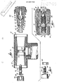
- Fig. 1 is an exploded elevational view, partially in section, of a bushing, cable connector and tap plug assembly embodying the invention and comprising a bushing, a stud, a cable connector, a tap plug, and a coupling member.
- Fig. 2 is an enlarged view, partially in section, of the assembly with the tap plug and cable connector connected to the bushing.
- Fig. 3 is a partial view of the bushing, stud and cable connector with the stud threaded into the bushing.
- Figs. 4-7 sequentially illustrate a method for threading the tap plug into the cable connector.
- Fig. 8 is a view similar to Fig. 3 with the tap plug threaded into the cable connector.
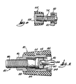
- Fig. 9 is an elevational view, partially in section, of an alternative construction of the tap plug.
- Fig. 10 is a view, partially in section, of a bushing well and insert assembly embodying the invention.
- Fig. 11 is a view, partially in section, of a feedthrough device embodying the invention.
- Before one embodiment of the invention is explained in detail, it is to be understood that the invention is not limited in its application to the details of construction and the arrangements of components set forth in the following description or illustrated in the drawings. The invention is capable of other embodiments and of being practiced or being carried out in various ways. Also, it is to be understood that the phraseology and terminology used herein is for the purpose of description and should not be regarded as limiting.
- An
assembly 10 embodying the invention is illustrated in the drawings. As shown in Fig. 1, theassembly 10 comprises a T-shapedcable connector 12. Thecable connector 12 includes a T-shapedhousing 14 defining opposed, coaxial, taperedrecesses connector 12 also includes a lug orconnector 20 which is connected to a high-voltage cable (not shown), which extends into thehousing 14 between therecesses recesses - The
assembly 10 also comprises abushing 24 which is adapted to be connected to an electrical apparatus (not shown) such as a transformer. Thebushing 24 includes a taperedouter surface 26 complementary with therecess 16, and thebushing 24 has therein an internally threaded bore 28 that is coaxial with thebore 22 in thelug 20 when thebushing 24 is housed in therecess 16. - The
assembly 10 also comprises a loadbreak reducingtap plug 30. The tap plug 30 includes ahousing 32 which has a taperedouter surface 34 complementary with therecess 18 and which has therein abore 36 that is coaxial with the lug bore 22 when thetap plug 30 is housed in therecess 18. The tap plug 30 also includes an electrically conductive annular member orsleeve 38 housed in thebore 36 and having therethrough abore 40, and an electrically conductive annular member orsleeve 42 which is housed in thebore 36, which is threadedly connected to thesleeve 38, which has therethrough abore 44, and which has an externally threadedportion 46. The externally threadedportion 46 extends from thehousing 32 and is adapted to be threaded into the lug bore 22. - The tap plug 30 also includes a contact assembly 48 which is slideably housed within the
bore 40 and which is in electrical contact with the inner surface of thesleeve 38. The tap plug 30 also includes a "free-floating" nut ormember 50 rotatably housed within thebore 44. Thenut 50 has therein an internally threaded bore 52 and includes socket means 54 adapted to receive a tool or wrench 56 (Fig. 2) for rotating thenut 50. The tap plug 30 also includes means for preventing movement of thenut 50 axially of thehousing 32. In other words, thenut 50 is fixed against movement in both directions axially of thehousing 32. While various suitable means can be employed, in the preferred embodiment this means includes, in thesleeve 42, a shoulder or stop 58 which prevents movement of thenut 50 to the left (as shown in Fig. 1) relative to thehousing 32, and an annular member orring 60 which is L-shaped in cross section, which is secured between thesleeves bore 44, a second shoulder or stop 62 that prevents movement of thenut 50 to the right (as shown in Fig. 1) relative to thehousing 32. In alternative embodiments (not shown), thestop 62 can be replaced by a stop on thesleeve 38. - The
assembly 10 also comprises means for facilitating threading of the externally threadedportion 46 into the lug bore 22, i.e., for aligning the threads of the externally threadedportion 46 with the threads of the lug bore 22. While various suitable means can be used, in the illustrated construction, this means includes acoupling member 64 including first andsecond portions first portion 66 is coaxial with the externally threadedportion 46 and has external threads that are substantially identical to and aligned with the threads on the externally threadedportion 46. Thus, thefirst portion 66 of thecoupling member 64 and the externally threadedportion 46 can be threaded into the lug bore 22. Thesecond portion 68 of thecoupling member 64 is housed in thebore 44 in the externally threadedportion 46 and has therein socket means 70 adapted to receive thetool 56. The facilitating means also includes frangible means for preventing rotation of thecoupling member 64 relative to thetap plug 30. In the preferred embodiment, the frangible means breaks when thecoupling member 64 is rotated and the torque exerted on the externally threadedportion 46 of thetap plug 30 by thelug 22, which torque acts through the frangible means to resist rotation of thecoupling member 64, reaches the desired level. This prevents "over-torquing" of thetap plug 30 and consequent damage to the threads of either thetap plug 30 or thelug 20. This also prevents "under-torquing" of thetap plug 30 and thus prevents a connection that is too loose. Preferably, the frangible means includes ashear pin 72 extending between thesecond portion 68 of thecoupling member 64 and the externally threadedportion 46 of thetap plug 30. - The
assembly 10 also comprises astud 74 including externally threaded first and second or right and left ends 76 and 78, respectively. Thefirst end 76 of thestud 74 is adapted to be threaded into thenut 50, and thesecond end 78 of thestud 74 is adapted to be threaded into the bushing bore 28. - The preferred method for connecting the
tap plug 30 to thecable connector 12, and then thecable connector 12 to thebushing 24 is illustrated in Figs. 2-8. First, the externally threadedportion 46 of thetap plug 30 is turned or threaded into the lug bore 22 as shown in Figs. 4-7. Using the wrench ortool 56 to rotate thecoupling member 64 and thetap plug 30, thefirst portion 66 of thecoupling member 64 is threaded into thelug 20, as shown in Fig. 5. Continued rotation of thecoupling member 64 causes the externally threadedportion 46 of thetap plug 30 to be threaded into thelug 20, as shown in Fig. 6. Eventually, the torque exerted on thetap plug 30 by thecable connector lug 20 reaches the desired level and theshear pin 72 breaks, as shown in Fig. 7. Thecoupling member 64 is then removed from the externally threadedportion 46 of thetap plug 30 and from thecable connector housing 14. - Either before or after the above-described steps, the
second end 78 of thestud 74 is threaded into the bushing bore 28. After thestud 74 is threaded into thebushing 24 and the externally threadedportion 46 is threaded into thelug 20, thecable connector housing 14 is placed over thebushing 24 so that thefirst end 76 of thestud 74 extends into thebore 44 in the externally threadedportion 46 of thetap plug 30, as shown in Fig. 8. Next, thewrench 56 is used to rotate thenut 50 and thereby thread thenut 50 onto thefirst end 76 of thestud 74, as shown in Fig. 2. Because thenut 50 is fixed axially of thetap plug 30, threading of thenut 50 onto thestud 74 causes both thetap plug 30 and thecable connector 12 to move toward thebushing 24, until thelug 20 engages thebushing 24. - Alternatively, the externally threaded
portion 46 of thetap plug 30 can be threaded into thelug 20 without the assistance of thecoupling member 64, although this can be difficult to do. - The
cable connector 12 and tap plug 30 are disconnected from thebushing 24 by rotating thenut 50 in the opposite direction. Since the externally threadedportion 46 of thetap plug 30 remains threaded into thelug 20 and thenut 50 is fixed against movement axially of thetap plug 30, rotation of thenut 50 causes both thetap plug 30 and thecable connector 12 to back off thebushing 24 and thestud 74. - An
alternative tap plug 80 is illustrated in Fig. 9. Thealternative tap plug 80 is similar in many respects to thetap plug 30 of the preferred embodiment, and common elements have been given the same reference numerals. - Instead of the
nut 50 of the preferred embodiment, thetap plug 80 includes abolt 82 rotatably supported within thebore 44. Thebolt 82 includes ahead 84 rotatably housed in thebore 44, and an externally threadedportion 86 that extends outwardly of the externally threadedportion 46 of thetap plug 80. Thehead 84 is fixed against movement axially of thehousing 32 by thering 60 and by a bushing orsleeve 88 which is housed in thebore 44 and which engages thehead 84 to prevent movement of thehead 84 to the left as shown in Fig. 9. Thehead 84 includes socket means 90 adapted to receive thewrench 56. - The tap plug 80 is connected to the
cable connector 12 by threading the externally threadedportion 46 of thetap plug 80 into thelug 20. Next, thebolt 82 is rotated with thewrench 56 to thread thebolt 82 into the bushing bore 22 and to thereby connect thetap plug 80 andcable connector 12 to thebushing 24. Thecable connector 12 and tap plug 80 are disconnected from thebushing 24 by rotating thebolt 82 in the opposite direction. Because thebolt 82 is fixed axially of thetap plug 80, this causes both thetap plug 80 and theconnector 12 to back off thebushing 24. - It should be understood that while the preferred embodiment of the invention is a tap plug, cable connector and bushing assembly, the invention can also be embodied in an assembly including a tap plug, a bushing and a connecting sleeve, i.e., a device which is similar to the
cable connector 12 but which only connects a tap plug to a bushing and does not include a connection to a cable. The invention can also be embodied in an assembly including a tap plug, a cable connector and a dead-end plug (instead of the bushing 24), or in an assembly including just a tap plug and a cable connector. - An
assembly 100 which is an alternative embodiment of the invention is illustrated in Fig. 10. Theassembly 100 includes a bushing well 102, and a bushing well insert 104. - The bushing well 102 is conventional and includes a
well member 106 which has therein a recess 108, and acontact element 110 which is secured within thewell member 106 and which has an externally threadedend 112. - The
insert 104 includes ahousing 114 having therein abore 116 and having a taperedouter surface 118 complementary with the recess 108 in thewell member 106. Theinsert 104 also includes acontact assembly 120, and a conductive annular member orsleeve 122 housed in thebore 116. Theinsert 104 further includes braidedwire 124 electrically connecting thesleeve 122 and thecontact assembly 120 and permitting axial movement of thecontact assembly 120 relative to thesleeve 122. - The
insert 104 also includes a free-floatingnut 126 rotatably housed within thesleeve 122. Thenut 126 has therein an internally threadedbore 128 and includes socket means 130 adapted to receive a tool or wrench (not shown) for rotating thenut 126. Theinsert 104 also includes means for preventing movement of thenut 126 axially of thehousing 114. While various suitable means can be employed, in the illustrated construction, this means includes an annular groove 132 in the inner surface of thesleeve 122, anannular groove 134 in the outer surface of thenut 126, thegrooves 132 and 134 being aligned, and anannular member 136 which extends into bothgrooves 132 and 134 to prevent relative axial movement of thenut 126 and thesleeve 122 and to permit relative rotation of thenut 126 and thesleeve 122. - The
insert 104 and bushing well 102 are connected as follows. First, theinsert 104 is inserted into the recess 108 in the bushing well 102 until thecontact 110 engages thenut 126. Next, the wrench is used to rotate thenut 126 and thereby thread thenut 126 onto thecontact 110. Preferably, the wrench includes a depth gauge that insures that theinsert 104 is fully inserted into the bushing well 102. Because thenut 126 is fixed axially of theinsert 104, threading of thenut 126 onto thecontact 110 causes theinsert 104 to move toward thecontact 110 and thus into the bushing well 102 until thecontact 110 engages thesleeve 122. Since thenut 126 is rotated relative to theinsert housing 114, there is no rotation of theinsert housing 114 relative to the bushing well 102. Thus, it is not necessary to turn theinsert 104 against thewell 102. - The
insert 104 and well 102 are disconnected by rotating thenut 126 in the opposite direction. Since thenut 126 is fixed against movement axially of theinsert 104, rotation of thenut 126 causes theinsert 104 to back off the bushing well 102. - A
feedthrough device 150 that is a second alternative embodiment of the invention is illustrated in Fig. 11. Thefeedthrough device 150 includes elements which are substantially identical to elements of theinsert 104 and which have been given the same reference numerals. The main difference between the corresponding elements of thefeedthrough device 150 and theinsert 104 is that thenut 126 has a greater axial length. Like theinsert 104, thefeedthrough device 150 is adapted to be connected to a bushing well such as the bushing well 102 shown in Fig. 10. - Because the
nut 126, rather than theentire feedthrough device 150, is threaded onto thecontact 110 of the bushing well 102, thefeedthrough device 150 can be placed in any rotational position relative to the bushing well 102. Thefeedthrough device 150 is simply placed in the desired position and then thenut 126 is threaded onto thecontact 110 of the bushing well 102.
Claims (19)
a housing, and
a first member which is rotatably supported by said housing, which is fixed against movement in both directions axially of said housing, and which includes means for threadedly engaging the conductive member.
providing a connector having therethrough an internally threaded first bore, a first member having therein an internally threaded second bore, a second insulated, conductive member including a housing, an externally threaded portion extending from said housing and having therein a third bore, and a nut which includes an internally threaded fourth bore aligned with said third bore and which is rotatably supported by said housing, and a stud having externally threaded first and second ends,
threading said first end of said stud into said second bore,
threading said externally threaded portion of said second member into said first bore,
and
threading said second end of said stud into said fourth bore.
a first insulated, conductive member adapted to be connected to a connector having therein an internally threaded first bore, said first member including an externally threaded portion which is adapted to be threaded into the first bore and which has therein a second bore, and
a coupling member including a first portion which is coaxial with said externally threaded portion of said first member, which is externally threaded and which is adapted to be threaded into the first bore, and a second portion housed in said second bore.
providing a connector having therein an internally threaded first bore, a first insulated, conductive member including an externally threaded portion which is adapted to be threaded into said first bore and which has therein a second bore, and a coupling member including a first portion which is coaxial with said externally threaded portion of said first member, which is externally threaded, and which is adapted to be threaded into said first bore, and a second portion housed in said second bore,
threading said first portion of said coupling member into said first bore until said externally threaded portion of said first member is aligned with said first bore, and
rotating said coupling member to thread said externally threaded portion of said first member into said first bore.
a connector having therethrough an internally threaded first bore,
a first member, and
a second insulated, conductive member including a housing, an externally threaded portion threaded into said first bore, and a third member which is rotatably supported by said housing, which is fixed against movement in both directions axially of said housing, and which includes means for threadedly engaging said first member.
Priority Applications (1)
| Application Number | Priority Date | Filing Date | Title |
|---|---|---|---|
| EP94203362A EP0649189B1 (en) | 1988-10-17 | 1989-06-15 | Electrical connector assembly and method for connecting the same |
Applications Claiming Priority (2)
| Application Number | Priority Date | Filing Date | Title |
|---|---|---|---|
| US258619 | 1988-10-17 | ||
| US07/258,619 US4857021A (en) | 1988-10-17 | 1988-10-17 | Electrical connector assembly and method for connecting the same |
Related Child Applications (2)
| Application Number | Title | Priority Date | Filing Date |
|---|---|---|---|
| EP94203362A Division EP0649189B1 (en) | 1988-10-17 | 1989-06-15 | Electrical connector assembly and method for connecting the same |
| EP94203362.2 Division-Into | 1989-06-15 |
Publications (3)
| Publication Number | Publication Date |
|---|---|
| EP0365110A2 true EP0365110A2 (en) | 1990-04-25 |
| EP0365110A3 EP0365110A3 (en) | 1991-02-27 |
| EP0365110B1 EP0365110B1 (en) | 1996-03-06 |
Family
ID=22981388
Family Applications (2)
| Application Number | Title | Priority Date | Filing Date |
|---|---|---|---|
| EP89306081A Expired - Lifetime EP0365110B1 (en) | 1988-10-17 | 1989-06-15 | Electrical connector assembly and method for connecting the same |
| EP94203362A Expired - Lifetime EP0649189B1 (en) | 1988-10-17 | 1989-06-15 | Electrical connector assembly and method for connecting the same |
Family Applications After (1)
| Application Number | Title | Priority Date | Filing Date |
|---|---|---|---|
| EP94203362A Expired - Lifetime EP0649189B1 (en) | 1988-10-17 | 1989-06-15 | Electrical connector assembly and method for connecting the same |
Country Status (7)
| Country | Link |
|---|---|
| US (1) | US4857021A (en) |
| EP (2) | EP0365110B1 (en) |
| JP (1) | JP2863555B2 (en) |
| KR (1) | KR0157402B1 (en) |
| BR (1) | BR8903890A (en) |
| CA (1) | CA1306293C (en) |
| DE (2) | DE68925859D1 (en) |
Families Citing this family (49)
| Publication number | Priority date | Publication date | Assignee | Title |
|---|---|---|---|---|
| US5041004A (en) * | 1990-02-13 | 1991-08-20 | Cooper Power Systems, Inc. | Electrical connector with means for limiting the torque applied during threaded engagement |
| US5421750A (en) * | 1994-05-24 | 1995-06-06 | Amerace Corporation | 200 AMP bolted elbow with a loadbreak tap |
| JP3042579B2 (en) * | 1994-07-22 | 2000-05-15 | 矢崎総業株式会社 | Screw structure of distribution box |
| US6042407A (en) * | 1998-04-23 | 2000-03-28 | Hubbell Incorporated | Safe-operating load reducing tap plug and method using the same |
| US6364216B1 (en) * | 2001-02-20 | 2002-04-02 | G&W Electric Co. | Universal power connector for joining flexible cables to rigid devices in any of many configurations |
| US6416338B1 (en) * | 2001-03-13 | 2002-07-09 | Hubbell Incorporated | Electrical connector with dual action piston |
| US6520795B1 (en) | 2001-08-02 | 2003-02-18 | Hubbell Incorporated | Load reducing electrical device |
| US6744255B1 (en) | 2002-10-30 | 2004-06-01 | Mcgraw -Edison Company | Grounding device for electric power distribution systems |
| US7413455B2 (en) * | 2005-01-14 | 2008-08-19 | Cooper Technologies Company | Electrical connector assembly |
| US7381103B2 (en) * | 2005-04-01 | 2008-06-03 | Richards Manufacturing Company | Multiple bore termination system having an integrally formed component |
| DE202005005297U1 (en) * | 2005-04-04 | 2006-08-10 | Cooper Crouse-Hinds Gmbh | Cable bushing device |
| US7491075B2 (en) | 2005-07-28 | 2009-02-17 | Cooper Technologies Company | Electrical connector |
| US7341468B2 (en) | 2005-07-29 | 2008-03-11 | Cooper Technologies Company | Separable loadbreak connector and system with shock absorbent fault closure stop |
| US7572133B2 (en) | 2005-11-14 | 2009-08-11 | Cooper Technologies Company | Separable loadbreak connector and system |
| US7494355B2 (en) | 2007-02-20 | 2009-02-24 | Cooper Technologies Company | Thermoplastic interface and shield assembly for separable insulated connector system |
| US7854620B2 (en) | 2007-02-20 | 2010-12-21 | Cooper Technologies Company | Shield housing for a separable connector |
| US7950939B2 (en) | 2007-02-22 | 2011-05-31 | Cooper Technologies Company | Medium voltage separable insulated energized break connector |
| US7666012B2 (en) | 2007-03-20 | 2010-02-23 | Cooper Technologies Company | Separable loadbreak connector for making or breaking an energized connection in a power distribution network |
| US7568927B2 (en) * | 2007-04-23 | 2009-08-04 | Cooper Technologies Company | Separable insulated connector system |
| US7633741B2 (en) | 2007-04-23 | 2009-12-15 | Cooper Technologies Company | Switchgear bus support system and method |
| US7661979B2 (en) | 2007-06-01 | 2010-02-16 | Cooper Technologies Company | Jacket sleeve with grippable tabs for a cable connector |
| TW200910705A (en) * | 2007-07-09 | 2009-03-01 | Thomas & Betts Internationnal Inc | Bushing well with improved coupling components |
| US7695291B2 (en) | 2007-10-31 | 2010-04-13 | Cooper Technologies Company | Fully insulated fuse test and ground device |
| US7578682B1 (en) | 2008-02-25 | 2009-08-25 | Cooper Technologies Company | Dual interface separable insulated connector with overmolded faraday cage |
| US7950940B2 (en) | 2008-02-25 | 2011-05-31 | Cooper Technologies Company | Separable connector with reduced surface contact |
| US8056226B2 (en) | 2008-02-25 | 2011-11-15 | Cooper Technologies Company | Method of manufacturing a dual interface separable insulated connector with overmolded faraday cage |
| US7905735B2 (en) | 2008-02-25 | 2011-03-15 | Cooper Technologies Company | Push-then-pull operation of a separable connector system |
| US7670162B2 (en) | 2008-02-25 | 2010-03-02 | Cooper Technologies Company | Separable connector with interface undercut |
| US8109776B2 (en) | 2008-02-27 | 2012-02-07 | Cooper Technologies Company | Two-material separable insulated connector |
| US7811113B2 (en) | 2008-03-12 | 2010-10-12 | Cooper Technologies Company | Electrical connector with fault closure lockout |
| US7878849B2 (en) | 2008-04-11 | 2011-02-01 | Cooper Technologies Company | Extender for a separable insulated connector |
| US7958631B2 (en) | 2008-04-11 | 2011-06-14 | Cooper Technologies Company | Method of using an extender for a separable insulated connector |
| US8602800B2 (en) * | 2010-04-20 | 2013-12-10 | Thomas & Betts International, Inc. | Electrical connector having alignment mechanism |
| US8641434B2 (en) | 2010-07-21 | 2014-02-04 | Thomas & Betts International, Inc | Rotatable feedthru insert |
| DE102010046410B3 (en) * | 2010-09-23 | 2012-02-16 | Spinner Gmbh | Electrical connector with a union nut |
| CN102610936A (en) * | 2012-04-06 | 2012-07-25 | 山东电力集团公司枣庄供电公司 | Conductor joint |
| CN103618157A (en) * | 2013-11-30 | 2014-03-05 | 国家电网公司 | Electrical equipment ground lead connecting device |
| MX363765B (en) * | 2014-04-07 | 2019-04-02 | S & C Electric Co | Replaceable bushing for electrical equipment. |
| US9385493B2 (en) * | 2014-04-10 | 2016-07-05 | S&C Electric Company | Adjustable bus bar for power distribution equipment |
| AU2015203548B2 (en) * | 2014-06-26 | 2016-05-12 | Thomas & Betts International, Llc | Elbow with internal assembly system |
| EP3128617A1 (en) * | 2015-08-04 | 2017-02-08 | Dubuis et Cie | Device for fixing an electrical connection terminal to a support |
| US10756452B2 (en) * | 2017-11-30 | 2020-08-25 | Hubbell Incorporated | Electrical connector with shearable fastener |
| DE102017223811B4 (en) * | 2017-12-27 | 2021-05-27 | Tyco Electronics Raychem Gmbh | Coupling bolts for high-current plugs |
| US10460886B2 (en) * | 2018-01-26 | 2019-10-29 | Robert K. Jones | Single phase underground fused tap |
| CN110048287A (en) * | 2019-02-28 | 2019-07-23 | 中车洛阳机车有限公司 | A kind of connection method of locomotive high-voltage cable connector |
| KR102597247B1 (en) * | 2019-06-04 | 2023-11-03 | 한국전력공사 | Inspecting apparatus for connecting status of connector |
| TW202207555A (en) * | 2020-06-30 | 2022-02-16 | 美商Ppc寬頻股份有限公司 | Adapters for connecting a connector to a cable tap |
| SE544606C2 (en) * | 2021-01-20 | 2022-09-20 | Saab Ab | High Voltage Adapter |
| WO2022226006A1 (en) * | 2021-04-22 | 2022-10-27 | Hubbell Incorporated | Tap plugs |
Citations (5)
| Publication number | Priority date | Publication date | Assignee | Title |
|---|---|---|---|---|
| US2967289A (en) * | 1959-06-29 | 1961-01-03 | Day Chauncey Castle | Connector means |
| US4354721A (en) * | 1980-12-31 | 1982-10-19 | Amerace Corporation | Attachment arrangement for high voltage electrical connector |
| US4722694A (en) * | 1986-12-01 | 1988-02-02 | Rte Corporation | High voltage cable connector |
| US4773872A (en) * | 1987-05-11 | 1988-09-27 | Amerace Corporation | Static contact member for a high-voltage bushing insert |
| DE3709942A1 (en) * | 1987-03-26 | 1988-10-06 | Rheydt Kabelwerk Ag | T-shaped cable fitting |
Family Cites Families (6)
| Publication number | Priority date | Publication date | Assignee | Title |
|---|---|---|---|---|
| US3982812A (en) * | 1973-10-01 | 1976-09-28 | General Electric Company | Power cable separable connector having gasket means for restricting the flow of arc-generated gases therefrom |
| US3883208A (en) * | 1973-10-25 | 1975-05-13 | Rte Corp | Visible break tee-connector |
| US4202591A (en) * | 1978-10-10 | 1980-05-13 | Amerace Corporation | Apparatus for the remote grounding, connection and disconnection of high voltage electrical circuits |
| US4353611A (en) * | 1980-03-06 | 1982-10-12 | Amerace Corporation | Bushing well stud construction |
| US4420202A (en) * | 1981-09-10 | 1983-12-13 | Pemco Corporation | Plural phase cable couplers |
| FR2585516B1 (en) * | 1985-07-25 | 1988-03-18 | Legrand Sa | SIDE CONNECTION BLOCK |
-
1988
- 1988-10-17 US US07/258,619 patent/US4857021A/en not_active Expired - Lifetime
-
1989
- 1989-06-14 CA CA000602834A patent/CA1306293C/en not_active Expired - Lifetime
- 1989-06-15 EP EP89306081A patent/EP0365110B1/en not_active Expired - Lifetime
- 1989-06-15 DE DE68925859T patent/DE68925859D1/en not_active Expired - Lifetime
- 1989-06-15 DE DE68928792T patent/DE68928792D1/en not_active Expired - Lifetime
- 1989-06-15 EP EP94203362A patent/EP0649189B1/en not_active Expired - Lifetime
- 1989-07-28 JP JP1196436A patent/JP2863555B2/en not_active Expired - Lifetime
- 1989-08-02 BR BR898903890A patent/BR8903890A/en not_active IP Right Cessation
- 1989-08-22 KR KR1019890011914A patent/KR0157402B1/en not_active IP Right Cessation
Patent Citations (5)
| Publication number | Priority date | Publication date | Assignee | Title |
|---|---|---|---|---|
| US2967289A (en) * | 1959-06-29 | 1961-01-03 | Day Chauncey Castle | Connector means |
| US4354721A (en) * | 1980-12-31 | 1982-10-19 | Amerace Corporation | Attachment arrangement for high voltage electrical connector |
| US4722694A (en) * | 1986-12-01 | 1988-02-02 | Rte Corporation | High voltage cable connector |
| DE3709942A1 (en) * | 1987-03-26 | 1988-10-06 | Rheydt Kabelwerk Ag | T-shaped cable fitting |
| US4773872A (en) * | 1987-05-11 | 1988-09-27 | Amerace Corporation | Static contact member for a high-voltage bushing insert |
Also Published As
| Publication number | Publication date |
|---|---|
| CA1306293C (en) | 1992-08-11 |
| EP0365110B1 (en) | 1996-03-06 |
| EP0649189A3 (en) | 1995-09-13 |
| EP0649189A2 (en) | 1995-04-19 |
| US4857021A (en) | 1989-08-15 |
| JPH02129871A (en) | 1990-05-17 |
| EP0365110A3 (en) | 1991-02-27 |
| KR900007142A (en) | 1990-05-09 |
| BR8903890A (en) | 1990-04-17 |
| DE68925859D1 (en) | 1996-04-11 |
| DE68928792D1 (en) | 1998-09-24 |
| EP0649189B1 (en) | 1998-08-19 |
| KR0157402B1 (en) | 1998-11-16 |
| JP2863555B2 (en) | 1999-03-03 |
Similar Documents
| Publication | Publication Date | Title |
|---|---|---|
| EP0365110B1 (en) | Electrical connector assembly and method for connecting the same | |
| US4779341A (en) | Method of using a tap plug installation tool | |
| US6520795B1 (en) | Load reducing electrical device | |
| US4354721A (en) | Attachment arrangement for high voltage electrical connector | |
| US4715104A (en) | Installation tool | |
| EP0270473B1 (en) | High voltage cable connector | |
| CA2056226C (en) | Improved high voltage elbow | |
| EP0449737B1 (en) | Electrical connector | |
| US4799895A (en) | 600-Amp hot stick operable screw-assembled connector system | |
| CA2022949C (en) | 600-amp hot stick-operable screw and pin-and-socket assembled connector system | |
| EP3430687B1 (en) | Connector and cable with torque-limiting features | |
| JPS6350820B2 (en) | ||
| EP0147979A1 (en) | High voltage connector | |
| EP2688153A2 (en) | Electrical connector having grounding mechanism | |
| US4874327A (en) | Universal cable head for a multiconductor logging cable | |
| US4360967A (en) | Assembly tool for electrical connectors | |
| JPS5835012B2 (en) | Remote grounding device for high voltage electrical circuits | |
| US4776089A (en) | Method of assembling tap plug to cable connector | |
| EP0092616B1 (en) | Attachment arrangement for high voltage electrical connector | |
| US20200358222A1 (en) | Deadbreak connector | |
| CA1177129A (en) | Attachment arrangement for high voltage electrical connector | |
| EP0092615B1 (en) | Assembly tool for electrical connectors | |
| JPS6355752B2 (en) | ||
| CA1179488A (en) | Assembly tool for electrical connectors | |
| JPS58201279A (en) | Assembling tool for electric connector |
Legal Events
| Date | Code | Title | Description |
|---|---|---|---|
| PUAI | Public reference made under article 153(3) epc to a published international application that has entered the european phase |
Free format text: ORIGINAL CODE: 0009012 |
|
| AK | Designated contracting states |
Kind code of ref document: A2 Designated state(s): CH DE FR GB LI SE |
|
| PUAL | Search report despatched |
Free format text: ORIGINAL CODE: 0009013 |
|
| AK | Designated contracting states |
Kind code of ref document: A3 Designated state(s): CH DE FR GB LI SE |
|
| 17P | Request for examination filed |
Effective date: 19910823 |
|
| 17Q | First examination report despatched |
Effective date: 19931207 |
|
| GRAA | (expected) grant |
Free format text: ORIGINAL CODE: 0009210 |
|
| AK | Designated contracting states |
Kind code of ref document: B1 Designated state(s): CH DE FR GB LI SE |
|
| PG25 | Lapsed in a contracting state [announced via postgrant information from national office to epo] |
Ref country code: LI Effective date: 19960306 Ref country code: FR Effective date: 19960306 Ref country code: CH Effective date: 19960306 |
|
| XX | Miscellaneous (additional remarks) |
Free format text: TEILANMELDUNG 94203362.2 EINGEREICHT AM 15/06/89. |
|
| REF | Corresponds to: |
Ref document number: 68925859 Country of ref document: DE Date of ref document: 19960411 |
|
| PG25 | Lapsed in a contracting state [announced via postgrant information from national office to epo] |
Ref country code: SE Effective date: 19960606 |
|
| PG25 | Lapsed in a contracting state [announced via postgrant information from national office to epo] |
Ref country code: DE Effective date: 19960608 |
|
| EN | Fr: translation not filed | ||
| REG | Reference to a national code |
Ref country code: CH Ref legal event code: PL |
|
| PLBE | No opposition filed within time limit |
Free format text: ORIGINAL CODE: 0009261 |
|
| STAA | Information on the status of an ep patent application or granted ep patent |
Free format text: STATUS: NO OPPOSITION FILED WITHIN TIME LIMIT |
|
| 26N | No opposition filed | ||
| REG | Reference to a national code |
Ref country code: GB Ref legal event code: IF02 |
|
| PGFP | Annual fee paid to national office [announced via postgrant information from national office to epo] |
Ref country code: GB Payment date: 20080506 Year of fee payment: 20 |
|
| REG | Reference to a national code |
Ref country code: GB Ref legal event code: PE20 Expiry date: 20090614 |
|
| PG25 | Lapsed in a contracting state [announced via postgrant information from national office to epo] |
Ref country code: GB Free format text: LAPSE BECAUSE OF EXPIRATION OF PROTECTION Effective date: 20090614 |