EP0359596A1 - Data transmission installation to facilitate and accelerate the manufacture of spectacle glasses - Google Patents
Data transmission installation to facilitate and accelerate the manufacture of spectacle glasses Download PDFInfo
- Publication number
- EP0359596A1 EP0359596A1 EP89401912A EP89401912A EP0359596A1 EP 0359596 A1 EP0359596 A1 EP 0359596A1 EP 89401912 A EP89401912 A EP 89401912A EP 89401912 A EP89401912 A EP 89401912A EP 0359596 A1 EP0359596 A1 EP 0359596A1
- Authority
- EP
- European Patent Office
- Prior art keywords
- card
- bus
- data
- connector
- microprocessor
- Prior art date
- Legal status (The legal status is an assumption and is not a legal conclusion. Google has not performed a legal analysis and makes no representation as to the accuracy of the status listed.)
- Withdrawn
Links
Images

Classifications
-
- G—PHYSICS
- G05—CONTROLLING; REGULATING
- G05B—CONTROL OR REGULATING SYSTEMS IN GENERAL; FUNCTIONAL ELEMENTS OF SUCH SYSTEMS; MONITORING OR TESTING ARRANGEMENTS FOR SUCH SYSTEMS OR ELEMENTS
- G05B19/00—Programme-control systems
- G05B19/02—Programme-control systems electric
- G05B19/418—Total factory control, i.e. centrally controlling a plurality of machines, e.g. direct or distributed numerical control [DNC], flexible manufacturing systems [FMS], integrated manufacturing systems [IMS], computer integrated manufacturing [CIM]
- G05B19/41845—Total factory control, i.e. centrally controlling a plurality of machines, e.g. direct or distributed numerical control [DNC], flexible manufacturing systems [FMS], integrated manufacturing systems [IMS], computer integrated manufacturing [CIM] characterised by system universality, reconfigurability, modularity
-
- G—PHYSICS
- G05—CONTROLLING; REGULATING
- G05B—CONTROL OR REGULATING SYSTEMS IN GENERAL; FUNCTIONAL ELEMENTS OF SUCH SYSTEMS; MONITORING OR TESTING ARRANGEMENTS FOR SUCH SYSTEMS OR ELEMENTS
- G05B19/00—Programme-control systems
- G05B19/02—Programme-control systems electric
- G05B19/418—Total factory control, i.e. centrally controlling a plurality of machines, e.g. direct or distributed numerical control [DNC], flexible manufacturing systems [FMS], integrated manufacturing systems [IMS], computer integrated manufacturing [CIM]
- G05B19/4185—Total factory control, i.e. centrally controlling a plurality of machines, e.g. direct or distributed numerical control [DNC], flexible manufacturing systems [FMS], integrated manufacturing systems [IMS], computer integrated manufacturing [CIM] characterised by the network communication
-
- Y—GENERAL TAGGING OF NEW TECHNOLOGICAL DEVELOPMENTS; GENERAL TAGGING OF CROSS-SECTIONAL TECHNOLOGIES SPANNING OVER SEVERAL SECTIONS OF THE IPC; TECHNICAL SUBJECTS COVERED BY FORMER USPC CROSS-REFERENCE ART COLLECTIONS [XRACs] AND DIGESTS
- Y02—TECHNOLOGIES OR APPLICATIONS FOR MITIGATION OR ADAPTATION AGAINST CLIMATE CHANGE
- Y02P—CLIMATE CHANGE MITIGATION TECHNOLOGIES IN THE PRODUCTION OR PROCESSING OF GOODS
- Y02P90/00—Enabling technologies with a potential contribution to greenhouse gas [GHG] emissions mitigation
- Y02P90/02—Total factory control, e.g. smart factories, flexible manufacturing systems [FMS] or integrated manufacturing systems [IMS]
Definitions
- the present invention relates generally to the machining of ophthalmic lenses and more particularly to an installation intended to facilitate and accelerate the supply of finished spectacles to users.
- the latter when a customer has chosen a frame from an optician, the latter must first measure the position of the client's pupils relative to the chosen frame and then, if he has the appropriate lenses in stock, center them on the frame according to the identified position of the pupils, and finally cut them out in a grinding machine, if it has one.
- the optician does not have the glasses in stock, which is the most frequent case, he must order them from a supplier and if in addition he does not have a grinding machine he must transmit to the supplier all the measures necessary for cut the lenses and center them and mount them properly on the frame.
- the object of the invention is to provide an installation having a great flexibility of operation and making it possible to considerably speed up the supply of the finished glasses by eliminating almost any risk. errors.
- FR-2,582,975 in the name of the applicant describes an apparatus comprising electronic means and which makes it possible to integrate the measurements of the deviation and the height of the pupils, previously taken for example by means of the apparatus described in FR- A-2.620.927 by the applicant, to center the glass blanks on the frames by calculating the grinding dimensions and to center and place an adapter on the blank.
- This device associated with a copious of frames is marketed under the brand "SCANFORM" and is able to directly order a grinder.
- the invention aims to produce an installation comprising a working set to which an optician can directly address and associating Scanform devices and grinders with a data transmission network.
- a computer is connected to said module forming a master assembly, itself connected by a point-to-point data transmission line and bidirectional to said slave modules.
- said first and the other devices for centering blanks and for fitting adapters are of the type described in FR-2,582,975.
- said first set is a device marketed by the applicant under the brand "Scanform”.
- an optician can either send to said installation, by post or otherwise, a handwritten note comprising the data necessary for the identification of the chosen frame, at the height and away from the pupils, and to the prescription corrective lenses, or send the same data via a telephone data transmission line if it has one, for example connected to a personal management computer, as is more and more common.
- the data is entered manually into the module forming the master assembly by an operator who uses this assembly to perform the centering operations, one of the slave groups receiving the dimensions calculated by said assembly and consequently controlling its associated grinder.
- the orders and the data which are part of them are received and managed by said computer and transmitted one after the other to the module forming the master assembly, and the operator performs the remaining necessary operations.
- each of the master / slave modules contains a first electronic card by carrying out the piloting and the control and to which are connected a second electronic card forming communication and archiving processor and a third electronic card regulating the supply of electrical energy to the entire module.
- the second card forming a communication and archiving processor contains an internal bus connecting a microprocessor controlling the exchanges between the first card and the external systems, to different electronic signal / data processing circuits, via a bus interface carrying out the adaptation and demultiplexing of the microprocessor signals, and a synchronization interface connecting the microprocessor to the first card.
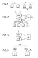
- FIG. 1 which shows the general arrangement of an installation in accordance with the invention
- the latter essentially comprises a master apparatus or module A forming a master assembly (which is unique and is imperatively provided), apparatuses or slave modules B1, B2, ... (multiple and optional, also designated below in the text generally by the reference B), and a computer C (single and optional).
- the devices B are connected to the device A by a data transmission channel R with multipoint structures, while the devices A and C are connected by a data transmission channel L with point-to-point structure.
- the devices A and B have the same architecture, as shown in more detail in FIG. 2, their operation being differentiated by means of particular electrical signals present in the line R connecting the various devices A and B to the network.
- the devices A and B are made up of different mechanical elements which, depending on the specificity of the use of the device, are present in part or in whole, as can be seen in FIG. 2, these different elements are: an input mechanism S, making it possible to read the internal shape of a spectacle frame and transform it into a series of electrical signals S1; a mechanism V for viewing this shape and for depositing a suction cup for gripping a raw glass according to a specific coded geometric reference as well as the shape by means of a series of electrical signals S2, a mechanism which includes a keyboard with keys allowing the optician to give orders or translated information subsequently in electrical signals and associated with the other signals S2; a mechanism M for grinding the raw glass, making it possible to give the latter a profile identical to the shape described, by means of electrical signals S3.
- an input mechanism S making it possible to read the internal shape of a spectacle frame and transform it into a series of electrical signals S1
- a mechanism V for viewing this shape and for depositing a suction cup for gripping a raw glass according
- This AUT card is itself connected to a second electronic COM card, called the communication and archiving processor, by means of an electrical signal transmission channel S4, and it is on this card that the R and L channels for data transmission.
- the assembly is completed by a third electronic card ALI, called the power supply card, which makes it possible to supply the electrical energies Ui necessary for the other sub-assemblies from the sector.
- ALI the power supply card
- the installation according to the invention makes it possible to transmit between the various devices for opticians all their service data and all the data specific to each patient and necessary for the work carried out on these appliances.
- the link is controlled by only one of these devices which is the logical master of the link between all the devices and ensures the link with the management microcomputer and ensures the management of the archives.
- a computer can be connected directly to the network, in which case control can then be attributed to another device.
- the devices are connected to a serial, multipoint and bidirectional transmission line, operated in half-duplex.
- the master appliance A may not include mechanisms such as those described above, its architecture then being reduced to that shown in FIG. 3.
- the AUT PLC card can even be replaced by a simple computer having its own storage, processing and calculation devices, and possibly operator dialogs. In the case of this configuration, it will be noted that the device C is then deleted.
- the device C is a computer having its own storage, processing, calculation and operator dialogue devices (keyboard and CRT for example), and is also connected by an interface to channel L of data transmission.
- the combination of these devices A, B, C automates all the operations of an optician in his pharmacy or in a laboratory, from the reception of a patient with the taking into account of his prescription until on the issue of a pair of fitted glasses.
- Figure 4 represents the card forming the COM communications processor, which is the basis of the specific operation of the device A for the intended treatment.
- This card provides the communication protocol in the installation as well as the management of files and is generally carried out by the so-called HC MOS technology.
- This card includes various connectors for connection with external elements and internal circuits.
- Connector 1 transmits according to a transmission bidirectional a set of signals arriving from the bidirectional signal transmission channel R.
- the connector 2 transmits a set of electrical signals, comprising levels conforming to recommendation V24 of the CCITT Committee, establishes bidirectional links for transmission of electrical signals, having the levels conforming to recommendation V24 / V28 of the CCITT Committee, and is connected to device C, which is a computer or, as we will see later, is possibly a modem.
- the connector 3 joins the COM card to the AUT card in a bidirectional connection, for the transmission of signals previously designated by S4.
- the connector 4 delivers the energy necessary for the operation of the COM card receiving supply signals Ui coming from the ALI card.
- the COM card includes a microprocessor 5 (for example of the type known under the acronym 80C88, namely of the 16-bit type with data transmission bus with 8 bits)
- This microprocessor is connected in particular to a backup memory CMOS RAM saved 6 to 256 k.bytes and ROM ROM 7 to 128 k.bytes via a general signal and data bus 9, which is connected to all the components of the circuit, and by means of a bus link interface 10.
- the microprocessor is controlled by a clock controlled by quartz.
- a synchronization interface 11 is connected in a bidirectional connection to the microprocessor 5 and to the connector 3 as well as to the bus 9.
- the connector 3 and the bus 9 are also connected to an exchange RAM memory 12 via a multiplexer 13.
- Two clocks 14 and 15 are further connected to bus 9 and each respectively in a one-way connection to a respective universal synchronous / asynchronous transmitter / receiver 16 and 17 also connected to bus 9.
- the transmitter / receiver 17 is connected to connector 2 by via a unidirectional input link by means of the adapter 18 and via a unidirectional link by means of the adapter 19.
- the transmitter / receiver 16 is connected to a mixer 23 by means of an output isolation device 20 and by means of an input isolation device 21, the mixer being connected to a device isolated switching power supply 22.
- the mixer is connected in a bidirectional connection to connector 1.
- bus 9 is connected to the connector 1 via an address transmission interface 24.
- Connector 1 delivers a set of signals arriving from the data transmission channel R:
- the first address signals are transmitted directly by the read interface 24 to the microprocessor 5 via the bus 9 and the interface of the internal bus 10; thanks to the program stored in the microprocessor's memory, the latter ensures master operation, corresponding to device A, or slave operation, corresponding to one of devices B (B1, B2, ...); these signals allow) to distinguish one of the devices B; the other signals relate to the exchange of data between the devices and will be described later.
- connector 2 transmits a set of electrical signals between the card and device C.
- One of these signals, after its adaptation at 18 is transmitted to the microprocessor 5 by the circuits 17 and 10 to indicate the presence of a device C and governs in consequently the operation of master device A.
- the device C In the case of the normal configuration, the device C is present and therefore the optician records, from the keyboard and the screen of this device, all the data relating to a patient and in particular those contained in his prescription.
- the latter analyzes them and sends itself other control and synchronization signals to the computer, signals which are transmitted by the interface 10, by the circuit 17 and by the circuit 19, which shape them, to connector 2.
- the microprocessor 5 stores all the data received from the computer in its own memory 6 and on the other hand sends all this data to the slave devices B.
- the microprocessor 5 transcodes this data in the form of signals electrics transmitted by the interface 10 to the circuit 16, which itself transmits them by means of the isolation device 20, the mixer circuit 23 and the connector 1, to all the devices B connected to the same data transmission channel R .
- All the connectors B then receive, at their connector 1, these signals which reach the microprocessor 5 via the circuits 23, 21, 16 and 10.
- the microprocessors 5 of the devices B which recognize their operation in slave mode as described above, decode the signals and store all the corresponding data arriving from the computer C via the master device A, in its memory 6.
- one or more opticians work on devices A or B; from the various mechanisms S, V, M or other mechanisms K, they communicate orders transmitted in the form of electrical signals S1, S2, S3 or Si and interpreted by the automat cards AUT.
- the first information required is the identification of the patient to whom the optician's work relates.
- the signals coding this identification are transmitted by the automat card AUT to the communication card COM of the device concerned, via the connector 3, are stored in the memory RAM 12, which remains in communication with the PLC card by the intermediate multiplexer 13 and connector 3; the microprocessor 5 is then activated by one of the signals via the synchronization interface 11 and positions the multiplexer 13 to be put in communication with the RAM exchange memory 12.
- the microprocessor 5 can search the data relating to the patient by comparing on the one hand signals coding the identification of the patient in the memory 12, described by the card AUT, and on the other hand signals coding the identifications of all the patients in memory 6.
- the microprocessor 5 introduces the data (negative report or patient data) coded into electrical signals in the memory 12, again places the multiplexer 13 in the rest position and notifies the AUT card thereof by synchronization signals, via the interface 11 of the connector 3.
- the microprocessor 5 of the device A presents the request of the optician to the device C by coding the identification of the patient into electrical signals sent to the computer by means of the circuits 10, 17, 19 and connector 2.
- the computer After its own search, the computer sends then by the same device as that described above the necessary data (negative report or patient data); the microprocessor 5 decodes the signals received from the computer, stores them in its memory 6 and sends them to all the slave devices B as indicated above.
- the microprocessor 5 of the devices B transmits the request from the optician to the master device A by coding the identification of the patient into electrical signals sent to the device A by means of the circuits 10, 16, 20 and 23 of connector 1.
- Device A then receives its patient identification signals requested by its connector 1 and its circuits 23, 21, 16 and 10, and the microprocessor 5 of device A searches for patient data by means of a type comparison. indicated above; if the search results in a negative result, the request is retransmitted towards the computer C which gives its answer as indicated above; Finally, the microprocessor 5 of device A, which has found or received from the computer the necessary data (negative report or patient data), rebroadcast them to all devices B which receive the signals and, after processing , store them in their own memories 6, as indicated above.
- the data are used and possibly modified by the AUT card.
- the microprocessor 5 analyzes the order of the optician transmitted in the memory 12 and performs the following operations: - it updates the electrical signals encoding the patient's data in its own memory 6 and in particular it can completely erase this data; - if it is a master device A, it transforms these signals to send them to the slave devices B, via circuits 10, 7, 20 and 23 and connector 1, as indicated above; - if it is a slave device B, it transforms these signals to communicate them to the master device A, via circuits 10, 16, 20 and 23 of connector 1. Device A receives then these signals via its connector 1 and its circuits 23, 21, 16 and 10.
- the microprocessor 5 of the device performs the same operation as that which it would have performed if the same data had been communicated to it by its AUT card, i.e. it updates the patient data in its own memory 6 and transmits it to all the slave devices B via the network R.
- the optician can resume or continue operations on any device A or B.
- the computer C can consult the master device A to know the content of the patient data managed by the installation and in particular after a prolonged stop of its own operation.
- the latter then analyzes the request from the computer by exploiting or modifying the patient data coded as electrical signals in its memory 6; then it gives a report or a response to computer C by means of a series of electrical signals returned via circuits 10, 17, 19 and connector 2.
- certain signals coding them designate a particular installation, identified by a string of characters or numbers and stored in the AUT card; if these signals are not recognized by the microprocessor 5 of the COM card of the device A after comparison with the stored signals, the subsequent operation of the system can be modified or even entirely blocked, which thus protects the confidential nature of all or part information about an unauthorized third-party computer.
- the microprocessor 5 of the device A broadcasts the request from the computer to the slave devices B by means of the network R as indicated above. Each device B then stores the patient data coded as electrical signals in its own memory.
- the operation described above between the devices A and C in direct connection via the data transmission channel L can occur when the devices A and C are located at a distance from each other and are then connected to the same data transmission channel L, but by means of MA and MC modems as shown in FIG. 5. It will be noted that the role of these modems is simply to adapt the electrical nature of the signals exchanged to allow their transmission over a long distance via a specific medium designated by MP.
- the master device A may not include any mechanical device or optics specific to an optician's laboratory operation and, in this case, the AUT card of this device is equivalent to a simple computer with circuits for calculation, processing, storage and operator dialogues (keyboard, screens, etc.) .) and can even replace device C, which then becomes useless.
- the master device A is carried out from a computer including the COM communication card as described above, or that some of the functions of the COM card are directly executed by the computer itself. even, in which case this device would be directly connected by interface to the network R, with a transmission of signals identical to those presented by the connector 1 of a COM card.
- the operation of the installation can be summarized as follows.
- the operation of the latter is mainly governed by the COM communication card represented in FIG. 4, which is connected to a bidirectional multipoint bus R, to a local computer C or to a decentralized computer MA (modem) and to the PLC card AUT , the power supplies being provided by the connector 4.
- the microprocessor 5 controls the exchanges between the AUT card and the external computer and network elements and manages the protocols specific to the applications related to the operations of the optician stores the patient data in its saved memory 6 programmed by its read-only memory 7 and controlled in clocked fashion by its control clock 8 controlled by quartz.
- the internal bus 9 carries all the information necessary for the various circuits and the interface 10 for linking the bus adapts and demultiplexes the signals from the microprocessor.
- the synchronization interface 11 provides the arbîtrage between the automat card AUT and the microprocessor 5 to obtain access to the memory 12, which allows mass transfer of information from one to the other, the multiplexer 13 ensuring access to this memory.
- Programmable clocks 14 and 15 control the transmission speeds of the two serial links managed by universal synchronous / asynchronous transmitters / receivers 16 and 17.
- Adapters 18 and 19 transform the electrical levels of the internal logic into V24 / V28 levels compatible with computers and modems.
- the isolation devices 20 and 21 galvanically isolate and adapt the internal logic to the network R using the isolated switching power supply device 22.
- the mixture 23 ensures the joining of the input / output signals on the two information transmission wires of the network R.
Abstract
Description
La présente invention concerne d'une manière générale l'usinage des verres ophtalmiques et plus particulièrement une installation destinée à faciliter et accélérer la fourniture des lunettes finies aux utilisateurs.The present invention relates generally to the machining of ophthalmic lenses and more particularly to an installation intended to facilitate and accelerate the supply of finished spectacles to users.
Suivant la pratique actuelle qui est à peu près universellement utilisée, lorsqu'un client a choisi une monture chez un opticien, celui-ci doit tout d'abord mesurer la position des pupilles du client par rapport à la monture choisie puis, s'il possède les verres appropriés en stock, les centrer sur la monture en fonction de la position repérée des pupilles, et enfin les détourer dans une machine à meuler, s'il en possède une.According to the current practice which is more or less universally used, when a customer has chosen a frame from an optician, the latter must first measure the position of the client's pupils relative to the chosen frame and then, if he has the appropriate lenses in stock, center them on the frame according to the identified position of the pupils, and finally cut them out in a grinding machine, if it has one.
Si l'opticien ne possède pas les verres en stock, ce qui est le cas le plus fréquent, il doit les commander à un fournisseur et si en outre il ne possède pas de machine à meuler il doit transmettre au fournisseur toutes les mesures nécessaires pour tailler les verres et les centrer et les monter convenablement sur la monture.If the optician does not have the glasses in stock, which is the most frequent case, he must order them from a supplier and if in addition he does not have a grinding machine he must transmit to the supplier all the measures necessary for cut the lenses and center them and mount them properly on the frame.
Cette façon de procéder est longue et susceptible de donner naissance à des erreurs et le but de l'invention est de réaliser une installation présentant une grande souplesse de fonctionnement et permettant d'accélérer considérablement la fourniture des lunettes finies en éliminant à peu près tout risque d'erreurs.This way of proceeding is long and likely to give rise to errors and the object of the invention is to provide an installation having a great flexibility of operation and making it possible to considerably speed up the supply of the finished glasses by eliminating almost any risk. errors.
FR-2.582.975 au nom de la demanderesse décrit un appareil comportant des moyens électroniques et qui permet d'intégrer les mesures de l'écart et de la hauteur des pupilles, préalablement prises par exemple au moyen de l'appareil décrit dans FR-A-2.620.927 de la demanderesse, de centrer les ébauches de verres sur les montures en calculant les cotes de meulage et de centrer et poser un adaptateur sur l'ébauche.FR-2,582,975 in the name of the applicant describes an apparatus comprising electronic means and which makes it possible to integrate the measurements of the deviation and the height of the pupils, previously taken for example by means of the apparatus described in FR- A-2.620.927 by the applicant, to center the glass blanks on the frames by calculating the grinding dimensions and to center and place an adapter on the blank.
Cet appareil associé à une copieuse de montures, est commercialisé sous la marque "SCANFORM" et est apte à commander directement une meuleuse.This device associated with a copious of frames, is marketed under the brand "SCANFORM" and is able to directly order a grinder.
L'invention vise à réaliser une installation comprenant un ensemble de travail auquel un opticien peut s'adresser directement et associant des appareils Scanform et des meuleuses à un réseau de transmission de données.The invention aims to produce an installation comprising a working set to which an optician can directly address and associating Scanform devices and grinders with a data transmission network.
Elle a pour objet à cet effet une installation pour la transmission de données caractéristiques de verres de lunettes, destinés à des patients et devant être taillés et fixés dans des montures adaptées, entre des appareils utilisables à cet effet, prévus individuellement chez les opticiens et/ou de manière centralisée dans un laboratoire d'optique, caractérisée en ce que lesdits appareils comprennent au moins un module formant ensemble maître comportant un premier appareil de centrage d'ébauches et de pose d'adaptateurs comportant des moyens de saisie des données associé à une copieuse de montures, et plusieurs modules esclaves reliés audit module formant ensemble maître et comprenant chacun un autre appareil de centrage d'ébauches et de pose d'adaptateurs pourvu ou non de moyens de saisie des données, associé à une meuleuse.It has for this purpose an installation for the transmission of characteristic data of spectacle lenses, intended for patients and having to be cut and fixed in suitable frames, between devices usable for this purpose, provided individually by opticians and / or centrally in an optical laboratory, characterized in that said devices comprise at least one module forming a master assembly comprising a first device for centering blanks and for fitting adapters comprising data entry means associated with a copious of mounts, and several slave modules connected to said module forming a master assembly and each comprising another device for centering blanks and for fitting adapters, whether or not provided with data entry means, associated with a grinder.
Suivant une autre caractéristique de l'invention, un ordinateur est relié audit module formant ensemble maître, lui-même raccordé par une ligne de transmission de données point-à-point et bidirectionnelle auxdits modules esclaves.According to another characteristic of the invention, a computer is connected to said module forming a master assembly, itself connected by a point-to-point data transmission line and bidirectional to said slave modules.
Suivant un mode de réalisation, ledit premier et les autres appareils de centrage d'ébauches et de pose d'adaptateurs sont du type décrit dans FR-2.582.975.According to one embodiment, said first and the other devices for centering blanks and for fitting adapters are of the type described in FR-2,582,975.
De préférence ledit premier ensemble est un appareil commercialisé par la demanderesse sous la marque "Scanform".Preferably said first set is a device marketed by the applicant under the brand "Scanform".
On comprend que grâce à cet agencement un opticien peut soit adresser à ladite installation, par poste ou autrement, une note manuscrite comportant les données nècessaires à l'identification de la monture choisie, à la hauteur et à l'écart des pupilles, et aux verres correcteurs prescrits, soit faire parvenir ces mêmes données par l'intermédiaire d'une ligne téléphonique de transmission de données s'il en possède une, reliée par exemple à un ordinateur personnel de gestion, comme cela est de plus en plus fréquent.It is understood that thanks to this arrangement an optician can either send to said installation, by post or otherwise, a handwritten note comprising the data necessary for the identification of the chosen frame, at the height and away from the pupils, and to the prescription corrective lenses, or send the same data via a telephone data transmission line if it has one, for example connected to a personal management computer, as is more and more common.
Dans le premier cas les données sont introduites manuellement dans le module formant ensemble maître par un opérateur qui utilise cet ensemble pour effectuer les opérations de centrage, l'un des groupes esclaves recevant les cotes calculées par ledit ensemble et pilotant en conséquence sa meuleuse associée.In the first case, the data is entered manually into the module forming the master assembly by an operator who uses this assembly to perform the centering operations, one of the slave groups receiving the dimensions calculated by said assembly and consequently controlling its associated grinder.
Dans le second cas les ordres et les données qui en font partie sont reçus et gérés par ledit ordinateur et transmis les uns après les autres au module formant ensemble maître, et l'opérateur effectue les opérations nécessaires restantes.In the second case, the orders and the data which are part of them are received and managed by said computer and transmitted one after the other to the module forming the master assembly, and the operator performs the remaining necessary operations.
Selon une caractéristique de l'invention, chacun des modules maître/esclaves contient une première carte électronique en réalisant le pilotage et la commande et à laquelle sont raccordées une deuxième carte électronique formant processeur de communication et d'archivage et une troisième carte électronique réglant l'alimentation en énergie électrique de l'ensemble du module.According to a characteristic of the invention, each of the master / slave modules contains a first electronic card by carrying out the piloting and the control and to which are connected a second electronic card forming communication and archiving processor and a third electronic card regulating the supply of electrical energy to the entire module.
Selon une autre caractéristique de l'invention, la deuxième carte formant processeur de communication et d'archivage contient un bus interne reliant un microprocesseur contrôlant les échanges entre la première carte et les systèmes extérieurs, à différents circuits de traitement électronique de signaux/données, par l'intermédiaire d'une interface bus réalisant l'adaptation et le démultiplexage des signaux du microprocesseur, et d'une interface de synchronisation reliant le microprocesseur à la première carte.According to another characteristic of the invention, the second card forming a communication and archiving processor contains an internal bus connecting a microprocessor controlling the exchanges between the first card and the external systems, to different electronic signal / data processing circuits, via a bus interface carrying out the adaptation and demultiplexing of the microprocessor signals, and a synchronization interface connecting the microprocessor to the first card.
La description qui va suivre, en regard des dessins annexés à titre d'exemples non limitatifs, permettra de bien comprendre comment l'invention peut être mise en pratique.
- La figure 1 représente un schéma synoptique d'ensemble de l'installation pour la transmission de données caractéristiques de verres de lunettes, conforme à l'invention
- La figure 2 représente un schéma-bloc, d'un module formant maître (A) de l'installation de la figure 1.
- La figure 3 représente une variante de réalisation du module formant ensemble maître représenté sur la figure 2.
- La figure 4 représente une carte électronique adaptée de façon spécifique pour la mise en oeuvre de l'invention utilisée dans l'un des modules A, B1, B2,... de la figure 1 pour le pilotage et la commande des signaux transitant dans un tel module.
- La figure 5 représente une forme de réalisation, dans laquelle les modules A et C de la figure 1 sont situés à grande distance l'un de l'autre.
- FIG. 1 represents an overall block diagram of the installation for the transmission of characteristic data of spectacle lenses, according to the invention
- FIG. 2 represents a block diagram of a module forming a master (A) of the installation of FIG. 1.
- FIG. 3 represents an alternative embodiment of the module forming a master assembly shown in FIG. 2.
- FIG. 4 represents an electronic card specifically adapted for the implementation of the invention used in one of the modules A, B1, B2, ... of FIG. 1 for piloting and controlling the signals passing through such a module.
- FIG. 5 represents an embodiment, in which the modules A and C of FIG. 1 are located at a great distance from each other.
Comme on le voit sur la figure 1, qui montre l'agencement général d'une installation conforme à l'invention, cette dernière comprend essentiellement un appareil maître ou module A formant ensemble maître (qui est unique et est prévu impérativement), des appareils ou modules esclaves B1, B2, ... (multiples et optionnels, également désignés ci-après dans le texte d'une manière générale par la référence B), et un ordinateur C (unique et optionnel).As can be seen in FIG. 1, which shows the general arrangement of an installation in accordance with the invention, the latter essentially comprises a master apparatus or module A forming a master assembly (which is unique and is imperatively provided), apparatuses or slave modules B1, B2, ... (multiple and optional, also designated below in the text generally by the reference B), and a computer C (single and optional).
Les appareils B sont reliés à l'appareil A par une voie R de transmission de données à structures multipoints, tandis que les appareils A et C sont reliés par une voie L de transmission de données à structure point-à-point.The devices B are connected to the device A by a data transmission channel R with multipoint structures, while the devices A and C are connected by a data transmission channel L with point-to-point structure.
Les appareils A et B possèdent une même architecture, telle que représentée de façon plus détaillée sur la figure 2, leur fonctionnement étant différencié grâce à des signaux électriques particuliers présents dans la ligne R de connexion des différents appareils A et B au réseau.The devices A and B have the same architecture, as shown in more detail in FIG. 2, their operation being differentiated by means of particular electrical signals present in the line R connecting the various devices A and B to the network.
Les appareils A et B sont constitués de différents éléments mécaniques qui, suivant la spécificité de l'utilisation de l'appareil, sont présents en partie ou en totalité, comme cela est visible sur la figure 2, ces différents éléments sont :
-un mécanisme S de saisie, permettant de lire la forme interne d'une monture de lunettes et de la transformer en une suite de signaux électriques S1;
-un mécanisme V de visualisation de cette forme et de dépose d'une ventouse de préhension d'un verre brut selon un repère géométrique spécifique codé ainsi que la forme au moyen d'une suite de signaux électriques S2, mécanisme qui comprend un clavier à touches permettant à l'opticien de donner des ordres ou des informations traduits ultérieurement en signaux électriques et associés aux autres signaux S2;
-un mécanisme M de meulage du verre brut, permettant de donner à ce dernier un profil identique à la forme décrite, au moyen de signaux électriques S3.The devices A and B are made up of different mechanical elements which, depending on the specificity of the use of the device, are present in part or in whole, as can be seen in FIG. 2, these different elements are:
an input mechanism S, making it possible to read the internal shape of a spectacle frame and transform it into a series of electrical signals S1;
a mechanism V for viewing this shape and for depositing a suction cup for gripping a raw glass according to a specific coded geometric reference as well as the shape by means of a series of electrical signals S2, a mechanism which includes a keyboard with keys allowing the optician to give orders or translated information subsequently in electrical signals and associated with the other signals S2;
a mechanism M for grinding the raw glass, making it possible to give the latter a profile identical to the shape described, by means of electrical signals S3.
L'ensemble ou une partie de ces mécanismes sont pilotes et commandés par une première carte électronique AUT, dite "automate", par l'intermédiaire des signaux S1, S2 et S3.All or part of these mechanisms are pilots and controlled by a first electronic card AUT, called "automaton", by means of signals S1, S2 and S3.
Cette carte AUT est elle-même raccordée à une deuxième carte électronique COM, dite processeur de communication et d'archivage, par l'intermédiaire d'une voie de transmission de signaux électriques S4, et c'est sur cette carte que sont reliées les voies R et L de transmission de données.This AUT card is itself connected to a second electronic COM card, called the communication and archiving processor, by means of an electrical signal transmission channel S4, and it is on this card that the R and L channels for data transmission.
L'ensemble est complété par une troisième carte électronique ALI, dite carte des alimentations, qui permet de fournir des énergies électriques Ui nécessaires aux autres sous-ensembles à partir du secteur.The assembly is completed by a third electronic card ALI, called the power supply card, which makes it possible to supply the electrical energies Ui necessary for the other sub-assemblies from the sector.
D'autres mécanismes, repérés par K, avec ou sans appareillage optique et avec ou sans dispositif de dialogue opérateurs, pourraient être encore insérés dans un appareil A ou B et être raccordés à la carte automate AUT au moyen d'autres voies de transmission de signaux électriques Si. Ils permettraient d'assurer des opérations de l'opticien dans son laboratoire.Other mechanisms, identified by K, with or without optical equipment and with or without operator dialogue device, could still be inserted in an A or B device and be connected to the AUT PLC card by means of other transmission channels. electrical signals Si. They would make it possible to ensure operations of the optician in his laboratory.
Avant de poursuivre de façon plus détaillée la description, on remarquera que l'installation conforme à l'invention permet de transmettre entre les différents appareils pour opticiens toutes leurs données de services et toutes les données propres à chaque patient et nécessaires aux travaux réalisés sur ces appareils. D'une manière générale la liaison est pilotée par un seul de ces appareils qui est le maître logique de la liaison entre tous les appareils et assure la liaison avec le micro-ordinateur de gestion et assure la gestion des archivages.Before continuing in more detail with the description, it will be noted that the installation according to the invention makes it possible to transmit between the various devices for opticians all their service data and all the data specific to each patient and necessary for the work carried out on these appliances. In general, the link is controlled by only one of these devices which is the logical master of the link between all the devices and ensures the link with the management microcomputer and ensures the management of the archives.
Cependant on peut raccorder directement un ordinateur sur le réseau, auquel cas la maîtrise peut être alors attribuée à un autre appareil.However, a computer can be connected directly to the network, in which case control can then be attributed to another device.
Les appareils sont raccordés sur une ligne de transmission série, multipoints et bidirectionnelle, exploitée en semi-duplex.The devices are connected to a serial, multipoint and bidirectional transmission line, operated in half-duplex.
Dans une configuration particulière l'appareil maître A peut ne pas comporter de mécanismes tels que ceux décrits plus haut, son architecture se réduisant alors à celle représentée sur la figure 3. La carte automate AUT peut même être remplacée par un simple ordinateur ayant ses propres dispositifs de mémorisation, de traitement et de calcul, et éventuellement de dialogues opérateurs. Dans le cas de cette configuration on notera que l'appareil C est alors supprime.In a particular configuration, the master appliance A may not include mechanisms such as those described above, its architecture then being reduced to that shown in FIG. 3. The AUT PLC card can even be replaced by a simple computer having its own storage, processing and calculation devices, and possibly operator dialogs. In the case of this configuration, it will be noted that the device C is then deleted.
Dans la configuration générale, représentée sur la figure 1, l'appareil C est un ordinateur possédant ses propres dispositifs de mémorisation, de traitement, de calcul et de dialogue opérateur (clavier et écran cathodique par exemple), et est également relié par une interface à la voie L de transmission de données.In the general configuration, represented in FIG. 1, the device C is a computer having its own storage, processing, calculation and operator dialogue devices (keyboard and CRT for example), and is also connected by an interface to channel L of data transmission.
L'association de ces appareils A, B, C permet d'automatiser l'ensemble des opérations d'un opticien dans son officine ou dans un laboratoire, depuis l'accueil d'un patient avec la prise en compte de son ordonnance jusqu'à la délivrance d'une paire de lunettes montée.The combination of these devices A, B, C automates all the operations of an optician in his pharmacy or in a laboratory, from the reception of a patient with the taking into account of his prescription until on the issue of a pair of fitted glasses.
La présence ou non de plusieurs appareils (seul l'appareil A étant requis dans tous les cas), munis ou non de tous les mécanismes, permet de satisfaire les services de l'opticien selon des performances adaptées à ses besoins.The presence or absence of several devices (only device A being required in all cases), with or without all the mechanisms, makes it possible to satisfy the services of the optician according to performances adapted to his needs.
Ci-après on va décrire de façon détaillée le fonctionnement de l'installation, en se rapportant plus précisément à la figure 4, qui représente la carte formant processeur de communication COM, qui est la base du fonctionnement spécifique de l'appareil A pour le traitement envisagé. Cette carte assure le protocole de communication dans l'installation ainsi que la gestion des dossiers et est réalisée d'une manière générale par la technologie dite HC MOS.Below we will describe in detail the operation of the installation, referring more precisely to Figure 4, which represents the card forming the COM communications processor, which is the basis of the specific operation of the device A for the intended treatment. This card provides the communication protocol in the installation as well as the management of files and is generally carried out by the so-called HC MOS technology.
Cette carte comprend différents connecteurs de liaison avec les éléments extérieurs et des circuits internes.This card includes various connectors for connection with external elements and internal circuits.
Le connecteur 1 transmet selon une transmission bidirectionnelle un ensemble de signaux arrivant de la voie bidirectionnelle R de transmission des signaux.
Le connecteur 2 transmet un ensemble de signaux électriques, comportant des niveaux conformes à la recommandation V24 du Comité CCITT, établit des liaisons bidirectionnelles de transmission de signaux électriques, possédant les niveaux conformes à la recommandation V24/V28 du Comité CCITT, et est relié à l'appareil C, qui est un ordinateur ou, comme on le verra plus tard, est éventuellement un modem.The
Le connecteur 3 réunit selon une liaison bidirectionnelle la carte COM à la carte AUT, pour la transmission de signaux désignés antérieurement par S4.The connector 3 joins the COM card to the AUT card in a bidirectional connection, for the transmission of signals previously designated by S4.
Enfin le connecteur 4 délivre l'énergie nécessaire au fonctionnement de la carte COM recevant des signaux d'alimentation Ui en provenance de la carte ALI.Finally the
On va décrire ci-après les différents circuits de la carte COM, représentée sur la figure 4, avant d'en expliquer le fonctionnement détaillé.We will describe below the various circuits of the COM card, shown in Figure 4, before explaining the detailed operation.
D'une manière générale la carte COM comporte un microprocesseur 5 (par exemple du type connu sous le sigle 80C88, à savoir du type à 16 bits avec bus de transmission de données avec 8 bits) Ce microprocesseur est relié notamment à une mémoire de sauvegarde RAM CMOS sauvegardée 6 à 256 k.octets et à une mémoire morte ROM 7 à 128 k.octets par l'intermédiaire d'un bus général de transmission de signaux et de données 9, qui est raccordé à tous les composants du circuit, et au moyen d'une interface 10 de liaison du bus. Par ailleurs le microprocesseur est commandé par une horloge pilotée par quartz.In general, the COM card includes a microprocessor 5 (for example of the type known under the acronym 80C88, namely of the 16-bit type with data transmission bus with 8 bits) This microprocessor is connected in particular to a backup memory CMOS RAM saved 6 to 256 k.bytes and
Une interface de synchronisation 11 est raccordée selon une liaison bidirectionnelle au microprocesseur 5 et au connecteur 3 ainsi qu'au bus 9. Le connecteur 3 et le bus 9 sont en outre raccordés à une mémoire RAM d'échange 12 par l'intermédiaire d'un multiplexeur 13.A
Deux horloges 14 et 15 sont en outre raccordées au bus 9 et chacune respectivement selon une liaison unidirectionnelle à un émetteur/récepteur synchrone/asynchrone universels respectifs 16 et 17 également reliés au bus 9. L'émetteur/récepteur 17 est relié au connecteur 2 par l'intermédiaire d'une liaison unidirectionnelle d'entrée au moyen de l'adaptateur 18 et par l'intermédiaire d'une liaison unidirectionnelle au moyen de l'adaptateur 19.Two
L'émetteur/récepteur 16 est relié à un mélangeur 23 par l'intermédiaire d'un dispositif d'isolation de sortie 20 et par l'intermédiaire d'un dispositif d'isolation d'entrée 21, le mélangeur étant raccordé à un dispositif d'alimentation isolée à découpage 22. En outre le mélangeur est relié selon une liaison bidirectionnelle au connecteur 1.The transmitter /
Par ailleurs le bus 9 est raccordé au connecteur 1 par l'intermédiaire d'une interface 24 de transmission d'adresses.In addition, the
Pour le fonctionnement on va considérer deux cas, à savoir la configuration automatique, ce qui est le cas en général, et la configuration réduite, qui concerne le cas où l'appareil maître A peut ne pas avoir de dispositif mécanique ou optique propre à une opération de laboratoire d'opticien.For operation, two cases will be considered, namely the automatic configuration, which is generally the case, and the reduced configuration, which concerns the case where the master appliance A may not have a mechanical or optical device specific to a optician laboratory operation.
Le connecteur 1 délivre un ensemble de signaux arrivant de la voie R de transmission de données :
Les premiers signaux d'adresses sont transmis directement par l'interface de lecture 24 au microprocesseur 5 par l'intermédiaire du bus 9 et de l'interface du bus interne 10; grâce au programme mémorisé dans la mémoire du microprocesseur, ce dernier assure un fonctionnement de maître, correspondant à l'appareil A, ou un fonctionnement d'esclave, correspondant à l'un des appareils B (B1, B2,...); ces signaux permettent) de distinguer l'un des appareils B;
les autres signaux concernent les échanges de données entre les appareils et seront décrits plus loin.
The first address signals are transmitted directly by the
the other signals relate to the exchange of data between the devices and will be described later.
Comme indiqué plus haut le connecteur 2 transmet un ensemble de signaux électriques entre la carte et l'appareil C.As indicated above,
Pour les appareils du type C, tous les signaux présents sur ce connecteur 2 restent inutilisés.For type C devices, all the signals present on this
L'un de ces signaux, après son adaptation en 18 est transmis au microprocesseur 5 par les circuits 17 et 10 pour indiquer la présence d'un appareil C et régit en conséquence le fonctionnement de l'appareil maître A.One of these signals, after its adaptation at 18 is transmitted to the
Dans le cas de la configuration normale l'appareil C est présent et donc l'opticien enregistre, à partir du clavier et de l'écran de cet appareil, toutes les données relatives à un patient et notamment celles contenues dans son ordonnance.In the case of the normal configuration, the device C is present and therefore the optician records, from the keyboard and the screen of this device, all the data relating to a patient and in particular those contained in his prescription.
A partir de là, toutes les données sont codées en une suite de signaux électriques transmis par la voie de transmission L en direction de la carte de communication COM de l'appareil maître A. Sur la carte COM, ces signaux sont reçus au niveau du connecteur 2, mis en forme par les circuits 17 et 18 et transmis par l'intermédiaire de l'interface 10 au microprocesseur 5.From there, all the data is coded in a series of electrical signals transmitted by the transmission channel L towards the communication card COM of the master device A. On the COM card, these signals are received at the level of the
Celui-ci les analyse et envoie lui-même d'autres signaux de commande et de synchronisation à l'ordinateur, signaux qui sont transmis par l'interface 10, par le circuit 17 et par le circuit 19, qui les mettent en forme, au connecteur 2.The latter analyzes them and sends itself other control and synchronization signals to the computer, signals which are transmitted by the
Parallèlement le microprocesseur 5 d'une part mémorise toutes les données reçues de l'ordinateur dans sa propre mémoire 6 et d'autre part envoie toutes ces données aux appareils esclaves B. A cet effet le microprocesseur 5 transcode ces données sous la forme de signaux électriques transmis par l'interface 10 au circuit 16, qui lui-même les transmet au moyen du dispositif d'isolation 20, du circuit mélangeur 23 et du connecteur 1, à tous les appareils B raccordés à la même voie R de transmission de données.In parallel, the
Tous les connecteurs B reçoivent alors, au niveau de leur connecteur 1, ces signaux qui aboutissent au microprocesseur 5 par l'intermédiaire des circuits 23, 21, 16 et 10. Les microprocesseurs 5 des appareils B, qui reconnaissent leur fonctionnement en mode esclave comme décrit plus haut, décodent les signaux et mémorisent toutes les données correspondantes arrivant de l'ordinateur C par l'intermédiaire de l'appareil maître A, dans sa mémoire 6.All the connectors B then receive, at their
A un instant donné, tous les appareils A et B conservent dans leur mémoire 6 les informations relatives aux patients, qui ont été introduites par l'opticien sur le clavier-écran de l'ordinateur C.At a given instant, all the devices A and B keep in their
Parallèlement à ces opérations, un ou plusieurs opticiens travaillent sur les appareils A ou B; à partir des différents mécanismes S, V, M ou d'autres mécanismes K, ils communiquent des ordres transmis sous forme de signaux électriques S1, S2, S3 ou Si et interprétés par les cartes automates AUT.In addition to these operations, one or more opticians work on devices A or B; from the various mechanisms S, V, M or other mechanisms K, they communicate orders transmitted in the form of electrical signals S1, S2, S3 or Si and interpreted by the automat cards AUT.
La première information nécessaire est l'identification du patient sur lequel porte le travail de l'opticien. Les signaux codant cette identification sont transmis par la carte automate AUT vers la carte communication COM de l'appareil concerné, par l'intermédiaire du connecteur 3, sont mémorisés dans la mémoire RAM 12, qui reste en communication avec la carte automate par l'intermédiaire du multiplexeur 13 et du connecteur 3; le microprocesseur 5 est ensuite activé par l'un des signaux par l'intermédiaire de l'interface de synchronisation 11 et positionne le multiplexeur 13 pour se mettre en communication avec la mémoire d'échange RAM 12.The first information required is the identification of the patient to whom the optician's work relates. The signals coding this identification are transmitted by the automat card AUT to the communication card COM of the device concerned, via the connector 3, are stored in the
Le microprocesseur 5 peut rechercher les données relatives au patient en comparant d'une part des signaux codant l'identification du patient dans la mémoire 12, décrite par la carte AUT, et d'autre part des signaux codant les identifications de tous les patients dans la mémoire 6. The
En fonction du résultat de la comparaison, le microprocesseur 5 introduit les données (compte-rendu négatif ou données patients) codées en signaux électriques dans la mémoire 12, place à nouveau le multiplexeur 13 en position de repos et en avertit la carte AUT par des signaux de synchronisation, par l'intermédiaire de l'interface 11 du connecteur 3.Depending on the result of the comparison, the
Lorsque la recherche de patient considérée aboutit à un résultat négatif, le microprocesseur 5 de l'appareil A présente la demande de l'opticien à l'appareil C en codant l'identification du patient en signaux électriques envoyés à l'ordinateur au moye des circuits 10, 17, 19 et du connecteur 2.When the patient search considered leads to a negative result, the
Après sa propre recherche, l'ordinateur envoie alors par le même dispositif que celui décrit ci-dessus les données nécessaires (compte-rendu négatif ou données patients); le microprocesseur 5 décode les signaux reçus de l'ordinateur, les mémorise dans sa mémoire 6 et les envoie à tous les appareils esclaves B comme indiqué précédemment.After its own search, the computer sends then by the same device as that described above the necessary data (negative report or patient data); the
Lorsque la recherche du patient aboutit à un résultat négatif, le microprocesseur 5 des appareils B retransmet la demande de l'opticien vers l'appareil maître A en codant l'identification du patient en signaux électriques envoyés à l'appareil A au moyen des circuits 10, 16, 20 et 23 du connecteur 1.When the search for the patient results in a negative result, the
L'appareil A reçoit alors ses signaux d'identification du patient demandés par son connecteur 1 et ses circuits 23, 21, 16 et 10, et le microprocesseur 5 de l'appareil A recherche les données patient au moyen d'une comparaison du type indiqué plus haut; si la recherche aboutit à un résultat négatif, la demande est retransmise vers l'ordinateur C qui donne sa réponse comme indiqué plus haut; enfin le microprocesseur 5 de l'appareil A, qui a trouvé ou reçu de la part de l'ordinateur les données nécessaires (compte-rendu négatif ou données patients), les rediffuse vers tous les appareils B qui reçoivent les signaux et, après traitement, les mémorisent dans leurs propres mémoires 6, comme indiqué précédemment.Device A then receives its patient identification signals requested by its
Ainsi, sous les ordres de l'opticien, toutes les cartes automates AUT des appareils A ou B reçoivent les données nécessaires au traitement des opérations du patient désigné, lorsqu'elles réitèrent leur demande. Ces données présentes sous la forme de signaux électriques mémorisés dans la mémoire 12 restent à la disposition du microprocesseur de la carte AUT par l'intermédiaire du multiplexeur 13, qui est au repos, et du connecteur 3.Thus, under the orders of the optician, all the AUT automatic cards of devices A or B receive the data necessary for processing the operations of the designated patient, when they repeat their request. These data present in the form of electrical signals stored in
Pendant toutes les opérations exécutées par l'opticien, les données sont exploitées et éventuellement modifiées par la carte AUT.During all the operations carried out by the optician, the data are used and possibly modified by the AUT card.
Lorsque l'opticien a terminé les opérations relatives à un patient, il donne un ordre de fin par l'un des mécanismes S, V, M ou d'un autre mécanisme K. Cet ordre présent sous la forme d'un signal électrique est envoyé par l'intermédiaire du connecteur 3 et de l'interface 11 au microprocesseur 5 de la carte comme de l'appareil A ou B concerné.When the optician has finished the operations relating to a patient, he gives an end order by one of the mechanisms S, V, M or another mechanism K. This order present in the form of an electrical signal is sent via the connector 3 and the
Après commande du signal basculant le circuit multiplexeur 13, le microprocesseur 5 analyse l'ordre de l'opticien transmis dans la mémoire 12 et exécute les opérations suivantes :
- il met à jour les signaux électriques codant les données du patient dans sa propre mémoire 6 et en particulier il peut totalement effacer ces données;
- s'il s'agit d'un appareil maître A, il transforme ces signaux pour les envoyer aux appareils esclaves B, par l'intermédiaire des circuits 10, 7, 20 et 23 et du connecteur 1, comme indiqué ci-dessus;
- s'il s'agit d'un appareil esclave B, il transforme ces signaux pour les communiquer à l'appareil maître A, par l'intermédiaire des circuits 10, 16, 20 et 23 du connecteur 1. L'appareil A reçoit alors ces signaux par l'intermédiaire de son connecteur 1 et de ses circuits 23, 21, 16 et 10. Le microprocesseur 5 de l'appareil exécute la même opération que celle qu'il aurait exécutée si les mêmes données lui avaient été communiquées par sa carte automate AUT, c'est-à-dire qu'il met à jour les données patient dans sa propre mémoire 6 et les transmet en direction de tous les appareils esclaves B par l'intermédiaire du réseau R.After controlling the signal switching the
- it updates the electrical signals encoding the patient's data in its
- if it is a master device A, it transforms these signals to send them to the slave devices B, via
- if it is a slave device B, it transforms these signals to communicate them to the master device A, via
Par conséquent après une opération réalisée par l'opticien sur l'un ou l'autre des appareils A ou B, les données de tous les autres appareils ont été mises à jour. Si cela est nécessaire, l'opticien peut reprendre ou poursuivre les opérations sur n'importe quel appareil A ou B.Consequently, after an operation carried out by the optician on either of the apparatuses A or B, the data of all the other apparatuses have been updated. If necessary, the optician can resume or continue operations on any device A or B.
A tout moment l'ordinateur C peut consulter l'appareil maître A pour connaître le contenu des données patient gérées par l'installation et notamment après un arrêt prolongé de son propre fonctionnement.At any time the computer C can consult the master device A to know the content of the patient data managed by the installation and in particular after a prolonged stop of its own operation.
A cet effet il envoie par l'intermédiaire de la liaison L une suite de signaux électriques codant la fonction qu'il veut assurer, ces signaux étant reçus au niveau du connecteur 2 de la carte COM de l'appareil A, mis en forme par le circuit 18 et envoyés au microprocesseur 5 par les circuits 17 et 10.For this purpose it sends via the link L a series of electrical signals coding the function that it wants to ensure, these signals being received at the
Celui-ci analyse alors la demande de l'ordinateur en exploitant ou en modifiant les données patient codées en signaux électriques dans sa mémoire 6; puis il donne un compte-rendu ou une réponse à l'ordinateur C au moyen d'une suite de signaux électriques renvoyés par l'intermédiaire des circuits 10, 17, 19 et du connecteur 2.The latter then analyzes the request from the computer by exploiting or modifying the patient data coded as electrical signals in its
Parmi les demandes de l'ordinateur, certains signaux les codant désignent une installation particulière, repérée par une chaîne de caractères ou chiffres et mémorisée dans la carte automate AUT; si ces signaux ne sont pas reconnus par le microprocesseur 5 de la carte COM de l'appareil A après comparaison aux signaux mémorisés, le fonctionnement ultérieur du système peut être modifié ou même entièrement bloqué, ce qui protège ainsi le caractère confidentiel de tout ou partie des informations vis-à-vis d'un ordinateur tiers non autorisé.Among the requests from the computer, certain signals coding them designate a particular installation, identified by a string of characters or numbers and stored in the AUT card; if these signals are not recognized by the
Si cela est nécessaire, le microprocesseur 5 de l'appareil A diffuse la demande de l'ordinateur en direction des appareils esclaves B au moyen du réseau R comme indiqué plus haut. Chaque appareil B mémorise alors les données patient codées en signaux électriques dans sa propre mémoire.If necessary, the
Par ailleurs le fonctionnement décrit précédemment entre les appareils A et C en liaison directe par l'intermédiaire de la voie L de transmission de données peut se produire lorsque les appareils A et C sont situés à distance l'un de l'autre et sont alors reliés à la même voie L de transmission de données, mais au moyen de modems MA et MC comme cela est représenté sur la figure 5. On notera que le rôle de ces modems est simplement d'adapter la nature électrique des signaux échangés pour permettre leur transmission sur une grande distance par l'intermédiaire d'un milieu particulier désigné par MP.Furthermore, the operation described above between the devices A and C in direct connection via the data transmission channel L can occur when the devices A and C are located at a distance from each other and are then connected to the same data transmission channel L, but by means of MA and MC modems as shown in FIG. 5. It will be noted that the role of these modems is simply to adapt the electrical nature of the signals exchanged to allow their transmission over a long distance via a specific medium designated by MP.
Comme cela a été mentionné précédemment, l'appareil maître A peut ne comporter aucun dispositif mécanique ou optique propre à une opération de laboratoire d'opticien et, dans ce cas, la carte automate AUT de cet appareil est équivalente à un simple ordinateur disposant de circuits de calcul, de traitement, de mémorisation et de dialogues opérateurs (clavier, écrans...) et peut même remplacer l'appareil C, qui devient alors inutile.As mentioned above, the master device A may not include any mechanical device or optics specific to an optician's laboratory operation and, in this case, the AUT card of this device is equivalent to a simple computer with circuits for calculation, processing, storage and operator dialogues (keyboard, screens, etc.) .) and can even replace device C, which then becomes useless.
Il est même possible que l'appareil maître A soit réalisé à partir d'un ordinateur incluant la carte de communication COM telle que décrite précédemment, ou bien qu'une partie des fonctions de la carte COM soit directement exécutée par l'ordinateur lui-même, auquel cas cet appareil serait relié directement par interface au réseau R, avec une transmission de signaux indentiques à ceux que présente le connecteur 1 d'une carte COM.It is even possible that the master device A is carried out from a computer including the COM communication card as described above, or that some of the functions of the COM card are directly executed by the computer itself. even, in which case this device would be directly connected by interface to the network R, with a transmission of signals identical to those presented by the
On peut résumer comme suit le fonctionnement de l'installation. Le fonctionnement de cette dernière est régi essentiellement par la carte de communication COM représentée sur la figure 4, qui se raccorde à un bus bidirectionnelle multipoints R, à un ordinateur local C ou à un ordinateur décentralisé MA (modem) et à la carte automate AUT, les alimentations étant fournies par le connecteur 4. Le microprocesseur 5 commande les échanges entre la carte AUT et les éléments extérieurs ordinateur et réseau et gère les protocoles spécifiques aux applications liées aux opérations de l'opticien stocke les données patients dans sa mémoire sauvegardée 6 programmée par sa mémoire morte 7 et commandée de façon cadencée par son horloge de contrôle 8 pilotée par quartz.The operation of the installation can be summarized as follows. The operation of the latter is mainly governed by the COM communication card represented in FIG. 4, which is connected to a bidirectional multipoint bus R, to a local computer C or to a decentralized computer MA (modem) and to the PLC card AUT , the power supplies being provided by the
Le bus interne 9 véhicule toutes les informations nécessaires aux différents circuits et l'interface 10 de liaison du bus adapte et démultiplexe les signaux du microprocesseur. L'interface de synchronisation 11 assure l'arbîtrage entre la carte automate AUT et le microprocesseur 5 pour l'obtention de l'accès à la mémoire 12, qui permet de transférer massivement les informations de l'un à l'autre, le multiplexeur 13 assurant l'accès à cette mémoire.The
Les horloges programmables 14 et 15 commandent les vitesses de transmission des deux liaisons série gérées par les émetteurs/récepteurs synchrone/asynchrone universels 16 et 17.
Les adaptateurs 18 et 19 transforment les niveaux électriques de la logique interne en niveaux V24/V28 compatibles avec les ordinateurs et les modems.
Les dispositifs d'isolation 20 et 21 isolent galvaniquement et adaptent la logique interne au réseau R à l'aide du dispositif d'alimentation isolée à découpage 22.The
Le mélange 23 assure la réunion des signaux d'entrée/sortie sur les deux fils de transmission d'informations du réseau R.The
Claims (8)
Applications Claiming Priority (2)
| Application Number | Priority Date | Filing Date | Title |
|---|---|---|---|
| FR8811731 | 1988-09-08 | ||
| FR8811731A FR2636143B1 (en) | 1988-09-08 | 1988-09-08 | DATA TRANSMISSION DEVICE FOR FACILITATING AND ACCELERATING THE MANUFACTURE OF GLASSES |
Publications (1)
| Publication Number | Publication Date |
|---|---|
| EP0359596A1 true EP0359596A1 (en) | 1990-03-21 |
Family
ID=9369815
Family Applications (1)
| Application Number | Title | Priority Date | Filing Date |
|---|---|---|---|
| EP89401912A Withdrawn EP0359596A1 (en) | 1988-09-08 | 1989-07-04 | Data transmission installation to facilitate and accelerate the manufacture of spectacle glasses |
Country Status (2)
| Country | Link |
|---|---|
| EP (1) | EP0359596A1 (en) |
| FR (1) | FR2636143B1 (en) |
Cited By (5)
| Publication number | Priority date | Publication date | Assignee | Title |
|---|---|---|---|---|
| WO1993013911A1 (en) * | 1992-01-13 | 1993-07-22 | Wernicke & Co. Gmbh | Device for facetting spectacle lenses |
| US9208608B2 (en) | 2012-05-23 | 2015-12-08 | Glasses.Com, Inc. | Systems and methods for feature tracking |
| US9236024B2 (en) | 2011-12-06 | 2016-01-12 | Glasses.Com Inc. | Systems and methods for obtaining a pupillary distance measurement using a mobile computing device |
| US9286715B2 (en) | 2012-05-23 | 2016-03-15 | Glasses.Com Inc. | Systems and methods for adjusting a virtual try-on |
| US9483853B2 (en) | 2012-05-23 | 2016-11-01 | Glasses.Com Inc. | Systems and methods to display rendered images |
Citations (2)
| Publication number | Priority date | Publication date | Assignee | Title |
|---|---|---|---|---|
| US4027246A (en) * | 1976-03-26 | 1977-05-31 | International Business Machines Corporation | Automated integrated circuit manufacturing system |
| EP0206860A1 (en) * | 1985-06-10 | 1986-12-30 | Briot International | Apparatus for centering and placing an adapter on a lens blank and for controlling a grinding machine |
-
1988
- 1988-09-08 FR FR8811731A patent/FR2636143B1/en not_active Expired - Fee Related
-
1989
- 1989-07-04 EP EP89401912A patent/EP0359596A1/en not_active Withdrawn
Patent Citations (2)
| Publication number | Priority date | Publication date | Assignee | Title |
|---|---|---|---|---|
| US4027246A (en) * | 1976-03-26 | 1977-05-31 | International Business Machines Corporation | Automated integrated circuit manufacturing system |
| EP0206860A1 (en) * | 1985-06-10 | 1986-12-30 | Briot International | Apparatus for centering and placing an adapter on a lens blank and for controlling a grinding machine |
Non-Patent Citations (1)
| Title |
|---|
| TECHNISCHE RUNDSCHAU vol. 79, no. 49, 4 décembre 1987, BERN,SCHWEIZ pages 96 - 101; PAWELLEK ET HARTMUT: "MONTAGELEITSYSTEME FÜR KUNDENAUFTRAGSORIENTIERTE JUST-IN-TIME PRODUKTION" * |
Cited By (9)
| Publication number | Priority date | Publication date | Assignee | Title |
|---|---|---|---|---|
| WO1993013911A1 (en) * | 1992-01-13 | 1993-07-22 | Wernicke & Co. Gmbh | Device for facetting spectacle lenses |
| US9236024B2 (en) | 2011-12-06 | 2016-01-12 | Glasses.Com Inc. | Systems and methods for obtaining a pupillary distance measurement using a mobile computing device |
| US9208608B2 (en) | 2012-05-23 | 2015-12-08 | Glasses.Com, Inc. | Systems and methods for feature tracking |
| US9235929B2 (en) | 2012-05-23 | 2016-01-12 | Glasses.Com Inc. | Systems and methods for efficiently processing virtual 3-D data |
| US9286715B2 (en) | 2012-05-23 | 2016-03-15 | Glasses.Com Inc. | Systems and methods for adjusting a virtual try-on |
| US9311746B2 (en) | 2012-05-23 | 2016-04-12 | Glasses.Com Inc. | Systems and methods for generating a 3-D model of a virtual try-on product |
| US9378584B2 (en) | 2012-05-23 | 2016-06-28 | Glasses.Com Inc. | Systems and methods for rendering virtual try-on products |
| US9483853B2 (en) | 2012-05-23 | 2016-11-01 | Glasses.Com Inc. | Systems and methods to display rendered images |
| US10147233B2 (en) | 2012-05-23 | 2018-12-04 | Glasses.Com Inc. | Systems and methods for generating a 3-D model of a user for a virtual try-on product |
Also Published As
| Publication number | Publication date |
|---|---|
| FR2636143A1 (en) | 1990-03-09 |
| FR2636143B1 (en) | 1990-11-02 |
Similar Documents
| Publication | Publication Date | Title |
|---|---|---|
| EP1208547A1 (en) | Smart card customizing system | |
| EP0511140B1 (en) | Data exchange system between an electronic object coupled to a variable data transfer device and such a transfer apparatus speed | |
| MX2007015441A (en) | Pre-configured settings for portable devices. | |
| FR2651352A2 (en) | Interfacing circuit of a receiver for radio-broadcast guidance information for motorists | |
| EP0359596A1 (en) | Data transmission installation to facilitate and accelerate the manufacture of spectacle glasses | |
| EP2335159A2 (en) | Wireless device having a transparent mode of operation | |
| FR2822009A1 (en) | SYSTEM AND METHOD FOR PROVIDING CUSTOMER SUPPORT | |
| FR2493562A1 (en) | SYSTEM FOR UTILIZING DISKS AND INTERCOMMUNICATION BETWEEN DISKS | |
| FR2561842A1 (en) | IMAGE INFORMATION PROCESSING SYSTEM | |
| EP0011701A1 (en) | Selection system for priority interface circuit and communications controller using this system | |
| WO2018211180A1 (en) | Method for connecting equipment to the internet network | |
| EP0843931A1 (en) | Communication method using an optical bus simultaneously supporting different data rates | |
| EP0344035A1 (en) | Digital information transmission network between several stations | |
| EP1649663A1 (en) | Transmission protocol automatic detection method for a portable object such as a chip card or a chip key | |
| CH632350A5 (en) | Data processing assembly | |
| FR3032815A1 (en) | SECURE PRESCRIPTION OF A MEDICAL SOFTWARE DEVICE | |
| EP1358748A2 (en) | Device and method for automatic and secure pairing a radiofrequency network appliances | |
| EP0561699B1 (en) | Communication method for a programmable industrial controller and interface for carrying out this method | |
| EP0048662A1 (en) | Coupler for removable electronic carriers | |
| WO2018211179A1 (en) | Method for creating internet network acces accounts | |
| WO2003055267A1 (en) | Interface and method for allocating high speed connections | |
| CN112699072A (en) | Data transmission method, device and system | |
| FR2775407A1 (en) | Telephone terminal with voice recognition system | |
| EP1861980A1 (en) | Telecommunication method by a control message | |
| EP2282262A1 (en) | Communication device, communication method between said device and a network, interfacing unit between said device and said network |
Legal Events
| Date | Code | Title | Description |
|---|---|---|---|
| PUAI | Public reference made under article 153(3) epc to a published international application that has entered the european phase |
Free format text: ORIGINAL CODE: 0009012 |
|
| 17P | Request for examination filed |
Effective date: 19890727 |
|
| AK | Designated contracting states |
Kind code of ref document: A1 Designated state(s): DE ES GB |
|
| RAP1 | Party data changed (applicant data changed or rights of an application transferred) |
Owner name: BRIOT INTERNATIONAL |
|
| 17Q | First examination report despatched |
Effective date: 19920629 |
|
| STAA | Information on the status of an ep patent application or granted ep patent |
Free format text: STATUS: THE APPLICATION IS DEEMED TO BE WITHDRAWN |
|
| 18D | Application deemed to be withdrawn |
Effective date: 19921110 |