EP0359514A2 - Multistage centrifugal compressor - Google Patents
Multistage centrifugal compressor Download PDFInfo
- Publication number
- EP0359514A2 EP0359514A2 EP89309233A EP89309233A EP0359514A2 EP 0359514 A2 EP0359514 A2 EP 0359514A2 EP 89309233 A EP89309233 A EP 89309233A EP 89309233 A EP89309233 A EP 89309233A EP 0359514 A2 EP0359514 A2 EP 0359514A2
- Authority
- EP
- European Patent Office
- Prior art keywords
- stage
- diffuser
- vaned
- diffusers
- vanes
- Prior art date
- Legal status (The legal status is an assumption and is not a legal conclusion. Google has not performed a legal analysis and makes no representation as to the accuracy of the status listed.)
- Granted
Links
Images


Classifications
-
- F—MECHANICAL ENGINEERING; LIGHTING; HEATING; WEAPONS; BLASTING
- F04—POSITIVE - DISPLACEMENT MACHINES FOR LIQUIDS; PUMPS FOR LIQUIDS OR ELASTIC FLUIDS
- F04D—NON-POSITIVE-DISPLACEMENT PUMPS
- F04D29/00—Details, component parts, or accessories
- F04D29/40—Casings; Connections of working fluid
- F04D29/42—Casings; Connections of working fluid for radial or helico-centrifugal pumps
- F04D29/44—Fluid-guiding means, e.g. diffusers
- F04D29/441—Fluid-guiding means, e.g. diffusers especially adapted for elastic fluid pumps
- F04D29/444—Bladed diffusers
-
- F—MECHANICAL ENGINEERING; LIGHTING; HEATING; WEAPONS; BLASTING
- F04—POSITIVE - DISPLACEMENT MACHINES FOR LIQUIDS; PUMPS FOR LIQUIDS OR ELASTIC FLUIDS
- F04D—NON-POSITIVE-DISPLACEMENT PUMPS
- F04D17/00—Radial-flow pumps, e.g. centrifugal pumps; Helico-centrifugal pumps
- F04D17/08—Centrifugal pumps
- F04D17/10—Centrifugal pumps for compressing or evacuating
- F04D17/12—Multi-stage pumps
- F04D17/122—Multi-stage pumps the individual rotor discs being, one for each stage, on a common shaft and axially spaced, e.g. conventional centrifugal multi- stage compressors
Abstract
Description
- This invention relates to multistage centrifugal compressors of the single axis type, wherein diffusers are provided radially outwardly from the impellers. The compressors are of a high-pressure type, typically having a design operating outlet pressure of at least 50 atmospheres. Such compressors are used for compressing gases in for example the chemical industry for injecting gases, in oil fields for air compression and in gas pipelines.
- Hitherto high pressure high speed multistage centrifugal compressors in which a plurality of centrifugal compressor stages are arranged at one rotational axis, vaneless diffusers have been used. Vaned diffusers are widely used in low-pressure compressors, both in single stage and multistage compressors. In these compressors, the ratio r/R of the outlet radius of an impeller R to the diffuser vane leading edge radius r is constant at all stages. Multistage centrifugal compressors of this kind are discussed in "Blower and Compressor", by Takefumi Ikui (published by Asakura Shoten, issued on June 25th, 1974).
- Diffusers with vanes have not been adopted for high-pressure compressors, because a multistage centrifugal compressor having vaned diffusers has a high maximum efficiency but a narrow operating range. As fluid is compressed in the multistage centrifugal compressor, the passage width becomes smaller toward the delivery since its volume flow rate becomes smaller. As a result, the specific speed of an impeller at rear stages is smaller than that of an impeller at front stages. Thus, the pressure is higher and the specific speed is smaller at a rear stage in a multistage centrifugal compressor, and the phenomenon called "rotating stalls" often occurs at the rear stage side.
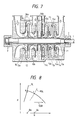
- A rotating stall in a vaneless diffuser is generated when the flow is reduced in a certain compressor stage and the average flow angle α at a diffuser inlet of the stage becomes less than the prescribed value. Under these conditions, because of the rise of static pressure in the radial direction, reverse flow initiates locally at the boundary layers in the diffuser passage and develops into the main flow. The stall area rotates around the axis at low frequency.
- If such a rotating stall occurs, pressure fluctuation caused by it becomes a strong shaft exciting force, as the pressure of the fluid increases. Accordingly, shaft vibration becomes large in a compressor with a high pressure level and driving the compressor becomes difficult, which limits the operating range of the compressor.
- For example, if a rotating stall occurs at point C in a vaneless diffuser stage as shown in the diagram of Fig. 8, the stable driving range (SDR) is at a larger flow rate than Qc. This means that the operating range becomes narrow compared with the case where a rotating stall is assumed not to occur, in which stable operation is possible at a flow rate greater than Qa.
- This problem of vibrations in very high pressure centrifugal compressors was discussed by Ferrara in American Society of Mechanical Engineering (ASME) publication 77-DET-15 of 1977, and attributed to rotating stalls.
- Turusaki in the Japanese magazine "Turbomachine" Vol. 12, 1984, No. 6, pages 323-332, describes rotating stalls in more detail and Nishida et. al. in Reports of the Japanese Society of Mechanical Engineering, March 1988, pages 589-594 discuss the conditions for rotating stalls in vaneless diffusers.
- As a countermeasure against rotating stalls in a vaneless diffuser, it has been usual to reduce the axial passage height of the diffuser from h to h′ as shown in Figs. 9 and 10 to delay the onset of a rotating stall. The ratio of the diffuser passage height to the outlet height b of the impeller is reduced and the radial velocity is increased from Cm to Cm′. The flow. angle α′ at the diffuser inlet is thus larger compared with the flow angle α when the diffuser passage height is larger. Accordingly, it is possible to widen the stable driving range as shown in Fig. 11 by enlarging the inlet flow angle for the same flow rate to delay the onset of a rotating stall. Thus, reducing the passage height has the effect of moving the rotating stall onset point towards the surge point. Rotating stalls can be prevented if the diffuser passage height is decreased greatly compared with the impeller outlet height. However, it is necessary drastically to lower the diffuser passage height completely to prevent rotating stalls, and as the average fluid velocity becomes large in addition to the reduction in passage height by this method, friction loss in the diffuser is increased and performance becomes lower.
- The object of the present invention is to prevent generation of rotating stalls in the diffusers of a high pressure multistage centrifugal compressor, and thus provide a compressor which can be driven stably with high efficiency over a wide operating range.
- The invention adopts vaned diffusers and, in respect of at least two stages, increases the ratio r/R of the outlet radius R of the centrifugal impellers to the diffuser vane leading edge radius r from the rear stage side (delivery side) toward the front stage side (suction side). In another aspect, in at least two stages, the ratio r/R and h/R, where h is the axial passage height of the diffuser (vane axial height), are selected so as to satisfy the following
h/R ≦ 0.04
r/R ≦ 1 + 3.3h/R. - When vanes are provided in accordance with these principles, the flow is forcibly directed by the vane towards the radial direction, and there is hardly any reverse flow. That is to say, the diffuser with vanes has the effect of preventing reverse flow by providing a vane front edge at the inner side of the position where reverse flow is generated first in case of a vaneless configuration.
- According to the invention in one aspect, therefore, there is provided a multi-stage centrifugal compressor having a shaft rotatable on an axis, a plurality of centrifugal impellers fixed on said shaft and having outlets at their peripheries, and conduits connecting said impellers to form a path for fluid undergoing multi-stage compression by said impellers from a suction side to a delivery side of the compressor. The conduits include a plurality of diffusers arranged radially outwardly from the impellers, each impeller and its associated diffuser constituting a stage. At least two of said diffusers are in the form of vaned diffusers. Among the vaned diffusers, a first one has a ratio of diffuser vane leading edge radius to impeller outlet radius larger than the same ratio of a second one which is closer along said path to the delivery side than the first one.
- Usually, there are at least four centrifugal impellers and at least four vaned diffusers. The ratio of diffuser vane leading edge radius to impeller outlet radius preferably increases from each of the vaned diffusers to the next one along the fluid compression path in the direction from the delivery side to the suction side.
- In the high pressure compressor of the invention, preferably in at least one stage, more preferably in all stages having vaned diffusers, the ratio of the axial height of the vanes to the impeller outlet radius is less than 0.04, and may be less than 0.03.
- To increase efficiency, preferably in each stage having a vaned diffuser
r/R ≦ 1 + 3.3 h/R
wherein h is the axial height of the vanes, R is the impeller outlet radius, and r is the diffuser vane leading edge radius. - In addition to the stages having vaned diffusers, there may be at least one stage having a vaneless diffuser, closer to the suction side than the vaned diffusers.
- The compressor of the invention typically has a design operating delivery pressure of at least 50 atmospheres, and in many cases at least 100 atmospheres.
- In each stage having a vaned diffuser, preferably the ratio of the outlet radius of the vanes to the inlet radius of the vanes is not more than 1.2, and the maximum thickness of each vane is preferably in the range 5 to 12% of the chord length of the vane. Typically in each stage having a vaned diffuser, the number of vanes is in the
range 10 to 30, preferably 12 to 20. - Normally, the vanes extend the full axial height of the diffuser.
- In another aspect, the invention provides a multi-stage centrifugal compressor having a shaft rotatable on an axis, a plurality of centrifugal impellers fixed on said shaft and having outlets at their peripheries, and conduits connecting said impellers to form a path for fluid undergoing multi-stage compression by said impellers from a suction side to a delivery side of the compressor. The conduits include a plurality of diffusers arranged radially outwardly from the impellers each impeller and its associated diffuser constituting a stage. At least two of the diffusers are vaned diffusers. In respect of each vaned diffuser and its associated impeller
h/R ≦ 0.04
and r/R ≦ 1 + 3.3h/R
wherein h is the axial height of the vanes, R is the impeller outlet radius, and r is the diffuser vane leading edge radius. - Embodiments of the present invention are given below by way of non-limitative example with reference to the accompanying drawings, in which:-
- Fig. 1 is an axial section of a multistage centrifugal compressor embodying the present invention;
- Fig. 2 is a typical radial section of a stage of the compressor of Fig. 1;
- Fig. 3 is a diagrammatic view of impellers and vaned diffusers in the compressor embodying the invention;
- Fig. 4 is a graph relating certain dimensions of the compressor of Figs. 1 to 3;
- Fig. 5 is an axial section of another embodiment of the invention;
- Fig. 6 is a graph similar to that of Fig. 4 for the embodiment of Fig. 5;
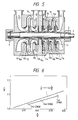
- Fig. 7 is an axial section of yet another compressor embodying the invention; and
- Figs. 8 to 11 are diagrams explaining the properties of a conventional multistage centrifugal compressor.
- In the high pressure multistage centrifugal compressor of Figs. 1 to 3, a
rotating shaft 1 is installed in acasing 3 onbearings 2. Centrifugal impellers 4 (first stage 4a,second stage 4b, third stage 4c,fourth stage 4d) are carried by theshaft 1. The impeller outlet radius R is the same in all four stages, and the axial height h of the diffuser passage is decreased according to the change of volume flow rate. The outlet and the inlet of each adjacent pair ofimpellers 4 in the sequence are connected by passages 5 (first stage 5a, second stage 5b,third stage 5c) formed in thecasing 3. The inlet of thecentrifugal impeller 4a of the front stage (suction side) is connected to aninlet port 6 of thecasing 3 and the outlet of thecentrifugal impeller 4d at the rear stage (delivery side) is connected to an outlet port 7 of thecasing 3. In the passage 5, vaned diffusers 8 (first stage 8a,second stage 8b,third stage 8c,fourth stage 8d) are provided at the outlet side of eachimpeller impeller - Figs. 3 and 4 indicate relative values of the outlet radius R of the
impellers 4, the height h of thevaned diffusers 8 and the leading edge radius r of the diffuser vanes. These values satisfy the following relation:-
r/R < 1 + 3.3 h/R (1) - In this case, the radius at the rear edge of the diffuser vanes is not explicitly specified.
- The effect of this embodiment will now be described.
- In such a multistage centrifugal compressor, the fluid is compressed as it flows toward the rear stage, volume flow rate is decreased, and consequently the diffuser passage height h becomes generally smaller, but the smaller the diffuser passage height h, the more reverse flow is generated at the inner diameter region of the diffuser. The relation between this passage height h and the reverse flow onset radius r1 is approximated by the following equation (2) from calculation.
r1/R ≒ 1 + 3.3 h/R (2) - In other words, the position of the radius where the reverse flow occurs first, for a given passage height h is shown by the above equation.
- As explained above, a rotating stall is generated in the diffuser when this reverse flow develops and forms a stall zone which rotates in the diffuser. Accordingly, if the first reverse flow is restrained in the diffuser, rotating stalls can be prevented.
- In vaned diffusers, if the vane front edge radius r becomes small, the noise and strength of the vane are adversely affected since high speed fluid coming out of the
centrifugal impeller 4 collides with the vane. As the inlet radius r of the vanes increases towards the front stage (suction side) in the range satisfying the above relation (1) in this embodiment, it is more beneficial in terms of noise and strength of the vane, compared with the case where the ratio r/R is fixed at a small value and is constant for all stages. - Moreover, the
vaned diffusers 8 prevent rotating stalls without the reduction of the passage height h required for the vaneless diffusers, and the passage length passing through the diffusers is also shortened and friction loss is small. Therefore a high level of efficiency can be obtained since the flow is forcibly directed by the vanes and flow angle is large. - In this embodiment therefore, rotating stalls can be prevented in all stages and a multistage centrifugal compressor that achieves high efficiency and can be operated stably over a wide range is obtained.
- The embodiment of Figs. 5 and 6 is a multistage centrifugal compressor with five stages in which intercooling of the fluid is carried out between the low pressure stage side and the high pressure stage side. The same reference numbers are used to designate parts corresponding to the parts shown in Figs. 1 and 2.
- Centrifugal impellers 11 (first stage 11a,
second stage 11b,third stage 11c) of the high pressure stage side group with the same outlet radius R as well as centrifugal impellers 10 (first stage 10a,second stage 10b) of the low pressure stage side group with the same outlet radius R are fixed on therotational shaft 1. The low pressure stage side group has vaneless diffusers 12 (first stage 12a,second stage 12b) and areturn channel 13, and the high pressure stage side group has vaned diffusers 14 (first stage 14a,second stage 14b, third stage 14c) and return channels 15 (first stage 15a,second stage 15b). The reason why vaneless diffusers are used for the low pressure stage side group and vaned diffusers for the high pressure stage side group is as follows. - The impellers of this multistage centrifugal compressor have a wide range of specific speeds. Since at the low pressure stage side (front stage side) the specific speed is large and the flow angle of the diffusers is large for design convenience, rotating stalls hardly occur. At the low pressure level, even if a rotating stall is generated, its small shaft exciting force does not cause a problem.
- In this embodiment, vaned diffusers are provided for the high pressure stage group where rotating stalls cause a problem, and the leading edge radius ratio of each diffuser is set as shown in Fig. 6.
- Therefore, in this embodiment, rotating stalls in the diffusers can be prevented in the three stages on the rear stage side, and the compressor properties of high efficiency and a wide stable driving range can be obtained.
- Still another embodiment is shown in Fig. 7, which is the same as that of Figs. 5 and 6 except that vaned diffusers are used at the low pressure stage side group. The ratio r/R of the leading edge radius r of these
diffuser vanes 16 to the centrifugal impeller outlet radius R is constant. Vaned diffusers are used in the high pressure stage side group and the ratio r/R of the leading edge radius r of the diffuser vanes 14 (first stage 14a,second stage 14b) to the impeller outlet radius R satisfy the relationship with the ratio h/R of the diffuser vane height h to the impeller outlet radius R as follows:-
r/R < l + 3.3 h/R
and the ratio r/R increases from the rear stage side to the front stage side in this group. - With this embodiment, using the vaned diffusers with the constant ratio r/R for the low pressure stage side group and giving it high efficiency, the compressor can be driven very efficiently.
- Moreover, highly efficient operation is achieved in this compressor by making the ratio r/R of the diffuser leading edge radius of the low pressure stage side group and the impeller outlet radius R constant and setting this ratio r/R to satisfy the relationship with the ratio h/R of the diffuser vane height h to the impeller outlet radius R:-
r/R < 1 + 3.3 h/R - In the above embodiments, if the flow through the impellers is increased more than the flow through each stage by increasing the leakage flow between the inlets and the outlets of the centrifugal impellers, and it is arranged that the impellers work only at the large flow side, more effective prevention of rotating stalls is achieved.
- Dimensions and design operating conditions of two multistage compressors of the invention are given in Tables 1 and 2 below. The compressors are generally as shown in Fig. 1; the compressor of Table 1 has four stages, whereas the compressor of Table 2 has three stages.
Table 1 1st stage 2nd stage 3rd stage 4th stage Impeller outlet radius R 85 mm 85 mm 75 mm 75 mm Vane leading edge radius r 93.5mm 91.8mm 78.5mm 77.5mm Vane trailing edge radius r′ 107.5mm 105.5mm 90.3mm 98 mm Number of vanes 18 18 18 18 Vane height in axial direction h 3.0mm 2.6mm 2.0mm 1.8mm Radius ratio r/R 1.1 1.08 1.047 1.033 Height ratio h/R 0.035 0.031 0.027 0.024 Shaft rotational speed : 14370 rpm Gas : CO₂ Pressure Suction/Delivery : 45/140 atmospheres Table 2 1st stage 2nd stage 3rd stage Impeller outlet radius R 145 mm 145 mm 145 mm Vane leading edge radius r 155.2 152.3 149.4 Vane trailing edge radius r′ 178.4 175.1 171.8 Number of vanes 16 16 16 Vane height in axial direction h 3.7mm 3.3mm 3.0mm Radius ratio r/R 1.07 1.05 1.03 Height ratio h/R 0.026 0.023 0.021 Shaft rotational speed : 11600 rpm Gas : Ethylene Pressure Suction/Delivery : 65/122 atmospheres
Claims (16)
r/R ≦ 1 + 3.3 h/R
wherein h is the axial height of the vanes, R is the impeller outlet radius, and r is the diffuser vane leading edge radius.
h/R ≦ 0.04
and r/R ≦ 1 + 3.3h/R
wherein h is the axial height of the vanes, R is the impeller outlet radius, and r is the diffuser vane leading edge radius.
Applications Claiming Priority (2)
| Application Number | Priority Date | Filing Date | Title |
|---|---|---|---|
| JP228745/88 | 1988-09-14 | ||
| JP63228745A JPH0646035B2 (en) | 1988-09-14 | 1988-09-14 | Multi-stage centrifugal compressor |
Publications (3)
| Publication Number | Publication Date |
|---|---|
| EP0359514A2 true EP0359514A2 (en) | 1990-03-21 |
| EP0359514A3 EP0359514A3 (en) | 1990-07-04 |
| EP0359514B1 EP0359514B1 (en) | 1992-12-23 |
Family
ID=16881164
Family Applications (1)
| Application Number | Title | Priority Date | Filing Date |
|---|---|---|---|
| EP89309233A Expired - Lifetime EP0359514B1 (en) | 1988-09-14 | 1989-09-12 | Multistage centrifugal compressor |
Country Status (5)
| Country | Link |
|---|---|
| US (1) | US4938661A (en) |
| EP (1) | EP0359514B1 (en) |
| JP (1) | JPH0646035B2 (en) |
| CN (1) | CN1015489B (en) |
| DE (1) | DE68904020T2 (en) |
Cited By (8)
| Publication number | Priority date | Publication date | Assignee | Title |
|---|---|---|---|---|
| EP1311315A1 (en) * | 2000-07-05 | 2003-05-21 | Compumedics Sleep Pty. Ltd. | Dual-pressure blower for positive air pressure device |
| EP1990544A2 (en) | 2007-05-10 | 2008-11-12 | Hitachi Plant Technologies, Ltd. | Multistage centrifugal compressor |
| EP2149709A3 (en) * | 2008-07-30 | 2011-10-12 | Hitachi Plant Technologies, Ltd. | Multistage centrifugal compressor |
| CN104632645A (en) * | 2014-11-06 | 2015-05-20 | 沈阳斯特机械制造有限公司 | Double inlet multistage centrifugal compressor |
| EP2977619A4 (en) * | 2013-03-21 | 2016-12-21 | Mitsubishi Heavy Ind Ltd | Centrifugal fluid machine |
| RU183324U1 (en) * | 2017-12-29 | 2018-09-18 | федеральное государственное автономное образовательное учреждение высшего образования "Санкт-Петербургский политехнический университет Петра Великого" (ФГАОУ ВО "СПбПУ") | Airless diffuser low flow centrifugal compressor stage |
| WO2019160550A1 (en) * | 2018-02-15 | 2019-08-22 | Dresser-Rand Company | Centrifugal compressor achieving high pressure ratio |
| CN112177949A (en) * | 2019-07-04 | 2021-01-05 | 三菱重工业株式会社 | Multistage centrifugal compressor |
Families Citing this family (47)
| Publication number | Priority date | Publication date | Assignee | Title |
|---|---|---|---|---|
| US5071317A (en) * | 1990-06-04 | 1991-12-10 | Alan Leach | Centrifugal pump having a unitary one-piece diffusion casing and a unitary one piece turbine impeller unit |
| US5125806A (en) * | 1990-06-18 | 1992-06-30 | Sundstrand Corporation | Integrated variable speed compressor drive system |
| DE4115805A1 (en) * | 1991-05-15 | 1992-11-19 | Bosch Gmbh Robert | RADIAL BLOWER WITH A BLOWING WHEEL IN A SPIRAL CASE |
| US5297930A (en) * | 1991-12-31 | 1994-03-29 | Cornell Research Foundation, Inc. | Rotating stall suppression |
| US5330318A (en) * | 1992-05-28 | 1994-07-19 | Nikkiso Co., Ltd. | Centrifugal pump with an improved axial diffusor |
| DE4234739C1 (en) * | 1992-10-15 | 1993-11-25 | Gutehoffnungshuette Man | Gearbox multi-shaft turbo compressor with feedback stages |
| US5363674A (en) * | 1993-05-04 | 1994-11-15 | Ecoair Corp. | Zero superheat refrigeration compression system |
| US5320489A (en) * | 1993-06-01 | 1994-06-14 | Ingersoll-Dresser Pump Company | Diffuser for a centrifugal pump |
| WO1996028662A1 (en) * | 1995-03-13 | 1996-09-19 | Hitachi, Ltd. | Centrifugal hydraulic machine |
| JP3168865B2 (en) * | 1995-03-20 | 2001-05-21 | 株式会社日立製作所 | Impeller for multistage centrifugal compressor and method of manufacturing the same |
| CA2303970C (en) * | 1997-09-19 | 2009-09-08 | Respironics, Inc. | Medical ventilator |
| JPH11148120A (en) * | 1997-11-14 | 1999-06-02 | Kioritz Corp | Portable ventilating operation machine |
| FR2774137B1 (en) * | 1998-01-28 | 2000-02-18 | Inst Francais Du Petrole | WET GAS COMPRESSION DEVICE COMPRISING AN INTEGRATED COMPRESSION / SEPARATION STAGE |
| US6506023B1 (en) * | 2000-09-05 | 2003-01-14 | Industrial Technology Research Institute | Integrally formed stamping sheet-metal blades having 3D structure |
| US8550775B2 (en) * | 2002-08-13 | 2013-10-08 | Honeywell International Inc. | Compressor |
| ITMI20022661A1 (en) * | 2002-12-17 | 2004-06-18 | Nuovo Pignone Spa | IMPROVED DIFFUSER FOR A CENTRIFUGAL COMPRESSOR. |
| ES2268912B1 (en) * | 2003-03-13 | 2008-02-16 | Indar Maquinas Hidraulicas, S.L | MULTIETAPA ELECTRIC PUMP GROUP. |
| US8016557B2 (en) * | 2005-08-09 | 2011-09-13 | Praxair Technology, Inc. | Airfoil diffuser for a centrifugal compressor |
| CN1912395B (en) * | 2005-08-09 | 2011-01-19 | 海巴鼓风机有限公司 | Middle-speed high-pressure multi-stage centrifugal blowing machine |
| JP5314256B2 (en) * | 2007-06-06 | 2013-10-16 | 三菱重工業株式会社 | SEALING DEVICE FOR ROTARY FLUID MACHINE AND ROTARY FLUID MACHINE |
| JP5314255B2 (en) * | 2007-06-06 | 2013-10-16 | 三菱重工業株式会社 | SEALING DEVICE FOR ROTARY FLUID MACHINE AND ROTARY FLUID MACHINE |
| IT1392796B1 (en) | 2009-01-23 | 2012-03-23 | Nuovo Pignone Spa | REVERSIBLE GAS INJECTION AND EXTRACTION SYSTEM FOR ROTARY FLUID MACHINES |
| US9097258B2 (en) * | 2009-06-25 | 2015-08-04 | General Electric Company | Supersonic compressor comprising radial flow path |
| JP2011043130A (en) * | 2009-08-24 | 2011-03-03 | Hitachi Appliances Inc | Centrifugal compressor and refrigeration equipment |
| JP2011132877A (en) * | 2009-12-24 | 2011-07-07 | Mitsubishi Heavy Ind Ltd | Multistage radial turbine |
| JP5613006B2 (en) * | 2010-10-18 | 2014-10-22 | 株式会社日立製作所 | Multistage centrifugal compressor and its return channel |
| CN105051372B (en) * | 2013-01-31 | 2017-05-31 | 丹佛斯公司 | The centrifugal compressor of the opereating specification with extension |
| US20140321979A1 (en) * | 2013-04-24 | 2014-10-30 | Hamilton Sundstrand Corporation | Turbine nozzle piece parts with hvoc coatings |
| JP6158008B2 (en) * | 2013-09-18 | 2017-07-05 | 三菱重工業株式会社 | Rotating machine |
| CN103557166B (en) * | 2013-10-15 | 2016-06-08 | 沈阳斯特机械制造有限公司 | A kind of multistage centrifugal compressor |
| CN104179697A (en) * | 2014-08-07 | 2014-12-03 | 珠海格力电器股份有限公司 | Multi-stage compressor and air conditioner |
| US10375901B2 (en) | 2014-12-09 | 2019-08-13 | Mtd Products Inc | Blower/vacuum |
| DE102015219556A1 (en) | 2015-10-08 | 2017-04-13 | Rolls-Royce Deutschland Ltd & Co Kg | Diffuser for radial compressor, centrifugal compressor and turbo machine with centrifugal compressor |
| CN109072930B (en) | 2016-02-04 | 2021-08-13 | 丹佛斯公司 | Centrifugal compressor and method of operating a centrifugal compressor |
| JP6667323B2 (en) * | 2016-02-29 | 2020-03-18 | 三菱重工コンプレッサ株式会社 | Centrifugal rotating machine |
| CN106151063B (en) * | 2016-08-29 | 2019-12-17 | 沈阳斯特机械制造有限公司 | CO circulating gas compressor |
| WO2018096670A1 (en) * | 2016-11-28 | 2018-05-31 | 三菱重工コンプレッサ株式会社 | Rotor securing jig and rotor storage unit |
| JP6935312B2 (en) * | 2017-11-29 | 2021-09-15 | 三菱重工コンプレッサ株式会社 | Multi-stage centrifugal compressor |
| US10280850B1 (en) | 2018-01-23 | 2019-05-07 | Ford Global Technologies, Llc | Double-ended electric supercharger |
| US10914494B2 (en) * | 2018-02-27 | 2021-02-09 | Newco H20 Llc | Segmented cavitation boiler |
| CN109268295A (en) * | 2018-11-20 | 2019-01-25 | 势加透博(北京)科技有限公司 | A kind of two-stage air compression system with diameter axial direction diffuser |
| US11098730B2 (en) | 2019-04-12 | 2021-08-24 | Rolls-Royce Corporation | Deswirler assembly for a centrifugal compressor |
| CN111550444A (en) * | 2020-05-11 | 2020-08-18 | 中国航发湖南动力机械研究所 | Mixed blade radial/oblique diffuser |
| US11286952B2 (en) | 2020-07-14 | 2022-03-29 | Rolls-Royce Corporation | Diffusion system configured for use with centrifugal compressor |
| US11441516B2 (en) | 2020-07-14 | 2022-09-13 | Rolls-Royce North American Technologies Inc. | Centrifugal compressor assembly for a gas turbine engine with deswirler having sealing features |
| US11578654B2 (en) | 2020-07-29 | 2023-02-14 | Rolls-Royce North American Technologies Inc. | Centrifical compressor assembly for a gas turbine engine |
| US20240060507A1 (en) * | 2022-08-22 | 2024-02-22 | FoxRES LLC | Sculpted Low Solidity Vaned Diffuser |
Citations (5)
| Publication number | Priority date | Publication date | Assignee | Title |
|---|---|---|---|---|
| GB586726A (en) * | 1943-04-13 | 1947-03-28 | Bendix Aviat Corp | Superchargers |
| FR931344A (en) * | 1946-07-26 | 1948-02-19 | Improvements to turbo-machines | |
| US2469214A (en) * | 1946-03-19 | 1949-05-03 | Gen Electric | Centrifugal compressor |
| CH315988A (en) * | 1953-11-23 | 1956-09-15 | Sulzer Ag | Multi-stage centrifugal compressor |
| DE1428170A1 (en) * | 1963-04-16 | 1969-01-23 | Gutehoffnungshuette Sterkrade | Multi-stage radial turbo work machine, in particular multi-stage centrifugal compressor |
Family Cites Families (9)
| Publication number | Priority date | Publication date | Assignee | Title |
|---|---|---|---|---|
| US1580878A (en) * | 1922-05-24 | 1926-04-13 | Dufour Leon | Combustion turbine |
| US2224010A (en) * | 1938-08-31 | 1940-12-03 | Donn R Barber | Spearhead nozzle |
| US2995293A (en) * | 1959-04-21 | 1961-08-08 | Ingenieurbureau Dr Ing Alfred | Guide means on impellers for centrifugal pumps or blowers |
| US3105632A (en) * | 1960-03-14 | 1963-10-01 | Dresser Ind | High pressure centrifugal compressor |
| US3927763A (en) * | 1970-12-15 | 1975-12-23 | Bbc Sulzer Turbomaschinen | Installation unit for a multistage radial compressor |
| SU522343A1 (en) * | 1974-01-18 | 1976-07-25 | Николаевский Ордена Трудового Красного Знамени Кораблестроительный Институт Им.Адмирала С.О.Макарова | Centrifugal compressor stage |
| JPS5598692A (en) * | 1979-01-24 | 1980-07-26 | Hitachi Ltd | Multistage centrifugal fluid machine |
| JPS5639897U (en) * | 1979-09-05 | 1981-04-14 | ||
| JPH0640951Y2 (en) * | 1986-04-01 | 1994-10-26 | 三菱重工業株式会社 | Centrifugal compressor |
-
1988
- 1988-09-14 JP JP63228745A patent/JPH0646035B2/en not_active Expired - Fee Related
-
1989
- 1989-09-08 US US07/404,597 patent/US4938661A/en not_active Expired - Lifetime
- 1989-09-12 EP EP89309233A patent/EP0359514B1/en not_active Expired - Lifetime
- 1989-09-12 DE DE8989309233T patent/DE68904020T2/en not_active Expired - Lifetime
- 1989-09-14 CN CN89107871A patent/CN1015489B/en not_active Expired
Patent Citations (5)
| Publication number | Priority date | Publication date | Assignee | Title |
|---|---|---|---|---|
| GB586726A (en) * | 1943-04-13 | 1947-03-28 | Bendix Aviat Corp | Superchargers |
| US2469214A (en) * | 1946-03-19 | 1949-05-03 | Gen Electric | Centrifugal compressor |
| FR931344A (en) * | 1946-07-26 | 1948-02-19 | Improvements to turbo-machines | |
| CH315988A (en) * | 1953-11-23 | 1956-09-15 | Sulzer Ag | Multi-stage centrifugal compressor |
| DE1428170A1 (en) * | 1963-04-16 | 1969-01-23 | Gutehoffnungshuette Sterkrade | Multi-stage radial turbo work machine, in particular multi-stage centrifugal compressor |
Cited By (12)
| Publication number | Priority date | Publication date | Assignee | Title |
|---|---|---|---|---|
| EP1311315A1 (en) * | 2000-07-05 | 2003-05-21 | Compumedics Sleep Pty. Ltd. | Dual-pressure blower for positive air pressure device |
| EP1311315A4 (en) * | 2000-07-05 | 2006-04-05 | Compumedics Sleep Pty Ltd | Dual-pressure blower for positive air pressure device |
| EP1990544A2 (en) | 2007-05-10 | 2008-11-12 | Hitachi Plant Technologies, Ltd. | Multistage centrifugal compressor |
| EP1990544A3 (en) * | 2007-05-10 | 2009-06-17 | Hitachi Plant Technologies, Ltd. | Multistage centrifugal compressor |
| US8287236B2 (en) | 2007-05-10 | 2012-10-16 | Hitachi Plant Technologies, Ltd. | Multistage centrifugal compressor |
| EP2149709A3 (en) * | 2008-07-30 | 2011-10-12 | Hitachi Plant Technologies, Ltd. | Multistage centrifugal compressor |
| EP2977619A4 (en) * | 2013-03-21 | 2016-12-21 | Mitsubishi Heavy Ind Ltd | Centrifugal fluid machine |
| US10197063B2 (en) | 2013-03-21 | 2019-02-05 | Mitsubishi Heavy Industries Compressor Corporation | Centrifugal fluid machine |
| CN104632645A (en) * | 2014-11-06 | 2015-05-20 | 沈阳斯特机械制造有限公司 | Double inlet multistage centrifugal compressor |
| RU183324U1 (en) * | 2017-12-29 | 2018-09-18 | федеральное государственное автономное образовательное учреждение высшего образования "Санкт-Петербургский политехнический университет Петра Великого" (ФГАОУ ВО "СПбПУ") | Airless diffuser low flow centrifugal compressor stage |
| WO2019160550A1 (en) * | 2018-02-15 | 2019-08-22 | Dresser-Rand Company | Centrifugal compressor achieving high pressure ratio |
| CN112177949A (en) * | 2019-07-04 | 2021-01-05 | 三菱重工业株式会社 | Multistage centrifugal compressor |
Also Published As
| Publication number | Publication date |
|---|---|
| EP0359514B1 (en) | 1992-12-23 |
| US4938661A (en) | 1990-07-03 |
| JPH0278788A (en) | 1990-03-19 |
| EP0359514A3 (en) | 1990-07-04 |
| DE68904020T2 (en) | 1993-04-29 |
| CN1015489B (en) | 1992-02-12 |
| DE68904020D1 (en) | 1993-02-04 |
| JPH0646035B2 (en) | 1994-06-15 |
| CN1041992A (en) | 1990-05-09 |
Similar Documents
| Publication | Publication Date | Title |
|---|---|---|
| EP0359514A2 (en) | Multistage centrifugal compressor | |
| US5709531A (en) | Centrifugal compressor and vaned diffuser | |
| JP3488718B2 (en) | Centrifugal compressors and diffusers for centrifugal compressors | |
| US6371724B2 (en) | Centrifugal fluid machine | |
| US5178516A (en) | Centrifugal compressor | |
| EP0568069B1 (en) | Turbomolecular vacuum pumps | |
| KR100548709B1 (en) | Turbomachinery impeller | |
| US5062766A (en) | Turbo compressor | |
| US5228832A (en) | Mixed flow compressor | |
| EP0982502B1 (en) | Centrifugal compressor | |
| EP0155419B1 (en) | Noise control for conically ported liquid ring pumps | |
| JPH06288384A (en) | Turbomachinery | |
| US20210115943A1 (en) | Centrifugal compressor | |
| US5143511A (en) | Regenerative centrifugal compressor | |
| EP0226039A1 (en) | Vacuum pump apparatus | |
| EP3722616A1 (en) | Deswirler assembly for a centrifugal compressor | |
| WO2018180057A1 (en) | Centrifugal compressor and turbo refrigerator | |
| JP2757922B2 (en) | Centrifugal compressor | |
| KR100339550B1 (en) | Diffuser for turbo compressor | |
| USRE33129E (en) | Vacuum pump | |
| RU2162164C1 (en) | Turbocompressor | |
| JP2023001450A (en) | multistage centrifugal fluid machine | |
| JP2002357199A (en) | Multi-stage turbo-compressor | |
| JP2003166491A (en) | Multi-stage centrifugal pump | |
| JPH0278792A (en) | Turbo type compressor |
Legal Events
| Date | Code | Title | Description |
|---|---|---|---|
| PUAI | Public reference made under article 153(3) epc to a published international application that has entered the european phase |
Free format text: ORIGINAL CODE: 0009012 |
|
| 17P | Request for examination filed |
Effective date: 19891030 |
|
| AK | Designated contracting states |
Kind code of ref document: A2 Designated state(s): CH DE IT LI |
|
| PUAL | Search report despatched |
Free format text: ORIGINAL CODE: 0009013 |
|
| AK | Designated contracting states |
Kind code of ref document: A3 Designated state(s): CH DE IT LI |
|
| 17Q | First examination report despatched |
Effective date: 19920211 |
|
| GRAA | (expected) grant |
Free format text: ORIGINAL CODE: 0009210 |
|
| AK | Designated contracting states |
Kind code of ref document: B1 Designated state(s): CH DE IT LI |
|
| REF | Corresponds to: |
Ref document number: 68904020 Country of ref document: DE Date of ref document: 19930204 |
|
| ITF | It: translation for a ep patent filed |
Owner name: MODIANO & ASSOCIATI S.R.L. |
|
| PLBE | No opposition filed within time limit |
Free format text: ORIGINAL CODE: 0009261 |
|
| STAA | Information on the status of an ep patent application or granted ep patent |
Free format text: STATUS: NO OPPOSITION FILED WITHIN TIME LIMIT |
|
| 26N | No opposition filed | ||
| REG | Reference to a national code |
Ref country code: CH Ref legal event code: NV Representative=s name: TROESCH SCHEIDEGGER WERNER AG Ref country code: CH Ref legal event code: PUE Owner name: HITACHI PLANT TECHNOLOGIES, LTD. Free format text: HITACHI, LTD#6, KANDA SURUGADAI 4-CHOME#CHIYODA-KU/TOKYO (JP) -TRANSFER TO- HITACHI PLANT TECHNOLOGIES, LTD.#1-14, UCHIKANDA 1-CHOME#CHIYODA-KU, TOKYO (JP) |
|
| PGFP | Annual fee paid to national office [announced via postgrant information from national office to epo] |
Ref country code: CH Payment date: 20080723 Year of fee payment: 20 |
|
| PGFP | Annual fee paid to national office [announced via postgrant information from national office to epo] |
Ref country code: IT Payment date: 20080716 Year of fee payment: 20 |
|
| PGFP | Annual fee paid to national office [announced via postgrant information from national office to epo] |
Ref country code: DE Payment date: 20080908 Year of fee payment: 20 |
|
| REG | Reference to a national code |
Ref country code: CH Ref legal event code: PL |