EP0358989A2 - Position or speed sensing apparatus - Google Patents
Position or speed sensing apparatus Download PDFInfo
- Publication number
- EP0358989A2 EP0358989A2 EP89115552A EP89115552A EP0358989A2 EP 0358989 A2 EP0358989 A2 EP 0358989A2 EP 89115552 A EP89115552 A EP 89115552A EP 89115552 A EP89115552 A EP 89115552A EP 0358989 A2 EP0358989 A2 EP 0358989A2
- Authority
- EP
- European Patent Office
- Prior art keywords
- pulse
- speed
- signal
- analog
- moving body
- Prior art date
- Legal status (The legal status is an assumption and is not a legal conclusion. Google has not performed a legal analysis and makes no representation as to the accuracy of the status listed.)
- Granted
Links
Images


Classifications
-
- G—PHYSICS
- G01—MEASURING; TESTING
- G01P—MEASURING LINEAR OR ANGULAR SPEED, ACCELERATION, DECELERATION, OR SHOCK; INDICATING PRESENCE, ABSENCE, OR DIRECTION, OF MOVEMENT
- G01P3/00—Measuring linear or angular speed; Measuring differences of linear or angular speeds
- G01P3/42—Devices characterised by the use of electric or magnetic means
- G01P3/44—Devices characterised by the use of electric or magnetic means for measuring angular speed
- G01P3/48—Devices characterised by the use of electric or magnetic means for measuring angular speed by measuring frequency of generated current or voltage
- G01P3/481—Devices characterised by the use of electric or magnetic means for measuring angular speed by measuring frequency of generated current or voltage of pulse signals
- G01P3/489—Digital circuits therefor
-
- G—PHYSICS
- G01—MEASURING; TESTING
- G01D—MEASURING NOT SPECIALLY ADAPTED FOR A SPECIFIC VARIABLE; ARRANGEMENTS FOR MEASURING TWO OR MORE VARIABLES NOT COVERED IN A SINGLE OTHER SUBCLASS; TARIFF METERING APPARATUS; MEASURING OR TESTING NOT OTHERWISE PROVIDED FOR
- G01D5/00—Mechanical means for transferring the output of a sensing member; Means for converting the output of a sensing member to another variable where the form or nature of the sensing member does not constrain the means for converting; Transducers not specially adapted for a specific variable
- G01D5/12—Mechanical means for transferring the output of a sensing member; Means for converting the output of a sensing member to another variable where the form or nature of the sensing member does not constrain the means for converting; Transducers not specially adapted for a specific variable using electric or magnetic means
- G01D5/244—Mechanical means for transferring the output of a sensing member; Means for converting the output of a sensing member to another variable where the form or nature of the sensing member does not constrain the means for converting; Transducers not specially adapted for a specific variable using electric or magnetic means influencing characteristics of pulses or pulse trains; generating pulses or pulse trains
- G01D5/24409—Interpolation using memories
-
- G—PHYSICS
- G01—MEASURING; TESTING
- G01D—MEASURING NOT SPECIALLY ADAPTED FOR A SPECIFIC VARIABLE; ARRANGEMENTS FOR MEASURING TWO OR MORE VARIABLES NOT COVERED IN A SINGLE OTHER SUBCLASS; TARIFF METERING APPARATUS; MEASURING OR TESTING NOT OTHERWISE PROVIDED FOR
- G01D5/00—Mechanical means for transferring the output of a sensing member; Means for converting the output of a sensing member to another variable where the form or nature of the sensing member does not constrain the means for converting; Transducers not specially adapted for a specific variable
- G01D5/12—Mechanical means for transferring the output of a sensing member; Means for converting the output of a sensing member to another variable where the form or nature of the sensing member does not constrain the means for converting; Transducers not specially adapted for a specific variable using electric or magnetic means
- G01D5/244—Mechanical means for transferring the output of a sensing member; Means for converting the output of a sensing member to another variable where the form or nature of the sensing member does not constrain the means for converting; Transducers not specially adapted for a specific variable using electric or magnetic means influencing characteristics of pulses or pulse trains; generating pulses or pulse trains
- G01D5/246—Mechanical means for transferring the output of a sensing member; Means for converting the output of a sensing member to another variable where the form or nature of the sensing member does not constrain the means for converting; Transducers not specially adapted for a specific variable using electric or magnetic means influencing characteristics of pulses or pulse trains; generating pulses or pulse trains by varying the duration of individual pulses
Landscapes
- Physics & Mathematics (AREA)
- General Physics & Mathematics (AREA)
- Transmission And Conversion Of Sensor Element Output (AREA)
- Control Of Position Or Direction (AREA)
Abstract
Description
- The present invention relates to apparatus and method for detecting the position and/or speed of a rotating body (a rotating object) or a moving body (a moving object). The present invention also relates to systems which transmit to a controller an output signal from a sinusoidal wave encoder as a position detector.
- An encoder is known which detects the rotational angle of a rotating body or the position of a moving body magnetically or optically. The encoder changes the signal from the rotating body or the moving body to a pulse signal, counts rise or fall edges of the signal to detect the position of the rotating body or moving body.
- The apparatus disclosed in a Japanese publication JP-A-81185 changes encoder signals to pulse signals, and counts same to obtain the speed or position of a rotating body or a moving body. The apparatus includes a high-resolution encoder used at low speed and a lower-resolution encoder used at higher speed.
- Data on the actual speed is obtained by counting pulses produced for a predetermined sample time or a predetermined number of (two or more) inter-pulse time intervals.
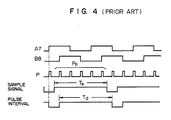
- A specific speed detection process will now be described with reference to FIG. 4 in which reference character P denotes a train of pulses obtained from the encoder, and Ts is a sample time which is about 0.5 msec in the particular example. A high accuracy value indicative of the detected speed is obtained by detecting the number of pulses Pn produced for a sample time Ts, and the interval Td between the pulses Pn, and performing the following division:

- When the rotating body or moving body falls in a low or extremely low speed region, no pulses Pn are produced in a predetermined sample time to thereby render the detection of the speed uncertain.
- This process is hereinafter referred to as a pulse detecting system. According to this system, it it impossible to detect a position falling between adjacent pulses even if the number of pulses per rotation and resolution are increased using excellent manufacturing techniques.
- For example, a direct drive motor which drives a load using no gears can rotate at an extremely low speed lower than one rotation per minute. According to the pulse detection system, there are no plurality of pulses in a sample time, or there are only a very few pulses, if any, and therefore, stabilized speed control cannot be expected. It is obvious that the use of long sample time increases the number of pulses to be detected in the sample time to thereby enable stabilized control, of course. However, the responsiveness to control is lowered.
- The original signal from the encoder generally takes the form of a sine wave signal or a signal similar thereto. In a sine wave signal detection system which uses the analog value of the original signal as it is as a position signal, a superhigh resolution of more than a million pulse per rotation is obtained to thereby enable substantially stepless position detection and to bring about a shortened sample time and rapid control.
- On the other hand, since the analog signal is used, the encoder and the controller cannot be connected in an isolated manner through a photocoupler for a signal transmission. Therefore, the controller is likely to be influenced by noise to thereby render it impossible to provide a long transmission distance.
- It is an object of the present invention to realize an extremely low speed rotation or movement of a rotating or a moving body (object) without pulsation, to improve frequency response characteristics to provide rapid control of the rotating body or the moving body, to insulate the transmission path between the encoder and the controller for transmitting purposes, to increase the resistance of the controller to noise, or to increase the length of the signal transmission path.
- According to one aspect of the present invention, a since or sinusoidal wave signal from a position detector is used as an analog value to finely detect a position (a finely detected position), and a rise or fall edge of the sine wave signal is used to coarsely detect a position (a coarsely detected position). The position or speed of the rotating or moving body (object) is detected using the coarse position signal at high speed and the fine position signal at lower speed.
- More specifically, the present invention provides a method of detecting the position or speed, using a position or speed detecting apparatus including a position detector for outputting two analog signals out of phase, means for outputting a signal indicative of the detected a fine position from the analog values of the analog signals, and means for converting the analog values to a pulse signal as a signal indicative of the detected coarse position, comprising the steps of:
detecting the position or speed of a moving body using the signal indicative of the detected coarse position when the moving body is at high speed; and
detecting the position or speed of the moving body using the signal indicative of the detected fine position when the moving body is at low speed. - The specific structure of a position detecting apparatus for realizing this method comprises:
a position detector for outputting analog signals such as sine waves or triangular waves out of phase depending on the movement of a rotating or moving body;
a pair of PWM pulse forming circuits for performing pulse width modulation on those analog signals from the position detector;
a pair of analog converters for converting the PWM pulse signals to analog signals;
a pair of pulse shaping circuits for shaping the analog signals to square pulse signals;
a coarse position detector for detecting a coarse position of the moving or rotating body from the edges of the pulse signals outputted from the pulse shaping circuits; and
a fine position detector for detecting a fine position of the rotating or moving body from the analog values of the analog signals. - In addition, a pair of photocouplers is disposed in the transmission paths connecting the corresponding PWM pulse forming circuits and the controller side to transmit an electrical signal therethrough in an electrically isolated manner to thereby improve resistance to noise.
- This arrangement provides optimal control from high speed to extremely low speed at which speed detection is effected with superhigh resolution using analog values, so that uneven rotation is prevented. The transmission through the photocoupler serves to shut off noise from the position detector (encoder) to thereby prevent the malfunction of the controller.
-
- FIG. 1 shows a position and speed detector according to one embodiment of the present invention.
- FIG. 2 shows another embodiment.
- FIG. 3 shows a modification of the embodiment of FIG. 2.
- FIG. 4 is a timing chart in the use of a pulse detection system.
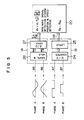
- FIG. 5 is a block diagram of a sine wave signal detection system.
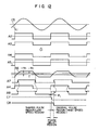
- FIG. 6 is a timing chart in the use of the sine wave signal detection system.
- FIG. 7 is a timing chart in the use of PWM transmission at low speed.
- FIG. 8 is a timing chart in pulse transmission at high speed.
- FIG. 9 is an illustration involving respective waveform switching points.
- FIG. 10 shows a switching circuit to prevent hazards.
- FIG. 11 is a timing chart for switching between a sine wave pulse and an insulating pulse when the speed changes from low to high.
- FIG. 12 is a chart indicative of the timing for switching between a sine wave pulse and an insulating pulse when the speed changes from high to low.
- FIG. 13 shows a further embodiment.
- A specific embodiment of the present invention will now be described with reference to the drawings. First, a sine wave signal detection system will be outlined with reference to FIGs. 5 and 6. A speed detector is a sine wave encoder. This is referred to as a sine wave signal detection system. Position detection is effected by using a coarse
position detecting circuit 19 and a fineposition detection circuit 14. In the detection of a coarse position, reproduced sine wave output A6 and B6 are shaped to pulses A7 and B7, which are converted to count signals Ac at rise and fall edges (zero-crossing points) of each of the signals A7 and B7 and the count signals are detected by an up/down (U/D)counter 24. The detection of the coarse position is effected by using the count in the U/D counter 24 latched in alatch circuit 25 at sample times of Ts. For example, a value on a coarse position ϑR(n-1) latched at a time t(n-1) or a point ①in FIG. 6 is held to thenext sample point ② or a time Tn. The coarse position value ϑRn is latched at a time Tn orpoint ②. - The value ϑF of the
fine position detection 14 will be detected as follows. The reproduced sine wave signals A6 and B6 in A- and B-phases are, respectively, held at thesample point 1 by a sample and holdcircuit 26 to provide analog values eA(n-1) and eB(n-1). These values are converted by a A/D converter 27 to digital values EA(n-1) and EB(n-1). A value ϑF is calculated by a position andspeed measuring circuit 20 as follows:
ϑF(n-1) = K₁tan⁻¹(EA(n-1)/EB(n-1)) (2) - The calculation of the equation (2) may be performed by software in a microcomputer, for example. The microcomputer calculates the following equation (3):
EA(n-1)/EB(n-1) (3) - On the other hand, data on tan ϑF is stored beforehand in a table in ROM. The fine position is detected by using an address ϑF(n-1) in the ROM where the value of the equation (3) coincides with data on tan ϑF. The number of data segments on tan ϑF at that time is the divisor between adjacent count signals Ac and represents the resolution on the position. A position ϑ is calculated from a coarse position ϑR and a fine position ϑF as follows:
ϑ = ϑR + ϑF (4) - If the fine position ϑF is represented with 8 bits and the coarse position ϑR is represented with the subsequent bits, data on the coarse and fine positions constitutes a series of data. Since the position is detected at constant sample intervals, the speed ω is detected as the differential between the positions:
ω = dϑ/dt = C (n-th position data ϑn - (n-1)th position ϑ(n-1)) (5) - A specific circuit diagram and a control system and method according to the present invention will now be described with reference to the drawings. First, one embodiment for detection of a position according to the present invention will now be described with reference to the drawings concerned. FIG. 1 is a circuit diagram of one embodiment according to the present invention. FIG. 7 is a timing chart for the embodiment, but a timing chart for B-phase is omitted.
Reference numeral 3 denotes a position detector which generates sine wave or triangular wave analog signals A and B 90° out of phase and corresponding to the speed of a rotating or moving body (not shown); 6 and 7, pulse width modulation pulse generators which compare a corresponding analog output and a triangular or saw-tooth wave to output pulse outputs indicated by A4 and B4, respectively; 12 and 13, analog converters which convert PWM outputs A4 and B4 to corresponding analog sine wave or triangular wave signals indicated by A6 and B6, respectively; and 15 and 16, pulse shaping circuits which form square pulses from the reproduced analog outputs A6 and B6 indicated by A8 and B8, respectively; 19, a coarse position detector which counts edges of the outputs A8 and B8 from thepulse shaping circuits - FIG. 2 is a block diagram of a further embodiment of the present invention. FIG. 7 is a timing chart for the operation of the particular embodiment performed at low speed and FIG. 8 is a timing chart for the operation of the particular embodiment performed at high speed. A timing chart for B-phase is omitted. The position and speed of the rotating or moving body at low speed can be detected using the system mentioned with reference to FIG. 1. As shown in FIG. 7, when a reproduced sine wave A6 is generated from the PWM output A4, a delay will occur due to the presence of the
analog converter 12. The transfer function of the analog converter, represented by GA, is given by the following first-order lag:
GA = 1/(1 + TAs) (6)
where TA is a delay time constant and s is a complex variable. Thus, as shown in FIG. 7, the reproduced sine wave A6 is delayed by ϑa in phase from the original signal. When shaped pulses A7 and B7 are formed from the reproduced sine waves in the shapingcircuit circuits - As shown in FIGs. 2 and 8, signals A31 and B31 little in delay compared to the position detector outputs A1 and B1 are generated by
original pulse circuits position detector 3. The frequency is detected from the output A1 of theposition detector 3 using a frequency detector 50 to select the contacts of thefirst switches 5A and 5B. The contacts a of the switches are selected at low speed such that thePWM pulse circuits 6 and 7 are selected and the contact b is selected at high speed such that the original pulse circuits are selected. The contacts a of thesecond switches pulse shaping circuits speed detector 21 of a pulse system shapes pulses using the rise and fall edges of square pulses A8 and B8 and detects the position and speed in accordance with the equation (1). In thethird switch 22, the contact a is selected to select the position andspeed detector 20 of a sine wave system or detection of low speed, and the contact b is selected to select the position andspeed detector 21 of a pulse system or the detection of high speed. Thespeed controller 23 provides speed control using a signal from the position and speed detector and generates signals C6 and C7 to select the contacts of the second switches 17, 18 and thethird switch 22. - FIG. 3 shows a modification of the further embodiment. The same reference numeral is used in FIGs. 1, 2 and 3 throughout. The operation of the apparatus at low speed will be illustrated with reference to FIGs. 3 and 7.
Reference numerals pulse forming circuits 6 and 7 compares the outputs A1 and B1 from thesine wave generator 3 and the triangular wave C5 to generate PWM outputs A2 and B2. The PWM outputs A2 and B2 are amplified by thedrivers 8 and 9 for long-distance and the outputs A3 and B3 of the drivers are transmitted to thecontrol circuit side 2. In thecontrol circuit side 2, the signals A3 and B3 are received by insulating elements 10 and 11 such as a photocoupler or a pulse transformer, which elements 10 and 11 then output signals A4 and B4, respectively. The signals A4 and B4 are converted by theanalog converter - The contact b of the first switch 5 is selected at high speed such that the first switch 5 selects a zero voltage C4. At this time, as shown in FIG. 8, the PWM
pulse forming circuits 6 and 7 compare the outputs A1 and B1 from the sine wave generator with the zero voltage to provide original square pulses A2 and B2 which are then supplied to thedrivers 8 and 9 for long-distance transmission and the outputs A31 and B31 from the drivers are then supplied to thecontrol circuit side 2. In thecontrol circuit side 2, the insulating elements 10 and 11 such as a photocoupler or a pulse transformer receive the signals A31 and B31 and output signals A4 and B4, respectively. The second switches 17 and 18 select their contacts b and hence the signals A4 and B4 and outputs the signals A8 and B8, respectively. Theposition detector 21 of pulse system receive the signals A8 and B8 and detects the position and speed of the rotating or moving body in accordance with the equation (1), as mentioned above. Thethird switch 22 selects the contact b to supply the signals from the position and speed detector ofpulse system 21 to thespeed controller 23, which performs a calculating operation for speed control and generates control signals C7 and C6 for the second and the third switches. - The control signal for the first switch will be described using the block diagram of FIG. 3 and the control diagram of FIG. 9. The output signal A1 from the
sine wave generator 3 is delivered to the F/V converter 28 which outputs a signal C1 depending on frequency. Thehysteresis comparator 30 generates a signal C2 from the output C1 from theconverter 28 and the output from thevoltage comparator 29. The signal C2 changes from high to low at a point of f₃ when the frequency of the position detector increases. The output C2 from thecomparator 30 changes from low to high at a point of f₂ when the frequency f decreases. At this time, f₃ > f₂. The first switch 5 selects its contact a when thehysteresis comparator 30 generates high output, and outputs as C5 a triangular carrier C₃. When thecomparator 30 output is low, the switch 5 selects its contact b to output the zero voltage C₄. Thespeed controller 23 calculates the frequency of theposition detector 3. When the frequency f < f₁, the position and are calculated according to the sine wave system to select the pulse system detector in a range of f > f₁. - When the speed of the rotating or moving body increases, the original pulses A4 and B4 are selected when the position detector frequency f > f₄ to effect position and speed detection in the pulse detection system. In a frequency range of f₁ ≦ f ≦ f₄, shaped pulses A7 and B7 are selected to effect the position and speed detection in the pulse detection system. While the interval between f₂ and f₃ is determined by the characteristic of the hysteresis comparator, the interval between f₂ and f₁, and the interval between f₃ and f₄ are required to be larger than a range in which the rotating or moving body is subjected to maximum acceleration or maximum deceleration in a single sample time.
- In FIG. 9, an original pulse and a shaped pulse deviate in phase when switching is made between the shaped pulse region and the original pulse region or vice versa. While the original pulse deviates slightly in phase from the sine wave original signal, the shaped pulse is necessarily delayed by a delay ϑa produced by the corresponding one of the
analog converter pulse shaping circuits - FIG. 10 illustrates the circuit of the
switches - FIG. 12 is a timing chart showing the situation in which switching is made from low speed to high speed. The reference characters used in FIGs. 11 and 12 are the same as those described with reference to FIG. 8.
- In FIG. 11, the
switches speed controller 23 to switch from the high speed region to the low speed changes low to high. For example, if the signal C7 changes in the phase delay region, the A8 signal, which has already risen high under the influence of the A4 "○" signal, employs the low A7 " x " signal in response to the signal C7 to thereby cause a hazard as shown by the broken lines. In order to prevent the hazard, the actual switching timing is set at a rise edge of a shaped pulse like the signal C8 after the receipt of the switching signal C7 to switch from the high region to the low region at a point of f₄. The embodiment to achieve this object is illustrated in FIG. 10. D-type positive edge flip-flops flop 31 in the A-phase. Also assume that the transmission signal CKA for data DA is the A7 signal. The outputis applied to one input of an AND
gate 33, and QA to one input of an ANDgate 34. An insulating element output pulse A4 is applied to the other input of the ANDgate 33 and a sine wave pulse A7 is applied to the other input of the ANDgate 34. Theoutput signal includes the inverse of the QA signal. The outputs from the AND
gates OR gate 35 which outputs a signal A8. A timing chart for B-phase is similar to that for A-phase, and omitted. - Assume in FIG. 12 that the signal C7 from the
speed controller 23 to switch from the low speed region to high speed region changes from high to low. If the signal C7 changes in the phase delay region, the A8 signal changes high earlier by ϑi, but the sine wave pulse A7 is replaced with the insulating element output pulse A4 by the C8 signal in order to prevent a hazard due to switching from high speed to low speed. - In FIGs. 1 and 2, the outputs A1 and B1 from the
position detector 3 may be converted by F/V converters to pulse signals, which may be then transmitted, and reproduced by the V/F converter to analog signals for position and speed detection. - FIG. 13 shows another embodiment viewed from the encoder side. The explanation of reference characters used in the timing charts of FIGs. 7 and 8 are the same as those in Fig. 13. The
position detector 3 outputs analog signals A1 and B1 in accordance with the movement of the rotating or moving body. PWMpulse forming circuits 6 and 7 compare the analog signals A1 and B1 with a triangular wave or a saw-tooth wave to output signals A3 and B3, respectively. Theoriginal pulse circuits - According to the arrangement of the above embodiments, the encoder and the controller are electrically isolated by transmitting a sine wave signal in the form of a PWM signal. This improves the resistance of the controller side to noise and greatly increases the transmission distance between the encoder and controller. The controller side converts the PWM signal to an analog sine wave signal to employ the position and speed detection in a sine wave system to achieve speed control even to an extremely low speed.
- In order to avoid a disturbance in the square pulse from the encoder due to time lag provided by the analog converter in the high speed region, a pulse detection system which detects the speed from the number and interval of square original pulses, not delayed, is employed to thereby provide speed control in the speed range of from extremely low speed to high speed.
- The encoder side compares a sine wave signal with a triangular signal when the rotating or moving body is at low speed and when a PWM is generated, and compares a sine wave signal with a zero voltage when the rotating or moving body is at high speed to thereby transmit a pulse, which is received with little delay compared to the original sine wave signal by the controller side. Thus, two accurate incremental encoder waveforms 90° out of phase can be obtained even in the high speed region. Continuous switching is possible by providing hysteresis in the selection of one of a triangular wave and a zero voltage when a PWM is generated.
- Smooth continuous speed control is achieved by maintaining the relationship f₁ < f₂ < f₃ < f₄ where f₁ is the switching point between the sine wave system and pulse detection system, f₂ is the switching point between a triangular wave and a zero voltage when a PWM is generated in deceleration, f₃ is the switching point between a triangular wave and a zero voltage in acceleration, and f₄ is the switching point between a shaped pulse and the original pulse.
- In switching between a shaped pulse and the original pulse, a hazard may occur and hence an error may be involved in the detected position value when a switching signal is generated in the phase delay region for both the pulses due to delay of the shaped pulse when switching is made from high speed to low speed. In order to prevent this, the second switch is switched by a rise edge of the shaped pulse after the switching signal is received to thereby effect accurate position detection.
- As mentioned above, the present invention provides a method of detecting the position or speed, using a position or speed detecting apparatus including a position detector for outputting two analog signals out of phase, means for outputting a signal indicative of a detected fine position from the analog values of the analog signals, and means for converting the analog values to a pulse signal as a signal indicative of a detected coarse position, comprising the steps of: detecting the position or speed of a moving body using the signal indicative of the detected coarse position when the moving body is at high speed; and detecting the position or speed of the moving body using the signal indicative of the detected fine position when the moving body is at low speed.
- The specific structure of a position detecting apparatus for realizing this method comprises: a position detector for outputting analog signals such as sine waves or triangular waves out of phase depending on the movement of a rotating or moving body; a pair of PWM pulse forming circuits for performing pulse width modulation on those analog signals from the position detector; a pair of analog converters for converting the PWM pulse signals to analog signals; a pair of pulse shaping circuits for shaping the analog signals to square pulse signals; a coarse position detector for detecting a coarse position of the moving or rotating body from the edges of the pulse signals outputted from the pulse shapeing circuits; and a fine position detector for detecting a fine position of the rotating or moving body from the analog values of the analog signals.
- In addition, a pair of photocouplers is disposed in the transmission paths connecting the corresponding PWM pulse forming circuits and the controller side. Therefore, the rotating or moving body can be controlled in a stabilized manner from high speed to low speed, and especially uneven rotation at extremely low speed is eliminated. Further, the frequency characteristic at high speed is improved.
- Noise occurring on the side of the position detector (encoder) is completely shut out from the side of the controller, so that a malfunction is reduced. Additionally, since two signals are obtained from a single encoder, the number of components of the position detector is reduced.
Claims (12)
a position detector (3) for outputting analog signals such as sine waves or triangular waves out of phase depending on the movement of a rotating or moving body;
a pair of PWM pulse forming circuits (6, 7) for performing pulse width modulation on those analog signals from the position detector (3);
a pair of analog converters (12, 13) for converting the PWM pulse signals to analog signals;
a pair of pulse shaping circuits (15, 16) for shaping the analog signals to square pulse signals;
a coarse position detector (19) for detecting a coarse position of the moving or rotating body from the edges of the pulse signals outputted from the pulse shaping circuits (15, 16); and
a fine position detector (14) for detecting a fine position of the rotating or moving body from the analog values of the analog signals.
a position detector (3) for outputting analog signals such as sine waves or triangular waves out of phase depending on the movement of a rotating or moving body;
a pair of PWM pulse forming circuits (6, 7) for performing pulse width modulation on those analog signals from the position detector (3);
a pair of analog converters (12, 13) for converting the PWM pulse signals to analog signals;
a pair of original pulse circuits (61, 71) for converting the analog signals from the analog converters (12, 13) to square pulse signals;
a pair of first switches (5A, 5B) each for selecting one of the PWM pulse signal and the output from the original pulse circuit (61, 71) concerned;
a coarse position detector (19) for detecting a coarse position of the moving or rotating body from the edges of the pulse signals outputted from the pulse shaping circuits (15, 16);
a fine position detector (14) for detecting a fine position of the rotating or moving body from the analog values of the analog signals; and
a third switch (22) for selecting one of the outputs from the coarse and fine position detectors (19, 14) depending on the speed of the rotating or moving body.
a position detector (3) for outputting sine wave or triangular analog signals 90° out of phase depending on the speed of a rotating or moving body;
a pair of PWM pulse forming circuits (6, 7) for performing a pulse width modulation on the analog signals;
a pair of original pulse circuits (61, 71) each for generating a square signal based on the corresponding analog signal;
a pair of first switches (5A, 5B) each for selecting one of the output from a PWM pulse forming circuit (6 or 7) and the output from the original pulse circuit (61 or 71) concerned;
a frequency detector (50) for detecting a frequency from the output from the position detector (3);
a pair of analog converters (12, 13) each for converting the PWM pulse signal to an analog signal;
a pair of pulse shaping circuits (15, 16) each for shaping the output from the corresponding analog converter (12 or 13) to a pulse signal;
a pair of second switches (17, 18) each for selecting one of the output from the corresponding pulse shaping circuit (15 or 16) and output from the original pulse circuit (61 or 71) concerned;
a corse position detector (19) for counting the shaped pulses using their output edges;
a fine position detector (14) for equally dividing by n the interval between coarse position pulses from the analog converters (12, 13);
a position and speed detector (20) of a sine wave system for detecting the position and speed of the rotating or moving body from the output of the fine position detector (14);
a position and speed detector (21) of a pulse system for detecting the position and speed of the rotating or moving body from the number of shaped or original pulses and the interval of the pulses;
a third switch (22) for switching between the position and speed detector (20) of a sine wave system and the position and speed detector (21) of a pulse system; and
a speed controller (23) for providing speed control in accordance with the position and speed of the rotating or moving body, wherein the pair of first switches (5A, 5B) is switched by the frequency detector (3), the pair of second switches (17, 18) is switched by the speed controller (23), and the third switch (22) is switched by the speed controller (23).
a voltage comparator (29);
a hysteresis comparator (30);
a carrier generator (4) for outputting a triangular or saw-tooth wave signal;
a switch (5) for switching between the output from the carrier generator (4) and a zero voltage, the switch (5) being switched by the output from the hysteresis comparator (30);
a pair of PWM pulse circuits (6, 7) each for comparing the corresponding output from the position detector (3) and the output from the switch (5), the PWM pulse circuit selecting one of the output from the carrier generator (30) and the zero voltage to produce the corresponding one of a PWM signal and a square pulse signal.
a position detector (3) for outputting two sine wave or triangular wave analog signals 90° out of phase depending on the speed of a rotating or moving body;
a pair of pulse width modulators (6, 7) for comparing the corresponding one of the analog outputs and a carrier such as a triangular or saw-tooth wave signal to output a pulse width modulation pulses; and
a pair of original pulse circuits (61, 71) each for comparing the corresponding one of the analog outputs and a zero voltage to produce a square signal;
whereby an analog signal, a pulse width modulation signal and an original pulse signal are provided as outputting signals.
detecting the position or speed of a moving body using the signal indicative of the detected coarse position when the moving body is at high speed; and
detecting the position or speed of the moving body using the signal indicative of the detected fine position when the moving body is at low speed.
converting an analog signal such as a sine wave signal from a position detector (3) to a pulse signal;
transmitting the pulse signal to a controller (23) having a function of reproducing the pulse signal; and
selecting one of the pulse signal or reproduced analog signal to detect the position or speed of the rotating or moving body.
detecting a fine position of the rotating or moving body using as an analog value a sine wave signal generated from a position detector (3);
detecting a coarse position of the rotating or moving body using a rise or fall edge of the sine wave signal; and
selectively using a signal indicative of the detected coarse position when the rotating or moving body is at high speed and a signal indicative of the detected fine position when the rotating or moving body is at low speed for detection of the position or speed of the rotating a moving body.
Applications Claiming Priority (2)
| Application Number | Priority Date | Filing Date | Title |
|---|---|---|---|
| JP208399/88 | 1988-08-24 | ||
| JP63208399A JP2574873B2 (en) | 1988-08-24 | 1988-08-24 | Position or speed detector |
Publications (3)
| Publication Number | Publication Date |
|---|---|
| EP0358989A2 true EP0358989A2 (en) | 1990-03-21 |
| EP0358989A3 EP0358989A3 (en) | 1990-04-11 |
| EP0358989B1 EP0358989B1 (en) | 1994-07-20 |
Family
ID=16555609
Family Applications (1)
| Application Number | Title | Priority Date | Filing Date |
|---|---|---|---|
| EP89115552A Expired - Lifetime EP0358989B1 (en) | 1988-08-24 | 1989-08-23 | Position or speed sensing apparatus |
Country Status (5)
| Country | Link |
|---|---|
| US (1) | US5019773A (en) |
| EP (1) | EP0358989B1 (en) |
| JP (1) | JP2574873B2 (en) |
| KR (1) | KR0167543B1 (en) |
| DE (1) | DE68916884T2 (en) |
Cited By (6)
| Publication number | Priority date | Publication date | Assignee | Title |
|---|---|---|---|---|
| EP0502577A1 (en) * | 1991-03-07 | 1992-09-09 | Fluke Corporation | Measuring instrument for measuring quantities to be displayed |
| DE4225819A1 (en) * | 1991-08-06 | 1993-02-11 | Jeco Kk | Measurement circuit representing measured frequency values - contains clock pulse generator, edge detector, gate circuit, digital filter and corrects for display equipment scatter |
| WO2006017254A1 (en) * | 2004-07-12 | 2006-02-16 | Immersion Corporation | System and method for increasing sensor resolution using interpolation |
| US8441444B2 (en) | 2000-09-28 | 2013-05-14 | Immersion Corporation | System and method for providing directional tactile sensations |
| US8502792B2 (en) | 2005-05-12 | 2013-08-06 | Immersion Corporation | Method and apparatus for providing haptic effects to a touch panel using magnetic devices |
| WO2015078763A1 (en) * | 2013-11-28 | 2015-06-04 | Oerlikon Textile Gmbh & Co. Kg | Traversing unit and method for controlling a traversing unit |
Families Citing this family (39)
| Publication number | Priority date | Publication date | Assignee | Title |
|---|---|---|---|---|
| US5128883A (en) * | 1991-02-16 | 1992-07-07 | Honeywell Inc. | Method for absolute position determination of multi-speed devices |
| JP2593257B2 (en) * | 1991-08-12 | 1997-03-26 | 株式会社ミツトヨ | Displacement measuring device |
| US5327360A (en) * | 1992-09-24 | 1994-07-05 | United Technologies Corporation | Measuring relative deflection of interspaced toothed wheels on a less than once per revolution basis |
| US5636145A (en) * | 1995-01-30 | 1997-06-03 | Thomas J. Faria Corp. | Programmable multifunction speedometer |
| US6374255B1 (en) | 1996-05-21 | 2002-04-16 | Immersion Corporation | Haptic authoring |
| US5850277A (en) * | 1996-05-30 | 1998-12-15 | Panavision, Inc. | Movie camera having adjustable shutter |
| DE19717933A1 (en) * | 1997-04-29 | 1998-11-05 | Thomson Brandt Gmbh | Circuit arrangement with an encoder and an evaluation circuit |
| JP3537294B2 (en) * | 1997-08-01 | 2004-06-14 | アルプス電気株式会社 | Motor having rotation speed detecting means |
| US6256011B1 (en) | 1997-12-03 | 2001-07-03 | Immersion Corporation | Multi-function control device with force feedback |
| US6693626B1 (en) | 1999-12-07 | 2004-02-17 | Immersion Corporation | Haptic feedback using a keyboard device |
| KR20030050454A (en) * | 2001-12-18 | 2003-06-25 | 현대자동차주식회사 | Apparatus for motor controlling on hybrid electric vehicle and method thereof |
| US6904823B2 (en) | 2002-04-03 | 2005-06-14 | Immersion Corporation | Haptic shifting devices |
| WO2004036405A2 (en) | 2002-10-15 | 2004-04-29 | Immersion Corporation | Products and processes for providing force sensations in a user interface |
| GB2418475B (en) | 2003-06-09 | 2007-10-24 | Immersion Corp | Interactive gaming systems with haptic feedback |
| DE102005055307A1 (en) * | 2005-07-01 | 2007-01-11 | Preh Gmbh | Rotary actuator with incremental rotary encoder |
| JP4835267B2 (en) * | 2006-06-01 | 2011-12-14 | パナソニック株式会社 | Ventilation blower equipped with brushless DC motor |
| JP4867534B2 (en) * | 2006-09-11 | 2012-02-01 | 株式会社明電舎 | Motor speed detection device |
| JP5748956B2 (en) | 2006-09-13 | 2015-07-15 | イマージョン コーポレーションImmersion Corporation | System and method for haptics for casino games |
| US9486292B2 (en) | 2008-02-14 | 2016-11-08 | Immersion Corporation | Systems and methods for real-time winding analysis for knot detection |
| US8333450B2 (en) * | 2008-12-16 | 2012-12-18 | Fuji Xerox Co., Ltd. | Speed calculation device, speed estimation device, image forming device, and storage medium |
| US8449061B2 (en) * | 2008-12-16 | 2013-05-28 | Fuji Xerox Co., Ltd. | Speed calculation device, image forming device, and storage medium |
| JP5399746B2 (en) * | 2009-03-18 | 2014-01-29 | 東芝三菱電機産業システム株式会社 | Electric motor drive device and angle information transmission processing method |
| US9104791B2 (en) | 2009-05-28 | 2015-08-11 | Immersion Corporation | Systems and methods for editing a model of a physical system for a simulation |
| JP5789911B2 (en) * | 2009-10-06 | 2015-10-07 | 株式会社ジェイテクト | Rotation angle detection device and electric power steering device |
| JP2012147568A (en) * | 2011-01-12 | 2012-08-02 | On Semiconductor Trading Ltd | Motor speed control circuit |
| JP5488652B2 (en) * | 2012-07-13 | 2014-05-14 | 株式会社デンソー | Error correction device |
| JP2014094786A (en) * | 2012-11-07 | 2014-05-22 | Murata Mach Ltd | Traversing device and winding device with the same |
| US9866924B2 (en) | 2013-03-14 | 2018-01-09 | Immersion Corporation | Systems and methods for enhanced television interaction |
| KR101540176B1 (en) | 2014-03-13 | 2015-07-28 | 엘에스산전 주식회사 | Apparatus for detecting speed of moror |
| DE102014216295A1 (en) * | 2014-08-15 | 2016-02-18 | Continental Teves Ag & Co. Ohg | Resolution increase in the speed signal between speed pulses |
| JP6545947B2 (en) * | 2014-11-13 | 2019-07-17 | 株式会社カワデン | Electric actuator |
| US20170144672A1 (en) * | 2015-11-25 | 2017-05-25 | Continental Automotive Systems, Inc. | Wheel speed sensor and wheel speed sensing system |
| KR102021461B1 (en) * | 2015-12-18 | 2019-09-16 | 한국원자력연구원 | Motor controlling apparatus and method |
| US10495700B2 (en) | 2016-01-29 | 2019-12-03 | Allegro Microsystems, Llc | Method and system for providing information about a target object in a formatted output signal |
| EP4067908A1 (en) * | 2016-05-17 | 2022-10-05 | Allegro MicroSystems, LLC | Magnetic field sensors and output signal formats for a magnetic field sensor |
| DE102016225126A1 (en) * | 2016-12-15 | 2018-06-21 | Zf Friedrichshafen Ag | Speed search |
| KR101885299B1 (en) * | 2017-04-03 | 2018-08-06 | 주식회사 일진글로벌 | High resolution bearing sensor and ic chip for multi pole pair magnetic pulse ring |
| JP6900771B2 (en) * | 2017-05-09 | 2021-07-07 | オムロン株式会社 | Proximity sensor and method |
| DE102018215938A1 (en) * | 2018-09-19 | 2020-03-19 | Infineon Technologies Ag | High resolution mode for a magnetic field sensor |
Citations (8)
| Publication number | Priority date | Publication date | Assignee | Title |
|---|---|---|---|---|
| DE2735325A1 (en) * | 1976-09-28 | 1978-03-30 | Jenoptik Jena Gmbh | Interpretation of phase encoded angular displacement signals - uses coarse pitch counter which squares sinusoidal input and fine phase detection network connected in parallel |
| EP0059244A2 (en) * | 1981-03-02 | 1982-09-08 | Siemens Aktiengesellschaft | Apparatus for registering a number of revolutions |
| JPS5927221A (en) * | 1982-08-09 | 1984-02-13 | Tokyo Seimitsu Co Ltd | Digital counting device |
| JPS5967458A (en) * | 1982-10-12 | 1984-04-17 | Mitsubishi Electric Corp | Digital speed detection system |
| EP0145935A1 (en) * | 1983-11-08 | 1985-06-26 | Hitachi, Ltd. | Method and apparatus for detecting position and velocity of moving body |
| GB2156977A (en) * | 1984-04-04 | 1985-10-16 | Mauser Werke Oberndorf | Length measuring device |
| EP0162268A1 (en) * | 1984-04-12 | 1985-11-27 | Hitachi, Ltd. | Position/speed detection method and apparatus |
| DE3618891A1 (en) * | 1986-06-05 | 1987-12-10 | Siemens Ag | Process for determining actual position values of a rotating device and switching arrangement for carrying out the process |
Family Cites Families (6)
| Publication number | Priority date | Publication date | Assignee | Title |
|---|---|---|---|---|
| JPS57175259A (en) * | 1981-04-22 | 1982-10-28 | Fanuc Ltd | Speed detector |
| EP0148518B1 (en) * | 1983-12-22 | 1989-01-25 | Mavilor Systèmes S.A. | Apparatus for generating an electrical speed signal |
| JPS62162968A (en) * | 1986-01-13 | 1987-07-18 | Hitachi Ltd | Speed detecting device |
| JPH0750116B2 (en) * | 1986-02-19 | 1995-05-31 | 株式会社日立製作所 | Rotation information output device |
| JPS62257065A (en) * | 1986-05-01 | 1987-11-09 | Yamaha Corp | Encoder |
| DE3641538A1 (en) * | 1986-12-05 | 1988-06-09 | Heidelberger Druckmasch Ag | DEVICE FOR DETECTING THE SPEED OF A BRUSHLESS DC MOTOR |
-
1988
- 1988-08-24 JP JP63208399A patent/JP2574873B2/en not_active Expired - Lifetime
-
1989
- 1989-08-21 KR KR1019890011885A patent/KR0167543B1/en not_active IP Right Cessation
- 1989-08-22 US US07/397,130 patent/US5019773A/en not_active Expired - Fee Related
- 1989-08-23 EP EP89115552A patent/EP0358989B1/en not_active Expired - Lifetime
- 1989-08-23 DE DE68916884T patent/DE68916884T2/en not_active Expired - Fee Related
Patent Citations (8)
| Publication number | Priority date | Publication date | Assignee | Title |
|---|---|---|---|---|
| DE2735325A1 (en) * | 1976-09-28 | 1978-03-30 | Jenoptik Jena Gmbh | Interpretation of phase encoded angular displacement signals - uses coarse pitch counter which squares sinusoidal input and fine phase detection network connected in parallel |
| EP0059244A2 (en) * | 1981-03-02 | 1982-09-08 | Siemens Aktiengesellschaft | Apparatus for registering a number of revolutions |
| JPS5927221A (en) * | 1982-08-09 | 1984-02-13 | Tokyo Seimitsu Co Ltd | Digital counting device |
| JPS5967458A (en) * | 1982-10-12 | 1984-04-17 | Mitsubishi Electric Corp | Digital speed detection system |
| EP0145935A1 (en) * | 1983-11-08 | 1985-06-26 | Hitachi, Ltd. | Method and apparatus for detecting position and velocity of moving body |
| GB2156977A (en) * | 1984-04-04 | 1985-10-16 | Mauser Werke Oberndorf | Length measuring device |
| EP0162268A1 (en) * | 1984-04-12 | 1985-11-27 | Hitachi, Ltd. | Position/speed detection method and apparatus |
| DE3618891A1 (en) * | 1986-06-05 | 1987-12-10 | Siemens Ag | Process for determining actual position values of a rotating device and switching arrangement for carrying out the process |
Non-Patent Citations (2)
| Title |
|---|
| PATENT ABSTRACTS OF JAPAN, vol. 8, no. 121 (P-278)[1558], 7th June 1984; & JP-A-59 027 221 (TOUKIYOU SEIMITSU K.K.) 13-02-1984 * |
| PATENT ABSTRACTS OF JAPAN, vol. 8, no. 171 (P-293)[1608], 8th August 1984; & JP-A-59 067 458 (MITSUBISHI DENKI K.K.) 17-04-1984 * |
Cited By (9)
| Publication number | Priority date | Publication date | Assignee | Title |
|---|---|---|---|---|
| EP0502577A1 (en) * | 1991-03-07 | 1992-09-09 | Fluke Corporation | Measuring instrument for measuring quantities to be displayed |
| DE4225819A1 (en) * | 1991-08-06 | 1993-02-11 | Jeco Kk | Measurement circuit representing measured frequency values - contains clock pulse generator, edge detector, gate circuit, digital filter and corrects for display equipment scatter |
| DE4225819C2 (en) * | 1991-08-06 | 1994-12-22 | Jeco Kk | Measuring circuit for use in displaying measured frequency values |
| US8441444B2 (en) | 2000-09-28 | 2013-05-14 | Immersion Corporation | System and method for providing directional tactile sensations |
| WO2006017254A1 (en) * | 2004-07-12 | 2006-02-16 | Immersion Corporation | System and method for increasing sensor resolution using interpolation |
| US8502792B2 (en) | 2005-05-12 | 2013-08-06 | Immersion Corporation | Method and apparatus for providing haptic effects to a touch panel using magnetic devices |
| WO2015078763A1 (en) * | 2013-11-28 | 2015-06-04 | Oerlikon Textile Gmbh & Co. Kg | Traversing unit and method for controlling a traversing unit |
| CN105722776A (en) * | 2013-11-28 | 2016-06-29 | 欧瑞康纺织有限及两合公司 | Traversing unit and method for controlling a traversing unit |
| CN105722776B (en) * | 2013-11-28 | 2019-08-23 | 欧瑞康纺织有限及两合公司 | Traversing unit and method for controlling traversing unit |
Also Published As
| Publication number | Publication date |
|---|---|
| KR900004090A (en) | 1990-03-27 |
| DE68916884T2 (en) | 1994-12-08 |
| US5019773A (en) | 1991-05-28 |
| KR0167543B1 (en) | 1999-03-20 |
| JP2574873B2 (en) | 1997-01-22 |
| EP0358989A3 (en) | 1990-04-11 |
| DE68916884D1 (en) | 1994-08-25 |
| JPH0257912A (en) | 1990-02-27 |
| EP0358989B1 (en) | 1994-07-20 |
Similar Documents
| Publication | Publication Date | Title |
|---|---|---|
| EP0358989A2 (en) | Position or speed sensing apparatus | |
| EP0157202A1 (en) | Digital PWMed pulse generator | |
| EP1236973B1 (en) | Method and device for varying interpolation factors | |
| US5214367A (en) | Controller for compressor driven by induction motor | |
| US7190599B2 (en) | Method for determining output currents of frequency converter | |
| JP2572026B2 (en) | Speed signal generator | |
| EP0353807B1 (en) | Phase detection circuit for stepwise measurement of a phase relation | |
| Mertens et al. | Voltage and current sensing in power electronic converters using sigma-delta A/D conversion | |
| EP0240102A3 (en) | Power meter having self-test function | |
| WO1982003692A1 (en) | Speed detecting device | |
| EP0237765A2 (en) | Rotating signal generator apparatus | |
| EP0200791A1 (en) | Method and apparatus for detecting position | |
| US5585753A (en) | Sawtooth generator and signal interpolating apparatus using the same | |
| RU2017063C1 (en) | Device for conversion of multiple-phase periodical signal | |
| US5313208A (en) | Method of transmitting analog signals in digital form | |
| JP2693529B2 (en) | Gauge drive | |
| US5289366A (en) | Method and apparatus for correction of a detected faulty actual valve of a signal affected by harmonic vibrations | |
| JPH0466288B2 (en) | ||
| JPH03269214A (en) | One-phase output type encoder apparatus | |
| SU890424A1 (en) | Method of cyclic conversion of displacement into code | |
| SU1707559A1 (en) | Method of determining alternating current mains parameters | |
| SU1017180A1 (en) | Method of orientation of self-propelled machines in ac electromagnetic field of current-carrying wires | |
| SU881617A1 (en) | Device for measuring rotation speed | |
| KR940004954B1 (en) | Arrangement for speed regulation of electric motor | |
| JP2510598B2 (en) | Digital control device |
Legal Events
| Date | Code | Title | Description |
|---|---|---|---|
| PUAI | Public reference made under article 153(3) epc to a published international application that has entered the european phase |
Free format text: ORIGINAL CODE: 0009012 |
|
| PUAL | Search report despatched |
Free format text: ORIGINAL CODE: 0009013 |
|
| AK | Designated contracting states |
Kind code of ref document: A2 Designated state(s): DE FR GB IT |
|
| AK | Designated contracting states |
Kind code of ref document: A3 Designated state(s): DE FR GB IT |
|
| 17P | Request for examination filed |
Effective date: 19900418 |
|
| 17Q | First examination report despatched |
Effective date: 19910415 |
|
| GRAA | (expected) grant |
Free format text: ORIGINAL CODE: 0009210 |
|
| AK | Designated contracting states |
Kind code of ref document: B1 Designated state(s): DE FR GB IT |
|
| REF | Corresponds to: |
Ref document number: 68916884 Country of ref document: DE Date of ref document: 19940825 |
|
| ITF | It: translation for a ep patent filed |
Owner name: MODIANO & ASSOCIATI S.R.L. |
|
| ET | Fr: translation filed | ||
| PLBE | No opposition filed within time limit |
Free format text: ORIGINAL CODE: 0009261 |
|
| STAA | Information on the status of an ep patent application or granted ep patent |
Free format text: STATUS: NO OPPOSITION FILED WITHIN TIME LIMIT |
|
| 26N | No opposition filed | ||
| PGFP | Annual fee paid to national office [announced via postgrant information from national office to epo] |
Ref country code: FR Payment date: 20010725 Year of fee payment: 13 |
|
| PGFP | Annual fee paid to national office [announced via postgrant information from national office to epo] |
Ref country code: GB Payment date: 20010726 Year of fee payment: 13 |
|
| PGFP | Annual fee paid to national office [announced via postgrant information from national office to epo] |
Ref country code: DE Payment date: 20010928 Year of fee payment: 13 |
|
| REG | Reference to a national code |
Ref country code: GB Ref legal event code: IF02 |
|
| PG25 | Lapsed in a contracting state [announced via postgrant information from national office to epo] |
Ref country code: GB Free format text: LAPSE BECAUSE OF NON-PAYMENT OF DUE FEES Effective date: 20020823 |
|
| PG25 | Lapsed in a contracting state [announced via postgrant information from national office to epo] |
Ref country code: DE Free format text: LAPSE BECAUSE OF NON-PAYMENT OF DUE FEES Effective date: 20030301 |
|
| GBPC | Gb: european patent ceased through non-payment of renewal fee |
Effective date: 20020823 |
|
| PG25 | Lapsed in a contracting state [announced via postgrant information from national office to epo] |
Ref country code: FR Free format text: LAPSE BECAUSE OF NON-PAYMENT OF DUE FEES Effective date: 20030430 |
|
| REG | Reference to a national code |
Ref country code: FR Ref legal event code: ST |
|
| PG25 | Lapsed in a contracting state [announced via postgrant information from national office to epo] |
Ref country code: IT Free format text: LAPSE BECAUSE OF NON-PAYMENT OF DUE FEES Effective date: 20050823 |