EP0351995B1 - Flow injection analysis - Google Patents
Flow injection analysis Download PDFInfo
- Publication number
- EP0351995B1 EP0351995B1 EP89306972A EP89306972A EP0351995B1 EP 0351995 B1 EP0351995 B1 EP 0351995B1 EP 89306972 A EP89306972 A EP 89306972A EP 89306972 A EP89306972 A EP 89306972A EP 0351995 B1 EP0351995 B1 EP 0351995B1
- Authority
- EP
- European Patent Office
- Prior art keywords
- gas
- liquid
- pressure
- reservoir
- valve
- Prior art date
- Legal status (The legal status is an assumption and is not a legal conclusion. Google has not performed a legal analysis and makes no representation as to the accuracy of the status listed.)
- Expired - Lifetime
Links
Images


Classifications
-
- G—PHYSICS
- G05—CONTROLLING; REGULATING
- G05D—SYSTEMS FOR CONTROLLING OR REGULATING NON-ELECTRIC VARIABLES
- G05D16/00—Control of fluid pressure
- G05D16/20—Control of fluid pressure characterised by the use of electric means
- G05D16/2006—Control of fluid pressure characterised by the use of electric means with direct action of electric energy on controlling means
- G05D16/2013—Control of fluid pressure characterised by the use of electric means with direct action of electric energy on controlling means using throttling means as controlling means
-
- B—PERFORMING OPERATIONS; TRANSPORTING
- B01—PHYSICAL OR CHEMICAL PROCESSES OR APPARATUS IN GENERAL
- B01L—CHEMICAL OR PHYSICAL LABORATORY APPARATUS FOR GENERAL USE
- B01L3/00—Containers or dishes for laboratory use, e.g. laboratory glassware; Droppers
- B01L3/02—Burettes; Pipettes
- B01L3/0289—Apparatus for withdrawing or distributing predetermined quantities of fluid
- B01L3/0293—Apparatus for withdrawing or distributing predetermined quantities of fluid for liquids
-
- G—PHYSICS
- G01—MEASURING; TESTING
- G01N—INVESTIGATING OR ANALYSING MATERIALS BY DETERMINING THEIR CHEMICAL OR PHYSICAL PROPERTIES
- G01N35/00—Automatic analysis not limited to methods or materials provided for in any single one of groups G01N1/00 - G01N33/00; Handling materials therefor
- G01N35/08—Automatic analysis not limited to methods or materials provided for in any single one of groups G01N1/00 - G01N33/00; Handling materials therefor using a stream of discrete samples flowing along a tube system, e.g. flow injection analysis
- G01N35/085—Flow Injection Analysis
-
- Y—GENERAL TAGGING OF NEW TECHNOLOGICAL DEVELOPMENTS; GENERAL TAGGING OF CROSS-SECTIONAL TECHNOLOGIES SPANNING OVER SEVERAL SECTIONS OF THE IPC; TECHNICAL SUBJECTS COVERED BY FORMER USPC CROSS-REFERENCE ART COLLECTIONS [XRACs] AND DIGESTS
- Y10—TECHNICAL SUBJECTS COVERED BY FORMER USPC
- Y10T—TECHNICAL SUBJECTS COVERED BY FORMER US CLASSIFICATION
- Y10T137/00—Fluid handling
- Y10T137/2931—Diverse fluid containing pressure systems
- Y10T137/3115—Gas pressure storage over or displacement of liquid
- Y10T137/3127—With gas maintenance or application
- Y10T137/314—Unitary mounting for gas pressure inlet and liquid outlet
-
- Y—GENERAL TAGGING OF NEW TECHNOLOGICAL DEVELOPMENTS; GENERAL TAGGING OF CROSS-SECTIONAL TECHNOLOGIES SPANNING OVER SEVERAL SECTIONS OF THE IPC; TECHNICAL SUBJECTS COVERED BY FORMER USPC CROSS-REFERENCE ART COLLECTIONS [XRACs] AND DIGESTS
- Y10—TECHNICAL SUBJECTS COVERED BY FORMER USPC
- Y10T—TECHNICAL SUBJECTS COVERED BY FORMER US CLASSIFICATION
- Y10T137/00—Fluid handling
- Y10T137/8593—Systems
- Y10T137/86389—Programmer or timer
- Y10T137/86405—Repeating cycle
- Y10T137/86421—Variable
Definitions
- This invention relates to flow injection analysis and particularly to an improved flow injection analysis system having the capability of performing analyses with improved precision and repeatability and being programmable for control by a computer.
- a particular feature of the system is a novel sample preparation pump which is useful in applications other than flow injection analysis, for example calibration, optimisation and detector characterisation and as part of a small-scale reactor system.
- Flow injection analysis is a versatile technique available to the analyst for carrying out analyses of fluids, especially liquids.
- the technique comprises mixing a sample of a fluid to be analysed with one or more reagents which react with the sample in a carrier whilst travelling to a detector which responds to any changes induced by the reaction.
- the system may be operated by injecting a sample into a carrier stream containing the reactant(s) (normal FIA) or by injecting reactant(s) into a carrier stream containing the sample (inverse FIA).
- a typical instrument for carrying out FIA comprises a pump for pumping the carrier, a sample injector, optionally a coil providing the required residence time for reaction and a detector.
- Known forms of pump for these purposes include peristaltic pumps and bottle-like reservoirs from which liquid is displaced by introducing gas under pressure to the ullage therein from a gas source by way of a regulator valve.
- Such regulator valves are not particularly accurate and do nothing to compensate for the changing head of liquid in the reservoir above the liquid outlet.
- the present invention resides in the discovery that improved results are obtained in FIA systems by providing a steadier flow of fluid than is obtainable using previously used pumps.
- the improved fluid handling system is reliable and can be (and preferably is) made even more reliable and precise by being designed for use with computer control giving flexibly programmable apparatus.
- DE-A-2144240 discloses a liquid pump comprising a reservoir, an outlet tube for conducting liquid from the reservoir and an inlet tube for introducing gas into the liquid in the reservoir to displace liquid therefrom through the outlet tube.
- a liquid pump comprising a reservoir, an outlet tube for conducting liquid from the reservoir and an inlet tube for introducing gas into the liquid in the reservoir to displace liquid therefrom through said outlet tube, characterised by means in the inlet tube for producing an electrical output signal which varies in dependence upon the pressure head in the liquid pump and means for making a comparison between said output signal and an electrical reference signal and means for utilising the comparison to control the feed of gas through the inlet tube into the reservoir.
- the gas may be fed into the liquid at a fixed level therein relative to the entrance to the outlet tube and such as to maintain a constant pressure at that level.
- the gas may be introduced above ambient pressure, or drawn in by suction applied to the outlet tube.
- the fixed level may be at or adjacent said entrance.
- the pressurising gas may be fed into the reservoir in the form of a series of precisely controlled rapid pulses of gas.
- the pulse duration may be variable depending upon the desired rate of flow of liquid; by way of example the pulse duration may be say 2 milliseconds for a low liquid flow rate and up to 20 milliseconds for a high liquid flow rate. It will be appreciated that these figures relate to standard type FIA devices and may be different for another size of device.
- the pulse repetition frequency may be controllable up to about 200 Hz but in general will be set at a maximum of about 20 Hz in order to conserve valve lifetime.
- pulse duration and pulse repetition frequency may be controlled thereby providing control of solvent/reagent flow rates and amount of solvent/reagent delivered.
- flow rates of up to about 5 ml/minute are typical; higher flow rates are possible using reservoirs designed to withstand higher internal pressures.
- the pressure of the gas at the end of the gas inlet tube can be sensed, optionally in a computer-controlled device, and compared with a reference signal (eg computer generated) which is related to atmospheric pressure.
- Pressure sensing may be, for example, by a piezoresistive differential pressure sensor. Any difference between the measured pressure and the reference signal is used to vary the gas flow rate by changing either or both of the pulse duration and the pulse repetition frequency, these being changed by alteration of the timing of the gas release valve.
- the pressure difference between the drive gas and the ambient atmosphere is maintained regardless of any fluctuations in ambient pressure (and, within reason, gas pressure) and/or solvent/reagent demand. This constancy of pressure difference is especially valuable in cases where a valve is introduced after the pump to stop or switch the liquid flow.
- the device can be operated at high or low solvent/reagent flow rates.
- a gas bleed may be provided in the system.
- a gas bleed line may be connected to the head space to permit a slow escape of gas from the head and ensure better control of the drive gas pressure and hence the liquid flow rate.
- the system is not restricted to a single sample or reagent pump and indeed several pumps, each of the improved design described hereinbefore, may be provided.
- the system thus has the capability of mixing a single sample with one or several reagents, several samples with a single reagent or more than one sample with more than one reagent.
- the improved FIA system of the invention affords a number of advantages over the conventional system using prior known pumps.
- the system provides a pulseless, jitter-free delivery of solvent/reagent at a smooth, controlled flow rate. There is no backlash at start/stop of liquid flow downstream of the solvent/reagent pump(s) and an instant start is achieved in stopped-flow experiments. Since the pressurising gas is introduced into the body of the solvent/reagent it serves to purge or de-gas the solvent/reagent as it rises to the head space, thereby avoiding air bubbles in the solvent/reagent. For effective purging and/or de-gassing of the liquid, we have used helium with good results.
- the pump system and indeed the entire device can be constructed of materials which are inert to the solvent and/or the reagent so that the need for replacement of consumable parts (such as the elastomer tubing of peristaltic pumps) is obviated.
- the system affords an active feedback control of the pressure head in the pump and a high tolerance of changes in ambient pressure and drive gas pressure.
- the system compensates for changes in the liquid (solvent/ reagent) level in the pump as solvent/reagent is consumed, thereby obviating the need for maintaining a constant liquid level.
- the pump can deliver very low solvent/reagent flow rates reproducibly and precisely.
- the detector of the FIA system may be any of those usually used in FIA devices, for example a spectrophotometer, a liquid chromatograph, an electrochemical sensor or an atomic spectroscope.
- the liquid pump may be used with an FIA manifold including a sampling section comprising a length of line between valve means at its opposite ends, the valve means being operable firstly to enable the filling of said length with sample and secondly its expulsion into a carrier stream.
- the FIA manifold may include a line for carrying one fluid via valve means for mixing with another fluid flowing through another line, there being means to open and close the valve means repeatedly at high frequency to ensure rapid intimate mixing of the two fluids.
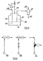
- a pump 1 for delivering a liquid 2 (a solvent or reagent, for instance) into a carrier stream comprises a reservoir in the form of a bottle 3 fitted with a screw-cap 4 through which pass tubes 5 and 6.
- Tube 5 provides an inlet for a gas
- tube 6 provides an outlet for the liquid 2.
- Both of the tubes 5 and 6 open near the bottom of bottle 1 and the open end of each is at the same level beneath the surface of the liquid.
- a capillary tube 7 also passes through the cap 4 and is connected to a capillary tube 10 (shown coiled but not necessarily coiled) open at its free end to provide a bleed line for the gas in the head space.
- the gas inlet tube 5 has a side arm which connects it with a pressure sensor 8 which is wired to a terminal 9 for connecting the sensor to the pump control circuit.
- Gas inlet tube 5 is provided with a connector 11 for connecting the tube to a drive gas control valve (optionally computer-controlled).
- Liquid outlet tube 6 has a connector 12 for connecting it through a valve (optionally computer-controlled) to a FIA manifold.
- Figure 2 shows schematically a control circuit for inlet of drive gas to the pump.
- the signal from pressure sensor 8 (preferably referenced to atmospheric pressure) is amplified at 13 and passed to a difference amplifier 14 together with a reference voltage signal from 15 amplified at 16.
- a difference amplifier 14 together with a reference voltage signal from 15 amplified at 16.
- the amplified signal from 14 is passed through a comparator 17 to a digital pulse generator 18 where together with a further signal (optionally computer generated) from 19 it controls the frequency and duration of pulse generation in accordance with the requirement to control the gas inlet pressure.
- a computer generated signal may not only control pulse duration but may also establish a voltage set point to which the pressure transducer is compared by 17 in order to define the required pressure of the inlet gas. Controlled in this way, the signal from pulse generator 18 passes to a valve driver 20 a signal containing information as to the pulse duration and pulse repetition needed to maintain or establish a desired condition within the pump.
- a FIA manifold comprising pumps as shown in Figure 1 is illustrated in Figure 3, in which 21a, 21b, 21c and 21d are solvent/reagent pumps, 22a, 22b and 22c are mixers, for example three-way valves, and 23 is a sampling system (described with reference to Figure 4).
- the manifold enables any number of solvent/reagent liquids to be mixed in any desired proportions with a sample or samples.
- Each of the solvent/reagent pumps is designed and controlled as described above to deliver a precise amount of liquid.
- the sampling system 23 is shown schematically in Figure 4 and consists of five interconnected three-way valves 25 to 29.
- Valve 25 is connected by line 31 with a source of a wash fluid and through line 32 with a source of a sample of the material to be analysed.
- Valve 25 is switchable to pass either the wash fluid or the sample to a second valve 26 which again is a three-way valve.
- Valve 26 enables wash fluid to be passed directly to drain or waste disposal in the direction of arrow 33 or sample to be passed towards the manifold system in the direction of arrow 34.
- Three-way valve 27 switches either the sample received from valve 26 or a (carrier) stream from line 37 to valve 28.
- valve 28 the sample can be switched either to the waste disposal line (arrow 35) or to the detector [arrow 36 - via a valve 29 and mixers 22b and 22c ( Figure 3)].
- Valve 29 completes the sampling system and as shown enables a (carrier) stream from line 37 to pass directly to the detector (via mixers 22b and 22c) or the (carrier) stream can be switched into the sample line via valve 27.
- valves 25 and 26 are operated to allow sample to flow to line 34 and valves 27 and 28 allow flow to line 35.
- Valve 29 prevents flow of carrier to the detector.
- sample passes through valves 25, 26, 27 and 28 to waste and the flow of carrier fluid is cut off.
- Valve 28 is operated to allow sample to pass to valve 29 and the detector line and at the same time valve 27 is operated to stop the flow of sample from line 34 and pass a (carrier) stream from line 37 so that carrier drives the sample located between valves 27 and 28 to the detector line via valve 29.
- slugs of sample can be passed to the detector.
- sample flows through valves 25, 26, 27 and 28 to waste, whilst carrier fluid flows through valve 29 to the detector line. If at the same time valves 27, 28 and 29 are switched then the sample flow from line 34 is cut off and a slug of sample (i.e. that located between valves 27 and 28) is driven through the detector line by carrier fluid.
- a slug of sample i.e. that located between valves 27 and 28
- valves 25 and 26 may be operated to purge the sample directly to waste, whilst valves 27 and 28 allow carrier fluid to pass either to waste or to the detector line.
- valves 25, 26, 27 and 28 are operated to allow washing fluid to pass through the lines between valves 26, 27 and 28 to waste or to the detector via valve 29.
- valve change sequences to perform the various operational functions can be programmed into a computer so that a predetermined programme of analyses can be carried out automatically.
- a system of the latter type may comprise, for example, a manifold system as shown in Figure 3 having a pressure reduction unit connected after the detector 24, a suitable pressure reduction unit being illustrated in Figure 5.
- the pressure reduction unit or vacuum control unit 38 comprises a pressure rated vessel 39 into which waste fluid from the detector (24) is drawn through line 40 into a constant head of liquid 41.
- a line 42 connects vessel 39 to an ejector device 43 in which the flow of a gas or liquid via inlet 44 and outlet 45 (to drain, for instance) creates a suction on line 42 and draws fluid from vessel 39.
- the reduced pressure thereby created in vessel 39 in turn draws fluid from the detector through line 40 and in fact draws fluid through the entire manifold system.
- the magnitude of the reduced pressure effected in this way is controlled by allowing the controlled influx of gas, e.g.
- a pressure sensor/control unit 48 monitors the reduced pressure relative to that of the gas source (ambient) and releases pulses of gas into vessel 39 using a control circuit similar to that illustrated in Figure 2.
- the reduced pressure unit may be located after the detector 24 in the manifold system of Figure 3 so as to draw fluids through that manifold instead of driving the fluids through using a pressurised gas source.
- the reduced pressure unit can advantageously be added to the manifold system to supplement rather than replace the positive drive facility. In this way, a greater pressure differential can be provided across the manifold without exceeding the pressure rating of the pressurised vessels.
- a faster throughput of fluids may be achieved and the system is better equipped to handle viscous fluids which may be encountered as samples and/or reagents.
- the sample and/or reagent pumps may be simpler devices operating on the mariot principle. It will be appreciated also that in the draw-through system there is no requirement for a pressurised gas source; this makes the system more attractive for transport for field uses, for example.
- the manifold system shown in and described with reference to Figure 3 comprises mixers 22a, 22b and 22c and three types of mixers which may be utilised are represented as Figures 6a, 6b and 6c in Figure 6.
- the member denoted as 1 is a pump essentially as shown in Figure 1.
- the device shown in Figure 6a is for continous delivery of one fluid (from the pump) into another fluid stream.
- any of the mixers 22a, 22b and 22c may have this configuration.
- further mixers may be provided as shown in broken lines in the drawing.
- Figure 6b shows a mixer comprising a two-way valve which allows intermittent addition of one fluid (from the pump) into another fluid stream. Pulse-free delivery of fluid from the pump and repeated operation at high frequency (typically 1Hz - 100Hz) of the two-way ratioing valve ensures effective mixing of the two fluid streams.
- the valve may be operated with any desired mark space ratio.
- Optional additional mixers may be provided as shown in broken lines in the drawing.
- the ratioing valve is preferably a low dead-volume three-way valve such as is shown in Figure 6c.
- An optional additional mixer may be provided as shown in broken lines in the drawing.
- the fluid mixing ratio is determined solely by the relative pressures of the fluid streams being mixed.
- the valve introduces a further control over the mixing ratio since in this case the valve timing as well as the fluid pressure influences delivery of the fluid.
- the mixing operation at each point in the manifold system can be controlled by computer in order to ensure precise and repeatable blending of fluid streams even when sampling procedures are undertaken.
- Figure 7 Some safety features which it is desirable to build into the pump and its control system are illustrated in Figure 7. As shown in this Figure, the system is modified by incorporation of an additional pressure sensor and a pressure relief valve.
- the gas inlet tube 5 is connected to a gas inlet valve 48 in advance of which is provided a side arm to a pressure sensor 49.
- the signal 50 from pressure sensor 49 is compared with the signal from pressure sensor 8.
- the pressure sensed at sensor 49 should always be greater than that sensed at sensor 8.
- the gas bleed tube 7 is connected through a relief valve 51 to a vent line.
- a pressure relief valve say 10 psig - 68 kPa
- a capillary restrictor in the gas supply line.
- a pump body e.g. a plastic-coated glass bottle or a plastic bottle, designed to withstand a much greater internal pressure than is ever likely to be encountered in normal usage of the pump.
Landscapes
- Physics & Mathematics (AREA)
- Chemical & Material Sciences (AREA)
- Analytical Chemistry (AREA)
- Fluid Mechanics (AREA)
- General Physics & Mathematics (AREA)
- Health & Medical Sciences (AREA)
- Clinical Laboratory Science (AREA)
- Automation & Control Theory (AREA)
- Engineering & Computer Science (AREA)
- Chemical Kinetics & Catalysis (AREA)
- Life Sciences & Earth Sciences (AREA)
- Biochemistry (AREA)
- General Health & Medical Sciences (AREA)
- Immunology (AREA)
- Pathology (AREA)
- Automatic Analysis And Handling Materials Therefor (AREA)
- Sampling And Sample Adjustment (AREA)
- Jet Pumps And Other Pumps (AREA)
Description
- This invention relates to flow injection analysis and particularly to an improved flow injection analysis system having the capability of performing analyses with improved precision and repeatability and being programmable for control by a computer. A particular feature of the system is a novel sample preparation pump which is useful in applications other than flow injection analysis, for example calibration, optimisation and detector characterisation and as part of a small-scale reactor system.
- Flow injection analysis (FIA) is a versatile technique available to the analyst for carrying out analyses of fluids, especially liquids. In essence, the technique comprises mixing a sample of a fluid to be analysed with one or more reagents which react with the sample in a carrier whilst travelling to a detector which responds to any changes induced by the reaction. The system may be operated by injecting a sample into a carrier stream containing the reactant(s) (normal FIA) or by injecting reactant(s) into a carrier stream containing the sample (inverse FIA). The system permits accurate control over the time interval between injection of the sample or reagent and the detector, thereby allowing reaction products to be detected without waiting for a steady-state to be reached, so allowing rapid sampling and enabling reactions to be used which do not go to completion in the permitted time interval before detection. A typical instrument for carrying out FIA comprises a pump for pumping the carrier, a sample injector, optionally a coil providing the required residence time for reaction and a detector.
- Known forms of pump for these purposes include peristaltic pumps and bottle-like reservoirs from which liquid is displaced by introducing gas under pressure to the ullage therein from a gas source by way of a regulator valve. Such regulator valves are not particularly accurate and do nothing to compensate for the changing head of liquid in the reservoir above the liquid outlet.
- The present invention resides in the discovery that improved results are obtained in FIA systems by providing a steadier flow of fluid than is obtainable using previously used pumps. The improved fluid handling system is reliable and can be (and preferably is) made even more reliable and precise by being designed for use with computer control giving flexibly programmable apparatus.
- DE-A-2144240 discloses a liquid pump comprising a reservoir, an outlet tube for conducting liquid from the reservoir and an inlet tube for introducing gas into the liquid in the reservoir to displace liquid therefrom through the outlet tube.
- According to the present invention there is provided a liquid pump comprising a reservoir, an outlet tube for conducting liquid from the reservoir and an inlet tube for introducing gas into the liquid in the reservoir to displace liquid therefrom through said outlet tube, characterised by means in the inlet tube for producing an electrical output signal which varies in dependence upon the pressure head in the liquid pump and means for making a comparison between said output signal and an electrical reference signal and means for utilising the comparison to control the feed of gas through the inlet tube into the reservoir.
- The gas may be fed into the liquid at a fixed level therein relative to the entrance to the outlet tube and such as to maintain a constant pressure at that level.
- The gas may be introduced above ambient pressure, or drawn in by suction applied to the outlet tube.
- The fixed level may be at or adjacent said entrance.
- In this way, the pressure in the liquid expelled from the bottle remains constant, thereby ensuring that the liquid flow is constant.
- The pressurising gas may be fed into the reservoir in the form of a series of precisely controlled rapid pulses of gas. The pulse duration may be variable depending upon the desired rate of flow of liquid; by way of example the pulse duration may be say 2 milliseconds for a low liquid flow rate and up to 20 milliseconds for a high liquid flow rate. It will be appreciated that these figures relate to standard type FIA devices and may be different for another size of device. The pulse repetition frequency may be controllable up to about 200 Hz but in general will be set at a maximum of about 20 Hz in order to conserve valve lifetime.
- Thus pulse duration and pulse repetition frequency may be controlled thereby providing control of solvent/reagent flow rates and amount of solvent/reagent delivered. In a standard device, flow rates of up to about 5 ml/minute are typical; higher flow rates are possible using reservoirs designed to withstand higher internal pressures.
- The pressure of the gas at the end of the gas inlet tube can be sensed, optionally in a computer-controlled device, and compared with a reference signal (eg computer generated) which is related to atmospheric pressure. Pressure sensing may be, for example, by a piezoresistive differential pressure sensor. Any difference between the measured pressure and the reference signal is used to vary the gas flow rate by changing either or both of the pulse duration and the pulse repetition frequency, these being changed by alteration of the timing of the gas release valve. Using this pressure control technique, the pressure difference between the drive gas and the ambient atmosphere is maintained regardless of any fluctuations in ambient pressure (and, within reason, gas pressure) and/or solvent/reagent demand. This constancy of pressure difference is especially valuable in cases where a valve is introduced after the pump to stop or switch the liquid flow.
- As indicated above, the device can be operated at high or low solvent/reagent flow rates. In the case of low solvent/reagent flow rates in particular a gas bleed may be provided in the system. A gas bleed line may be connected to the head space to permit a slow escape of gas from the head and ensure better control of the drive gas pressure and hence the liquid flow rate.
- The system is not restricted to a single sample or reagent pump and indeed several pumps, each of the improved design described hereinbefore, may be provided. The system thus has the capability of mixing a single sample with one or several reagents, several samples with a single reagent or more than one sample with more than one reagent.
- The improved FIA system of the invention affords a number of advantages over the conventional system using prior known pumps. The system provides a pulseless, jitter-free delivery of solvent/reagent at a smooth, controlled flow rate. There is no backlash at start/stop of liquid flow downstream of the solvent/reagent pump(s) and an instant start is achieved in stopped-flow experiments. Since the pressurising gas is introduced into the body of the solvent/reagent it serves to purge or de-gas the solvent/reagent as it rises to the head space, thereby avoiding air bubbles in the solvent/reagent. For effective purging and/or de-gassing of the liquid, we have used helium with good results. The pump system and indeed the entire device can be constructed of materials which are inert to the solvent and/or the reagent so that the need for replacement of consumable parts (such as the elastomer tubing of peristaltic pumps) is obviated.
- The system affords an active feedback control of the pressure head in the pump and a high tolerance of changes in ambient pressure and drive gas pressure. The system compensates for changes in the liquid (solvent/ reagent) level in the pump as solvent/reagent is consumed, thereby obviating the need for maintaining a constant liquid level. There is no need for high quality gas regulators, although a good quality low pressure relief valve followed by a capillary restrictor is advisable for safety. The pump can deliver very low solvent/reagent flow rates reproducibly and precisely.
- The detector of the FIA system may be any of those usually used in FIA devices, for example a spectrophotometer, a liquid chromatograph, an electrochemical sensor or an atomic spectroscope.
- The liquid pump may be used with an FIA manifold including a sampling section comprising a length of line between valve means at its opposite ends, the valve means being operable firstly to enable the filling of said length with sample and secondly its expulsion into a carrier stream.
- The FIA manifold may include a line for carrying one fluid via valve means for mixing with another fluid flowing through another line, there being means to open and close the valve means repeatedly at high frequency to ensure rapid intimate mixing of the two fluids.
- The invention will now be illustrated by way of example only with reference to the accompanying drawings, in which:-
- Figure 1
- shows a solvent/reagent pump,
- Figure 2
- shows a schematic representation of a control circuit for the pump of Figure 1,
- Figure 3
- is a schematic representation of an FIA manifold in which each element of the system is under the control of a computer,
- Figure 4
- is a schematic representation of a system of three-way valves in one example of a sampling arrangement,
- Figure 5
- shows a pressure reduction unit suitable for drawing fluids through the manifold system shown in Figure 3,
- Figure 6
- shows three types of mixers which can be used in the manifold system of Figure 3, and
- Figure 7
- shows the pump of Figure 1 provided with various safety features.
- Referring firstly to Figure 1, a
pump 1 for delivering a liquid 2 (a solvent or reagent, for instance) into a carrier stream comprises a reservoir in the form of abottle 3 fitted with a screw-cap 4 through whichpass tubes 5 and 6. Tube 5 provides an inlet for a gas and tube 6 provides an outlet for theliquid 2. Both of thetubes 5 and 6 open near the bottom ofbottle 1 and the open end of each is at the same level beneath the surface of the liquid. - Although in the pump shown in Figure 1 the
gas inlet tube 5 and the liquid outlet tube 6 open at the same level in the liquid, it will be appreciated that this is only a preferred design and that the opening of the tubes may be at different levels within the liquid provided that the difference in levels remains constant. - A capillary tube 7 also passes through the
cap 4 and is connected to a capillary tube 10 (shown coiled but not necessarily coiled) open at its free end to provide a bleed line for the gas in the head space. - The
gas inlet tube 5 has a side arm which connects it with apressure sensor 8 which is wired to aterminal 9 for connecting the sensor to the pump control circuit.Gas inlet tube 5 is provided with aconnector 11 for connecting the tube to a drive gas control valve (optionally computer-controlled). Liquid outlet tube 6 has aconnector 12 for connecting it through a valve (optionally computer-controlled) to a FIA manifold. - Figure 2 shows schematically a control circuit for inlet of drive gas to the pump. The signal from pressure sensor 8 (preferably referenced to atmospheric pressure) is amplified at 13 and passed to a
difference amplifier 14 together with a reference voltage signal from 15 amplified at 16. It will be appreciated that various electronic configurations may be utilised to enhance the stability of the reference signal. In the embodiment shown in Figure 2, the amplified signal from 14 is passed through acomparator 17 to adigital pulse generator 18 where together with a further signal (optionally computer generated) from 19 it controls the frequency and duration of pulse generation in accordance with the requirement to control the gas inlet pressure. For example a computer generated signal may not only control pulse duration but may also establish a voltage set point to which the pressure transducer is compared by 17 in order to define the required pressure of the inlet gas. Controlled in this way, the signal frompulse generator 18 passes to a valve driver 20 a signal containing information as to the pulse duration and pulse repetition needed to maintain or establish a desired condition within the pump. - A FIA manifold comprising pumps as shown in Figure 1 is illustrated in Figure 3, in which 21a, 21b, 21c and 21d are solvent/reagent pumps, 22a, 22b and 22c are mixers, for example three-way valves, and 23 is a sampling system (described with reference to Figure 4). A
detector 24, for example a spectrophotometer, connects with the manifold. As will be apparent, in principle the manifold enables any number of solvent/reagent liquids to be mixed in any desired proportions with a sample or samples. Each of the solvent/reagent pumps is designed and controlled as described above to deliver a precise amount of liquid. - The
sampling system 23 is shown schematically in Figure 4 and consists of five interconnected three-way valves 25 to 29.Valve 25 is connected by line 31 with a source of a wash fluid and throughline 32 with a source of a sample of the material to be analysed.Valve 25 is switchable to pass either the wash fluid or the sample to asecond valve 26 which again is a three-way valve.Valve 26 enables wash fluid to be passed directly to drain or waste disposal in the direction ofarrow 33 or sample to be passed towards the manifold system in the direction of arrow 34. Three-way valve 27 switches either the sample received fromvalve 26 or a (carrier) stream from line 37 tovalve 28. Atvalve 28 the sample can be switched either to the waste disposal line (arrow 35) or to the detector [arrow 36 - via avalve 29 andmixers 22b and 22c (Figure 3)].Valve 29 completes the sampling system and as shown enables a (carrier) stream from line 37 to pass directly to the detector (viamixers 22b and 22c) or the (carrier) stream can be switched into the sample line viavalve 27. - Operation of the sampling system is as follows. For stopped-flow sampling, i.e. where the flow of fluid to the detector is intermittent,
valves valves Valve 29 prevents flow of carrier to the detector. In this arrangement, sample passes throughvalves Valve 28 is operated to allow sample to pass tovalve 29 and the detector line and at thesame time valve 27 is operated to stop the flow of sample from line 34 and pass a (carrier) stream from line 37 so that carrier drives the sample located betweenvalves valve 29. Thus slugs of sample can be passed to the detector. - For continuous-flow sampling, i.e. where there is a continuous flow of fluid to the detector, sample flows through
valves valve 29 to the detector line. If at thesame time valves valves 27 and 28) is driven through the detector line by carrier fluid. Thus, there is a continuous flow of fluid through the detector line whilst slugs of sample are entrained as desired. - To purge the system of sample,
valves valves - To wash out the sampling system,
valves valves valve 29. - It will be appreciated that the various valve change sequences to perform the various operational functions can be programmed into a computer so that a predetermined programme of analyses can be carried out automatically.
- In the manifold system described with reference to Figures 3 and 4 the fluids (wash, sample, carrier or reagent fluids) are driven through under positive drive gas pressure but it will be appreciated that instead the fluids may be drawn through the system by reduced pressure. A system of the latter type may comprise, for example, a manifold system as shown in Figure 3 having a pressure reduction unit connected after the
detector 24, a suitable pressure reduction unit being illustrated in Figure 5. - Referring to Figure 5, the pressure reduction unit or
vacuum control unit 38 comprises a pressure ratedvessel 39 into which waste fluid from the detector (24) is drawn throughline 40 into a constant head ofliquid 41. Aline 42 connectsvessel 39 to anejector device 43 in which the flow of a gas or liquid viainlet 44 and outlet 45 (to drain, for instance) creates a suction online 42 and draws fluid fromvessel 39. The reduced pressure thereby created invessel 39 in turn draws fluid from the detector throughline 40 and in fact draws fluid through the entire manifold system. The magnitude of the reduced pressure effected in this way is controlled by allowing the controlled influx of gas, e.g. ambient air, intovessel 39 through aline 46 via acontrol valve 47 such as a three-way valve of the fail-to-open type.Valve 47 is controlled in the same way as is described hereinbefore for the positive pressure drive gas valves of the pump shown in Figure 1. A pressure sensor/control unit 48 monitors the reduced pressure relative to that of the gas source (ambient) and releases pulses of gas intovessel 39 using a control circuit similar to that illustrated in Figure 2. - As described, the reduced pressure unit may be located after the
detector 24 in the manifold system of Figure 3 so as to draw fluids through that manifold instead of driving the fluids through using a pressurised gas source. Alternatively, the reduced pressure unit can advantageously be added to the manifold system to supplement rather than replace the positive drive facility. In this way, a greater pressure differential can be provided across the manifold without exceeding the pressure rating of the pressurised vessels. Thus, for instance, a faster throughput of fluids may be achieved and the system is better equipped to handle viscous fluids which may be encountered as samples and/or reagents. - It will be appreciated that in the manifold equipped with a reduced pressure unit, the sample and/or reagent pumps may be simpler devices operating on the mariot principle. It will be appreciated also that in the draw-through system there is no requirement for a pressurised gas source; this makes the system more attractive for transport for field uses, for example.
- The manifold system shown in and described with reference to Figure 3 comprises
mixers - The device shown in Figure 6a is for continous delivery of one fluid (from the pump) into another fluid stream. Thus with reference to Figure 3 any of the
mixers - Figure 6b shows a mixer comprising a two-way valve which allows intermittent addition of one fluid (from the pump) into another fluid stream. Pulse-free delivery of fluid from the pump and repeated operation at high frequency (typically 1Hz - 100Hz) of the two-way ratioing valve ensures effective mixing of the two fluid streams. The valve may be operated with any desired mark space ratio. Optional additional mixers may be provided as shown in broken lines in the drawing.
- The ratioing valve is preferably a low dead-volume three-way valve such as is shown in Figure 6c. An optional additional mixer may be provided as shown in broken lines in the drawing.
- In the arrangement of Figure 6a the fluid mixing ratio is determined solely by the relative pressures of the fluid streams being mixed. In the arrangements shown in Figures 6b and 6c, however, the valve introduces a further control over the mixing ratio since in this case the valve timing as well as the fluid pressure influences delivery of the fluid.
- Irrespective of the type of mixing device employed it is preferred that the mixing operation at each point in the manifold system can be controlled by computer in order to ensure precise and repeatable blending of fluid streams even when sampling procedures are undertaken.
- Some safety features which it is desirable to build into the pump and its control system are illustrated in Figure 7. As shown in this Figure, the system is modified by incorporation of an additional pressure sensor and a pressure relief valve. The
gas inlet tube 5 is connected to agas inlet valve 48 in advance of which is provided a side arm to apressure sensor 49. Thesignal 50 frompressure sensor 49 is compared with the signal frompressure sensor 8. The pressure sensed atsensor 49 should always be greater than that sensed atsensor 8. The gas bleed tube 7 is connected through arelief valve 51 to a vent line. - These features are designed to cater for situations where there is a failure of the gas supply which otherwise could result in damage due to the drawing of liquid from the pump back into the
pressure sensor 8 or even into thegas supply valve 48 and the source of the gas. In the modified system of Figure 7, in the event of a failure of the gas supply or of it being inadvertently turned off, the gas pressure in the headspace of the pump exceeds that in the gas supply throughvalve 48. Thepressure sensor 49 measures the pressure of the gas supply tovalve 48 and compares it with the headspace pressure measured bysensor 8. A dedicated electronic circuit controls therelief valve 51 such that it is opened thereby venting the headspace within the pump. The system can be set up so that further operation of the pump is halted until the fault has been corrected and thevalve 51 has been reset. In the event of a power failure,gas supply valve 48 is closed to shut off the gas source andvalve 51 is opened to vent the pump headspace. - Other safety features (not illustrated) which are desirable are a pressure relief valve (say 10 psig - 68 kPa) in the gas supply line and a capillary restrictor in the gas supply line. Also it is advisable to employ a pump body, e.g. a plastic-coated glass bottle or a plastic bottle, designed to withstand a much greater internal pressure than is ever likely to be encountered in normal usage of the pump.
Claims (9)
- A liquid pump comprising a reservoir (3), an outlet tube (6) for conducting liquid from the reservoir and an inlet tube (5) for introducing gas into the liquid (2) in the reservoir to displace liquid therefrom through said outlet tube, characterised by means (8) for producing an electrical output signal which varies in dependence upon the pressure head in the liquid pump and means (17) for making a comparison between said output signal and an electrical reference signal and means (18, 20) for utilising the comparison to control the feed of gas through the inlet tube into the reservoir.
- A liquid pump according to claim 2, further comprising means (18,20) for introducing the gas into the reservoir in the form of a series of pulses controlled by said utilising means.
- A liquid pump according to claim 1, further comprising means for feeding gas into the liquid from said inlet tube at a fixed level therein relative to an entrance to said outlet tube and such as to maintain a constant gas pressure at said fixed level.
- A liquid pump according to claim 3, wherein the fixed level is at or adjacent said entrance to the outlet tube.
- A liquid pump according to claim 1, further comprising means for introducing gas into said reservoir at a pressure above ambient pressure.
- A liquid pump according to claim 1, further comprising means for introducing gas into said reservoir by the application of suction to said outlet tube.
- A liquid pump according to claim 1, including a gas bleed line (10) from a location above the liquid in said reservoir.
- A liquid pump according to claim 2, wherein the pulses are of fixed frequency and variable duration.
- A liquid pump according to claim 2, wherein the pulses are of fixed duration and variable frequency.
Applications Claiming Priority (2)
| Application Number | Priority Date | Filing Date | Title |
|---|---|---|---|
| GB8817456 | 1988-07-22 | ||
| GB888817456A GB8817456D0 (en) | 1988-07-22 | 1988-07-22 | Flow injection analysis |
Publications (3)
| Publication Number | Publication Date |
|---|---|
| EP0351995A2 EP0351995A2 (en) | 1990-01-24 |
| EP0351995A3 EP0351995A3 (en) | 1991-01-16 |
| EP0351995B1 true EP0351995B1 (en) | 1993-03-31 |
Family
ID=10640912
Family Applications (1)
| Application Number | Title | Priority Date | Filing Date |
|---|---|---|---|
| EP89306972A Expired - Lifetime EP0351995B1 (en) | 1988-07-22 | 1989-07-10 | Flow injection analysis |
Country Status (5)
| Country | Link |
|---|---|
| US (1) | US5156814A (en) |
| EP (1) | EP0351995B1 (en) |
| JP (1) | JPH02154154A (en) |
| DE (1) | DE68905698T2 (en) |
| GB (1) | GB8817456D0 (en) |
Cited By (1)
| Publication number | Priority date | Publication date | Assignee | Title |
|---|---|---|---|---|
| US7427379B1 (en) | 1999-03-19 | 2008-09-23 | Biotage Ab | Liquid dispensing apparatus |
Families Citing this family (13)
| Publication number | Priority date | Publication date | Assignee | Title |
|---|---|---|---|---|
| GB9021094D0 (en) * | 1990-09-27 | 1990-11-07 | Oxford Glycosystems Ltd | Liquid delivery systems |
| JPH08501496A (en) * | 1993-07-09 | 1996-02-20 | マイクロスキャン、インコーポレイテッド | Precision liquid dispensing device and method |
| US5487313A (en) * | 1993-11-30 | 1996-01-30 | Microsensor Technology, Inc. | Fluid-lock fixed-volume injector |
| FR2713362B1 (en) * | 1993-12-03 | 1996-03-01 | Helispire Sarl | Device for metering a fluid in a controlled manner. |
| US6244826B1 (en) * | 1995-10-10 | 2001-06-12 | T. R. Sarathi | Gaseous piston method for suction and compression in closed chamber gas equipments |
| US5671603A (en) * | 1995-12-08 | 1997-09-30 | The Perkin-Elmer Corporation | Apparatus for controlling level of cryogenic liquid |
| US6240942B1 (en) | 1999-05-13 | 2001-06-05 | Micron Technology, Inc. | Method for conserving a resource by flow interruption |
| US6899114B2 (en) * | 2001-08-22 | 2005-05-31 | Paul A. Wilson | Device for the dilution and application of liquids |
| GB0218946D0 (en) | 2002-08-14 | 2002-09-25 | Thermo Electron Corp | Diluting a sample |
| US8465697B2 (en) * | 2007-12-31 | 2013-06-18 | O.I. Corporation | System and method for regulating flow in fluidic devices |
| DE102009001612B9 (en) * | 2009-03-17 | 2012-03-08 | Si Analytics Gmbh | Method and apparatus for generating constant pulsation-free fluid streams for microfluidic applications |
| US20170313296A1 (en) * | 2016-04-28 | 2017-11-02 | Chuan Jiing Enterprise Co., Ltd. | Brake fluid feeding device |
| EP3376182A1 (en) * | 2017-03-14 | 2018-09-19 | CSEM Centre Suisse D'electronique Et De Microtechnique SA | Fluid dispensing system and method |
Family Cites Families (7)
| Publication number | Priority date | Publication date | Assignee | Title |
|---|---|---|---|---|
| US3749113A (en) * | 1970-09-14 | 1973-07-31 | Technician Instr Corp | Flow regulator for controlling ultra-low volumetric flow rates |
| US4683212A (en) * | 1982-09-30 | 1987-07-28 | Technicon Instruments Corporation | Random access single channel sheath stream apparatus |
| US4740356A (en) * | 1983-06-10 | 1988-04-26 | The Perkin-Elmer Corporation | Device for producing a gaseous measuring sample for atomic absorption spectroscopy |
| US4567748A (en) * | 1984-07-19 | 1986-02-04 | Klass Carl S | On-line linear tonometer |
| JPS6280301A (en) * | 1985-10-03 | 1987-04-13 | Yamatake Honeywell Co Ltd | Electro-pneumatic transducer |
| EP0273934B1 (en) * | 1986-07-01 | 1990-09-05 | Biotech Instruments Limited | Apparatus for automatic chemical analysis |
| US5098657A (en) * | 1989-08-07 | 1992-03-24 | Tsi Incorporated | Apparatus for measuring impurity concentrations in a liquid |
-
1988
- 1988-07-22 GB GB888817456A patent/GB8817456D0/en active Pending
-
1989
- 1989-07-10 DE DE8989306972T patent/DE68905698T2/en not_active Expired - Fee Related
- 1989-07-10 EP EP89306972A patent/EP0351995B1/en not_active Expired - Lifetime
- 1989-07-21 JP JP1190366A patent/JPH02154154A/en active Pending
-
1990
- 1990-12-03 US US07/622,491 patent/US5156814A/en not_active Expired - Fee Related
Cited By (1)
| Publication number | Priority date | Publication date | Assignee | Title |
|---|---|---|---|---|
| US7427379B1 (en) | 1999-03-19 | 2008-09-23 | Biotage Ab | Liquid dispensing apparatus |
Also Published As
| Publication number | Publication date |
|---|---|
| US5156814A (en) | 1992-10-20 |
| EP0351995A3 (en) | 1991-01-16 |
| DE68905698T2 (en) | 1993-07-08 |
| GB8817456D0 (en) | 1988-08-24 |
| JPH02154154A (en) | 1990-06-13 |
| EP0351995A2 (en) | 1990-01-24 |
| DE68905698D1 (en) | 1993-05-06 |
Similar Documents
| Publication | Publication Date | Title |
|---|---|---|
| EP0351995B1 (en) | Flow injection analysis | |
| EP0048917B1 (en) | A method and apparatus for volumetrically controlled and reproducible introduction of small amounts of liquid samples into chromatographic analysis systems | |
| EP1334770B1 (en) | Precision liquid dispensing system | |
| US6112605A (en) | Method for dispensing and determining a microvolume of sample liquid | |
| EP0022654B1 (en) | Liquid handling device | |
| US3756459A (en) | Method and apparatus for metering fluid utilizing pressure differentials | |
| US4865811A (en) | Apparatus for automatic chemical analysis | |
| KR950033481A (en) | Liquid Chromatograph with Micro- or Semi-Micro Column | |
| US20110045599A1 (en) | System and Method for Regulating Flow in Fluidic Devices | |
| US7484399B2 (en) | System, apparatus and method for dispensing chemical vapor | |
| JP4622575B2 (en) | Bubble removal device | |
| EP1959259A2 (en) | Automatic analyzer | |
| US6475437B1 (en) | Method and system for preparing samples for gas chromatography | |
| US4896545A (en) | Automatic fluid injector | |
| EP0183950B1 (en) | Method of processing liquid within a tube | |
| US4442217A (en) | Sample injection | |
| JPWO2007023889A1 (en) | Flow analysis system | |
| Sweileh et al. | Novel automated micro batch analyzer | |
| JP4618001B2 (en) | Automatic chemical analyzer | |
| GB2192278A (en) | Apparatus for and method of flow injection analysis | |
| KR100231298B1 (en) | Bubble detector for hplc system | |
| US20040223887A1 (en) | Degassification of fluids | |
| KR970017913A (en) | Supply device for chemical solution for semiconductor device manufacturing | |
| JPH0429414Y2 (en) | ||
| GB2055608A (en) | Sample injection |
Legal Events
| Date | Code | Title | Description |
|---|---|---|---|
| PUAI | Public reference made under article 153(3) epc to a published international application that has entered the european phase |
Free format text: ORIGINAL CODE: 0009012 |
|
| AK | Designated contracting states |
Kind code of ref document: A2 Designated state(s): DE FR GB |
|
| PUAL | Search report despatched |
Free format text: ORIGINAL CODE: 0009013 |
|
| AK | Designated contracting states |
Kind code of ref document: A3 Designated state(s): DE FR GB |
|
| 17P | Request for examination filed |
Effective date: 19910320 |
|
| 17Q | First examination report despatched |
Effective date: 19920518 |
|
| GRAA | (expected) grant |
Free format text: ORIGINAL CODE: 0009210 |
|
| AK | Designated contracting states |
Kind code of ref document: B1 Designated state(s): DE FR GB |
|
| REF | Corresponds to: |
Ref document number: 68905698 Country of ref document: DE Date of ref document: 19930506 |
|
| ET | Fr: translation filed | ||
| PLBE | No opposition filed within time limit |
Free format text: ORIGINAL CODE: 0009261 |
|
| STAA | Information on the status of an ep patent application or granted ep patent |
Free format text: STATUS: NO OPPOSITION FILED WITHIN TIME LIMIT |
|
| 26N | No opposition filed | ||
| PGFP | Annual fee paid to national office [announced via postgrant information from national office to epo] |
Ref country code: FR Payment date: 19980611 Year of fee payment: 10 |
|
| PGFP | Annual fee paid to national office [announced via postgrant information from national office to epo] |
Ref country code: GB Payment date: 19980623 Year of fee payment: 10 |
|
| PGFP | Annual fee paid to national office [announced via postgrant information from national office to epo] |
Ref country code: DE Payment date: 19980629 Year of fee payment: 10 |
|
| PG25 | Lapsed in a contracting state [announced via postgrant information from national office to epo] |
Ref country code: GB Free format text: LAPSE BECAUSE OF NON-PAYMENT OF DUE FEES Effective date: 19990710 |
|
| PG25 | Lapsed in a contracting state [announced via postgrant information from national office to epo] |
Ref country code: FR Free format text: THE PATENT HAS BEEN ANNULLED BY A DECISION OF A NATIONAL AUTHORITY Effective date: 19990731 |
|
| GBPC | Gb: european patent ceased through non-payment of renewal fee |
Effective date: 19990710 |
|
| PG25 | Lapsed in a contracting state [announced via postgrant information from national office to epo] |
Ref country code: DE Free format text: LAPSE BECAUSE OF NON-PAYMENT OF DUE FEES Effective date: 20000503 |
|
| REG | Reference to a national code |
Ref country code: FR Ref legal event code: ST |