EP0350978A1 - Method for determining drilling conditions while drilling - Google Patents
Method for determining drilling conditions while drilling Download PDFInfo
- Publication number
- EP0350978A1 EP0350978A1 EP89201513A EP89201513A EP0350978A1 EP 0350978 A1 EP0350978 A1 EP 0350978A1 EP 89201513 A EP89201513 A EP 89201513A EP 89201513 A EP89201513 A EP 89201513A EP 0350978 A1 EP0350978 A1 EP 0350978A1
- Authority
- EP
- European Patent Office
- Prior art keywords
- torque
- formations
- bit
- drilling
- signal indicative
- Prior art date
- Legal status (The legal status is an assumption and is not a legal conclusion. Google has not performed a legal analysis and makes no representation as to the accuracy of the status listed.)
- Granted
Links
Images


Classifications
-
- E—FIXED CONSTRUCTIONS
- E21—EARTH DRILLING; MINING
- E21B—EARTH DRILLING, e.g. DEEP DRILLING; OBTAINING OIL, GAS, WATER, SOLUBLE OR MELTABLE MATERIALS OR A SLURRY OF MINERALS FROM WELLS
- E21B49/00—Testing the nature of borehole walls; Formation testing; Methods or apparatus for obtaining samples of soil or well fluids, specially adapted to earth drilling or wells
- E21B49/003—Testing the nature of borehole walls; Formation testing; Methods or apparatus for obtaining samples of soil or well fluids, specially adapted to earth drilling or wells by analysing drilling variables or conditions
-
- E—FIXED CONSTRUCTIONS
- E21—EARTH DRILLING; MINING
- E21B—EARTH DRILLING, e.g. DEEP DRILLING; OBTAINING OIL, GAS, WATER, SOLUBLE OR MELTABLE MATERIALS OR A SLURRY OF MINERALS FROM WELLS
- E21B44/00—Automatic control systems specially adapted for drilling operations, i.e. self-operating systems which function to carry out or modify a drilling operation without intervention of a human operator, e.g. computer-controlled drilling systems; Systems specially adapted for monitoring a plurality of drilling variables or conditions
Landscapes
- Geology (AREA)
- Life Sciences & Earth Sciences (AREA)
- Engineering & Computer Science (AREA)
- Mining & Mineral Resources (AREA)
- Environmental & Geological Engineering (AREA)
- Fluid Mechanics (AREA)
- Physics & Mathematics (AREA)
- General Life Sciences & Earth Sciences (AREA)
- Geochemistry & Mineralogy (AREA)
- Chemical & Material Sciences (AREA)
- Analytical Chemistry (AREA)
- Earth Drilling (AREA)
- Paper (AREA)
- Drilling And Boring (AREA)
Abstract
Description
- It is well known that oil field borehole evaluation may be performed by wireline conveyed instruments following the completion of the process of drilling a borehole. Such techniques have been available to the oil field industry for decades. Unfortunately, wireline investigation techniques are frequently disadvantageous due to their nature which requires that they be performed a substantial time after drilling and after the drill pipe has been removed from the borehole. Additionally, while the wireline techniques are effective in determining formation parameters, they are unable to provide insight into the borehole drilling process itself.
- In response to the shortcomings of wireline investigations, techniques which perform measurements while the borehole is being drilled are receiving greater acceptance by the oil field industry as standard, and indeed on occasion, indispensable services. Many such techniques differ from the traditional wireline techniques in that the MWD techniques are able to measure drilling parameters which not only provide information on the drilling process itself but also on the properties of the geological formations being drilled. Due to the relatively recent increased use of many MWD techniques, the oil field industry is still in the process of learning from experience how to most effectively utilize the new information that is becoming available from MWD. Perhaps not surprisingly, accumulating experience is revealing some rather unexpected results that may significantly improve the knowledge and efficiency of the process of forming boreholes in the earth.
- U.S. Patent 4,627,276, entitled Method For Measuring Bit Wear During Drilling by Burgess and Lesso, which is assigned to the assignee of the present invention and which is hereby incorporated by reference, proposed techniques for determining an index indicative of bit efficiency from surface and downhole derived drilling parameters. It also proposed techniques for generating an index indicative of the flatness of the teeth of the drill bit. These indices have proven invaluable in assisting in the drilling of a borehole since they enable the driller to determine in real time the condition of the bit and its efficiency in "making hole".
- Unfortunately, the described techniques, while encountering success in many downhole conditions, are less effective in some other downhole conditions. Specifically, the techniques described in the above mentioned patent function best in argillaceous (shaley) formations. Through additional experience gained by numerous applications of the techniques in the drilling of boreholes, the discovery has been made that it is not always evident to the driller whether the drill bit is in an argillaceous formation that is exhibiting changing properties as the bit advances through the formation or whether the bit is encountering a lithological change from the argillaceous formation to one in which the described technique is less effective, such as sandstone or limestone. A downhole MWD natural gamma ray instrument may be of assistance in distinguishing between sandstone and argillaceous lithologies. This information is not available in real time at the location of the bit however. Typically, MWD sensors are positioned in the drill string at some distance from the bit so that, while the natural gamma ray is frequently used to distinguish sands from shales, this ability only comes into effect at some time after the bit has penetrated the formation, which is frequently too late.
- It is, therefore, clearly desirable to identify the kind of formation being drilled, as it is being drilled, in order to enable the driller to determine whether the information derived by way of the prior art indexes of bit efficiency and dimensionless tooth flat adequately describe the current drilling conditions. It has not heretofore been evident how to distinguish between changing lithologies and a formation of the same lithology that is exhibiting a change in a "hardness" property.
- Additional techniques have now been discovered that address the task of distinguishing changing lithologies from a constant lithology exhibiting changing drillability properties. In the practice of the preferred embodiment of the present invention, a parameter designated "dimensionless torque" determined from downhole measurements made while drilling (MWD), is utilized to determine an indication of the drilling efficiency of the drill bit. Comparison of drilling efficiency with its running average enables the determination that the bit is drilling either an argillaceous formation or a tight or porus formation. When the formation being drilled is determined to be non-argillaceous, the last valid measurement of drilling efficiency in an argillaceous formation is utilized in further interpretation. Additionally, a parameter designated "dimensionless rate of penetration" is combined with a measure of downhole weight on bit to generate an indication of the resistance to penetration of the formation by the bit. The values of this "formation strength" parameter are then compared to a predetermined "formation strength" value in order to determine whether the bit is penetrating a porous formation or if it is experiencing either a tight formation or other cause of abnormal torque. Ambiguity is resolved by referring to the magnitude of the drilling efficiency parameter relative to the running average.
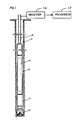
- Figure 1 is an illustration of an MWD apparatus in a drill string with a drill bit while drilling a borehole.
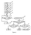
- Figure 2 is a block diagram of the interpretation functions performed on the drilling parameters generated from the apparatus of figure 1.
- Referring initially to figure 1, there is shown a drill string 10 suspended in a
borehole 11 and having a typical drill bit 12 (preferably of the insert bit type but alternatively of the PDC type) attached to its lower end. Immediately above thebit 12 is a sensor apparatus 13 for detection of downhole weight on bit (W) and downhole torque (T) constructed in accordance with the invention described in U.S. Patent 4,359,898 to Tanguy et al., which is incorporated herein by reference. The output of sensor 13 is fed to atransmitter assembly 15, for example, of the type shown and described in U.S. Patent 3,309,656, Godbey, which is also incorporated herein by reference. Thetransmitter 15 is located and attached within a specialdrill collar section 16 and functions to provide in the drilling fluid being circulated downwardly within the drill string 10 an acoustic signal that is modulated in accordance with sensed data. The signal is detected at the surface by a receivingsystem 17 and is processed by a processing means 14 to provide recordable data representative of the downhole measurements. Although an acoustic data transmission system is mentioned herein, other types of telemetry systems, of course, may be employed, provided they are capable of transmitting an intelligible signal from downhole to the surface during the drilling operation. - Reference is now made to Figure 2 for a detailed representation of a preferred embodiment of the present invention. Figure 2 illustrates the processing functions performed within the surface processing means 17. The downhole weight on bit (W) and downhole torque (T) signals derived from real time, in situ measurements made by MWD tool sensors 13 are delivered to the
processor 17. Also provided toprocessor 17 are surface determined values of rotary speed (RPM), Bit Size (D), and Rate of Penetration (R). In a broad sense,processor 17 responds to the rate of penetration and downhole torque inputs to detect the occurrence of changing lithology as distinguished from changes in the "toughness" of the formation rock as well as other effects such as bit wear, excess torque due to stabilizer gouging and cone locking. - While the present invention may be practiced by
programming processor 17 to respond merely to W, R and T, it has been found that improved results are obtained when R and T are converted into the normalized quantities "Dimensionless Rate of Penetration" (RD) and "Dimensionless Torque" (TD) respectively. This is performed inprocessor 17 as illustrated in figure 2 at 22, after the variables have first been initialized at 20, according to the following relationships:

- Returning to 24 of figure 2, once TD and RD have been obtained, they may be combined in any suitable manner in
processor 17 to obtain the coefficients (a₁, a₂) of a drilling equation, as is taught in US Patent 4,626,276, that expresses bit drilling efficiency ED as a function of dimensionless torque and dimensionless rate of penetration. Briefly, data points representative of TD and the root to the nth power (usually taken as the square root) of RD obtained at the beginning of a bit run when the bit is unworn, when plotted against each other define a straight line curve having a y axis intercept at a₁ and having a slope of a₂. Values of a₁ and a₂ are determined by the processor and are subsequently used in the analysis, for example in equation 3 above. - Having determined dimensionless torque, dimensionless rate of penetration, a₁, and a₂, the quantities known as the Dimensionless Efficiency (E), the Dimensionless Efficiency corrected or friction (ED), and the Dimensionless Efficiency Normalized for changes in weight on bit (EDn) may now be determined at 30 according to the following equations:
E = (TD - a₂√RD )/a₁ (4)
ED = [E - utan0]/[1 - utan0] (5)
EDn = [1 - (1 - ED)W]/Wnorm (6)
where u is the coefficient of friction between the rock being drilled and the teeth of the drill bit, 0 is the angle of attack of the teeth of the bit (tooth semiangle or roller cone bits or the rake angle for PDC bits), and Wnorm is the normal or recommended weight for the bit being used. As will be appreciated from the above relationships, E, ED, and EDn are primarily dependent on the downhole torque T. - Experience in the field with the parameter EDn has led to the discovery that when in an argillaceous formation, EDn, on average, varies slowly under normal drilling conditions as the bit wears. In non-argillaceous formations, EDn exhibits more erratic behavior. This observation enables one to monitor the behavior of EDn as an indication of whether the bit is drilling an argillaceous or a non-argillaceous formation. In general, this is done by generating a reference value indicative of argillaceous formation drilling. Preferably the reference value is one which is primarily dependent on torque (T) such as EDn. One may then compare a current value of EDn to the reference value in order to determine if the bit is currently drilling argillaceous formations. For example, the reference value may be the running average,

- Thus, at 32 a running average of values of EDn derived from argillaceous formations is obtained. The running average,


- Determination of argillaceous versus non-argillaceous formation is of significance not only for the drilling process but also for subsequent interpretation, since it has been discovered that the erratic behavior of EDn in non-argillaceous formations does not permit reliable determinations of the effects of bit wear. Accurate values of bit wear are essential in order to properly correct for the effects of the wear of the bit on the measured parameters such as downhole torque. It has therefore been found expedient, where it has been determined that the bit is drilling a non-argillaceous formation, to employ the last value of EDn when the bit was still drilling an argillaceous formation in order that the information be meaningful.
- If the comparison at 34 reveals that the current value of EDn is within the window formed about the running average of EDn, the current value may be used in a determination at 38 of "Flat" and "Fors" (herein appearing as F and FS respectively) which may generally be thought of as the degree of wear of the bit (F) and a measure of the resistance to penetration of the formation by the bit (FS) respectively. F and FS are determined according to the following relationships:
F = 8(1 - AEDn) (7)
FS = 40a₁W*RPM/R*D (8)
Where AEDn is the running average of EDn in argillaceous formations. The coefficient 8 is utilized here to correspond to the industry practice of grading a worn bit from 1 to 8 with 1 designating a new, unworn bit and 8 designating a bit that is completely worn out. - In figure 2
functional block 38 is implemented to derive indications of F and FS where the value of EDn falls within the high and low limits of the window placed around the running average of EDn. If EDn falls outside of this window, it is apparent that the bit is not drilling in an argillaceous formation (shale) or that a drilling problem is developing. - In order to further understand the nature of the events causing the normalized drilling efficiency to behave erratically, a current value of FS is determined at 36 from the last valid value of ED derived while EDn remained within the window around the running average of EDn from the following equation:
FS = ED[40a₁W*RPM/R*D]. (9) - Next it is determined at 44 whether EDn is above or below the the limits of the window around the running average of EDn. If above, the step of comparing the value of FS determined at 36 with an average shale strength is performed at 62. If FS turns out to be less than the average shale strength by forty percent, it may safely be concluded that the formation is a porous one.
- On the other hand, if FS is equal to or greater than the average shale strength, it is concluded that the readings are a result of a drilling condition other than lithology such as the generation of abnormal torque between the downhole measuring transducers and the drill bit such as a locked cone or a gouging stabilizer which may be related to an undergauge bit. The magnitude of the abnormal torque may be determined at 64 from the following relationship:
XSTQ = T - W*D(a₁ED * + a₂√RD ) (10)
where XSTQ is the abnormal (usually excess) torque below the MWD tool, and ED * is the last valid value of ED obtained while the bit is still in an argillaceous formation. - If the comparison in
decision element 44 shows that current values of EDn are below the limit of the window around the running average of EDn, it is next determined at 46 whether the current value FS is less than an average shale strength by forty percent. If so, it is concluded that the non-argillaceous formation being drilled is porous. If the comparison at 46 shows that the current value of FS is equal to or greater than the average shale strength, it is concluded that the non-argillaceous formation being drilled is one of low porosity or "tight". In either case a formation properties curve may be determined by dividing EDn by the average value of EDn. Such a curve, appearing in figure 5 can be drawn with a central band within which is an indication of argillaceous formations and outside of which is an indication of porous formations in the increasing and tight formations in the decreasing directions. - Turning now to Figure 3, 4, and 5 there are illustrated example logs that have been generated in connection with an application of the principles of the present invention. These figures shown the downhole measurement while drilling and surface derived data for a milled tooth bit run from a well drilling in the Gulf Coast region. An IADC series bit was used and the downhole instrument (MWD tool) was located above a single near bit stabilizer. The rotary speed over this bit run was maintained at approximately 140 rpm.
- From left to right in figure 3 there appear Rate of Penetration (28) plotted on a plot from 0 to 200 feet per hour, downhole weight on bit (40) plotted from 0 to 50 klbs, downhole torque (42) plotted from 0 to 5 k ftlbs and MWD resistivity (48) plotted from 0 to 2.0 ohm-meters which serves to help distinguish sand/shale sections. (Shale tends to have a higher resistivity than a water filled sand). In figure 4, also from left to right there appear dimensionless torque (TD) (52) plotted on a scale of 0 to .1 and formation strength (FS) (54) on a scale of 0 to 200 kpsi. Through the shale sections TD shows a gradual decrease over the bit run which is attributed to tooth wear. In the sandstone sections TD becomes erratic and tends to mask the wear trend of the bit.
- The formation strength curve clearly differentiates the sand/shale sections, the sandstones being the lower strength formations. Over the bit run the apparent strength of the shales increases from 20 to over 200 Kpsi, implying that the rock is harder to drill. However, this is more a function of the condition of the bit than the strength of the formation.
- Figure 5, left to right, there are shown logs of the following interpretation answer products: apparent efficiency (56) (normalized dimensionless drilling efficiency EDn) plotted from 0 to 2, tooth wear ("Flat", F) (58) plotted from 0 to 8, and a formation properties curve (60) based on the drilling action of the bit. This last, formation properties curve, is merely the apparent efficiency divided by a running average of the apparent efficiency. The apparent efficiency curve shows gradual decrease over the shale sections which is attributed to the wear of the bit teeth.
- By automatically applying shale limits around the efficiency curve, the drilling response in the shale sections can be discriminated and an accurate calculation of the wear of the bit teeth in the shale sections can be made (Flat). In the non shale sections the tooth wear is assumed constant. At the end of the bit run, the bit was graded at the surface to be worn to a value of 6 out of 8.
- Changes from the normal drilling action of the bit in shale are indicated by sharp increases and decreases in the apparent efficiency. Based on the response of the efficiency curve and the change in formation strength, the formation is categorized by the formation properties curve as being either argillaceous (within the narrow central band), a porous sandstone type formation (falling to the right of the central narrow band), or a tight, low porosity type formation (falling to the left of the central narrow band). When compared to the resistivity log, an excellent correlation is evident between low resistivities and porous formations and between high resistivities and tight formations as indicated by the formation properties log. Since they are derived from the downhole torque measurement, both the formation properties and the formation strength logs have a distinct advantage over other MWD formation measurements in that they are derived at bit depth and are therefore indicative of the formation as it is drilled.
Claims (14)
TD = 12T/W*D
where T is the downhole torque experienced by the drill bit, W is the weight placed on the bit and D is the diameter of the bit.
EDn = [1-(1-ED)(W)]/Wn
where ED is the drilling efficiency of the bit, W is the weight placed on the bit and Wn is the weight that is recommended to be placed on the bit.
Applications Claiming Priority (2)
| Application Number | Priority Date | Filing Date | Title |
|---|---|---|---|
| US07/218,730 US4852399A (en) | 1988-07-13 | 1988-07-13 | Method for determining drilling conditions while drilling |
| US218730 | 1988-07-13 |
Publications (2)
| Publication Number | Publication Date |
|---|---|
| EP0350978A1 true EP0350978A1 (en) | 1990-01-17 |
| EP0350978B1 EP0350978B1 (en) | 1993-08-11 |
Family
ID=22816283
Family Applications (1)
| Application Number | Title | Priority Date | Filing Date |
|---|---|---|---|
| EP89201513A Expired - Lifetime EP0350978B1 (en) | 1988-07-13 | 1989-06-12 | Method for determining drilling conditions while drilling |
Country Status (5)
| Country | Link |
|---|---|
| US (1) | US4852399A (en) |
| EP (1) | EP0350978B1 (en) |
| CA (1) | CA1316167C (en) |
| DE (1) | DE68908293T2 (en) |
| NO (1) | NO175165C (en) |
Cited By (2)
| Publication number | Priority date | Publication date | Assignee | Title |
|---|---|---|---|---|
| EP0466255A2 (en) * | 1990-07-13 | 1992-01-15 | Anadrill International SA | Method of determining the drilling conditions associated with the drilling of a formation with a drag bit |
| US5323648A (en) * | 1992-03-06 | 1994-06-28 | Schlumberger Technology Corporation | Formation evaluation tool |
Families Citing this family (34)
| Publication number | Priority date | Publication date | Assignee | Title |
|---|---|---|---|---|
| GB2221043B (en) * | 1988-07-20 | 1992-08-12 | Anadrill Int Sa | Method of determining the porosity of an underground formation being drilled |
| US5660239A (en) * | 1989-08-31 | 1997-08-26 | Union Oil Company Of California | Drag analysis method |
| NO930044L (en) * | 1992-01-09 | 1993-07-12 | Baker Hughes Inc | PROCEDURE FOR EVALUATION OF FORMS AND DRILL CONDITIONS |
| US5456106A (en) * | 1993-05-12 | 1995-10-10 | Baker Hughes Incorporated | Modular measurement while drilling sensor assembly |
| US5368108A (en) * | 1993-10-26 | 1994-11-29 | Schlumberger Technology Corporation | Optimized drilling with positive displacement drilling motors |
| US7032689B2 (en) * | 1996-03-25 | 2006-04-25 | Halliburton Energy Services, Inc. | Method and system for predicting performance of a drilling system of a given formation |
| US6612382B2 (en) * | 1996-03-25 | 2003-09-02 | Halliburton Energy Services, Inc. | Iterative drilling simulation process for enhanced economic decision making |
| US5794720A (en) | 1996-03-25 | 1998-08-18 | Dresser Industries, Inc. | Method of assaying downhole occurrences and conditions |
| US5947214A (en) | 1997-03-21 | 1999-09-07 | Baker Hughes Incorporated | BIT torque limiting device |
| US6019180A (en) * | 1997-05-05 | 2000-02-01 | Schlumberger Technology Corporation | Method for evaluating the power output of a drilling motor under downhole conditions |
| US6276465B1 (en) | 1999-02-24 | 2001-08-21 | Baker Hughes Incorporated | Method and apparatus for determining potential for drill bit performance |
| US6386297B1 (en) | 1999-02-24 | 2002-05-14 | Baker Hughes Incorporated | Method and apparatus for determining potential abrasivity in a wellbore |
| US6353799B1 (en) | 1999-02-24 | 2002-03-05 | Baker Hughes Incorporated | Method and apparatus for determining potential interfacial severity for a formation |
| FR2792363B1 (en) * | 1999-04-19 | 2001-06-01 | Inst Francais Du Petrole | METHOD AND SYSTEM FOR DETECTING THE LONGITUDINAL MOVEMENT OF A DRILLING TOOL |
| US6634441B2 (en) | 2000-08-21 | 2003-10-21 | Halliburton Energy Services, Inc. | System and method for detecting roller bit bearing wear through cessation of roller element rotation |
| US6631772B2 (en) | 2000-08-21 | 2003-10-14 | Halliburton Energy Services, Inc. | Roller bit rearing wear detection system and method |
| US6722450B2 (en) | 2000-11-07 | 2004-04-20 | Halliburton Energy Svcs. Inc. | Adaptive filter prediction method and system for detecting drill bit failure and signaling surface operator |
| US6648082B2 (en) | 2000-11-07 | 2003-11-18 | Halliburton Energy Services, Inc. | Differential sensor measurement method and apparatus to detect a drill bit failure and signal surface operator |
| US6817425B2 (en) | 2000-11-07 | 2004-11-16 | Halliburton Energy Serv Inc | Mean strain ratio analysis method and system for detecting drill bit failure and signaling surface operator |
| US6712160B1 (en) | 2000-11-07 | 2004-03-30 | Halliburton Energy Services Inc. | Leadless sub assembly for downhole detection system |
| US7357197B2 (en) | 2000-11-07 | 2008-04-15 | Halliburton Energy Services, Inc. | Method and apparatus for monitoring the condition of a downhole drill bit, and communicating the condition to the surface |
| WO2002077407A1 (en) * | 2001-03-26 | 2002-10-03 | Halliburton Energy Services, Inc. | Rock drill bits, methods, and systems with transition-optimized torque distribution |
| EA008903B1 (en) * | 2002-04-19 | 2007-08-31 | Марк У. Хатчинсон | Method for determining a depth of a wellbore |
| GB2413403B (en) | 2004-04-19 | 2008-01-09 | Halliburton Energy Serv Inc | Field synthesis system and method for optimizing drilling operations |
| US8274399B2 (en) * | 2007-11-30 | 2012-09-25 | Halliburton Energy Services Inc. | Method and system for predicting performance of a drilling system having multiple cutting structures |
| WO2010039342A1 (en) * | 2008-10-03 | 2010-04-08 | Halliburton Energy Services Inc. | Method and system for predicting performance of a drilling system |
| US8554717B2 (en) * | 2009-07-22 | 2013-10-08 | Baker Hughes Incorporated | Risk assessment for tools |
| US8881414B2 (en) | 2009-08-17 | 2014-11-11 | Magnum Drilling Services, Inc. | Inclination measurement devices and methods of use |
| US8528219B2 (en) | 2009-08-17 | 2013-09-10 | Magnum Drilling Services, Inc. | Inclination measurement devices and methods of use |
| US8261855B2 (en) | 2009-11-11 | 2012-09-11 | Flanders Electric, Ltd. | Methods and systems for drilling boreholes |
| US10062044B2 (en) * | 2014-04-12 | 2018-08-28 | Schlumberger Technology Corporation | Method and system for prioritizing and allocating well operating tasks |
| US10494913B2 (en) | 2014-11-20 | 2019-12-03 | Halliburton Energy Services, Inc. | Earth formation crushing model |
| WO2017007940A1 (en) * | 2015-07-09 | 2017-01-12 | Conocophillips Company | Rock strength and in-situ stresses from drilling response |
| US20220268152A1 (en) * | 2021-02-22 | 2022-08-25 | Saudi Arabian Oil Company | Petro-physical property prediction |
Citations (3)
| Publication number | Priority date | Publication date | Assignee | Title |
|---|---|---|---|---|
| US2372576A (en) * | 1942-04-20 | 1945-03-27 | John T Hayward | Method of determining formation porosity during drilling |
| EP0163426A1 (en) * | 1984-05-03 | 1985-12-04 | Anadrill International SA | Assessment of drilling conditions |
| US4627276A (en) * | 1984-12-27 | 1986-12-09 | Schlumberger Technology Corporation | Method for measuring bit wear during drilling |
Family Cites Families (13)
| Publication number | Priority date | Publication date | Assignee | Title |
|---|---|---|---|---|
| US28436A (en) * | 1860-05-22 | Printer s composing-stick | ||
| US21297A (en) * | 1858-08-24 | Selves and jos | ||
| US2669871A (en) * | 1949-03-29 | 1954-02-23 | Lubinski Arthur | Wear of bit indicator |
| US3368400A (en) * | 1964-07-14 | 1968-02-13 | Shell Oil Co | Method for determining the top of abnormal formation pressures |
| US3541852A (en) * | 1968-11-29 | 1970-11-24 | Dresser Ind | Electronic system for monitoring drilling conditions relating to oil and gas wells |
| US3581564A (en) * | 1969-05-14 | 1971-06-01 | Exxon Production Research Co | Method for detecting roller bit bearing failure |
| US3898880A (en) * | 1971-06-25 | 1975-08-12 | Cities Service Oil Co | Electronic supervisory monitoring method for drilling wells |
| US3774445A (en) * | 1971-11-24 | 1973-11-27 | Texaco Inc | Method and apparatus for monitoring the wear on a rotary drill bit |
| US3782190A (en) * | 1972-08-03 | 1974-01-01 | Texaco Inc | Method and apparatus for rotary drill testing |
| US3916684A (en) * | 1972-10-10 | 1975-11-04 | Texaco Inc | Method and apparatus for developing a surface well-drilling log |
| US4064749A (en) * | 1976-11-11 | 1977-12-27 | Texaco Inc. | Method and system for determining formation porosity |
| US4359898A (en) * | 1980-12-09 | 1982-11-23 | Schlumberger Technology Corporation | Weight-on-bit and torque measuring apparatus |
| US4697650A (en) * | 1984-09-24 | 1987-10-06 | Nl Industries, Inc. | Method for estimating formation characteristics of the exposed bottomhole formation |
-
1988
- 1988-07-13 US US07/218,730 patent/US4852399A/en not_active Expired - Lifetime
-
1989
- 1989-06-12 DE DE89201513T patent/DE68908293T2/en not_active Expired - Fee Related
- 1989-06-12 EP EP89201513A patent/EP0350978B1/en not_active Expired - Lifetime
- 1989-06-23 NO NO892615A patent/NO175165C/en unknown
- 1989-07-12 CA CA000605515A patent/CA1316167C/en not_active Expired - Fee Related
Patent Citations (3)
| Publication number | Priority date | Publication date | Assignee | Title |
|---|---|---|---|---|
| US2372576A (en) * | 1942-04-20 | 1945-03-27 | John T Hayward | Method of determining formation porosity during drilling |
| EP0163426A1 (en) * | 1984-05-03 | 1985-12-04 | Anadrill International SA | Assessment of drilling conditions |
| US4627276A (en) * | 1984-12-27 | 1986-12-09 | Schlumberger Technology Corporation | Method for measuring bit wear during drilling |
Cited By (4)
| Publication number | Priority date | Publication date | Assignee | Title |
|---|---|---|---|---|
| EP0466255A2 (en) * | 1990-07-13 | 1992-01-15 | Anadrill International SA | Method of determining the drilling conditions associated with the drilling of a formation with a drag bit |
| EP0466255A3 (en) * | 1990-07-13 | 1993-02-10 | Anadrill International Sa | Method of determining the drilling conditions associated with the drilling of a formation with a drag bit |
| US5216917A (en) * | 1990-07-13 | 1993-06-08 | Schlumberger Technology Corporation | Method of determining the drilling conditions associated with the drilling of a formation with a drag bit |
| US5323648A (en) * | 1992-03-06 | 1994-06-28 | Schlumberger Technology Corporation | Formation evaluation tool |
Also Published As
| Publication number | Publication date |
|---|---|
| NO892615L (en) | 1990-01-15 |
| NO175165C (en) | 1994-09-07 |
| DE68908293T2 (en) | 1994-03-10 |
| CA1316167C (en) | 1993-04-13 |
| EP0350978B1 (en) | 1993-08-11 |
| NO892615D0 (en) | 1989-06-23 |
| DE68908293D1 (en) | 1993-09-16 |
| NO175165B (en) | 1994-05-30 |
| US4852399A (en) | 1989-08-01 |
Similar Documents
| Publication | Publication Date | Title |
|---|---|---|
| EP0350978B1 (en) | Method for determining drilling conditions while drilling | |
| EP0336491B1 (en) | Method for detecting drilling events from measurement while drilling sensors | |
| EP0339752B1 (en) | Pore pressure formation evaluation while drilling | |
| US4949575A (en) | Formation volumetric evaluation while drilling | |
| US4914591A (en) | Method of determining rock compressive strength | |
| US7650241B2 (en) | Use of the dynamic downhole measurements as lithology indicators | |
| US5415030A (en) | Method for evaluating formations and bit conditions | |
| AU724756B2 (en) | Borehole invariant neutron porosity measurement system | |
| US6386297B1 (en) | Method and apparatus for determining potential abrasivity in a wellbore | |
| US6227044B1 (en) | Methods and apparatus for detecting torsional vibration in a bottomhole assembly | |
| US20030114987A1 (en) | Method for determining wellbore diameter by processing multiple sensor measurements | |
| US6285026B1 (en) | Borehole caliper derived from neutron porosity measurements | |
| NO169090B (en) | PROCEDURE AND DEVICE FOR CALCULATION OF FORMATION CHARACTERISTICS FOR THE EXTENDED FORMATION IN A BORROW HOLE | |
| US4964085A (en) | Non-contact borehole caliber measurement | |
| WO2021179288A1 (en) | Surface logging with cuttings-based rock petrophysics analysis | |
| US4747303A (en) | Method determining formation dip | |
| WO2011059959A2 (en) | Integrating multiple data source for drilling applications | |
| EP0351902B1 (en) | Method of determining the porosity of an underground formation being drilled | |
| MX2008015642A (en) | Standoff correction for lwd density measurement. | |
| US5010765A (en) | Method of monitoring core sampling during borehole drilling | |
| Reckmann et al. | Using dynamics measurements while drilling to detect lithology changes and to model drilling dynamics | |
| EP0293767A2 (en) | Computer-controlled model for determining internal friction angle, porosity, and fracture probability |
Legal Events
| Date | Code | Title | Description |
|---|---|---|---|
| PUAI | Public reference made under article 153(3) epc to a published international application that has entered the european phase |
Free format text: ORIGINAL CODE: 0009012 |
|
| AK | Designated contracting states |
Kind code of ref document: A1 Designated state(s): DE FR GB IT NL |
|
| 17P | Request for examination filed |
Effective date: 19900625 |
|
| 17Q | First examination report despatched |
Effective date: 19910722 |
|
| GRAA | (expected) grant |
Free format text: ORIGINAL CODE: 0009210 |
|
| ITF | It: translation for a ep patent filed |
Owner name: PROROGA CONCESSA IN DATA: 13.09.93;BARZANO' E ZANA |
|
| AK | Designated contracting states |
Kind code of ref document: B1 Designated state(s): DE FR GB IT NL |
|
| ET | Fr: translation filed | ||
| REF | Corresponds to: |
Ref document number: 68908293 Country of ref document: DE Date of ref document: 19930916 |
|
| PLBE | No opposition filed within time limit |
Free format text: ORIGINAL CODE: 0009261 |
|
| STAA | Information on the status of an ep patent application or granted ep patent |
Free format text: STATUS: NO OPPOSITION FILED WITHIN TIME LIMIT |
|
| 26N | No opposition filed | ||
| PG25 | Lapsed in a contracting state [announced via postgrant information from national office to epo] |
Ref country code: FR Effective date: 19950228 |
|
| PG25 | Lapsed in a contracting state [announced via postgrant information from national office to epo] |
Ref country code: DE Effective date: 19950301 |
|
| REG | Reference to a national code |
Ref country code: FR Ref legal event code: ST |
|
| REG | Reference to a national code |
Ref country code: GB Ref legal event code: IF02 |
|
| PGFP | Annual fee paid to national office [announced via postgrant information from national office to epo] |
Ref country code: NL Payment date: 20050605 Year of fee payment: 17 |
|
| PGFP | Annual fee paid to national office [announced via postgrant information from national office to epo] |
Ref country code: GB Payment date: 20050608 Year of fee payment: 17 |
|
| PG25 | Lapsed in a contracting state [announced via postgrant information from national office to epo] |
Ref country code: GB Free format text: LAPSE BECAUSE OF NON-PAYMENT OF DUE FEES Effective date: 20060612 |
|
| PGFP | Annual fee paid to national office [announced via postgrant information from national office to epo] |
Ref country code: IT Payment date: 20060630 Year of fee payment: 18 |
|
| PG25 | Lapsed in a contracting state [announced via postgrant information from national office to epo] |
Ref country code: NL Free format text: LAPSE BECAUSE OF NON-PAYMENT OF DUE FEES Effective date: 20070101 |
|
| GBPC | Gb: european patent ceased through non-payment of renewal fee |
Effective date: 20060612 |
|
| NLV4 | Nl: lapsed or anulled due to non-payment of the annual fee |
Effective date: 20070101 |
|
| PG25 | Lapsed in a contracting state [announced via postgrant information from national office to epo] |
Ref country code: IT Free format text: LAPSE BECAUSE OF NON-PAYMENT OF DUE FEES Effective date: 20070612 |