EP0349762A2 - Seat, in particular for a crewmember of an aircraft - Google Patents
Seat, in particular for a crewmember of an aircraft Download PDFInfo
- Publication number
- EP0349762A2 EP0349762A2 EP89109896A EP89109896A EP0349762A2 EP 0349762 A2 EP0349762 A2 EP 0349762A2 EP 89109896 A EP89109896 A EP 89109896A EP 89109896 A EP89109896 A EP 89109896A EP 0349762 A2 EP0349762 A2 EP 0349762A2
- Authority
- EP
- European Patent Office
- Prior art keywords
- shell
- seat
- frame
- section
- back cushion
- Prior art date
- Legal status (The legal status is an assumption and is not a legal conclusion. Google has not performed a legal analysis and makes no representation as to the accuracy of the status listed.)
- Granted
Links
Images


Classifications
-
- B—PERFORMING OPERATIONS; TRANSPORTING
- B64—AIRCRAFT; AVIATION; COSMONAUTICS
- B64D—EQUIPMENT FOR FITTING IN OR TO AIRCRAFT; FLIGHT SUITS; PARACHUTES; ARRANGEMENTS OR MOUNTING OF POWER PLANTS OR PROPULSION TRANSMISSIONS IN AIRCRAFT
- B64D11/00—Passenger or crew accommodation; Flight-deck installations not otherwise provided for
- B64D11/06—Arrangements of seats, or adaptations or details specially adapted for aircraft seats
- B64D11/0691—Arrangements of seats, or adaptations or details specially adapted for aircraft seats specially adapted for cabin crew
Definitions
- the seat can be brought into different positions of use, with both the backrest and the seat shell being adjustable in terms of their angular positions.
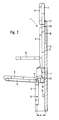
- Fig. 2 shows the seat 1 of FIG. 1, again partly in section, in a first position of use with the aforementioned elements 1 to 14.
- the seat group 6, 7 consisting of the shell 5 with the seat cushion 6 is about the axis of rotation 11 in the shown use position folded, with a seat shell-side stop 15 abuts the frame-side stop 12, so that the shell 5 can absorb a load.
- the shell 5 is folded out into this first or upper position of use against a spring of a known type, not shown. When the load is released, the shell 5 returns to the rest position due to the spring.
- the picture also shows an armrest 14 in the position of use.
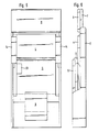
- the figures 5 and 6 show the aforementioned seat 1 in a view and in a side view.
- the pictures show in detail the frame 2 with the shells 5 and 7 and the upholstery 4, 6 and 8. Furthermore, the supporting link 9 and the armrests 14 are shown.
- a pushbutton 23 is arranged on the left on the underside of the shell 5. This is operatively connected to the rope 22 so that the lock 4a can be released by pressing this button.
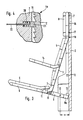
- FIG. 7 shows another embodiment of the invention in the form of a seat 7a with a frame 24, a support arm 25 and a seat shell 26 with a seat cushion 27.
- the support arm 25 can be pivoted about an axis 28 relative to the frame 24.
- the Shell 26 is pivotable about an axis 29 with respect to the supporting link 25.
- a back shell 30 with a back cushion 31 and a head cushion 32 is provided.
- a guide 34 is provided on each side of the shell 30, in which a sliding block 33 fixed to the frame engages.
- the frame 24 also has two stops 35 and 36.
- This seat 7a can also be brought into different positions of use by pivoting the supporting link 25. In this position, the sliding block 33 is located at the lower end of the guide 34.
Abstract
Description
Die Erfindung bezieht sich auf einen Sitz nach dem Oberbegriff des Anspruchs 1.The invention relates to a seat according to the preamble of claim 1.
Ein derartiger Sitz ist der US-PS 4,460,215 zu entnehmen. Diese zeigt eine klappbare Sitzanordnung mit Montagebeschlägen zur Montage an einer Wand mit einem Sitzschalenrahmen, mit einem vorderen und einem hinteren Bereich und einem Rückenlehnenrahmen, mit einem oberen und einem unteren Bereich, wobei der Sitzschalenrahmen an seinem hinteren Bereich an den besagten Beschlägen durch eine erste Anlenkung verbunden ist, so daß der Sitzschalenrahmen zwischen einer im allgemeinen horizontalen Gebrauchslage und einer im allgemeinen vertikalen Ruhelage schwenkbar ist, wobei der Rückenlehnenrahmen in einer zweiten Anlenkung in seinem oberen Bereich mit entsprechenden wandfesten Beschlägen verbunden ist, so daß der untere Bereich des Rückenlehnenrahmens zwischen einer Gebrauchslage und einer Ruhelage schwenkbar ist, wobei eine Führung mit einem Langloch zur Betätigung des Rückenlehnenrahmens vorgesehen ist, die mit ihrem einen Ende mit dem Beschlag am unteren Bereich des Rückenlehnenrahmens gelenkig verbunden ist, so daß die Führung zwischen einer im allgemeinen vertikal ausgeschwenkten Position und einer im allgemeinen horizontalen Anschlagposition schwenkbar ist, wodurch der untere Bereich des Rückenlehnenrahmens in seine Gebrauchslage gebracht wird, wobei eine Kurbel mit einem Hubzapfen fest mit dem Sitzschalenrahmen verbunden und mit diesem schwenkbar ist, wobei die Kurbel und die Führung mit dem Sitzschalenrahmen und dem Rückenlehnenrahmen derart zusammen wirken, daß nach rückwärts gerichtete Lasten, die am unteren Bereich des Rückenlehnenrahmens angreifen, als Druckkräfte über die Führung in den Beschlag eingeleitet werden, ohne daß Drehkräfte auf die Führung wirken.Such a seat can be found in US Pat. No. 4,460,215. This shows a foldable seat assembly with mounting hardware for mounting on a wall with a seat frame, with a front and a rear area and a backrest frame, with an upper and a lower area, the seat frame at its rear area on said fittings by a first linkage is connected so that the seat shell frame can be pivoted between a generally horizontal position of use and a generally vertical position of rest, the backrest frame being connected in a second articulation in its upper region to corresponding wall-mounted fittings, so that the lower region of the backrest frame is between a position of use and a rest position is pivotable, a guide having an elongated hole for actuating the backrest frame being provided, which is articulated at one end to the fitting at the lower region of the backrest frame, so that the guide between hen a generally vertically pivoted position and a generally horizontal stop position is pivotable, whereby the lower region of the backrest frame is brought into its position of use, wherein a crank with a crank pin is fixedly connected to and pivotable with the seat pan frame, the crank and the Guide together with the seat shell frame and the backrest frame in this way act that backward loads, which attack the lower region of the backrest frame, are introduced as pressure forces via the guide into the fitting without any torsional forces acting on the guide.
Wenn dieser Sitz in die Gebrauchslage gebracht wird, wird der untere Bereich der Rückenlehne um einen in deren oberem Bereich gelegenen Drehpunkt nach vorn geschwenkt. Diese Schwenkbarkeit der Rückenlehne dient nicht zur Verwirklichung einer bequemen Sitzposition, sondern zur Schaffung eines Stauraumes für den Sitzteil, wenn dieser in die Ruhelage gebracht wird. Dieser Sitz ist bei Flügen von längerer Dauer relativ unbequem, da er in der Gebrauchslage eine feste Geometrie aufweist. Hierdurch ist es nicht möglich, unterschiedliche Sitzpositionen herzustellen.When this seat is brought into the position of use, the lower region of the backrest is pivoted forward about a pivot point located in its upper region. This pivoting of the backrest does not serve to achieve a comfortable sitting position, but rather to create a storage space for the seat part when it is brought into the rest position. This seat is relatively uncomfortable on long flights because it has a solid geometry in the position of use. This makes it impossible to produce different seating positions.
Demgemäß liegt der Erfindung die Aufgabe zugrunde, einen gattungsgemäßen Sitz derart auszubilden, daß dieser auch bei längeren Flügen einen gegenüber bisherigen Sitzen höheren Sitzkomfort dadurch bietet, daß der Sitz in Gebrauchsstellung eine variable Geometrie aufweist.Accordingly, the invention has for its object to provide a generic seat in such a way that it offers greater seating comfort compared to previous seats even on longer flights in that the seat has a variable geometry in the position of use.
Diese Aufgabe wird bei einem gattungsgemäßen Sitz durch die kennzeichnenden Merkmale des Patentanspruchs 1 gelöst.This object is achieved in a generic seat by the characterizing features of claim 1.
Dabei ist insbesondere von Vorteil, daß der Sitz in unterschiedliche Gebrauchslagen gebracht werden kann, wobei sowohl die Rückenlehne als auch die Sitzschale bezüglich ihrer Winkellagen einstellbar sind.It is particularly advantageous that the seat can be brought into different positions of use, with both the backrest and the seat shell being adjustable in terms of their angular positions.
Weitere vorteilhafte Ausgestaltungen der Erfindung sind in den Unteransprüchen angegeben.Further advantageous embodiments of the invention are specified in the subclaims.
Die Erfindung ist anhand der Zeichnung dargestellt und in der Beispielbeschreibung näher erläutert. Es zeigen
- Fig. 1 eine Seitenansicht eines Flugbegleitersitzes,
- Fig. 2 den Sitz nach Fig. 1 in einer ersten Gebrauchslage,
- Fig. 3 den Sitz nach Fig 1 in einer zweiten Gebrauchslage,
- Fig. 4 eine Verriegelung,
- Fig. 5 eine Frontansicht eines Sitzes nach Fig. 1,
- Fig. 6 die Seitenansicht des Sitzes nach Fig. 5,
- Fig. 7 einen Sitz mit schwenkbarer Kopfstütze und
- Fig. 8 den Sitz nach Fig. 7 in einer Gebrauchslage.
- 1 is a side view of a flight attendant seat,
- 2 the seat of FIG. 1 in a first position of use,
- 3 shows the seat according to FIG. 1 in a second position of use,
- 4 shows a lock,
- 5 is a front view of a seat according to FIG. 1,
- 6 is a side view of the seat of FIG. 5,
- Fig. 7 is a seat with a pivotable headrest and
- Fig. 8 the seat of FIG. 7 in a position of use.
Fig 1 zeigt eine teilweise im Schnitt erscheinende Seitenansicht eines Sitzes 1, im wesentlichen bestehend aus einem Gestell 2, einer Schale 3 für das Rückenpolster 4, einer Schale 5 für ein Sitzpolster 6 und einer Schale 7 für ein Kopfpolster 8. Dabei ist ein Traglenker 9 um eine gestellfeste Drehachse 10 schwenkbar angeordnet, der seinerseits eine Drehachse 11 aufweist, in der die Schale 5 angelenkt ist. Im unteren Bereich des Gestells 2 sind ein erster Anschlag 12 und ein zweiter Anschlag 13 angeordnet. Zu beiden Seiten des Rückenpolsters 4 ist je eine hier nicht sichtbare ausschwenkbare Armlehne 14 angeordnet. Dieser Sitz kann an einer Kabinenwand und/oder am Fußboden der Kabine befestigt werden.1 shows a side view, partially in section, of a seat 1, essentially consisting of a
Fig. 2 zeigt den Sitz 1 nach Fig. 1, wieder teilweise geschnitten, in einer ersten Gebrauchslage mit den vorgenannten Elementen 1 bis 14. Dabei ist die aus der Schale 5 mit dem Sitzpolster 6 bestehende Sitzgruppe 6,7 um die Drehachse 11 in die gezeigte Gebrauchslage geklappt, wobei ein sitzschalenseitiger Anschlag 15 am gestellseitigen Anschlag 12 anliegt, so daß die Schale 5 damit eine Last aufnehmen kann. Das Herausklappen der Schale 5 in diese erste oder obere Gebrauchslage geschieht entgegen einer nicht gezeigten Feder bekannter Art. Bei Entlastung kehrt die Schale 5 aufgrund der Feder wieder in die Ruhelage zurück. Das Bild zeigt weiterhin eine in Gebrauchslage befindliche Armlehne 14. Diese ist auf an sich bekannte Weise schwenkbar ausgebildet, wobei durch einen hier nicht gezeigten Anschlag sichergestellt ist, daß die Lehne 14 eine im wesentlichen nach unten gerichtete Last aufnehmen kann. Das Gestell 2 weist in seinem oberen Bereich eine geradlinige Führung 16 für zwei Gleitelemente 17 und 18 auf, die ihrerseits fest mit der aus der Schale 7 und dem Kopfpolster 8 bestehenden Kopfstütze 7,8 verbunden sind. Damit ist die Kopfstütze 7,8 vertikal geführt. Die Schale 3 für das Rückenpolster 4 ist an ihrem oberen Ende mit dem Gleitelement 18 gelenkig verbunden. Die Drehachse 11, am unteren Ende der Schale 3, weist gegenüber der durch die Mittelpunkte der Gleitelemente 17 und 18 gezogenen Vertikalen einen Abstand e auf. Dies ergibt sich aus der in diesem Bereich gestrichelt gezeigten abgewinkelten Form der Schale 3.Fig. 2 shows the seat 1 of FIG. 1, again partly in section, in a first position of use with the aforementioned elements 1 to 14. The
Fig. 3 zeigt den Sitz 1 nach Fig.2 in einer anderen Gebrauchslage. Diese Lage zeichnet sich aus durch eine Schräglage der aus der Schale 3 mit dem Rückenpolster 4 bestehenden Rückenlehne 3,4 und ergibt sich durch Schwenkung des Traglenkers 9 entgegen dem Uhrzeigersinn um die gestellfeste Drehachse 10, bis die über die Drehachse 10 hinausragende Fortsetzung 9a des Traglenkers 9 am Anschlag 13 anliegt. Dise Bewegung erfolgt entgegen einer Feder, die dem Traglenker 9 ein rechtsdrehendes Moment erteilt. Dabei folgt der untere Bereich der Schale 3 der bogenförmigen Bewegung der Drehachse 11, wohingegen der obere Bereich dieser Schale 3 mit der Kopfstütze 7,8 infolge der vorbeschriebenen Führung 16 geradlinig nach unten wandert. Diese Bewegung kann nur ausgeführt werden, wenn vorher eine hier nicht gezeigte Verriegelung gelöst wird. Nachdem sich der Anschlag 15 vom Anschlag 12 zu Beginn der Drehung entfernt hat und während der Drehung bleibt die Winkellage der Sitzgruppe 5,6 gegenüber der Rückenlehne 3,4 annähernd konstant. Dies wird dadurch erreicht, daß sich der Anschlag 15 nunmehr gegen den abgewinkelten Teil der Schale 3 abstützt. Bei Entlastung kehrt die Schale 5, wie vorbeschrieben, wieder in ihre Ruhelage zurück, wobei gleichzeitig, unter der Wirkung des auf den Traglenker 9 wirkenden Momentes, die Schale 7 wieder in ihre obere Position gelangt. Damit ist wieder die obere Gebrauchslage des Sitzes erreicht. Die untere Gebrauchslage, die im wesentlichen gegeben ist durch die Schräglage der Rückenlehne 3,4 und eine gegenüber dem Fußboden jetzt tiefer liegende Sitzgruppe 5,6, zeichnet sich aus durch eine erhöhte Bequemlichkeit. Diese ergibt sich daraus, daß die Rückenachse und die Achse der Unterschenkel einer den Sitz benutzenden Person etwa parallel verlaufen. Um die Bequemlichkeit des Sitzes weiter zu erhöhen, ist vorgesehen, daß praktisch jede Gebrauchslage eingestellt werden kann, die innerhalb des durch die obere und die untere Gebrauchslage bzw. durch die Endlagen des Traglenkers 9 begrenzten Bereiches möglich ist. In kinematischer Hinsicht bilden der Traglenker 9, die Rückenschale 3 und das Gelenk 18 gleichsam einen exzentrischen Kurbeltrieb mit der Exzentrizität e. Dabei fungieren die Schale 3 als Schubstange und das Gelenk 18 mit der Führung 16 als Kreuzkopf.Fig. 3 shows the seat 1 of Figure 2 in a different position of use. This position is characterized by an inclined position of the
Fig. 4 zeigt die bereits erwähnte Verriegelung zum Fixieren der Schale 7 gegenüber dem Gestell 2. Seitens des Gestells ist eine Verzahnung 19 vorgesehen, in die ein mit einer Feder 20 belasteter Sperrschieber 21 eingreift. Die Verzahnung 19 und der Sperrschieber 21 bilden ein Richtungsgesperre, das eine Bewegung der Schale 7 nur nach oben ermöglicht. Nach unten wird die Schale 7 gegenüber dem Gestell 2 verriegelt. Mittels einer über ein Seil 22 eingeleiteten Bedienungsmaßnahme kann der Sperrschieber 21 entgegen der Kraft der Feder 20 aus der Verzahnung 19 ausgerückt werden, so daß jede unterhalb der oberen Gebrauchslage befindliche Position einstellbar ist. Bei Entlastung kehrt die Schale 3 trotz der Verriegelung wieder in ihre obere Gebrauchslage zurück.Fig. 4 shows the already mentioned locking for fixing the shell 7 with respect to the
Die Fign. 5 und 6 zeigen den vorgenannten Sitz 1 in der Ansicht bzw. in der Seitenansicht. Die Bilder zeigen im einzelnen das Gestell 2 mit den Schalen 5 und 7 und den Polstern 4, 6 und 8. Weiterhin sind der Traglenker 9 und die Armlehnen 14 gezeigt. Links an der Unterseite der Schale 5 ist eine Drucktaste 23 angeordnet. Diese steht mit dem Seil 22 Wirkverbindung, so daß die Verriegelung 4a durch Druck auf diese Taste lösbar ist.The figures 5 and 6 show the aforementioned seat 1 in a view and in a side view. The pictures show in detail the
Fig. 7 zeigt eine andere Ausgestaltung der Erfindung in Form eines Sitzes 7a mit einem Gestell 24, einem Traglenker 25 und einer Sitzschale 26 mit einem Sitzpolster 27. Der Traglenker 25 ist um eine Achse 28 gegenüber dem Gestell 24 schwenkbar. Die Schale 26 ist um eine Achse 29 gegenüber dem Traglenker 25 schwenkbar. Weiterhin ist eine Rückenschale 30 mit einem Rückenpolster 31 und einem Kopfpolster 32 vorgesehen. Seitlich der Schale 30 ist je eine Führung 34 vorgesehen, in die je ein gestellfester Gleitstein 33 eingreift. Das Gestell 24 weist weiterhin zwei Anschläge 35 und 36 auf. Auch dieser Sitz 7a kann durch Schwenken des Traglenkers 25 in unterschiedliche Gebrauchslagen gebracht werden. In dieser Lage befindet sich der Gleitstein 33 am unteren Ende der Führung 34.7 shows another embodiment of the invention in the form of a
Fig. 8 zeigt den Sitz nach Fig. 7 mit den Elementen 25 bis 35 in der unteren Gebrauchslage, die sich dadurch ergibt, daß der Traglenker 25 am Anschlag 35 anliegt. In dieser Position befindet sich der Gleitstein 33 am oberen Ende der Führung 34. Hierdurch nimmt die Rückenschale 30 die gezeigte Schräglage ein, wobei das Kopfpolster 32 in vorteilhafter Weise mit dem Rückenpolster 31 annähernd in einer Ebene liegt. Zur Fixierung der Rückenschale 30 gegenüber dem Gestell 24 ist auch hier eine lösbare Verriegelung vorgesehen, die hier jedoch nicht gezeigt ist. Auch im Falle dieser Ausgestaltung bilden der Traglenker 25 und die Schale 30, kinematisch gesehen, wieder einen Kurbeltrieb, diesmal im Form einer Kurbelschleife, wobei der Traglenker 25 die Funktion der Kurbel und die Schale 30 die Funktion der Schubstange übernimmt. Wegen der nach hinten ausschwenkenden Kopfstütze ist dieser Sitz besonders zur Befestigung am Fußboden geeignet. Eine Montage an einer Kabinenwand ist auch möglich, wenn entsprechende konstruktive Vorkehrungen getroffen werden.Fig. 8 shows the seat of FIG. 7 with the
Die Erfindung ist nicht auf die dargestellten und beschriebenen Beispielausführungen beschränkt. Sie erstreckt sich vielmehr auf alle Ausgestaltungen, die im Rahmen der Ansprüche denkbar sind.The invention is not restricted to the exemplary embodiments shown and described. Rather, it extends to all configurations that are conceivable within the scope of the claims.
Claims (4)
Priority Applications (1)
| Application Number | Priority Date | Filing Date | Title |
|---|---|---|---|
| AT89109896T ATE83993T1 (en) | 1988-07-04 | 1989-06-01 | SEAT, PARTICULARLY FOR A FLIGHT ATTENDANT. |
Applications Claiming Priority (2)
| Application Number | Priority Date | Filing Date | Title |
|---|---|---|---|
| DE3822574 | 1988-07-04 | ||
| DE3822574A DE3822574A1 (en) | 1988-07-04 | 1988-07-04 | SEAT, ESPECIALLY FOR A FLIGHT ATTENDANT |
Publications (3)
| Publication Number | Publication Date |
|---|---|
| EP0349762A2 true EP0349762A2 (en) | 1990-01-10 |
| EP0349762A3 EP0349762A3 (en) | 1990-06-27 |
| EP0349762B1 EP0349762B1 (en) | 1992-12-30 |
Family
ID=6357911
Family Applications (1)
| Application Number | Title | Priority Date | Filing Date |
|---|---|---|---|
| EP89109896A Expired - Lifetime EP0349762B1 (en) | 1988-07-04 | 1989-06-01 | Seat, in particular for a crewmember of an aircraft |
Country Status (4)
| Country | Link |
|---|---|
| US (1) | US4902069A (en) |
| EP (1) | EP0349762B1 (en) |
| AT (1) | ATE83993T1 (en) |
| DE (1) | DE3822574A1 (en) |
Cited By (19)
| Publication number | Priority date | Publication date | Assignee | Title |
|---|---|---|---|---|
| GB2264794A (en) * | 1992-03-06 | 1993-09-08 | Intel Corp | Low power consumption chip controller |
| US5586332A (en) * | 1993-03-24 | 1996-12-17 | Intel Corporation | Power management for low power processors through the use of auto clock-throttling |
| US5630146A (en) * | 1991-10-17 | 1997-05-13 | Intel Corporation | Method and apparatus for invalidating a cache while in a low power state |
| US5634131A (en) * | 1992-11-06 | 1997-05-27 | Intel Corporation | Method and apparatus for independently stopping and restarting functional units |
| US5821784A (en) * | 1995-12-29 | 1998-10-13 | Intel Corporation | Method and apparatus for generating 2/N mode bus clock signals |
| US5826067A (en) * | 1996-09-06 | 1998-10-20 | Intel Corporation | Method and apparatus for preventing logic glitches in a 2/n clocking scheme |
| US5834956A (en) * | 1995-12-29 | 1998-11-10 | Intel Corporation | Core clock correction in a 2/N mode clocking scheme |
| FR2962714A1 (en) * | 2010-07-19 | 2012-01-20 | Airbus Operations Sas | Folding seat for use by flight crew in cockpit of aircraft, has base and backrest, where folding seat is in configuration in which each of base and backrest extend vertically one above other in parallel manner |
| EP2574551A2 (en) | 2011-09-30 | 2013-04-03 | Airbus Operations | Cockpit of an aircraft comprising a folding seat |
| US9045230B2 (en) | 2012-02-14 | 2015-06-02 | C&D Zodiac, Inc. | Lavatory Monument Assembly |
| US9260189B2 (en) | 2012-02-14 | 2016-02-16 | C&D Zodiac, Inc. | Modular lavatory with alcove |
| WO2016030843A1 (en) * | 2014-08-26 | 2016-03-03 | Zodiac Seats France | Elastic fabric compact seat |
| WO2016091907A1 (en) * | 2014-12-09 | 2016-06-16 | Airbus Operations Gmbh | Flight attendant seat, arrangement having a flight attendant seat, and aircraft area |
| EP3072815A1 (en) * | 2015-03-27 | 2016-09-28 | AMI Industries, Inc. | Stowable reclining seat with lateral translation linkage |
| US9896212B2 (en) | 2012-02-14 | 2018-02-20 | C&D Zodiac, Inc. | Integrated centerline lavatory galley monument |
| FR3064599A1 (en) * | 2017-03-29 | 2018-10-05 | Airbus | RECOVERABLE ARMCHAIR FOR AIRCRAFT CAB |
| CN110155341A (en) * | 2019-06-06 | 2019-08-23 | 北京安达维尔航空设备有限公司 | A kind of observer's seat and its application method |
| CN110254727A (en) * | 2019-06-06 | 2019-09-20 | 北京安达维尔航空设备有限公司 | A kind of observer's seat and its application method of lateral folding and unfolding |
| GB2580292A (en) * | 2018-10-30 | 2020-07-22 | Zodiac Seats Uk Ltd | Aircraft seat and cabin arrangement |
Families Citing this family (52)
| Publication number | Priority date | Publication date | Assignee | Title |
|---|---|---|---|---|
| JPH0289947U (en) * | 1988-12-28 | 1990-07-17 | ||
| US5100199A (en) * | 1990-06-07 | 1992-03-31 | Vander Stel Louis M | Built-in infant seat |
| US5026118A (en) * | 1990-06-07 | 1991-06-25 | Vander Stel Louis M | Built-in infant's seat for vehicles |
| DE4125958C1 (en) * | 1991-08-06 | 1992-10-01 | Deutsche Airbus Gmbh, 2000 Hamburg, De | |
| GB2268876B (en) * | 1992-07-20 | 1997-03-12 | Flight Equip & Eng | Aircraft passenger seating |
| GB2270466B (en) * | 1992-09-09 | 1996-04-24 | Autoliv Dev | Improvements in or relating to a child seat |
| US5588700A (en) * | 1994-02-28 | 1996-12-31 | Douglas & Lomason Company | Child safety seat with side bolsters |
| US5564780A (en) * | 1994-09-26 | 1996-10-15 | Douglas & Lomason Company | Child restraint seat |
| AUPO678897A0 (en) * | 1997-05-14 | 1997-06-05 | Jpm Industries Pty Ltd | Foldable chair |
| US5918937A (en) * | 1997-06-23 | 1999-07-06 | Freedman Seating Co. | Folding seat |
| US6149528A (en) * | 1999-03-16 | 2000-11-21 | Universal City Studio, Inc. | Amusement ride vehicle folding seat |
| GB2372438C (en) * | 2001-02-23 | 2009-06-15 | Johnson Controls Tech Co | Improvements in or relating to vehicle seating |
| US7040703B2 (en) * | 2002-03-29 | 2006-05-09 | Garrex Llc | Health chair a dynamically balanced task chair |
| US7625046B2 (en) * | 2002-03-29 | 2009-12-01 | Garrex Llc | Task chair |
| DE10307870A1 (en) * | 2003-02-25 | 2004-09-09 | Airbus Deutschland Gmbh | Seat row arrangement in a passenger cabin of a commercial aircraft |
| WO2005006917A2 (en) * | 2003-07-09 | 2005-01-27 | Sanchez Gary L | Task chair |
| DE102004025980B4 (en) * | 2004-05-27 | 2010-04-29 | Airbus Deutschland Gmbh | Seat backrest for a crew compartment of an aircraft |
| US7490906B2 (en) | 2004-05-27 | 2009-02-17 | Airbus Deutschland Gmbh | Seat backrest for the crew rest compartment of an aircraft |
| EP1698552B1 (en) | 2005-03-03 | 2010-07-07 | Airbus Operations GmbH | Arrangement of first and second parts |
| DE102005009750B4 (en) * | 2005-03-03 | 2009-04-23 | Airbus Deutschland Gmbh | Assembly comprising a seat and a flight attendant seat |
| FR2883459B1 (en) * | 2005-03-22 | 2007-06-08 | Delagrave Sa | FOLDABLE SEAT WITH SEAT AND MOBILE BACKREST |
| US7559594B2 (en) * | 2006-03-03 | 2009-07-14 | Schukra Of North America, Ltd. | Fold flat seating |
| DE102009050903B4 (en) * | 2009-10-27 | 2014-02-13 | Siemens Aktiengesellschaft | vehicle seat |
| WO2012050587A1 (en) * | 2010-10-15 | 2012-04-19 | Bombardier Inc. | Aircraft interior configuration |
| DE102012005980A1 (en) * | 2012-03-23 | 2013-09-26 | Airbus Operations Gmbh | Adapter for securing a seat in a cabin of a vehicle, seat for a cabin of a vehicle, vehicle with a cabin and a seat |
| DE202012003007U1 (en) * | 2012-03-26 | 2013-06-27 | Zim Flugsitz Gmbh | Passenger seating |
| DE102012108352A1 (en) * | 2012-09-07 | 2014-03-13 | Recaro Aircraft Seating Gmbh & Co. Kg | Seat energy absorption device |
| US20140084640A1 (en) * | 2012-09-24 | 2014-03-27 | Gary Donald Walker | Sturdy Fold Down Seat |
| EP2743183A1 (en) * | 2012-12-14 | 2014-06-18 | Airbus Operations GmbH | Convertible cabin attendant seat |
| DE102013008289A1 (en) * | 2013-05-15 | 2014-11-20 | Airbus Operations Gmbh | aircraft area |
| US9856024B2 (en) | 2013-06-18 | 2018-01-02 | B/E Aerospace, Inc. | Compact aircraft cabin attendant seat |
| DE102014102378A1 (en) * | 2014-02-24 | 2015-08-27 | Airbus Operations Gmbh | Module for an aircraft cabin with a seat attached to a door |
| US9688168B2 (en) * | 2014-06-25 | 2017-06-27 | S2 Yachts, Inc. | Integrated seat and backrest |
| US10470578B2 (en) * | 2014-07-14 | 2019-11-12 | Seth EHLINGER | Wall mounted collapsible chair |
| DE102015110369B3 (en) * | 2015-06-26 | 2016-11-24 | Peak Technology GmbH | Airplane seat with seat reclining function |
| US10940948B2 (en) * | 2015-11-10 | 2021-03-09 | Safran Seats | Aircraft seat for cabin crew |
| US10065711B2 (en) | 2016-02-05 | 2018-09-04 | S2 Yachts Inc. | Multiple position boat seat |
| US9873510B2 (en) * | 2016-03-29 | 2018-01-23 | Ami Industries, Inc. | Contoured stowable seat |
| US10293944B2 (en) * | 2016-12-07 | 2019-05-21 | Rockwell Collins, Inc. | Components for enhancement of a low profile crew attendant seat |
| US10329021B2 (en) | 2016-12-16 | 2019-06-25 | Ami Industries, Inc. | Collapsible backrest |
| US20200108934A1 (en) * | 2017-04-04 | 2020-04-09 | Haeco Americas, Inc. | Seating assembly with staggered arrangement |
| US10464679B2 (en) | 2017-08-22 | 2019-11-05 | Ami Industries, Inc. | Stowable seat with pivoting seat pan for advanced comfort |
| JP7009151B2 (en) * | 2017-10-06 | 2022-01-25 | トヨタ紡織株式会社 | Vehicle seats and partitions |
| US10336221B2 (en) | 2017-10-18 | 2019-07-02 | Ami Industries, Inc. | Stowable seat with backrest release |
| US11291307B2 (en) * | 2018-04-20 | 2022-04-05 | Ergotech Solutions, Inc. | Body support |
| JP7103166B2 (en) * | 2018-11-02 | 2022-07-20 | トヨタ自動車株式会社 | Vehicle seat |
| JP7103168B2 (en) * | 2018-11-05 | 2022-07-20 | トヨタ自動車株式会社 | Vehicle seat structure |
| US10807720B2 (en) * | 2019-02-25 | 2020-10-20 | Goodrich Corporation | Detachable cabin attendant seat |
| US11472559B1 (en) * | 2019-03-29 | 2022-10-18 | B/E Aerospace, Inc. | Coil hinge for aircraft seat |
| DE102019123681A1 (en) * | 2019-09-04 | 2021-03-04 | Brose Fahrzeugteile SE & Co. Kommanditgesellschaft, Coburg | Morphing bench |
| CN113002781B (en) * | 2021-03-18 | 2023-05-23 | 中国商用飞机有限责任公司 | Crewmember seat |
| US11820265B2 (en) * | 2022-02-03 | 2023-11-21 | Brose Fahrzeugteile SE & Co. Kommanditgesellschaft, Coburg | Vehicle seat |
Citations (3)
| Publication number | Priority date | Publication date | Assignee | Title |
|---|---|---|---|---|
| US4460215A (en) * | 1981-09-30 | 1984-07-17 | The Boeing Company | Folding seat assembly |
| DE8708102U1 (en) * | 1987-06-06 | 1987-08-20 | Keiper Recaro Gmbh & Co, 5630 Remscheid, De | |
| EP0268749A1 (en) * | 1986-10-13 | 1988-06-01 | Deutsche Airbus GmbH | Vehicle seat |
Family Cites Families (5)
| Publication number | Priority date | Publication date | Assignee | Title |
|---|---|---|---|---|
| FR570199A (en) * | 1922-11-14 | 1924-04-24 | Device applicable to armchairs for automatic transformation into a lounge chair | |
| US1761673A (en) * | 1928-04-11 | 1930-06-03 | Clearwater Lumber Company Inc | Folding seat |
| US1784390A (en) * | 1929-07-16 | 1930-12-09 | Howard E Rice | Foldable chair |
| US3093414A (en) * | 1960-01-14 | 1963-06-11 | Miller Herman Inc | Folding chair |
| US3594037A (en) * | 1970-04-09 | 1971-07-20 | Mc Donnell Douglas Corp | Cabin attendant seat |
-
1988
- 1988-07-04 DE DE3822574A patent/DE3822574A1/en active Granted
-
1989
- 1989-06-01 AT AT89109896T patent/ATE83993T1/en not_active IP Right Cessation
- 1989-06-01 EP EP89109896A patent/EP0349762B1/en not_active Expired - Lifetime
- 1989-07-03 US US07/375,391 patent/US4902069A/en not_active Expired - Fee Related
Patent Citations (3)
| Publication number | Priority date | Publication date | Assignee | Title |
|---|---|---|---|---|
| US4460215A (en) * | 1981-09-30 | 1984-07-17 | The Boeing Company | Folding seat assembly |
| EP0268749A1 (en) * | 1986-10-13 | 1988-06-01 | Deutsche Airbus GmbH | Vehicle seat |
| DE8708102U1 (en) * | 1987-06-06 | 1987-08-20 | Keiper Recaro Gmbh & Co, 5630 Remscheid, De |
Cited By (36)
| Publication number | Priority date | Publication date | Assignee | Title |
|---|---|---|---|---|
| US5634117A (en) * | 1991-10-17 | 1997-05-27 | Intel Corporation | Apparatus for operating a microprocessor core and bus controller at a speed greater than the speed of a bus clock speed |
| US5630146A (en) * | 1991-10-17 | 1997-05-13 | Intel Corporation | Method and apparatus for invalidating a cache while in a low power state |
| US5388265A (en) * | 1992-03-06 | 1995-02-07 | Intel Corporation | Method and apparatus for placing an integrated circuit chip in a reduced power consumption state |
| GB2264794B (en) * | 1992-03-06 | 1995-09-20 | Intel Corp | Method and apparatus for automatic power management in a high integration floppy disk controller |
| GB2264794A (en) * | 1992-03-06 | 1993-09-08 | Intel Corp | Low power consumption chip controller |
| US5634131A (en) * | 1992-11-06 | 1997-05-27 | Intel Corporation | Method and apparatus for independently stopping and restarting functional units |
| US5586332A (en) * | 1993-03-24 | 1996-12-17 | Intel Corporation | Power management for low power processors through the use of auto clock-throttling |
| US5821784A (en) * | 1995-12-29 | 1998-10-13 | Intel Corporation | Method and apparatus for generating 2/N mode bus clock signals |
| US5834956A (en) * | 1995-12-29 | 1998-11-10 | Intel Corporation | Core clock correction in a 2/N mode clocking scheme |
| US6104219A (en) * | 1995-12-29 | 2000-08-15 | Intel Corporation | Method and apparatus for generating 2/N mode bus clock signals |
| US6208180B1 (en) | 1995-12-29 | 2001-03-27 | Intel Corporation | Core clock correction in a 2/N mode clocking scheme |
| US5826067A (en) * | 1996-09-06 | 1998-10-20 | Intel Corporation | Method and apparatus for preventing logic glitches in a 2/n clocking scheme |
| FR2962714A1 (en) * | 2010-07-19 | 2012-01-20 | Airbus Operations Sas | Folding seat for use by flight crew in cockpit of aircraft, has base and backrest, where folding seat is in configuration in which each of base and backrest extend vertically one above other in parallel manner |
| EP2574551A2 (en) | 2011-09-30 | 2013-04-03 | Airbus Operations | Cockpit of an aircraft comprising a folding seat |
| US9340293B2 (en) | 2011-09-30 | 2016-05-17 | Airbus Operations (S.A.S.) | Aircraft flight deck comprising a folding seat |
| US10301025B2 (en) | 2012-02-14 | 2019-05-28 | C&D Zodiac, Inc. | Business class modular lavatory with alcove |
| US10093421B2 (en) | 2012-02-14 | 2018-10-09 | C&D Zodiac, Inc. | Dual modular lavatory with alcoves |
| US9260189B2 (en) | 2012-02-14 | 2016-02-16 | C&D Zodiac, Inc. | Modular lavatory with alcove |
| US10358219B2 (en) | 2012-02-14 | 2019-07-23 | C&D Zodiac, Inc. | Modular lavatory with sink alcove |
| US9045230B2 (en) | 2012-02-14 | 2015-06-02 | C&D Zodiac, Inc. | Lavatory Monument Assembly |
| US9527591B2 (en) | 2012-02-14 | 2016-12-27 | C&D Zodiac, Inc. | Modular lavatory with alcove |
| US9896212B2 (en) | 2012-02-14 | 2018-02-20 | C&D Zodiac, Inc. | Integrated centerline lavatory galley monument |
| US9981747B2 (en) | 2012-02-14 | 2018-05-29 | C&D Zodiac, Inc. | Lavatory with recessed flight attendant seat |
| US10023314B2 (en) | 2012-02-14 | 2018-07-17 | C&D Zodiac, Inc. | Quad modular lavatory with alcoves |
| WO2016030843A1 (en) * | 2014-08-26 | 2016-03-03 | Zodiac Seats France | Elastic fabric compact seat |
| US10040557B2 (en) | 2014-12-09 | 2018-08-07 | Airbus Operations Gmbh | Flight attendant seat, arrangement having a flight attendant seat, and aircraft area |
| WO2016091907A1 (en) * | 2014-12-09 | 2016-06-16 | Airbus Operations Gmbh | Flight attendant seat, arrangement having a flight attendant seat, and aircraft area |
| EP3072815A1 (en) * | 2015-03-27 | 2016-09-28 | AMI Industries, Inc. | Stowable reclining seat with lateral translation linkage |
| FR3064599A1 (en) * | 2017-03-29 | 2018-10-05 | Airbus | RECOVERABLE ARMCHAIR FOR AIRCRAFT CAB |
| US10913537B2 (en) | 2017-03-29 | 2021-02-09 | Airbus Interiors Services | Retractable chair for an aircraft cabin |
| GB2580292A (en) * | 2018-10-30 | 2020-07-22 | Zodiac Seats Uk Ltd | Aircraft seat and cabin arrangement |
| GB2580292B (en) * | 2018-10-30 | 2022-11-30 | Safran Seats Gb Ltd | Aircraft seat and cabin arrangement |
| US11518520B2 (en) | 2018-10-30 | 2022-12-06 | Safran Seats GB Limited | Aircraft seat and cabin arrangement |
| CN110155341A (en) * | 2019-06-06 | 2019-08-23 | 北京安达维尔航空设备有限公司 | A kind of observer's seat and its application method |
| CN110254727A (en) * | 2019-06-06 | 2019-09-20 | 北京安达维尔航空设备有限公司 | A kind of observer's seat and its application method of lateral folding and unfolding |
| CN110155341B (en) * | 2019-06-06 | 2020-07-28 | 北京安达维尔航空设备有限公司 | Observer seat and using method thereof |
Also Published As
| Publication number | Publication date |
|---|---|
| DE3822574C2 (en) | 1991-01-17 |
| US4902069A (en) | 1990-02-20 |
| DE3822574A1 (en) | 1990-01-11 |
| EP0349762A3 (en) | 1990-06-27 |
| ATE83993T1 (en) | 1993-01-15 |
| EP0349762B1 (en) | 1992-12-30 |
Similar Documents
| Publication | Publication Date | Title |
|---|---|---|
| EP0349762B1 (en) | Seat, in particular for a crewmember of an aircraft | |
| DE19930922B4 (en) | chair | |
| DE60119346T2 (en) | SEAT UNIT WITH SELF-ADJUSTING HEADREST | |
| DE3630503C2 (en) | ||
| EP2051606B1 (en) | Armchair | |
| EP1704092B1 (en) | Vehicle seat, particularly an air passenger seat | |
| DE10247131B4 (en) | vehicle seat | |
| AT392889B (en) | TURNOVABLE SEAT FURNITURE | |
| WO2001091614A1 (en) | Chair | |
| WO2006053657A1 (en) | Vehicle seat in particular motor vehicle seat | |
| DE19830418B4 (en) | chair arrangement | |
| DE19620872A1 (en) | Front car seat with adjustable length and height | |
| WO2006074764A2 (en) | Armchair | |
| EP3965617B1 (en) | Seating furniture having dual-motor wall-away function | |
| EP1769704A2 (en) | Seating/lying furniture | |
| DE3243747C2 (en) | ||
| DE10107197A1 (en) | Vehicle seat, in particular passenger seat | |
| DE19812137A1 (en) | Seat arrangement with at least two seats arranged side by side | |
| DE2601691C3 (en) | Lever adjustment gear for reclining chairs | |
| DE4219599C2 (en) | Synchronizing device for office chairs or the like | |
| DE1429413B2 (en) | FITTING FOR AN ARMCHAIR ADJUSTABLE IN MULTIPLE POSITIONS | |
| DE1159147B (en) | Lever control device for the leg rest of an adjustable chair | |
| DE19700617C5 (en) | armchair | |
| DE19947187A1 (en) | Seating furniture has fixed support surfaces for the arm rests when folded down to convert into a bed and a lever mechanism to lock the arm rest(s) in place | |
| DE3151954C2 (en) | Adjustable passenger seat for a motor vehicle, in particular an ambulance |
Legal Events
| Date | Code | Title | Description |
|---|---|---|---|
| PUAI | Public reference made under article 153(3) epc to a published international application that has entered the european phase |
Free format text: ORIGINAL CODE: 0009012 |
|
| AK | Designated contracting states |
Kind code of ref document: A2 Designated state(s): AT BE CH ES FR GB GR IT LI LU NL SE |
|
| PUAL | Search report despatched |
Free format text: ORIGINAL CODE: 0009013 |
|
| AK | Designated contracting states |
Kind code of ref document: A3 Designated state(s): AT BE CH ES FR GB GR IT LI LU NL SE |
|
| 17P | Request for examination filed |
Effective date: 19900619 |
|
| RAP1 | Party data changed (applicant data changed or rights of an application transferred) |
Owner name: DEUTSCHE AIRBUS GMBH |
|
| 17Q | First examination report despatched |
Effective date: 19910729 |
|
| GRAA | (expected) grant |
Free format text: ORIGINAL CODE: 0009210 |
|
| AK | Designated contracting states |
Kind code of ref document: B1 Designated state(s): AT BE CH ES FR GB GR IT LI LU NL SE |
|
| PG25 | Lapsed in a contracting state [announced via postgrant information from national office to epo] |
Ref country code: IT Free format text: LAPSE BECAUSE OF FAILURE TO SUBMIT A TRANSLATION OF THE DESCRIPTION OR TO PAY THE FEE WITHIN THE PRE;WARNING: LAPSES OF ITALIAN PATENTS WITH EFFECTIVE DATE BEFORE 2007 MAY HAVE OCCURRED AT ANY TIME BEFORE 2007. THE CORRECT EFFECTIVE DATE MAY BE DIFFERENT FROM THE ONE RECORDED.SCRIBED TIME-LIMIT Effective date: 19921230 Ref country code: ES Free format text: THE PATENT HAS BEEN ANNULLED BY A DECISION OF A NATIONAL AUTHORITY Effective date: 19921230 Ref country code: FR Effective date: 19921230 Ref country code: GB Effective date: 19921230 Ref country code: SE Effective date: 19921230 Ref country code: GR Free format text: LAPSE BECAUSE OF FAILURE TO SUBMIT A TRANSLATION OF THE DESCRIPTION OR TO PAY THE FEE WITHIN THE PRESCRIBED TIME-LIMIT Effective date: 19921230 Ref country code: BE Effective date: 19921230 Ref country code: NL Effective date: 19921230 |
|
| REF | Corresponds to: |
Ref document number: 83993 Country of ref document: AT Date of ref document: 19930115 Kind code of ref document: T |
|
| EN | Fr: translation not filed | ||
| PG25 | Lapsed in a contracting state [announced via postgrant information from national office to epo] |
Ref country code: AT Effective date: 19930601 |
|
| NLV1 | Nl: lapsed or annulled due to failure to fulfill the requirements of art. 29p and 29m of the patents act | ||
| PG25 | Lapsed in a contracting state [announced via postgrant information from national office to epo] |
Ref country code: LI Effective date: 19930630 Ref country code: CH Effective date: 19930630 Ref country code: LU Free format text: LAPSE BECAUSE OF NON-PAYMENT OF DUE FEES Effective date: 19930630 |
|
| GBV | Gb: ep patent (uk) treated as always having been void in accordance with gb section 77(7)/1977 [no translation filed] |
Effective date: 19921230 |
|
| PLBE | No opposition filed within time limit |
Free format text: ORIGINAL CODE: 0009261 |
|
| STAA | Information on the status of an ep patent application or granted ep patent |
Free format text: STATUS: NO OPPOSITION FILED WITHIN TIME LIMIT |
|
| 26N | No opposition filed | ||
| REG | Reference to a national code |
Ref country code: CH Ref legal event code: PL |
|
| REG | Reference to a national code |
Ref country code: FR Ref legal event code: D6 |