EP0349635B1 - Turbine combustor with tangential fuel injection and bender jets - Google Patents
Turbine combustor with tangential fuel injection and bender jets Download PDFInfo
- Publication number
- EP0349635B1 EP0349635B1 EP89901685A EP89901685A EP0349635B1 EP 0349635 B1 EP0349635 B1 EP 0349635B1 EP 89901685 A EP89901685 A EP 89901685A EP 89901685 A EP89901685 A EP 89901685A EP 0349635 B1 EP0349635 B1 EP 0349635B1
- Authority
- EP
- European Patent Office
- Prior art keywords
- fuel
- jets
- annulus
- wall
- primary combustion
- Prior art date
- Legal status (The legal status is an assumption and is not a legal conclusion. Google has not performed a legal analysis and makes no representation as to the accuracy of the status listed.)
- Expired - Lifetime
Links
Images
Classifications
-
- F—MECHANICAL ENGINEERING; LIGHTING; HEATING; WEAPONS; BLASTING
- F23—COMBUSTION APPARATUS; COMBUSTION PROCESSES
- F23R—GENERATING COMBUSTION PRODUCTS OF HIGH PRESSURE OR HIGH VELOCITY, e.g. GAS-TURBINE COMBUSTION CHAMBERS
- F23R3/00—Continuous combustion chambers using liquid or gaseous fuel
- F23R3/02—Continuous combustion chambers using liquid or gaseous fuel characterised by the air-flow or gas-flow configuration
- F23R3/04—Air inlet arrangements
-
- F—MECHANICAL ENGINEERING; LIGHTING; HEATING; WEAPONS; BLASTING
- F23—COMBUSTION APPARATUS; COMBUSTION PROCESSES
- F23R—GENERATING COMBUSTION PRODUCTS OF HIGH PRESSURE OR HIGH VELOCITY, e.g. GAS-TURBINE COMBUSTION CHAMBERS
- F23R3/00—Continuous combustion chambers using liquid or gaseous fuel
- F23R3/28—Continuous combustion chambers using liquid or gaseous fuel characterised by the fuel supply
-
- F—MECHANICAL ENGINEERING; LIGHTING; HEATING; WEAPONS; BLASTING
- F05—INDEXING SCHEMES RELATING TO ENGINES OR PUMPS IN VARIOUS SUBCLASSES OF CLASSES F01-F04
- F05B—INDEXING SCHEME RELATING TO WIND, SPRING, WEIGHT, INERTIA OR LIKE MOTORS, TO MACHINES OR ENGINES FOR LIQUIDS COVERED BY SUBCLASSES F03B, F03D AND F03G
- F05B2250/00—Geometry
- F05B2250/30—Arrangement of components
- F05B2250/32—Arrangement of components according to their shape
- F05B2250/322—Arrangement of components according to their shape tangential
Definitions
- This invention relates to gas turbines, and more particularly, to an improved combustor for use in gas turbines.
- French patent FR-A-1276596 illustrates a number of arrangements for the supply of fuel and combustion air to an annular combustor.
- the fuel is injected axially through the end wall of the combustion chamber, while primary combustion air and secondary cooling air are introduced through openings in the inner and outer walls.
- primary combustion air and secondary cooling air are introduced through openings in the inner and outer walls.
- the inlet openings generally impart a tangential component to the inlet air.
- British patent application GB-A-2009860 illustrates a method of supplying fuel to a cylindrical combustion chamber by creating a film of fuel over the surface of at least one of the primary air inlets arranged about the outer wall of the chamber. There is no disclosure of tangentially injecting air or fuel.
- the present invention is directed to overcoming one or more of the above problems.
- An exemplary embodiment of the invention achieves the foregoing objects in a gas turbine including a rotor having compressor blades and turbine blades.
- An inlet is located adjacent one side of the compressor blades and a diffuser is located adjacent the other side of the compressor blades.
- a nozzle is disposed adjacent the turbine blades for directing hot gasses at the turbine blades to cause rotation of the rotor and an annular combustor is disposed about the rotor and has an outlet connected to the nozzle and a primary combustion annulus remote from the outlet.
- a plurality of fuel injectors for injecting fuel to the primary combustion annulus are provided and are substantially equally angular spaced about the same. They are configured to inject fuel into the primary combustion annulus in a nominally tangential direction.
- Combustion supporting air jets are located about the primary combustion annulus in alternating relation with the fuel injectors.
- the jets are configured to introduce a combustion supporting air into the primary combustion annulus in a nominally tangential direction.
- combustion supporting air from the jets uniformly distributes burning fuel about the annulus to thereby enable the use of fewer fuel injectors while avoiding the presence of hot spots or cold spots.
- the fuel flow path in each injector may be increased in size to thereby reduce the possibility of clogging.
- the jets are in fluid communication with the diffuser to receive compressed air therefrom.
- the fuel injectors comprise fuel nozzles having ends within the primary combustion annulus and air atomizing nozzles for the combustion supporting air surround each of the ends of the fuel injector fuel nozzles.
- the invention contemplates the use of a compressed air housing surrounding the combustor in spaced relation thereto and in fluid communication with the diffuser.
- the jets open to the interface of the housing and combustor to receive compressed air therefrom.
- the combustor has an inner wall and and outer wall and the injectors are located on the outer wall and oriented to generally inject on a direction tangential to the inner wall.
- FIG. 1 An exemplary embodiment of a gas turbine made according to the invention is illustrated in the drawings in the form of a radial flow gas turbine.
- the invention is not so limited, having applicability to any form of turbine or other fuel combusting device requiring an annular combustor.
- the turbine includes a rotary shaft 10 journalled by bearings not shown. Adjacent one end of the shaft 10 is an inlet area 12.
- the shaft 10 mounts a rotor, generally designated 14 which may be of conventional construction. Accordingly, the same includes a plurality of compressor blades 16 adjacent the inlet 12.
- a compressor blade shroud 18 is provided in adjacency thereto and just radially outwardly of the radially outer extremities of the compressor blades 18 is a conventional diffuser 20.
- the rotor 14 has a plurality of turbine blades 22. Just radially outwardly of the turbine blades 22 is an annular nozzle 24 which is adapted to receive hot gasses of combustion from a combustor, generally designated 26.
- the compressor system including the blades 16, shroud 18 and diffuser 20 delivers hot air to the combustor 26, and via dilution air passages 27, to the nozzle 24 along with the gasses of combustion. That is to say, hot gasses of combustion from the combustor 26, are directed via the nozzle 24 against the blades 22 to cause rotation of the rotor 14 and thus the shaft 10.
- the latter may be, of course, coupled to some sort of apparatus requiring the performance of useful work.
- a turbine blade shroud 28 is interfitted with the combustor 26 to close off the flow path from the nozzle 24 and confine the expanding gas to the area of the turbine blades 22.
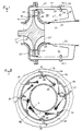
- the combustor 26 has a generally cylindrical inner wall 32 and a generally cylindrical outer wall 34. The two are concentric and merge to a necked down area 36 which serves as an outlet from the interior annulus 38 of the combustor to the nozzle 24.
- a third wall 39 generally concentric with the walls 32 and 34, interconnects the same to further define the annulus 38
- the interior annulus 38 of the combustor 26 includes a primary combustion zone 40.
- primary combustion zone it is meant that this is the area in which the burning of fuel primarily occurs. Other combustion may, in some instances, occur downstream from the primary combustion area 40 in the direction of the outlet 36.
- the primary combustion zone 40 is an annulus or annular space defined by the generally radially inner wall 32, the generally radially outer wall 34 and the wall 39.
- a further wall 44 is generally concentric to the walls 32 and 34 and is located radially outwardly of the latter.
- the wall 44 extends to the outlet of the diffuser 20 and thus serves to contain and direct compressed air from the compressor system to the combustor 26.
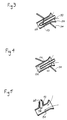
- the combustor 26 is provided with a plurality of conventional fuel injection nozzles 50, one of which is illustrated in Fig. 3.
- the fuel injection nozzles 50 have ends 52 disposed within the primary combustion zone 40 and which are configured to be nominally tangential to the inner wall 32.
- the fuel injection nozzles 50 conventionally utilize the pressure drop of fuel across swirl generating orifices 53 to accomplish fuel atomization.
- Tubes 54 surround the nozzles 50. High velocity air from the compressor flows through the tubes 54 to enhance fuel atomization. Thus the tubes 54 serve as air injection tubes.
- the fuel injecting nozzles 50 are equally angularly spaced about the primary combustion annulus 40 and disposed between each pair of adjacent nozzles 50 is a combustion supporting air jet 56.
- the jets 56 are located on the wall 34 and establish fluid communication between the air delivery annulus defined by the walls 34 and 44 and the primary combustion annulus 40.
- These jets 56 may be somewhat colloquially termed "bender" jets as will appear. They are also oriented so that the combustion supporting air entering through them enters the primary combustion annulus 40 in a direction nominally tangential to the inner wall 32.
- the injectors 50 and jets 56 are coplanar or in relatively closely spaced planes remote from the outlet area 36. Such plane or planes are transverse to the axis of the shaft 10.
- the same may be replaced with simple tubes 60 as seen in Fig. 4.
- the high velocity of the air flowing through the air injection tubes 54 provides the required fuel atomization as well as a desirable and necessary tangential mix of fuel and air.
- each air injection tube 54 might be provided with a port 62 in one side thereof for receipt of the nozzle 50 or a tube 60.
- This form of the invention is illustrated in Fig. 5.
- Fuel emanating from each of the nozzles 50 will enter along a line such as shown at "F" in connection with the lowermost nozzle 50 in Fig. 2. This line will of course be straight and it will be expected that the fuel will diverge from it somewhat. As the fuel approaches the adjacent bender jet 56 in the clockwise direction, the incoming air from the diffuser 20 and compressor blades 16 will tend to deflect or bend the fuel stream to a location more centrally of the primary combustion annulus 40 as indicated by the curved line "S".
- each bender jet 56 which may be of relatively inexpensive construction, has the ability to replace one, much more extensive fuel injector nozzle 50.
- the fuel flow passages of the remaining fuel injection nozzles can be increased in diameter slightly over 40%. This increase in diameter reduces the possibility of plugging of the fuel injectors nozzles 50 to provide a more trouble free apparatus.
Abstract
Description
- This invention relates to gas turbines, and more particularly, to an improved combustor for use in gas turbines.
- It has long been known that achieving uniform circumferential turbine inlet temperature distribution in gas turbines is highly desirable. Uniform distribution minimizes hot spots and cold spots to maximize efficiency of operation as well as prolongs the life of those parts of the turbine exposed to hot gases.
- French patent FR-A-1276596 illustrates a number of arrangements for the supply of fuel and combustion air to an annular combustor. Preferably, the fuel is injected axially through the end wall of the combustion chamber, while primary combustion air and secondary cooling air are introduced through openings in the inner and outer walls. However, it is possible to supply fuel through injectors placed in the air inlet openings. The inlet openings generally impart a tangential component to the inlet air.
- British patent application GB-A-2009860 illustrates a method of supplying fuel to a cylindrical combustion chamber by creating a film of fuel over the surface of at least one of the primary air inlets arranged about the outer wall of the chamber. There is no disclosure of tangentially injecting air or fuel.
- To achieve uniform turbine inlet temperature distribution in gas turbines having annular combustors, one has had to provide a large number of fuel injectors to assure that the fuel is uniformly distributed in the combustion air. Fuel injectors are quite expensive with the consequence that the use of a large number of them is not economically satisfactory. Moreover, as the number of fuel injectors increases in a system, with unchanged fuel consumption, the flow area for fuel in each injector becomes smaller. As the fuel flow passages become progressively smaller, the injectors are more prone to clogging due to very small contaminants in the fuel.
- This in turn creates the very problem sought to be done away with through the use of a number of fuel injectors. In particular, a fouled fuel injector will result in a non uniform turbine inlet temperature in an annular combustor with the result that hot and cold spots occur.
- To avoid this difficulty, the prior art ( for example FR-A-1276596, discussed above ) has suggested that by and large axial injection using a plurality of injectors be modified to the extent that such injectors inject the fuel into the annular combustion chamber with some sort of tangential component. The resulting swirl of fuel and combustion supporting gas provides a much more uniform mix of fuel with the air to provide a more uniform burn and thus achieve more circumferential uniformity in the turbine inlet temperature. However, this solution deals only with minimizing the presence of hot and/or cold spots when one or more injectors plug and does not deal with the desirability of eliminating a number of fuel injectors to reduce cost and/or avoiding the use of injectors having very small fuel flow passages which are prone to clogging.
- The present invention is directed to overcoming one or more of the above problems.
- It is the principal object of the invention to provide a new and improved annular combustor for a gas turbine. More specifically, it is an object of the invention to provide such a combustor wherein the number of fuel injectors may be minimized and yet uniform circumferential turbine inlet temperature distribution retained along with a minimization of the possibility of the fuel injectors plugging.
- An exemplary embodiment of the invention achieves the foregoing objects in a gas turbine including a rotor having compressor blades and turbine blades. An inlet is located adjacent one side of the compressor blades and a diffuser is located adjacent the other side of the compressor blades. A nozzle is disposed adjacent the turbine blades for directing hot gasses at the turbine blades to cause rotation of the rotor and an annular combustor is disposed about the rotor and has an outlet connected to the nozzle and a primary combustion annulus remote from the outlet. A plurality of fuel injectors for injecting fuel to the primary combustion annulus are provided and are substantially equally angular spaced about the same. They are configured to inject fuel into the primary combustion annulus in a nominally tangential direction. Combustion supporting air jets are located about the primary combustion annulus in alternating relation with the fuel injectors. The jets are configured to introduce a combustion supporting air into the primary combustion annulus in a nominally tangential direction. Thus, combustion supporting air from the jets uniformly distributes burning fuel about the annulus to thereby enable the use of fewer fuel injectors while avoiding the presence of hot spots or cold spots. Moreover, because the number of fuel injectors for a given turbine is minimized, the fuel flow path in each injector may be increased in size to thereby reduce the possibility of clogging.
- According to a preferred embodiment, the jets are in fluid communication with the diffuser to receive compressed air therefrom.
- In a highly preferred embodiment, the fuel injectors comprise fuel nozzles having ends within the primary combustion annulus and air atomizing nozzles for the combustion supporting air surround each of the ends of the fuel injector fuel nozzles.
- The invention contemplates the use of a compressed air housing surrounding the combustor in spaced relation thereto and in fluid communication with the diffuser. The jets open to the interface of the housing and combustor to receive compressed air therefrom.
- In a highly preferred embodiment, the combustor has an inner wall and and outer wall and the injectors are located on the outer wall and oriented to generally inject on a direction tangential to the inner wall.
- Other objects and advantages will become apparent from the following specification taken in connection with the accompanying drawings.
-
- Fig. 1 is a somewhat schematic, sectional view of a turbine made according to the invention;
- Fig. 2 is a sectional view taken approximately along the line 2-2 in Fig. 1;
- Fig. 3 is a fragmentary, sectional view of a conventional form of fuel injection nozzle that may be utilized in the invention;
- Fig. 4 is a view similar to Fig. 3 but of a modified form of fuel injection nozzle; and
- Fig. 5 is a view similar to Figs. 3 and 4 but of a further modified fuel injection nozzle.
- An exemplary embodiment of a gas turbine made according to the invention is illustrated in the drawings in the form of a radial flow gas turbine. However, the invention is not so limited, having applicability to any form of turbine or other fuel combusting device requiring an annular combustor.
- The turbine includes a
rotary shaft 10 journalled by bearings not shown. Adjacent one end of theshaft 10 is an inlet area 12. Theshaft 10 mounts a rotor, generally designated 14 which may be of conventional construction. Accordingly, the same includes a plurality ofcompressor blades 16 adjacent the inlet 12. A compressor blade shroud 18 is provided in adjacency thereto and just radially outwardly of the radially outer extremities of the compressor blades 18 is aconventional diffuser 20. - Oppositely of the
compressor blades 16, the rotor 14 has a plurality ofturbine blades 22. Just radially outwardly of theturbine blades 22 is anannular nozzle 24 which is adapted to receive hot gasses of combustion from a combustor, generally designated 26. The compressor system including theblades 16, shroud 18 anddiffuser 20 delivers hot air to thecombustor 26, and viadilution air passages 27, to thenozzle 24 along with the gasses of combustion. That is to say, hot gasses of combustion from thecombustor 26, are directed via thenozzle 24 against theblades 22 to cause rotation of the rotor 14 and thus theshaft 10. The latter may be, of course, coupled to some sort of apparatus requiring the performance of useful work. - A
turbine blade shroud 28 is interfitted with thecombustor 26 to close off the flow path from thenozzle 24 and confine the expanding gas to the area of theturbine blades 22. - The
combustor 26 has a generally cylindricalinner wall 32 and a generally cylindricalouter wall 34. The two are concentric and merge to a necked downarea 36 which serves as an outlet from the interior annulus 38 of the combustor to thenozzle 24. Athird wall 39, generally concentric with thewalls - Oppositely of the
outlet 36, and adjacent thewall 39, the interior annulus 38 of thecombustor 26 includes aprimary combustion zone 40. By primary combustion zone, it is meant that this is the area in which the burning of fuel primarily occurs. Other combustion may, in some instances, occur downstream from theprimary combustion area 40 in the direction of theoutlet 36. As mentioned earlier, provision is made for the injection of dilution air through thepassageways 27 into thecombustor 26 downstream of theprimary combustion zone 40 to cool the gasses of combustion to a temperature suitable for application to theturbine blades 22 via thenozzle 24. - In any event, it will be seen that the
primary combustion zone 40 is an annulus or annular space defined by the generally radiallyinner wall 32, the generally radiallyouter wall 34 and thewall 39. - A
further wall 44 is generally concentric to thewalls wall 44 extends to the outlet of thediffuser 20 and thus serves to contain and direct compressed air from the compressor system to thecombustor 26. - As best seen in Fig. 2, the
combustor 26 is provided with a plurality of conventionalfuel injection nozzles 50, one of which is illustrated in Fig. 3. Thefuel injection nozzles 50 have ends 52 disposed within theprimary combustion zone 40 and which are configured to be nominally tangential to theinner wall 32. Thefuel injection nozzles 50 conventionally utilize the pressure drop of fuel acrossswirl generating orifices 53 to accomplish fuel atomization.Tubes 54 surround thenozzles 50. High velocity air from the compressor flows through thetubes 54 to enhance fuel atomization. Thus thetubes 54 serve as air injection tubes. - The
fuel injecting nozzles 50 are equally angularly spaced about theprimary combustion annulus 40 and disposed between each pair ofadjacent nozzles 50 is a combustion supportingair jet 56. Thejets 56 are located on thewall 34 and establish fluid communication between the air delivery annulus defined by thewalls primary combustion annulus 40. Thesejets 56 may be somewhat colloquially termed "bender" jets as will appear. They are also oriented so that the combustion supporting air entering through them enters theprimary combustion annulus 40 in a direction nominally tangential to theinner wall 32. - Preferably the
injectors 50 andjets 56 are coplanar or in relatively closely spaced planes remote from theoutlet area 36. Such plane or planes are transverse to the axis of theshaft 10. - As an alternative to the
conventional nozzles 50 shown in Fig. 3, the same may be replaced withsimple tubes 60 as seen in Fig. 4. In such a case, the high velocity of the air flowing through theair injection tubes 54 provides the required fuel atomization as well as a desirable and necessary tangential mix of fuel and air. - It should be further noted that the location of the
fuel nozzles 50 ortubes 60 is not critical and differing arrangements from those described can be utilized. For example, eachair injection tube 54 might be provided with aport 62 in one side thereof for receipt of thenozzle 50 or atube 60. This form of the invention is illustrated in Fig. 5. - Operation is generally as follows. Fuel emanating from each of the
nozzles 50 will enter along a line such as shown at "F" in connection with thelowermost nozzle 50 in Fig. 2. This line will of course be straight and it will be expected that the fuel will diverge from it somewhat. As the fuel approaches theadjacent bender jet 56 in the clockwise direction, the incoming air from thediffuser 20 andcompressor blades 16 will tend to deflect or bend the fuel stream to a location more centrally of theprimary combustion annulus 40 as indicated by the curved line "S". There will, of course, be a substantial generation of turbulence at this time and such turbulence will promote uniformity of burn within theprimary combustion annulus 40 and this in turn will result in a uniform circumferential turbine inlet temperature distribution at thenozzle 24 and at radially outer ends of theturbine blades 22. Such uniform turbine inlet temperature distribution is achieved in a combustor made according to the invention utilizing approximately half the number offuel injecting nozzles 50 that would be required according to prior art teachings. In other words, eachbender jet 56, which may be of relatively inexpensive construction, has the ability to replace one, much more extensivefuel injector nozzle 50. Thus, a substantial cost saving results. - Moreover, where the number of
fuel injections nozzles 50 is halved using the principles of the invention, the fuel flow passages of the remaining fuel injection nozzles, assuming they are cylindrical, can be increased in diameter slightly over 40%. This increase in diameter reduces the possibility of plugging of thefuel injectors nozzles 50 to provide a more trouble free apparatus.
Claims (7)
- A gas turbine comprising:
a rotor (14) including compressor blades (16) and turbine blades (22);
an inlet adjacent one side of the compressor blades;
a diffuser (20) adjacent the other side of the compressor blades;
a nozzle (24) adjacent the turbine blades for directing hot gases at the turbine blades to cause rotation of the rotor;
an annular combustor (26) about the rotor and having an outlet (36) connected to the nozzle and a primary combustion annulus (40) remote from the outlet; and
a plurality of fuel injectors (50, 54) for injecting fuel to the primary combustion annulus being substantially equally angularly spaced therearound and configured to inject fuel into the primary combustion annulus in a generally tangential direction, CHARACTERIZED IN THAT
a plurality of combustion supporting gas jets (56) is located about the primary combustion annulus in alternating relation with the fuel injectors, the jets being configured to introduce a combustion supporting gas into the primary combustion annulus in a generally tangential direction so that combustion supporting gas from the jets uniformly distributes burning fuel about the annulus thereby. - A gas turbine according to claim 1, wherein the jets (56) are in fluid communication with the diffuser (20) to receive compressed gas therefrom.
- A gas turbine according to claim 1 or claim 2, wherein the fuel injectors (50, 54) comprise fuel nozzles having ends (52) within the primary combustion annulus and air injection tubes (54) surrounding the nozzles (50) to enhance fuel atomization.
- A gas turbine according to any preceding claim, wherein a compressed gas housing (44) surrounds the combustor (26) in spaced relation thereto and is in fluid communication with the diffuser (20), the jets (56) opening to the interface of the housing and combustor to receive compressed gas therefrom.
- A gas turbine according to any preceding claim, wherein the annular combustor (26) comprises an inner wall and an outer wall spaced therefrom, and wherein the fuel injectors (50, 54) positioned at substantially equally angularly spaced locations about the outer wall are oriented generally tangentially with reference to the inner wall.
- A gas turbine according to claim 5, wherein the jets (56) are also oriented generally tangentially with reference to the inner wall.
- A gas turbine according to any preceding claim wherein the jets (56) and fuel injectors (50, 54) are located in a single plane or in relatively closely spaced planes and remote from the outlet.
Applications Claiming Priority (3)
| Application Number | Priority Date | Filing Date | Title |
|---|---|---|---|
| US138343 | 1987-12-28 | ||
| US07/138,343 US4891936A (en) | 1987-12-28 | 1987-12-28 | Turbine combustor with tangential fuel injection and bender jets |
| PCT/US1988/004585 WO1989006309A1 (en) | 1987-12-28 | 1988-12-21 | Turbine combustor with tangential fuel injection and bender jets |
Publications (3)
| Publication Number | Publication Date |
|---|---|
| EP0349635A1 EP0349635A1 (en) | 1990-01-10 |
| EP0349635A4 EP0349635A4 (en) | 1990-05-14 |
| EP0349635B1 true EP0349635B1 (en) | 1994-05-11 |
Family
ID=22481609
Family Applications (1)
| Application Number | Title | Priority Date | Filing Date |
|---|---|---|---|
| EP89901685A Expired - Lifetime EP0349635B1 (en) | 1987-12-28 | 1988-12-21 | Turbine combustor with tangential fuel injection and bender jets |
Country Status (5)
| Country | Link |
|---|---|
| US (1) | US4891936A (en) |
| EP (1) | EP0349635B1 (en) |
| JP (1) | JP2815953B2 (en) |
| DE (1) | DE3889539T2 (en) |
| WO (1) | WO1989006309A1 (en) |
Cited By (1)
| Publication number | Priority date | Publication date | Assignee | Title |
|---|---|---|---|---|
| CN110345512A (en) * | 2018-04-06 | 2019-10-18 | 通用电气公司 | Gas-turbine unit |
Families Citing this family (52)
| Publication number | Priority date | Publication date | Assignee | Title |
|---|---|---|---|---|
| US4989404A (en) * | 1988-12-12 | 1991-02-05 | Sundstrand Corporation | Turbine engine with high efficiency fuel atomization |
| US5027603A (en) * | 1988-12-28 | 1991-07-02 | Sundstrand Corporation | Turbine engine with start injector |
| US5109671A (en) * | 1989-12-05 | 1992-05-05 | Allied-Signal Inc. | Combustion apparatus and method for a turbine engine |
| US5069033A (en) * | 1989-12-21 | 1991-12-03 | Sundstrand Corporation | Radial inflow combustor |
| US5177955A (en) * | 1991-02-07 | 1993-01-12 | Sundstrand Corp. | Dual zone single manifold fuel injection system |
| US5265425A (en) * | 1991-09-23 | 1993-11-30 | General Electric Company | Aero-slinger combustor |
| US5317864A (en) * | 1992-09-30 | 1994-06-07 | Sundstrand Corporation | Tangentially directed air assisted fuel injection and small annular combustors for turbines |
| CA2124069A1 (en) * | 1993-05-24 | 1994-11-25 | Boris M. Kramnik | Low emission, fixed geometry gas turbine combustor |
| US5479781A (en) * | 1993-09-02 | 1996-01-02 | General Electric Company | Low emission combustor having tangential lean direct injection |
| US5488829A (en) * | 1994-05-25 | 1996-02-06 | Westinghouse Electric Corporation | Method and apparatus for reducing noise generated by combustion |
| NO301736B1 (en) * | 1994-09-14 | 1997-12-01 | Nyfotek As | Procedure for measuring sound speed and sample holder |
| US5746048A (en) * | 1994-09-16 | 1998-05-05 | Sundstrand Corporation | Combustor for a gas turbine engine |
| US5727378A (en) * | 1995-08-25 | 1998-03-17 | Great Lakes Helicopters Inc. | Gas turbine engine |
| US5680765A (en) * | 1996-01-05 | 1997-10-28 | Choi; Kyung J. | Lean direct wall fuel injection method and devices |
| US5966926A (en) * | 1997-05-28 | 1999-10-19 | Capstone Turbine Corporation | Liquid fuel injector purge system |
| US6453658B1 (en) | 2000-02-24 | 2002-09-24 | Capstone Turbine Corporation | Multi-stage multi-plane combustion system for a gas turbine engine |
| CA2407717A1 (en) | 2000-05-01 | 2001-11-08 | J. Michael Teets | Annular combustor for use with an energy system |
| US6543231B2 (en) | 2001-07-13 | 2003-04-08 | Pratt & Whitney Canada Corp | Cyclone combustor |
| US7052231B2 (en) * | 2003-04-28 | 2006-05-30 | General Electric Company | Methods and apparatus for injecting fluids in gas turbine engines |
| WO2006112971A2 (en) * | 2005-04-13 | 2006-10-26 | Corning Incorporated | Mode-matching system for tunable external cavity laser |
| US9038392B2 (en) * | 2006-10-20 | 2015-05-26 | Ihi Corporation | Gas turbine combustor |
| US7798765B2 (en) * | 2007-04-12 | 2010-09-21 | United Technologies Corporation | Out-flow margin protection for a gas turbine engine |
| US8037689B2 (en) * | 2007-08-21 | 2011-10-18 | General Electric Company | Turbine fuel delivery apparatus and system |
| DE102008015207A1 (en) * | 2008-03-20 | 2009-09-24 | Rolls-Royce Deutschland Ltd & Co Kg | Fluid injector nozzle |
| DE102008017844A1 (en) * | 2008-04-08 | 2009-10-15 | Rolls-Royce Deutschland Ltd & Co Kg | Turbomachine with fluid injector assembly |
| US9181812B1 (en) * | 2009-05-05 | 2015-11-10 | Majed Toqan | Can-annular combustor with premixed tangential fuel-air nozzles for use on gas turbine engines |
| US20120023964A1 (en) * | 2010-07-27 | 2012-02-02 | Carsten Ralf Mehring | Liquid-fueled premixed reverse-flow annular combustor for a gas turbine engine |
| RU2561636C2 (en) * | 2011-04-19 | 2015-08-27 | Хоккаидо Токушуширю Кабушикикаиша | Combustion chamber, burning method, power generation device and method of power generation in such device |
| US9080770B2 (en) | 2011-06-06 | 2015-07-14 | Honeywell International Inc. | Reverse-flow annular combustor for reduced emissions |
| CN103998745B (en) * | 2011-08-22 | 2017-02-15 | 马吉德·托甘 | Can-annular combustor with staged and tangential fuel-air nozzles for use on gas turbine engines |
| WO2013028163A1 (en) * | 2011-08-22 | 2013-02-28 | Majed Toqan | Tangential and flameless annular combustor for use on gas turbine engines |
| KR101774630B1 (en) * | 2011-08-22 | 2017-09-19 | 마제드 토칸 | Tangential annular combustor with premixed fuel and air for use on gas turbine engines |
| CN104053883B (en) * | 2011-08-22 | 2017-02-15 | 马吉德·托甘 | Method for mixing combustion reactants combusting in gas turbine engine |
| US9062609B2 (en) * | 2012-01-09 | 2015-06-23 | Hamilton Sundstrand Corporation | Symmetric fuel injection for turbine combustor |
| US20130232979A1 (en) * | 2012-03-12 | 2013-09-12 | General Electric Company | System for enhancing mixing in a multi-tube fuel nozzle |
| US9803498B2 (en) * | 2012-10-17 | 2017-10-31 | United Technologies Corporation | One-piece fuel nozzle for a thrust engine |
| US9400110B2 (en) | 2012-10-19 | 2016-07-26 | Honeywell International Inc. | Reverse-flow annular combustor for reduced emissions |
| WO2015108583A2 (en) | 2013-10-24 | 2015-07-23 | United Technologies Corporation | Circumferentially and axially staged annular combustor for gas turbine engine combustor |
| EP3060851B1 (en) * | 2013-10-24 | 2019-11-27 | United Technologies Corporation | Circumferentially and axially staged can combustor for gas turbine engine |
| JP6602004B2 (en) * | 2014-09-29 | 2019-11-06 | 川崎重工業株式会社 | Fuel injector and gas turbine |
| USD787041S1 (en) * | 2015-09-17 | 2017-05-16 | Whirlpool Corporation | Gas burner |
| US10837651B2 (en) | 2015-09-24 | 2020-11-17 | Whirlpool Corporation | Oven cavity connector for operating power accessory trays for cooking appliance |
| US11777190B2 (en) | 2015-12-29 | 2023-10-03 | Whirlpool Corporation | Appliance including an antenna using a portion of appliance as a ground plane |
| US10145568B2 (en) | 2016-06-27 | 2018-12-04 | Whirlpool Corporation | High efficiency high power inner flame burner |
| US10551056B2 (en) | 2017-02-23 | 2020-02-04 | Whirlpool Corporation | Burner base |
| US10451290B2 (en) | 2017-03-07 | 2019-10-22 | Whirlpool Corporation | Forced convection steam assembly |
| US10660162B2 (en) | 2017-03-16 | 2020-05-19 | Whirlpool Corporation | Power delivery system for an induction cooktop with multi-output inverters |
| US10627116B2 (en) | 2018-06-26 | 2020-04-21 | Whirlpool Corporation | Ventilation system for cooking appliance |
| US10619862B2 (en) | 2018-06-28 | 2020-04-14 | Whirlpool Corporation | Frontal cooling towers for a ventilation system of a cooking appliance |
| US10837652B2 (en) | 2018-07-18 | 2020-11-17 | Whirlpool Corporation | Appliance secondary door |
| US11079111B2 (en) | 2019-04-29 | 2021-08-03 | Solar Turbines Incorporated | Air tube |
| US11448175B1 (en) * | 2021-06-03 | 2022-09-20 | General Electric Company | Fuel nozzle |
Family Cites Families (21)
| Publication number | Priority date | Publication date | Assignee | Title |
|---|---|---|---|---|
| US2489683A (en) * | 1943-11-19 | 1949-11-29 | Edward A Stalker | Turbine |
| BE485523A (en) * | 1947-11-03 | |||
| NL95825C (en) * | 1950-11-17 | |||
| US2777407A (en) * | 1951-10-02 | 1957-01-15 | Babcock & Wilcox Co | Fuel burning apparatus |
| US2808012A (en) * | 1952-03-10 | 1957-10-01 | Babcock & Wilcox Co | Fuel burning apparatus |
| US2930194A (en) * | 1956-11-19 | 1960-03-29 | Bendix Aviat Corp | Combustor having high turbulent mixing for turbine-type starter |
| FR1276596A (en) * | 1959-12-24 | 1961-11-17 | Havilland Engine Co Ltd | Combustion chamber |
| US3238718A (en) * | 1964-01-30 | 1966-03-08 | Boeing Co | Gas turbine engine |
| US3613360A (en) * | 1969-10-30 | 1971-10-19 | Garrett Corp | Combustion chamber construction |
| US3738105A (en) * | 1971-06-24 | 1973-06-12 | Avco Corp | Gas turbine engine structure |
| FR2203023B1 (en) * | 1972-10-13 | 1976-08-20 | Onera (Off Nat Aerospatiale) | |
| US3872664A (en) * | 1973-10-15 | 1975-03-25 | United Aircraft Corp | Swirl combustor with vortex burning and mixing |
| US3937008A (en) * | 1974-12-18 | 1976-02-10 | United Technologies Corporation | Low emission combustion chamber |
| US4058977A (en) * | 1974-12-18 | 1977-11-22 | United Technologies Corporation | Low emission combustion chamber |
| US4045956A (en) | 1974-12-18 | 1977-09-06 | United Technologies Corporation | Low emission combustion chamber |
| US4018043A (en) * | 1975-09-19 | 1977-04-19 | Avco Corporation | Gas turbine engines with toroidal combustors |
| US4186554A (en) * | 1975-11-10 | 1980-02-05 | Possell Clarence R | Power producing constant speed turbine |
| FR2381911A1 (en) * | 1977-02-25 | 1978-09-22 | Guidas | IMPROVED COMBUSTION CHAMBER ESPECIALLY FOR A GAS TURBINE |
| GB2009860B (en) * | 1977-12-14 | 1982-03-03 | Secr Defence | Combustion apparatus |
| US4404806A (en) * | 1981-09-04 | 1983-09-20 | General Motors Corporation | Gas turbine prechamber and fuel manifold structure |
| EP0153842B1 (en) * | 1984-02-29 | 1988-07-27 | LUCAS INDUSTRIES public limited company | Combustion equipment |
-
1987
- 1987-12-28 US US07/138,343 patent/US4891936A/en not_active Expired - Lifetime
-
1988
- 1988-12-21 WO PCT/US1988/004585 patent/WO1989006309A1/en active IP Right Grant
- 1988-12-21 DE DE3889539T patent/DE3889539T2/en not_active Expired - Fee Related
- 1988-12-21 JP JP1501599A patent/JP2815953B2/en not_active Expired - Lifetime
- 1988-12-21 EP EP89901685A patent/EP0349635B1/en not_active Expired - Lifetime
Cited By (3)
| Publication number | Priority date | Publication date | Assignee | Title |
|---|---|---|---|---|
| CN110345512A (en) * | 2018-04-06 | 2019-10-18 | 通用电气公司 | Gas-turbine unit |
| CN110345512B (en) * | 2018-04-06 | 2021-12-31 | 通用电气公司 | Gas turbine engine |
| US11378277B2 (en) | 2018-04-06 | 2022-07-05 | General Electric Company | Gas turbine engine and combustor having air inlets and pilot burner |
Also Published As
| Publication number | Publication date |
|---|---|
| JPH02502847A (en) | 1990-09-06 |
| WO1989006309A1 (en) | 1989-07-13 |
| US4891936A (en) | 1990-01-09 |
| EP0349635A4 (en) | 1990-05-14 |
| JP2815953B2 (en) | 1998-10-27 |
| DE3889539D1 (en) | 1994-06-16 |
| DE3889539T2 (en) | 1994-12-15 |
| EP0349635A1 (en) | 1990-01-10 |
Similar Documents
| Publication | Publication Date | Title |
|---|---|---|
| EP0349635B1 (en) | Turbine combustor with tangential fuel injection and bender jets | |
| USRE34962E (en) | Annular combustor with tangential cooling air injection | |
| US4327547A (en) | Fuel injectors | |
| CA1306873C (en) | Low coke fuel injector for a gas turbine engine | |
| JP4406127B2 (en) | Fuel injection rod for gas turbine engine combustor with trap vortex cavity | |
| US4949545A (en) | Turbine wheel and nozzle cooling | |
| US4977740A (en) | Dual fuel injector | |
| US5833141A (en) | Anti-coking dual-fuel nozzle for a gas turbine combustor | |
| EP0692083B1 (en) | Injector having low tip temperature | |
| US4862693A (en) | Fuel injector for a turbine engine | |
| JPH07305848A (en) | Reducing method of combustion instability in fuel nozzle-assembly, gas turbine device and low nox gas turbine device | |
| GB1563125A (en) | Low pressure fuel injection system | |
| US10914237B2 (en) | Airblast injector for a gas turbine engine | |
| US4989404A (en) | Turbine engine with high efficiency fuel atomization | |
| US5027603A (en) | Turbine engine with start injector | |
| GB2035540A (en) | A gas turbine engine fuel injector | |
| EP0071420B1 (en) | Dual fuel injection nozzles | |
| US5150570A (en) | Unitized fuel manifold and injector for a turbine engine | |
| EP0380632B1 (en) | Assuring reliable starting of turbine engines | |
| KR100254274B1 (en) | Combustor of gas turbine | |
| GB1563124A (en) | Gas turbine fuel injection systems | |
| US5685705A (en) | Method and appliance for flame stabilization in premixing burners | |
| JPH06213446A (en) | Fuel injection nozzle for cooling chip | |
| JPS6249522B2 (en) |
Legal Events
| Date | Code | Title | Description |
|---|---|---|---|
| PUAI | Public reference made under article 153(3) epc to a published international application that has entered the european phase |
Free format text: ORIGINAL CODE: 0009012 |
|
| 17P | Request for examination filed |
Effective date: 19890919 |
|
| AK | Designated contracting states |
Kind code of ref document: A1 Designated state(s): DE FR GB |
|
| A4 | Supplementary search report drawn up and despatched |
Effective date: 19900514 |
|
| 17Q | First examination report despatched |
Effective date: 19921009 |
|
| GRAA | (expected) grant |
Free format text: ORIGINAL CODE: 0009210 |
|
| AK | Designated contracting states |
Kind code of ref document: B1 Designated state(s): DE FR GB |
|
| REF | Corresponds to: |
Ref document number: 3889539 Country of ref document: DE Date of ref document: 19940616 |
|
| ET | Fr: translation filed | ||
| PLBE | No opposition filed within time limit |
Free format text: ORIGINAL CODE: 0009261 |
|
| STAA | Information on the status of an ep patent application or granted ep patent |
Free format text: STATUS: NO OPPOSITION FILED WITHIN TIME LIMIT |
|
| 26N | No opposition filed | ||
| PGFP | Annual fee paid to national office [announced via postgrant information from national office to epo] |
Ref country code: DE Payment date: 19991202 Year of fee payment: 12 |
|
| PGFP | Annual fee paid to national office [announced via postgrant information from national office to epo] |
Ref country code: GB Payment date: 19991203 Year of fee payment: 12 Ref country code: FR Payment date: 19991203 Year of fee payment: 12 |
|
| PG25 | Lapsed in a contracting state [announced via postgrant information from national office to epo] |
Ref country code: GB Free format text: LAPSE BECAUSE OF NON-PAYMENT OF DUE FEES Effective date: 20001221 |
|
| GBPC | Gb: european patent ceased through non-payment of renewal fee |
Effective date: 20001221 |
|
| PG25 | Lapsed in a contracting state [announced via postgrant information from national office to epo] |
Ref country code: FR Free format text: LAPSE BECAUSE OF NON-PAYMENT OF DUE FEES Effective date: 20010831 |
|
| REG | Reference to a national code |
Ref country code: FR Ref legal event code: ST |
|
| PG25 | Lapsed in a contracting state [announced via postgrant information from national office to epo] |
Ref country code: DE Free format text: LAPSE BECAUSE OF NON-PAYMENT OF DUE FEES Effective date: 20011002 |