EP0346639B1 - Portable radiotelephone with control switch disabling - Google Patents
Portable radiotelephone with control switch disabling Download PDFInfo
- Publication number
- EP0346639B1 EP0346639B1 EP89109012A EP89109012A EP0346639B1 EP 0346639 B1 EP0346639 B1 EP 0346639B1 EP 89109012 A EP89109012 A EP 89109012A EP 89109012 A EP89109012 A EP 89109012A EP 0346639 B1 EP0346639 B1 EP 0346639B1
- Authority
- EP
- European Patent Office
- Prior art keywords
- portable radiotelephone
- power source
- preventing
- switchable power
- hook condition
- Prior art date
- Legal status (The legal status is an assumption and is not a legal conclusion. Google has not performed a legal analysis and makes no representation as to the accuracy of the status listed.)
- Expired - Lifetime
Links
Images


Classifications
-
- H—ELECTRICITY
- H04—ELECTRIC COMMUNICATION TECHNIQUE
- H04M—TELEPHONIC COMMUNICATION
- H04M1/00—Substation equipment, e.g. for use by subscribers
- H04M1/72—Mobile telephones; Cordless telephones, i.e. devices for establishing wireless links to base stations without route selection
- H04M1/724—User interfaces specially adapted for cordless or mobile telephones
-
- H—ELECTRICITY
- H04—ELECTRIC COMMUNICATION TECHNIQUE
- H04W—WIRELESS COMMUNICATION NETWORKS
- H04W84/00—Network topologies
-
- H—ELECTRICITY
- H04—ELECTRIC COMMUNICATION TECHNIQUE
- H04B—TRANSMISSION
- H04B1/00—Details of transmission systems, not covered by a single one of groups H04B3/00 - H04B13/00; Details of transmission systems not characterised by the medium used for transmission
- H04B1/38—Transceivers, i.e. devices in which transmitter and receiver form a structural unit and in which at least one part is used for functions of transmitting and receiving
- H04B1/40—Circuits
-
- H—ELECTRICITY
- H04—ELECTRIC COMMUNICATION TECHNIQUE
- H04M—TELEPHONIC COMMUNICATION
- H04M1/00—Substation equipment, e.g. for use by subscribers
- H04M1/02—Constructional features of telephone sets
- H04M1/0202—Portable telephone sets, e.g. cordless phones, mobile phones or bar type handsets
- H04M1/0206—Portable telephones comprising a plurality of mechanically joined movable body parts, e.g. hinged housings
- H04M1/0208—Portable telephones comprising a plurality of mechanically joined movable body parts, e.g. hinged housings characterized by the relative motions of the body parts
- H04M1/0214—Foldable telephones, i.e. with body parts pivoting to an open position around an axis parallel to the plane they define in closed position
-
- H—ELECTRICITY
- H04—ELECTRIC COMMUNICATION TECHNIQUE
- H04M—TELEPHONIC COMMUNICATION
- H04M1/00—Substation equipment, e.g. for use by subscribers
- H04M1/02—Constructional features of telephone sets
- H04M1/0202—Portable telephone sets, e.g. cordless phones, mobile phones or bar type handsets
- H04M1/0206—Portable telephones comprising a plurality of mechanically joined movable body parts, e.g. hinged housings
- H04M1/0241—Portable telephones comprising a plurality of mechanically joined movable body parts, e.g. hinged housings using relative motion of the body parts to change the operational status of the telephone set, e.g. switching on/off, answering incoming call
- H04M1/0245—Portable telephones comprising a plurality of mechanically joined movable body parts, e.g. hinged housings using relative motion of the body parts to change the operational status of the telephone set, e.g. switching on/off, answering incoming call using open/close detection
-
- H—ELECTRICITY
- H01—ELECTRIC ELEMENTS
- H01H—ELECTRIC SWITCHES; RELAYS; SELECTORS; EMERGENCY PROTECTIVE DEVICES
- H01H3/00—Mechanisms for operating contacts
- H01H3/02—Operating parts, i.e. for operating driving mechanism by a mechanical force external to the switch
- H01H3/16—Operating parts, i.e. for operating driving mechanism by a mechanical force external to the switch adapted for actuation at a limit or other predetermined position in the path of a body, the relative movement of switch and body being primarily for a purpose other than the actuation of the switch, e.g. for a door switch, a limit switch, a floor-levelling switch of a lift
- H01H3/161—Operating parts, i.e. for operating driving mechanism by a mechanical force external to the switch adapted for actuation at a limit or other predetermined position in the path of a body, the relative movement of switch and body being primarily for a purpose other than the actuation of the switch, e.g. for a door switch, a limit switch, a floor-levelling switch of a lift for actuation by moving a closing member, e.g. door, cover or lid
- H01H3/162—Operating parts, i.e. for operating driving mechanism by a mechanical force external to the switch adapted for actuation at a limit or other predetermined position in the path of a body, the relative movement of switch and body being primarily for a purpose other than the actuation of the switch, e.g. for a door switch, a limit switch, a floor-levelling switch of a lift for actuation by moving a closing member, e.g. door, cover or lid associated with a hinge of the closing member
-
- H—ELECTRICITY
- H04—ELECTRIC COMMUNICATION TECHNIQUE
- H04W—WIRELESS COMMUNICATION NETWORKS
- H04W52/00—Power management, e.g. TPC [Transmission Power Control], power saving or power classes
- H04W52/02—Power saving arrangements
- H04W52/0209—Power saving arrangements in terminal devices
- H04W52/0251—Power saving arrangements in terminal devices using monitoring of local events, e.g. events related to user activity
- H04W52/0254—Power saving arrangements in terminal devices using monitoring of local events, e.g. events related to user activity detecting a user operation or a tactile contact or a motion of the device
-
- Y—GENERAL TAGGING OF NEW TECHNOLOGICAL DEVELOPMENTS; GENERAL TAGGING OF CROSS-SECTIONAL TECHNOLOGIES SPANNING OVER SEVERAL SECTIONS OF THE IPC; TECHNICAL SUBJECTS COVERED BY FORMER USPC CROSS-REFERENCE ART COLLECTIONS [XRACs] AND DIGESTS
- Y02—TECHNOLOGIES OR APPLICATIONS FOR MITIGATION OR ADAPTATION AGAINST CLIMATE CHANGE
- Y02D—CLIMATE CHANGE MITIGATION TECHNOLOGIES IN INFORMATION AND COMMUNICATION TECHNOLOGIES [ICT], I.E. INFORMATION AND COMMUNICATION TECHNOLOGIES AIMING AT THE REDUCTION OF THEIR OWN ENERGY USE
- Y02D30/00—Reducing energy consumption in communication networks
- Y02D30/70—Reducing energy consumption in communication networks in wireless communication networks
Abstract
Description
- This invention relates generally to portable telephone apparatus and more particularly to portable radiotelephones which utilize switches or similar elements for control functions and a keypad for dialing telephone numbers.
- Telephones having a rotary or pushbutton dial mechanism and other buttons integral to the handset portion have become commonplace in landline subscriber stations. This arrangement offers the telephone user the convenience of bringing the user interface mechanism and control buttons close to the user.
- Radiotelephone operation, such as that offered in cellular radiotelephone or in cordless telephone sets, provides a mobility to the telephone user which landline telephone does not provide. The lack of a cord and the small size of the portable radiotelephone unit enables the user to carry the unit essentially wherever the user goes. This portability, however, allows the portable unit to be placed in locations where foreign objects may come in contact with the user interface mechanism and activate number or control buttons. Some protection may be offered by a device, such as that disclosed in the Bedienungsanleitung for the Schnurloses Telefon Sinus 3LX, which covers the user interface mechanism and control buttons when not in use, but small objects such as coins, paperclips, etc., may be trapped between the cover and the mechanism. Undesired operation of buttons in a radiotelephone setting may turn the equipment on or off, cause transmission of unwanted signals and prevent use of a radio channel, or cause undesired functions to occur. Such undesired activation of buttons is likely to engage functions which reduce the operating life of the battery which powers the portable unit.
- Some cordless telephones have been offered in the United States which disable the dialling, number memory and call processing functions when a cover is closed over the dialling keypad. One such cordless telephone is manufactured by the Panasonic Company as model number KX-T3000. While offering protection against false telephone number and call processing, the on-off switch and volume control remain subject to undesired activation. Although it might appear that simply turning the unit on or off when the cover is closed would solve all unwanted operation, an operational state is necessary in which the unit is capable of receiving a call and alerting the user but not of taking any other unwanted actions. Such a call receiving state should be enabled by the user and not be subject to accidental deactivation by an unwanted switching off of the unit. Furthermore, if the unit has purposefully been switched off by the user, it should not be unusually subject to being accidentally switched on.
- According to a first aspect of the invention there is provided portable portable radiotelephone apparatus operating from a switchable power source, the radiotelephone comprising processing means for controlling operation of the portable radiotelephone apparatus, a user interface coupled to the processing means and disposed on an outer surface of the radiotelephone for affecting a supply of power from the switchable power source to the radiotelephone, a movable element movable between a first position and a second position and means for producing an on-hook condition in the processing means if the movable element is in the first position and for producing an off-hook condition in the processing means if the movable element is in the second position, the portable radiotelephone apparatus characterized by: means for preventing the switchable power source from being switched from on to off and vice versa when the portable radiotelephone apparatus is in said produced on-hook condition by at least partially disabling the user interface, thereby preventing inadvertent discharge of a battery of the switchable power source if the switchable power source is switched off and preventing missing a call if the switchable power source is switched on.
- In a second aspect of the present invention there is provided portable radiotelephone apparatus operating from a switchable power source, the radiotelephone comprising processing means for controlling the operation of the portable radiotelephone apparatus volume control keys coupled to the processing means and disposed on an outer surface, and a movable element movable between a first position and a second position, the portable radiotelephone apparatus operating from a switchable power source and having means for producing an on-hook condition in the processing means if the movable element is in the first position and for producing an off-hook condition in the processing means if the movable element is in the second position, the portable radiotelephone characterized by: means for preventing adjustment of the acoustic volume of an acoustic transducer if the portable radiotelephone apparatus is in said produced on-hook condition by at least partially disabling the volume control keys, thereby preventing an undesired output of the acoustic transducer.
- In a further aspect of the invention there is provided a method of preventing spurious switch operation in a portable radiotelephone operating from a switchable power source and having a user interface disposed on the outer surface of the radiotelephone for affecting a supply of power from the switchable power source to the radiotelephone and a movable element movable between a first position and a second position, the method comprising the steps of: producing an off-hook condition in the portable radiotelephone apparatus when the movable element is in the first position and producing an off-hook condition in the portable radiotelephone when the movable element is in the second position; the method characterized by the step of: preventing the switchable power source from being switched from on to off and vice versa when the portable radiotelephone is in said produced on-hook condition by at least partially disabling the user interface, thereby preventing inadvertent discharge of a battery of the portable radiotelephone apparatus if the switchable power source is switched off or preventing missing a call if the switchable power source is switched on.
- The present invention advantageously prevents unwanted operation of dial and control button mechanisms by foreign objects which may be trapped between the mechanisms and a cover. Indeed, the present invention may both disable the power on-off button and deactivate the volume control when the cover is closed, thereby preventing such unwanted operation.
- An exemplary embodiment of the invention will now be described with reference to the accompanying drawings.
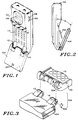
- Figure 1 is an isometric drawing of a portable radiotelephone which may employ the present invention.
- Figure 2 is a side view of the portable radiotelephone of Figure 1 in which a foreign object may be trapped between the flip cover element and the user interface.
- Figure 3 is a diagram of the hookswitch mechanism which may be employed in the radiotelephone of Figure 1.
- Figure 4 is a schematic diagram of a slave microcomputer which may employ the present invention.
- Figure 5 is a schematic diagram of the master microcomputer which may employ the present invention.
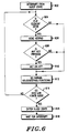
- Figure 6 is a flowchart of the deactivation process which may be employed in the present invention.
- Figure 7 is a flowchart of the master microcomputer process of deactivation employed in the present invention.
- Figures 8A and 8B, combined, are a flowchart of the slave microcomputer process of deactivation employed in the present invention.
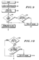
- Figure 9 is a flowchart of the master microcomputer process of activation/deactivation of the power switch upon initial power-up of the master microcomputer as employed in the present invention.
- Figure 10 is a flowchart of the activation/deactivation of the power switch after initial power-up of the master microcomputer as employed in the present invention.
- A portable radiotelephone adapted to be used in a cellular radiotelephone system is shown in Figure 1. This portable unit consists of two readily apparent portions, a
body portion 102 and aflip element portion 104. The drawing of Fig. 1 shows theflip element 104 in an "open" position such that a user of the portable unit may listen viaearpiece 106 and may speak into themicrophone 107. The dial orkeypad 110 consists of a plurality of buttons numbered one through zero, # and *, in familiar telephone arrangement as well as additional function buttons such as "send", "end", "on-off", and other buttons associated with memory recall. Disposed on the side of thebody portion 102 are two volume control buttons: volume increase 108 andvolume decrease 109, which may adjust the volume of the earpiece and/or the ringer. - When the
flip element 104 is open as shown in Fig. 1, the portable cellular telephone can be in the state of answering or making a telephone call. Such a state is commonly known as "off-hook". (It should be noted that in the cellular system an additional operator activity is required to place a call: upon entering a telephone number to be dialed, the send button must be depressed in order to activate the portable unit's transmitter and to complete the call. In the preferred embodiment, the send button may also be used to answer a call if the flip element is already open). Upon completion of the telephone call, the user may hang up the portable telephone (go "on-hook") by moving theflip element 104 into a stowed position, that is, rotated about the axis ofhinges flip element 104 rests nearly againstkeypad 110. This action activates a hookswitch (HKS) which causes the telephone call to be terminated. Depression of the end button without closing the flip element may also terminate the call. - Activation of the hookswitch occurs in the preferred embodiment when the angle between the
body 102 and theflip element 104 equals approximately 45o. The closing of theflip element 104 can best be perceived in Fig. 2. It can be imagined that should aforeign object 202 become lodged between theflip element 104 and thebody 102, undesired key depressions ofkeypad 110 might occur. - The hookswitch in the preferred embodiment is located between the
flip element 104 and thebody portion 102 and may be seen in the detail of Fig. 3. Acontact 302 consisting of a conventional conductive spring material is disposed inhinge 114 offlip element 104 and rotates with theflip element 104. A printedcircuit board element 304 is disposed in thebody portion 102 in a position such that thecontact 302 presses against thecircuit board element 304. Metalization disposed on printedcircuit board element 304 is positioned such that when theflip element 104 is opened to an angle of 45o, an electrical connection is completed between the metalization through thecontact 302 to ground. The combination of thecontact 302 and the printedcircuit board element 304 is the hookswitch (HKS) 306. - In the preferred embodiment, two interconnected microcomputer systems are utilized to control the basic functions of the portable unit (the master microcomputer) and to control the key pad and display functions (the slave microcomputer). The slave microcomputer is shown in the schematic of Fig. 4. The slave microcomputer system consists of a
microprocessor 402 which, in the preferred embodiment, is an MC68HC05C4 microprocessor (which also has on-board memory). The basic function of the slave microprocessor is to provide interface to the user of the portable radiotelepone via keyboard, display, and other buttons and indicators. The slave microprocessor is coupled to amulti-segment display 404 which, in the preferred embodiment, is a conventional LED eight digit display. Theslave microprocessor 402 is also coupled to a keypad matrix ofbuttons 110′ which enables the portable radiotelephone user to input (dial) telephone numbers, store and recall telephone number information, and perform other radiotelephone functions (such as initiating a telephone call). In the preferred embodiment, one of thekeys 408 of thematrix 110′ is specially dedicated to the function of turning the power on and off. Power on/off is accomplished by a momentary switch closure (by key 408) to ground which activates on/off circuitry.Volume increase switch 108′ andvolume decrease switch 109′ are electrically coupled to theslave microprocessor 402 as part of the row/column matrix. Their physical location is away from thekeypad 110 to allow for greater user convenience. - The function which is normally performed by a hookswitch in a conventional landline telephone is performed in the portable radiotelephone of the present invention as previously described in relation to Fig. 3. The hookswitch is shown schematically as
switch 306 in Fig. 4. A DC (Direct Current) circuit is made or broken byHKS 306 to ground and applied tomicroprocessor 402. Furthermore, a pulse is generated from any change of state of theHKS 306 by atransistor 410capacitors 412 and 414 andresistors transistor 410 is taken from the collector and applied to the interrupt request (IRQ) input and the keypad column inputs ofmicroprocessor 402 having a negative duration of approximately 10 microseconds.Microprocessor 402 stores the status ofHKS 306 and provides an indication of the change of state ofHKS 306 to the master microprocessor. - Communication between the
slave microprocessor 402 and the master microprocessor is maintained on adata bus 420. Thisdata bus 420 is coupled to themaster microprocessor 502 as shown in Fig. 5 of the master microcomputer. Other functions also share the data bus 420: theportable radiotelephone transceiver 504 accepts radio channel synthesizer information and message encoding/decoding from thebus 420, and specialized watchdog functions 506 operate from instructions given onbus 420. In the preferred embodiment, master microprocessor is realized by a conventional 68HC11 microprocessor. The remainder of the microcomputer associated withmicroprocessor 502 consists ofmemory 508, which in the preferred embodiment may be a plurality of conventional RAMS, EPROMS, and/or EEPROMS, and a specialized power controller 510 which performs the functions of turning on and off the several different voltages required by the different portable transceiver functions, as well as conditioning the on/off signal. In order to aid in the understanding of the operation of the present invention, peripheral power switching circuits such as external power sensing and memory keep-alive are omitted from Fig. 5 and the descriptive text. - Assuming that the portable radiotelephone has been powered-up and the flip element has been opened to enable the HKS, a
keypad 110 pushbutton activation by the portable radiotelepone user results in a communication between theslave microprocessor 402 and themaster microprocessor 502 via thebus 420. Theslave microprocessor 402, in the preferred embodiment, communicates that a closure has occurred between a particular row and a particular column corresponding to the key pressed by the user. Themaster microprocessor 502 may then take the appropriate action, such as returning a digit instruction viabus 420 for theslave microprocessor 402 to cause thedisplay 404 to illuminate or otherwise display. Thus, theslave micorprocessor 402 is commanded by themaster microprocessor 502 or the user in order to complete an assignment. - When both the
slave microprocessor 402 and themaster microprocessor 502 operate together, the process shown in Fig. 6 is that which is followed to determine if the keypad keys and control switches should cause a response by the portable radiotelephone. Since it is an important feature of the present invention to disable the user interface when the flip element is closed, this feature is incorporated into the process of Fig. 6. Although the preferred embodiment has been implemented employing two micrprocessors, this should not be a limitation of the invention for it is possible to implement the present invention in a single microprocessor should the designer so desire. For either a single microprocessor or a multiple microprocessor system, the microprocessors may be interrupt driven in order to save battery power. The process of Fig. 6, therefore, commences with an interrupt due to a change of state of the hookswitch 306 or a key closure fromkeypad 110 to enable the microcomputer system at 602. A determination is made, at 604, whether the flip element is open or closed. If the flip element is open, then thekeypad 110 is read to determine which key has been closed at 606. If a key has been depressed at 608, then the function or character designated by the key is acted upon at 610. If akeypad 110 key has not been depressed, then no action is taken and the microcomputer system resumes its normal functions of controlling the transceiver, the display, and other housekeeping chores as shown at 612. If it is determined that the flip element is not open (at 604), then any keypad key depression is considered to be spurious and is ignored by progressing directly from the determination block at 604 to the normal housekeeping functions block at 612. The entire process is repeated for a predetermined period of time until a determination is made that the microcomputer system should go into a low power consumption mode as deterined at 614. The microcomputer system is put into a "sleep" state at 616 and only the low power functions await for an interrupt signal at 618. - If the microcomputer system is implemented as a master and a slave microcomputer, then master microprocessor utilizes the process shown in Fig. 7 (as part of its standard operating procedure) to prevent spurious key depressions from activating the portable transceiver. Since the
slave microprocessor 402 can send either a flip element closed indication or a flip open indication, a detection of those indications is necessary by the master microcomputer. A test is made, at 702, of whether a flip element closed indication has been received from theslave microprocessor 402 on thebus 420. If a flip element closed indication is received, then themaster microprocessor 502 sends a keypad disable command, at 704, to theslave microprocessor 402 on thebus 420. The master microcomputer then returns to its programmed routine of chores. If a flip element closed indication is not received, at 702, then a test is made of whether a flip element open indication has been received from theslave microprocessor 402, at 706. If such an indication has been received by themaster microprocessor 502, then a command is sent to theslave microprocessor 402 on thebus 420 to enable theslave microprocessor 402 to again read any keypad button depressions and to send such information to themaster microprocessor 502. Upon completion of the enable command, themaster microprocessor 502 returns to its routine chores. - The process followed by the slave microcomputer in realizing the present invention in the preferred embodiment is shown in Figs. 8A and 8B. The
slave microprocessor 402 memorizes the state of the hookswitch 306 corresponding to whether the flip element is open or closed. Theslave microprocessor 402 determines, as part of its routine of chores, whether thehookswitch 306 has changed state by comparing the current state against the stored state at 802 and 804. If the state is different, then a determination is made, at 806, whether the flip element is open or closed. If the flip element is determined to be open, then an open flip element command is transmitted to the master microprocessor at 808. If the determination at 806 yields a closed flip element, then a closed flip element command is conveyed to the master microprocessor at 810. In either case themaster microprocessor 502 always maintains the flip element state in its associated storage. The slave microprocessor, as part of its routine of chores, checks for a keypad enable or a keypad disable command received from themaster microprocessor 502. This determination is made at decision blocks 812 and 814. A keypad enable command sets a keypad enable flag inmicroprocessor 402 memory at 816, while a keypad disable command clears the keypad enable flag at 818 before the process of Fig. 8 resumes its normal background flow. Further along the normal background process, theslave microprocessor 402 reads the keypad enable flag, at 820, and reads the row and column lines from the keypad in addition to thevolume increase switch 108 and thevolume decrease switch 109, at 822, to determine if any key or switch has been depressed (such determination made at 824). If a key or switch has been depressed, then an identification of the key or switch depression is sent to the master microprocessor at 826. The process of Fig. 8 then returns to the normal slave microprocessor background functions. Thus, if the flip element is determined to be open, then the keys of the keypad and the volume increase and decrease switches are read in conventional fashion. If the flip element is determined to be closed, then the keys of the keypad and the volume increase and decrease switches are ignored. There is, however, one further exception. - The on/off key is also covered and protected by the flip element. In the preferred embodiment, the on/off key is placed among the matrix of keypad keys for aesthetic reasons. It is a desirable feature that once the power is turned on, the portable transceiver remain in a power-on mode and not be turned off due to a spurious on/off key depression when the flip element is closed. Likewise, when the portable transceiver is turned off, it is equally desirable that the portable transceiver remain in the power-off condition even though a spurious on/off key depression may occur when the flip element is closed. Two processes enable this operation.
- Depressions of the on/off key are ignored when the flip element is closed. Referring again to Fig. 4, when a momentary depression of the on/off
switch 408 occurs, a ground is applied to the on/off line and to the power controller 510 of Fig. 5. The ground, applied throughswitch 408, is buffered by power controller 510 and applied to themaster microprocessor 502 vialine 512. Upon receipt of this buffered on/off signal online 512, themaster microprocessor 502 follows the process flowcharted in Fig. 9. Themaster microprocessor 502 and the rest of the associated microcomputer system undergoes a reset operation at 902 and requests a system characterization (a definition of what peripherals exist on the bus) at 904. As part of the characterization process, theslave microprocessor 402 reports the state of the flip element. The current flip element state is then stored, at 905. The master microprocessor then determines if the flip element is open, at 906. If this determination is positive, then the master microcomputer proceeds with its normal wake-up and housekeeping routines. If the flip element is determined to be closed at 906, then a check is made to determine if an external supply has been connected to the portable radiotelephone (at 908). Such a circuitry sharing arrangement is further described in U.S. Patent Application No. 107,227, "Radio Arrangement Having Two Radios Sharing Circuitry", filed on behalf of Michael P. Metroka on October 9, 1987. If an external supply is determined to exist at 908, then themaster microprocessor 502 returns to its normal housekeeping routines. If an external supply is not connected, then a power turn off routine is followed at 910. (Power turn off is accomplished by themaster microprocessosr 502 by storing its status and other essential parameters in memory before allowing the watchdog functions 506 of Fig. 5 to runout. A watchdog power function runout is communicated to the power controller 510 which subsequently turns off the portable radiotelephone). - Once the master microcomputer has successfully powered up, any on/off switch depressions are ignored so long as the flip element is closed (as shown in the process of Fig. 10). A determination of the signal sense on
line 512 of Fig. 5 is made by themaster microprocessor 502 at 1002. If the sense is a signal high, then the master microprocessor continues with its background routines. If the sense is low, then themaster microprocessor 502 reads the status of the flip element storage (at 1014) and either proceeds with a turn off routine (at 1016) if the flip element is open, or ignores a depression of the on/off switch as a spurious depression if the flip element is closed. Thus, a valid on/off command may be processed only if the flip element is open. - In summary, then, a portable radiotelephone having the capability of ignoring spurious control switch inputs has been shown and described. A flip element which covers a keypad and other control buttons when in a closed position also activates a hookswitch. When the hookswitch and microprocessor indicate that the flip element is in a closed position, the on/off switch cannot be activated to turn the portable radiotelephone on or off. Also, switches which control volume level are deactivated when the flip element is in the closed position. While a particular embodiment of the invention has been shown and described, it is to be understood that the invention is not to be taken as limited to the specific embodiment herein, and that changes and modifications may be made. It is contemplated therefore to cover the present invention, and any and all such changes and modifications, by the appended claims.
Claims (10)
- Portable radiotelephone apparatus operating from a switchable power source, the radiotelephone comprising processing means (402) for controlling operation of the portable radiotelephone apparatus, a user interface coupled to the processing means and disposed on an outer surface of the radiotelephone for affecting a supply of power from the switchable power source to the radiotelephone, a movable element (104) the movable between a first position and a second position and means (302, 114, 304, 306) for producing an on-hook condition in the processing means if the movable element is in the first position and for producing an off-hook condition in the processing means if the movable element is in the second position, the portable radiotelephone apparatus characterized by:
means (402, 502) for preventing the switchable power source from being switched from on to off and vice versa when the portable radiotelephone apparatus is in said produced on-hook condition by at least partially disabling the user interface (110), thereby preventing inadvertent discharge of a battery of the switchable power source if the switchable power source is switched off and preventing missing a call if the switchable power source is switched on. - Portable radiotelephone apparatus in accordance with claim 1, wherein said means (402, 502) for preventing further comprises means (408) for enabling the switchable power source to be turned on if the portable radiotelephone apparatus is in said off-hook condition.
- Portable radiotelephone apparatus in accordance with claim 2, wherein said means (402, 502) for enabling further comprises means for storing a movable element state signal to indicate said off-hook condition after said switchable power source has been switched on and wherein said means (402, 502) for preventing further comprises means for comparing said movable element state signal to an indication from said means (302, 304, 306) for producing to determine if the portable radiotelephone apparatus is on-hook.
- Portable radiotelephone apparatus in accordance with claim 1, 2 or 3, wherein said means for preventing further comprises means (408) for enabling the switchable power source to be switched off if the portable radiotelephone apparatus is in said off-hook condition.
- Portable radiotelephone apparatus in accordance with any preceding claim, further comprising means (108', 109') for preventing the adjustment of the acoustic volume of an acoustic transducer when the portable radiotelephone apparatus is in said produced on-hook condition.
- Portable radiotelephone apparatus operating from a switchable power source, the radiotelephone comprising processing means (402, 405) for controlling the operation of the portable radiotelephone apparatus, volume control keys (108,109) coupled to the processing means and disposed on an outer surface, and a movable element (104) movable between a first position and a second position, the portable radiotelephone apparatus operating from a switchable power source and having means (302, 114, 304, 306) for producing an on-hook condition in the processing means if the movable element is in the first position and for producing an off-hook condition in the processing means if the movable element is in the second position, the portable radiotelephone characterized by:
means (402, 502) for preventing adjustment of the acoustic volume of an acoustic transducer if the portable radiotelephone apparatus is in said produced on-hook condition by at least partially disabling the volume control keys, thereby preventing an undesired output of the acoustic transducer. - A method of preventing spurious switch operation in a portable radiotelephone operating from a switchable power source and having a user interface disposed on the outer surface of the radiotelephone for affecting a supply of power from the switchable power source to the radiotelephone and a movable element (104) movable between a first position and a second position, the method comprising the steps of: producing an off-hook condition in the portable radiotelephone apparatus when the movable element is in the first position and producing an off-hook condition in the portable radiotelephone when the movable element is in the second position; the method characterized by the step of:
preventing the switchable power source from being switched from on to off and vice versa when the portable radiotelephone is in said produced on-hook condition by at least partially disabling the user interface (110), thereby preventing inadvertent discharge of a battery of the portable radiotelephone apparatus if the switchable power source is switched off or preventing missing a call if the switchable power source is switched on. - A method of preventing spurious switch operation in a portable radiotelephone in accordance with claim 7, wherein the preventing step further comprises the step of enabling the switchable power source to be switched on when the portable radiotelephone apparatus is in said produced off-hook condition.
- A method of preventing spurious switch operation in a portable radiotelephone in accordance with claim 8, wherein the enabling step further includes the step of setting (816, 905) a movable element state signal to indicate said off-hook condition after said switchable power source has been switched on and wherein said preventing step further includes the step of comparing (906) said movable element state signal to an indication from said means for producing to determine if the portable radiotelephone apparatus is in said on-hook condition.
- A method of preventing spurious switch operation in a portable radiotelephone in accordance with claim 7, 8 or 9, wherein said preventing step further comprises the step of enabling the switchable power source to be switched off if the portable radiotelephone apparatus is in said off-hook condition.
Applications Claiming Priority (2)
| Application Number | Priority Date | Filing Date | Title |
|---|---|---|---|
| US206072 | 1988-06-13 | ||
| US07/206,072 US4845772A (en) | 1988-06-13 | 1988-06-13 | Portable radiotelephone with control switch disabling |
Publications (3)
| Publication Number | Publication Date |
|---|---|
| EP0346639A2 EP0346639A2 (en) | 1989-12-20 |
| EP0346639A3 EP0346639A3 (en) | 1991-05-29 |
| EP0346639B1 true EP0346639B1 (en) | 1996-08-28 |
Family
ID=22764859
Family Applications (1)
| Application Number | Title | Priority Date | Filing Date |
|---|---|---|---|
| EP89109012A Expired - Lifetime EP0346639B1 (en) | 1988-06-13 | 1989-05-19 | Portable radiotelephone with control switch disabling |
Country Status (18)
| Country | Link |
|---|---|
| US (1) | US4845772A (en) |
| EP (1) | EP0346639B1 (en) |
| JP (1) | JPH0244843A (en) |
| KR (1) | KR920009398B1 (en) |
| AT (1) | ATE142068T1 (en) |
| AU (1) | AU610416B2 (en) |
| BR (1) | BR8906967A (en) |
| CA (1) | CA1296774C (en) |
| DE (1) | DE68927024T2 (en) |
| DK (1) | DK30190A (en) |
| ES (1) | ES2091189T3 (en) |
| FI (1) | FI104031B1 (en) |
| HK (1) | HK1008132A1 (en) |
| IE (1) | IE61916B1 (en) |
| IL (1) | IL90261A (en) |
| MX (1) | MX165350B (en) |
| SG (1) | SG86299A1 (en) |
| WO (1) | WO1989012945A1 (en) |
Families Citing this family (121)
| Publication number | Priority date | Publication date | Assignee | Title |
|---|---|---|---|---|
| US6545589B1 (en) | 1984-09-14 | 2003-04-08 | Aspect Communications Corporation | Method and apparatus for managing telecommunications |
| US5375161A (en) | 1984-09-14 | 1994-12-20 | Accessline Technologies, Inc. | Telephone control system with branch routing |
| US5752191A (en) | 1984-09-14 | 1998-05-12 | Accessline Technologies, Inc. | Telephone control system which connects a caller with a subscriber AT A telephone address |
| US4687247A (en) * | 1985-05-13 | 1987-08-18 | Muscat Peter P | Powered tonneau cover for convertible automobiles |
| US5014346A (en) * | 1988-01-04 | 1991-05-07 | Motorola, Inc. | Rotatable contactless antenna coupler and antenna |
| JPH077996B2 (en) * | 1988-05-23 | 1995-01-30 | 日本電気株式会社 | Telephone separation detection circuit |
| US4897873A (en) * | 1988-11-04 | 1990-01-30 | Motorola, Inc. | Multipurpose hinge apparatus for foldable telephones |
| US5259018A (en) * | 1989-03-17 | 1993-11-02 | Technophone Limited | Radio telephone system having a handset adapted to be removably connected and containing a NAM for storing a telephone number identifying the handset |
| US5175759A (en) * | 1989-11-20 | 1992-12-29 | Metroka Michael P | Communications device with movable element control interface |
| US5148471A (en) * | 1989-11-20 | 1992-09-15 | Motorola, Inc. | Communications device with voice recognition and movable element control interface |
| WO1991013507A1 (en) * | 1990-02-27 | 1991-09-05 | Fujitsu Limited | Portable telephone |
| DE69105221T2 (en) * | 1990-03-07 | 1995-06-08 | Sony Corp | Radio telephone set. |
| GB2243117B (en) * | 1990-04-20 | 1994-04-20 | Technophone Ltd | Portable radio telephone |
| JPH0491541A (en) * | 1990-08-07 | 1992-03-25 | Fujitsu Ltd | Handset for telephone set |
| JP2856263B2 (en) * | 1990-09-07 | 1999-02-10 | 富士通株式会社 | Mobile phone |
| WO1992017974A1 (en) * | 1991-03-28 | 1992-10-15 | Motorola, Inc. | Hinge apparatus for foldable radiotelephones |
| US5185790A (en) * | 1991-03-28 | 1993-02-09 | Motorola, Inc. | Multiposition detenting hinge apparatus |
| US5259019A (en) * | 1991-04-08 | 1993-11-02 | Texas Instruments Incorporated | Apparatus providing for a curved device with hinged cover |
| US5815820A (en) * | 1991-07-12 | 1998-09-29 | Motorola, Inc. | Transmitter having adjustable power levels responsive to the position of a movable antenna |
| US5898933A (en) * | 1991-07-12 | 1999-04-27 | Motorola, Inc. | Apparatus and method for generating a control signal responsive to a movable antenna |
| US5280635A (en) * | 1991-09-04 | 1994-01-18 | Gerry Baby Products Company | Baby monitor transmitter |
| US5337346A (en) * | 1991-09-26 | 1994-08-09 | Casio Computer Co., Ltd. | Portable telephone apparatus including electronic notebook function |
| US5276916A (en) * | 1991-10-08 | 1994-01-04 | Motorola, Inc. | Communication device having a speaker and microphone |
| US5265264A (en) * | 1991-12-23 | 1993-11-23 | Motorola, Inc. | Convertible half-to-full duplex radio operation selected by battery |
| JPH0661910A (en) * | 1992-04-21 | 1994-03-04 | Nec Corp | Portable telephony5 equipment |
| JP3268467B2 (en) * | 1992-09-08 | 2002-03-25 | 株式会社日立製作所 | Telephone |
| JP2743738B2 (en) * | 1992-10-21 | 1998-04-22 | 日本電気株式会社 | Radio selective call receiver |
| US5826201A (en) * | 1992-11-25 | 1998-10-20 | Asterion, Inc. | Antenna microwave shield for cellular telephone |
| US5404582A (en) * | 1992-11-27 | 1995-04-04 | Motorola, Inc. | Aural annunciator circuit for a receiver |
| US5907615A (en) * | 1992-12-02 | 1999-05-25 | Motorola, Inc. | Miniature wireless communication device |
| US5465401A (en) * | 1992-12-15 | 1995-11-07 | Texas Instruments Incorporated | Communication system and methods for enhanced information transfer |
| US5335366A (en) * | 1993-02-01 | 1994-08-02 | Daniels John J | Radiation shielding apparatus for a radio transmitting device |
| US5666125A (en) * | 1993-03-17 | 1997-09-09 | Luxon; Norval N. | Radiation shielding and range extending antenna assembly |
| FR2703203B1 (en) * | 1993-03-23 | 1995-04-28 | Alcatel Radiotelephone | Compact portable radiotelephone terminal. |
| US5461664A (en) * | 1993-04-07 | 1995-10-24 | Cappadona; Steven | Emergency wireless telephone |
| US5384844A (en) * | 1993-07-30 | 1995-01-24 | Ericsson Ge Mobile Communications, Inc. | Pivotable housing for hand-held transceiver |
| US5548824A (en) * | 1993-08-25 | 1996-08-20 | Mitsubishi Denki Kabushiki Kaisha | Portable radio communication device housing having a battery storage unit |
| US5574772A (en) * | 1993-11-01 | 1996-11-12 | Scalisi; Joseph F. | Personal apparatus for receiving radiotelephone communications |
| CN1042687C (en) * | 1993-11-08 | 1999-03-24 | 摩托罗拉公司 | Electronic device coupling apparatus |
| JPH07143214A (en) * | 1993-11-19 | 1995-06-02 | Sony Corp | Portable telephone set |
| JPH07154840A (en) * | 1993-11-26 | 1995-06-16 | Casio Comput Co Ltd | Radio receiver |
| GB2285195B (en) * | 1993-12-22 | 1997-04-23 | Nokia Mobile Phones Ltd | Telephone handset |
| US5507013A (en) * | 1994-05-23 | 1996-04-09 | Ericsson Ge Mobile Communications, Inc. | Preferential deflection hinged housing configuration |
| JP2891873B2 (en) * | 1994-05-24 | 1999-05-17 | 日本電気株式会社 | Wireless device and power control method thereof |
| JP2550914B2 (en) * | 1994-06-21 | 1996-11-06 | 日本電気株式会社 | Foldable mobile phone device |
| US6587700B1 (en) * | 1994-06-23 | 2003-07-01 | At&T Wireless Services, Inc. | Personal communicator with flip element display |
| US6095820A (en) * | 1995-10-27 | 2000-08-01 | Rangestar International Corporation | Radiation shielding and range extending antenna assembly |
| EP0726657A4 (en) * | 1994-08-31 | 1999-01-27 | Sony Corp | Communication terminal |
| US5542105A (en) * | 1994-10-07 | 1996-07-30 | Motorola, Inc. | Position sense radio carry case apparatus and method of using same |
| AU4502596A (en) * | 1994-11-28 | 1996-06-19 | Ericsson Inc. | Portable telephone with an asymmetric hinged housing configuration |
| US5732331A (en) * | 1995-01-12 | 1998-03-24 | Ericsson Inc. | Portable radio having a detachable flip portion |
| JP3550207B2 (en) * | 1995-03-01 | 2004-08-04 | 富士通株式会社 | Mode switching telephone and mode setting method in the telephone |
| JPH08340565A (en) * | 1995-06-13 | 1996-12-24 | Nec Shizuoka Ltd | Selective call radio receiver with protection cover |
| US5959260A (en) * | 1995-07-20 | 1999-09-28 | Motorola, Inc. | Method for entering handwritten information in cellular telephones |
| KR0144390B1 (en) * | 1995-08-16 | 1998-08-01 | 김광호 | Multi-function telephone set |
| JP3086641B2 (en) * | 1995-08-29 | 2000-09-11 | 三洋電機株式会社 | Mobile terminal |
| US5848152A (en) * | 1995-09-26 | 1998-12-08 | Motorola, Inc. | Communication device having interchangeable faceplates and active keypad cover |
| US5812954A (en) * | 1995-11-27 | 1998-09-22 | Nokia Mobile Phones Ltd. | Mobile telephone power key lock function |
| GB2310568B (en) | 1996-02-26 | 1999-10-20 | Nokia Mobile Phones Ltd | Radio telephone |
| DE69736059T2 (en) | 1996-02-26 | 2006-11-09 | Nokia Corp. | WIRELESS PHONE |
| US5767778A (en) * | 1996-03-06 | 1998-06-16 | Aspire Corporation | Event sensing circuit and alert generator |
| US5809403A (en) * | 1996-03-11 | 1998-09-15 | Erisson Inc. | Coaxial cable assembly for a portable phone |
| US5732144A (en) * | 1996-07-01 | 1998-03-24 | Motorola, Inc. | Remote microphone display select system and method of using same |
| US6073027A (en) * | 1996-08-29 | 2000-06-06 | Bellsouth Corporation | Portable radiotelephone with sliding cover and automatic antenna extension |
| US6035211A (en) * | 1996-12-19 | 2000-03-07 | Ericsson Inc. | Dual use speaker for both voice communication and signalling |
| US5987311A (en) * | 1996-12-27 | 1999-11-16 | Ericsson Inc. | Apparatus for enabling a keypad in response to antenna extension |
| US8466795B2 (en) | 1997-01-21 | 2013-06-18 | Pragmatus Mobile LLC | Personal security and tracking system |
| US6128514A (en) | 1997-01-31 | 2000-10-03 | Bellsouth Corporation | Portable radiotelephone for automatically dialing a central voice-activated dialing system |
| JP4129698B2 (en) * | 1997-06-19 | 2008-08-06 | テレフオンアクチーボラゲット エル エム エリクソン(パブル) | Apparatus and method with mobile transceiver |
| US5956398A (en) * | 1997-07-11 | 1999-09-21 | Ericsson Inc. | Telephone switching mechanism |
| US6101402A (en) * | 1997-09-04 | 2000-08-08 | Ericcson Inc. | Radiotelephone with sliding acoustic member |
| US6011699A (en) * | 1997-10-15 | 2000-01-04 | Motorola, Inc. | Electronic device including apparatus and method for routing flexible circuit conductors |
| US6352434B1 (en) | 1997-10-15 | 2002-03-05 | Motorola, Inc. | High density flexible circuit element and communication device using same |
| CN1288631A (en) * | 1998-01-20 | 2001-03-21 | 夸尔柯姆股份有限公司 | Apparatus and method for prevention of accidental activation of keys in a wireless communication device |
| SE514237C2 (en) | 1998-02-26 | 2001-01-29 | Ericsson Telefon Ab L M | Interchangeable connector for mutually rotating units and a portable device provided with such connector |
| GB2334850A (en) | 1998-02-27 | 1999-09-01 | Nokia Mobile Phones Ltd | A communication device with a keyboard cover mounted upon sliding rods |
| US6115620A (en) * | 1998-05-20 | 2000-09-05 | Motorola, Inc. | Mode-switchable portable communication device and method therefor |
| SE9801970L (en) * | 1998-06-03 | 1999-12-04 | Ericsson Telefon Ab L M | Mobile electronic device |
| DE29809959U1 (en) * | 1998-06-04 | 1998-08-13 | Schroeder Udo | Mobile phone to make an emergency call |
| USD408402S (en) * | 1998-08-18 | 1999-04-20 | Motorola, Inc. | Cellular telephone housing |
| US7274928B2 (en) * | 1998-10-02 | 2007-09-25 | Telespree Communications | Portable cellular phone system having automatic initialization |
| US6167251A (en) * | 1998-10-02 | 2000-12-26 | Telespree Communications | Keyless portable cellular phone system having remote voice recognition |
| JP2000270067A (en) * | 1999-03-16 | 2000-09-29 | Nec Corp | Portable telephone set |
| FR2791508B1 (en) * | 1999-03-22 | 2001-06-08 | Cit Alcatel | PORTABLE TELEPHONE WITH ARTICULATED SHUTTER IN RELATION TO THE HOUSING |
| FI991007A (en) | 1999-05-03 | 2000-11-04 | Nokia Mobile Phones Ltd | An electronic device with a sheath |
| JP3334681B2 (en) * | 1999-06-08 | 2002-10-15 | 日本電気株式会社 | Wireless terminal and control method in wireless terminal |
| USD424557S (en) * | 1999-06-18 | 2000-05-09 | Motorola, Inc. | Cellular telephone housing |
| USD419155S (en) * | 1999-07-01 | 2000-01-18 | Motorola, Inc. | Cellular telephone housing |
| US6418325B1 (en) * | 1999-07-12 | 2002-07-09 | Motorola, Inc. | Handheld device having an optical data reader |
| GB2353170A (en) | 1999-08-06 | 2001-02-14 | Nokia Mobile Phones Ltd | Slide assembly for a communication unit |
| JP3448547B2 (en) * | 2000-05-12 | 2003-09-22 | 三洋電機株式会社 | Foldable mobile phone |
| KR200211457Y1 (en) * | 2000-08-08 | 2001-01-15 | 엘지정보통신주식회사 | Flip type Mobile station |
| JP3707417B2 (en) * | 2000-10-30 | 2005-10-19 | 日本電気株式会社 | Mobile terminal having dial lock function |
| US6456487B1 (en) * | 2001-04-30 | 2002-09-24 | Nokia Corporation | Enclosure for wireless communication device |
| US6886245B1 (en) * | 2001-11-09 | 2005-05-03 | Nokia Corporation | Method for manufacturing mobile electronic devices using a common engine assembly |
| US20030129950A1 (en) * | 2002-01-10 | 2003-07-10 | Min-Woo Kwak | Antenna of wireless phone |
| US8046581B2 (en) * | 2002-03-04 | 2011-10-25 | Telespree Communications | Method and apparatus for secure immediate wireless access in a telecommunications network |
| US7197301B2 (en) * | 2002-03-04 | 2007-03-27 | Telespree Communications | Method and apparatus for secure immediate wireless access in a telecommunications network |
| EP1481561A1 (en) * | 2002-03-04 | 2004-12-01 | Nokia Corporation | Method for intermediate unlocking of a keypad on a mobile electronic device |
| US7257430B2 (en) * | 2002-05-11 | 2007-08-14 | Motorola, Inc. | Self configuring multiple element portable electronic device |
| US6927555B2 (en) * | 2002-06-13 | 2005-08-09 | Motorola, Inc. | Sleep mode batteries in electronics devices and methods therefor |
| JP3961397B2 (en) * | 2002-10-29 | 2007-08-22 | 京セラ株式会社 | Mobile terminal device |
| USD493436S1 (en) | 2003-01-21 | 2004-07-27 | Matsushita Electric Industrial Co., Ltd. | Mobile phone |
| USD493437S1 (en) | 2003-01-31 | 2004-07-27 | Matsushita Electric Industrial Co., Ltd. | Mobile phone |
| USD488791S1 (en) | 2003-06-17 | 2004-04-20 | Matsushita Electric Industrial Co., Ltd. | Mobile phone |
| USD487071S1 (en) | 2003-06-17 | 2004-02-24 | Matsushita Electric Industrial Co., Ltd. | Mobile phone |
| USD487736S1 (en) | 2003-06-17 | 2004-03-23 | Matsushita Electric Industrial Co., Ltd. | Mobile phone |
| US20040263485A1 (en) * | 2003-06-27 | 2004-12-30 | Chi-Yu Ho | [hand-held apparatus with the touch control device] |
| US7046799B2 (en) * | 2003-09-12 | 2006-05-16 | Motorola, Inc. | Communication headset and method |
| US20050088513A1 (en) * | 2003-10-24 | 2005-04-28 | Oswald Gary J. | Open-to-view video telephony call in a wireless communication device |
| US7774029B2 (en) * | 2004-07-10 | 2010-08-10 | Samsung Electronics Co., Ltd. | Apparatus and method for controlling a function of a wireless terminal |
| US20060035677A1 (en) * | 2004-08-11 | 2006-02-16 | Naveen Aerrabotu | Disablement of external keys in a communication device |
| WO2006126170A2 (en) * | 2005-05-25 | 2006-11-30 | Nxp B.V. | A method of powering up a terminal, memory and terminal thereof |
| TWI314604B (en) * | 2006-09-19 | 2009-09-11 | Asustek Comp Inc | Electronic device |
| US7642933B2 (en) * | 2006-11-30 | 2010-01-05 | Motorola, Inc. | Methods and devices for keypress validation in a slider form factor device |
| JP4823163B2 (en) | 2007-07-23 | 2011-11-24 | 富士通東芝モバイルコミュニケーションズ株式会社 | Information processing device |
| US8208979B2 (en) * | 2008-03-04 | 2012-06-26 | Research In Motion Limited | System and method for handling open and close events in a mobile communication device |
| US20100151911A1 (en) * | 2008-11-26 | 2010-06-17 | Anthony W. Mazzeo | Integrated telecommunications handset |
| DE102009057958A1 (en) * | 2009-12-11 | 2011-06-16 | Swissphone Telecom Ag | Terminal for a telecommunications network |
| JP5503676B2 (en) * | 2012-03-05 | 2014-05-28 | 東芝テック株式会社 | Order terminal |
| ITVI20120345A1 (en) | 2012-12-28 | 2014-06-29 | Pizzato Elettrica Srl | ELECTRONIC SAFETY HINGE SWITCH |
Family Cites Families (17)
| Publication number | Priority date | Publication date | Assignee | Title |
|---|---|---|---|---|
| BE631733A (en) * | 1962-05-04 | |||
| US3705959A (en) * | 1971-05-17 | 1972-12-12 | Bell Telephone Labor Inc | Line lockout circuit |
| US3852541A (en) * | 1973-08-10 | 1974-12-03 | E Altenberger | Burglar alarm actuated by cut telephone wire |
| US3896270A (en) * | 1973-12-07 | 1975-07-22 | Gte Automatic Electric Lab Inc | Ringing signal detector circuit |
| DE2504314A1 (en) * | 1975-02-03 | 1976-08-05 | Elmeg | MESSAGE PERIPHERAL DEVICE, IN PARTICULAR TELEPHONE SET OR TEST HANDSET |
| GB2070392B (en) * | 1980-02-14 | 1984-03-14 | Standard Telephones Cables Ltd | Personal communications unit |
| JPS5832552A (en) * | 1981-08-21 | 1983-02-25 | Kawasaki Steel Corp | Mold for continuous casting of thin walled ingot |
| JPS59100659A (en) * | 1982-11-30 | 1984-06-09 | Sharp Corp | Wireless phone |
| US4471493A (en) * | 1982-12-16 | 1984-09-11 | Gte Automatic Electric Inc. | Wireless telephone extension unit with self-contained dipole antenna |
| JPS59135960A (en) * | 1983-01-25 | 1984-08-04 | Fujitsu Ltd | Hook switch changeover device of folded type handset in telephone set or the like |
| DE3309832A1 (en) * | 1983-03-18 | 1984-09-20 | Siemens Ag | WIRELESS PHONE |
| DE3323858A1 (en) * | 1983-07-01 | 1985-01-03 | Erwin Brandenstein | Cordless telephone device |
| JPS60230723A (en) * | 1984-04-27 | 1985-11-16 | エルヴイン・ブランデンシユタイン | Radio wave telephone set |
| JPS617145U (en) * | 1984-06-19 | 1986-01-17 | 株式会社 フオンランド | telephone receiver |
| JPS62209930A (en) * | 1986-03-10 | 1987-09-16 | Fujitsu Ltd | Erroneous action preventing system for portable radio terminal equipment |
| JPS63129755A (en) * | 1986-11-19 | 1988-06-02 | Matsushita Electric Ind Co Ltd | Portable telephone system |
| ATE92697T1 (en) * | 1987-01-23 | 1993-08-15 | Siemens Ag | TELEPHONE HANDSET BODY WITH A LOCKABLE CONTROL DEVICE FLAP. |
-
1988
- 1988-06-13 US US07/206,072 patent/US4845772A/en not_active Expired - Lifetime
-
1989
- 1989-03-29 MX MX016238A patent/MX165350B/en unknown
- 1989-05-08 CA CA000599012A patent/CA1296774C/en not_active Expired - Lifetime
- 1989-05-11 IL IL90261A patent/IL90261A/en unknown
- 1989-05-18 WO PCT/US1989/002118 patent/WO1989012945A1/en active IP Right Grant
- 1989-05-18 AU AU37411/89A patent/AU610416B2/en not_active Ceased
- 1989-05-18 KR KR1019900700259A patent/KR920009398B1/en not_active IP Right Cessation
- 1989-05-18 BR BR898906967A patent/BR8906967A/en not_active IP Right Cessation
- 1989-05-19 DE DE68927024T patent/DE68927024T2/en not_active Expired - Lifetime
- 1989-05-19 EP EP89109012A patent/EP0346639B1/en not_active Expired - Lifetime
- 1989-05-19 ES ES89109012T patent/ES2091189T3/en not_active Expired - Lifetime
- 1989-05-19 AT AT89109012T patent/ATE142068T1/en not_active IP Right Cessation
- 1989-05-19 SG SG9604709A patent/SG86299A1/en unknown
- 1989-06-12 IE IE187189A patent/IE61916B1/en not_active IP Right Cessation
- 1989-06-13 JP JP1148546A patent/JPH0244843A/en active Granted
-
1990
- 1990-02-06 DK DK030190A patent/DK30190A/en not_active Application Discontinuation
- 1990-02-08 FI FI900621A patent/FI104031B1/en not_active IP Right Cessation
-
1998
- 1998-06-27 HK HK98107187A patent/HK1008132A1/en not_active IP Right Cessation
Also Published As
| Publication number | Publication date |
|---|---|
| US4845772A (en) | 1989-07-04 |
| ATE142068T1 (en) | 1996-09-15 |
| IE61916B1 (en) | 1994-11-30 |
| WO1989012945A1 (en) | 1989-12-28 |
| IL90261A0 (en) | 1989-12-15 |
| ES2091189T3 (en) | 1996-11-01 |
| FI104031B (en) | 1999-10-29 |
| CA1296774C (en) | 1992-03-03 |
| EP0346639A2 (en) | 1989-12-20 |
| DE68927024T2 (en) | 1997-03-06 |
| FI900621A0 (en) | 1990-02-08 |
| JPH0544217B2 (en) | 1993-07-05 |
| KR920009398B1 (en) | 1992-10-16 |
| MX165350B (en) | 1992-11-05 |
| HK1008132A1 (en) | 1999-04-30 |
| DK30190A (en) | 1990-03-27 |
| KR900702738A (en) | 1990-12-08 |
| IE891871L (en) | 1989-12-13 |
| EP0346639A3 (en) | 1991-05-29 |
| SG86299A1 (en) | 2002-02-19 |
| JPH0244843A (en) | 1990-02-14 |
| BR8906967A (en) | 1990-12-11 |
| AU610416B2 (en) | 1991-05-16 |
| FI104031B1 (en) | 1999-10-29 |
| DE68927024D1 (en) | 1996-10-02 |
| IL90261A (en) | 1993-05-13 |
| AU3741189A (en) | 1990-01-12 |
| DK30190D0 (en) | 1990-02-06 |
Similar Documents
| Publication | Publication Date | Title |
|---|---|---|
| EP0346639B1 (en) | Portable radiotelephone with control switch disabling | |
| AU626487B2 (en) | Communications device with movable element control interface | |
| AU626475B2 (en) | Communications device with voice recognition and movable element control interface | |
| US5898933A (en) | Apparatus and method for generating a control signal responsive to a movable antenna | |
| KR0127759B1 (en) | Portable radio telephone | |
| EP0510809B1 (en) | Radio telephone | |
| KR19980019097A (en) | Communication Device and Display Blanking Control Method Therefor | |
| KR20000075737A (en) | A portable communication device and a method of performing multiple functions via power key of the same | |
| KR100331316B1 (en) | Method for controlling the liquid crystal display(LCD) and backlight of mobile phone using touch method and mobile phone therefor | |
| KR100365612B1 (en) | Circuit and method for automatically detecting valid key pressing in mobile communication terminal | |
| JPH04259156A (en) | Portable telephone set | |
| KR19990047354A (en) | Mobile phone operation control method having dual antenna and its device | |
| KR20050019174A (en) | Method of controlling LCD power in a cellular phone with LCD touch screen and cellular phone for the same | |
| KR200266290Y1 (en) | Switching apparatus for cellular phone onto hands-free mode | |
| JPH066296A (en) | Cordless system | |
| KR19980028640U (en) | Wired / wireless combined telephone with power saving function |
Legal Events
| Date | Code | Title | Description |
|---|---|---|---|
| PUAI | Public reference made under article 153(3) epc to a published international application that has entered the european phase |
Free format text: ORIGINAL CODE: 0009012 |
|
| AK | Designated contracting states |
Kind code of ref document: A2 Designated state(s): AT BE CH DE ES FR GB GR IT LI LU NL SE |
|
| PUAL | Search report despatched |
Free format text: ORIGINAL CODE: 0009013 |
|
| AK | Designated contracting states |
Kind code of ref document: A3 Designated state(s): AT BE CH DE ES FR GB GR IT LI LU NL SE |
|
| 17P | Request for examination filed |
Effective date: 19910705 |
|
| 17Q | First examination report despatched |
Effective date: 19930806 |
|
| GRAH | Despatch of communication of intention to grant a patent |
Free format text: ORIGINAL CODE: EPIDOS IGRA |
|
| GRAH | Despatch of communication of intention to grant a patent |
Free format text: ORIGINAL CODE: EPIDOS IGRA |
|
| GRAA | (expected) grant |
Free format text: ORIGINAL CODE: 0009210 |
|
| ITF | It: translation for a ep patent filed |
Owner name: BARZANO' E ZANARDO ROMA S.P.A. |
|
| AK | Designated contracting states |
Kind code of ref document: B1 Designated state(s): AT BE CH DE ES FR GB GR IT LI LU NL SE |
|
| PG25 | Lapsed in a contracting state [announced via postgrant information from national office to epo] |
Ref country code: GR Free format text: LAPSE BECAUSE OF FAILURE TO SUBMIT A TRANSLATION OF THE DESCRIPTION OR TO PAY THE FEE WITHIN THE PRESCRIBED TIME-LIMIT Effective date: 19960828 Ref country code: CH Effective date: 19960828 Ref country code: LI Effective date: 19960828 Ref country code: BE Effective date: 19960828 |
|
| REF | Corresponds to: |
Ref document number: 142068 Country of ref document: AT Date of ref document: 19960915 Kind code of ref document: T |
|
| REF | Corresponds to: |
Ref document number: 68927024 Country of ref document: DE Date of ref document: 19961002 |
|
| REG | Reference to a national code |
Ref country code: ES Ref legal event code: FG2A Ref document number: 2091189 Country of ref document: ES Kind code of ref document: T3 |
|
| ET | Fr: translation filed | ||
| REG | Reference to a national code |
Ref country code: CH Ref legal event code: PL |
|
| PG25 | Lapsed in a contracting state [announced via postgrant information from national office to epo] |
Ref country code: AT Free format text: LAPSE BECAUSE OF NON-PAYMENT OF DUE FEES Effective date: 19970519 |
|
| PG25 | Lapsed in a contracting state [announced via postgrant information from national office to epo] |
Ref country code: LU Free format text: LAPSE BECAUSE OF NON-PAYMENT OF DUE FEES Effective date: 19970531 |
|
| PLBE | No opposition filed within time limit |
Free format text: ORIGINAL CODE: 0009261 |
|
| STAA | Information on the status of an ep patent application or granted ep patent |
Free format text: STATUS: NO OPPOSITION FILED WITHIN TIME LIMIT |
|
| 26N | No opposition filed | ||
| PG25 | Lapsed in a contracting state [announced via postgrant information from national office to epo] |
Ref country code: NL Effective date: 19971201 |
|
| NLV4 | Nl: lapsed or anulled due to non-payment of the annual fee |
Effective date: 19971201 |
|
| REG | Reference to a national code |
Ref country code: GB Ref legal event code: IF02 |
|
| PGFP | Annual fee paid to national office [announced via postgrant information from national office to epo] |
Ref country code: ES Payment date: 20080528 Year of fee payment: 20 Ref country code: DE Payment date: 20080530 Year of fee payment: 20 |
|
| PGFP | Annual fee paid to national office [announced via postgrant information from national office to epo] |
Ref country code: IT Payment date: 20080514 Year of fee payment: 20 |
|
| PGFP | Annual fee paid to national office [announced via postgrant information from national office to epo] |
Ref country code: SE Payment date: 20080505 Year of fee payment: 20 |
|
| PGFP | Annual fee paid to national office [announced via postgrant information from national office to epo] |
Ref country code: GB Payment date: 20080407 Year of fee payment: 20 |
|
| REG | Reference to a national code |
Ref country code: GB Ref legal event code: PE20 Expiry date: 20090518 |
|
| EUG | Se: european patent has lapsed | ||
| REG | Reference to a national code |
Ref country code: ES Ref legal event code: FD2A Effective date: 20090520 |
|
| PG25 | Lapsed in a contracting state [announced via postgrant information from national office to epo] |
Ref country code: ES Free format text: LAPSE BECAUSE OF EXPIRATION OF PROTECTION Effective date: 20090520 |
|
| PG25 | Lapsed in a contracting state [announced via postgrant information from national office to epo] |
Ref country code: GB Free format text: LAPSE BECAUSE OF EXPIRATION OF PROTECTION Effective date: 20090518 |
|
| PGFP | Annual fee paid to national office [announced via postgrant information from national office to epo] |
Ref country code: FR Payment date: 20080424 Year of fee payment: 20 |
|
| P01 | Opt-out of the competence of the unified patent court (upc) registered |
Effective date: 20230520 |