EP0341483A2 - Device for measuring and processing spectra of proper fluorescence from surfaces of organic tissues - Google Patents
Device for measuring and processing spectra of proper fluorescence from surfaces of organic tissues Download PDFInfo
- Publication number
- EP0341483A2 EP0341483A2 EP89107440A EP89107440A EP0341483A2 EP 0341483 A2 EP0341483 A2 EP 0341483A2 EP 89107440 A EP89107440 A EP 89107440A EP 89107440 A EP89107440 A EP 89107440A EP 0341483 A2 EP0341483 A2 EP 0341483A2
- Authority
- EP
- European Patent Office
- Prior art keywords
- light
- spectrograph
- wavelength
- interface
- measuring
- Prior art date
- Legal status (The legal status is an assumption and is not a legal conclusion. Google has not performed a legal analysis and makes no representation as to the accuracy of the status listed.)
- Ceased
Links
Images

Classifications
-
- G—PHYSICS
- G01—MEASURING; TESTING
- G01N—INVESTIGATING OR ANALYSING MATERIALS BY DETERMINING THEIR CHEMICAL OR PHYSICAL PROPERTIES
- G01N21/00—Investigating or analysing materials by the use of optical means, i.e. using sub-millimetre waves, infrared, visible or ultraviolet light
- G01N21/62—Systems in which the material investigated is excited whereby it emits light or causes a change in wavelength of the incident light
- G01N21/63—Systems in which the material investigated is excited whereby it emits light or causes a change in wavelength of the incident light optically excited
- G01N21/64—Fluorescence; Phosphorescence
- G01N21/645—Specially adapted constructive features of fluorimeters
- G01N21/6456—Spatial resolved fluorescence measurements; Imaging
- G01N21/6458—Fluorescence microscopy
-
- A—HUMAN NECESSITIES
- A61—MEDICAL OR VETERINARY SCIENCE; HYGIENE
- A61B—DIAGNOSIS; SURGERY; IDENTIFICATION
- A61B3/00—Apparatus for testing the eyes; Instruments for examining the eyes
- A61B3/10—Objective types, i.e. instruments for examining the eyes independent of the patients' perceptions or reactions
- A61B3/12—Objective types, i.e. instruments for examining the eyes independent of the patients' perceptions or reactions for looking at the eye fundus, e.g. ophthalmoscopes
- A61B3/1241—Objective types, i.e. instruments for examining the eyes independent of the patients' perceptions or reactions for looking at the eye fundus, e.g. ophthalmoscopes specially adapted for observation of ocular blood flow, e.g. by fluorescein angiography
-
- G—PHYSICS
- G01—MEASURING; TESTING
- G01N—INVESTIGATING OR ANALYSING MATERIALS BY DETERMINING THEIR CHEMICAL OR PHYSICAL PROPERTIES
- G01N21/00—Investigating or analysing materials by the use of optical means, i.e. using sub-millimetre waves, infrared, visible or ultraviolet light
- G01N21/17—Systems in which incident light is modified in accordance with the properties of the material investigated
- G01N21/47—Scattering, i.e. diffuse reflection
- G01N21/4738—Diffuse reflection, e.g. also for testing fluids, fibrous materials
- G01N21/474—Details of optical heads therefor, e.g. using optical fibres
-
- G—PHYSICS
- G01—MEASURING; TESTING
- G01N—INVESTIGATING OR ANALYSING MATERIALS BY DETERMINING THEIR CHEMICAL OR PHYSICAL PROPERTIES
- G01N21/00—Investigating or analysing materials by the use of optical means, i.e. using sub-millimetre waves, infrared, visible or ultraviolet light
- G01N21/62—Systems in which the material investigated is excited whereby it emits light or causes a change in wavelength of the incident light
- G01N21/63—Systems in which the material investigated is excited whereby it emits light or causes a change in wavelength of the incident light optically excited
- G01N21/64—Fluorescence; Phosphorescence
- G01N21/645—Specially adapted constructive features of fluorimeters
- G01N2021/6463—Optics
- G01N2021/6473—In-line geometry
- G01N2021/6476—Front end, i.e. backscatter, geometry
Definitions
- the invention relates to a device for measuring and evaluating intrinsic fluorescence spectra of organic tissue areas according to the preamble of claim 1.
- the known device uses the projection of a slit image onto the organic tissue surface to be examined as the light source.
- the present invention is based on the object of specifying a device for the stated purpose which permits areal illumination of the examination object.
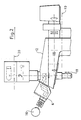
- the microscope stand is designated by the reference symbol (1).
- the reference symbol (2) refers to the transmitted light illumination device and the reference symbol (6) to the eyepiece tube.
- An observer eye is identified by (16).
- the reference number (3) is assigned to the stage and the reference number (4) is assigned to the objective.
- the reference number (5) denotes an incident light illumination device, the illumination beams of which are coaxially reflected into the observation beam path (14) of the axiotron via a splitter plate (13).
- (15) denotes a photometer measuring aperture arranged in an intermediate image plane and (18) an auxiliary light source for illuminating this measuring aperture.
- the reference symbol (17) relates to the pupil plane of a photocathode (7).
- the reference numeral (10) indicates a first interface, which mechanically cuts through the stand (1) and the lens barrel at the designated point in such a way that a lens suitable for measuring and evaluating the natural fluorescence spectra of organic tissue areas can be used.
- a second interface is identified by the reference symbol (20) and is intended to be the approach of a spectrograph or an optical waveguide cross-sectional converter that has a circular shape Convert the visual field into a rectangular one and lead to a spectrograph.
- FIG. 2 shows the fuselage (12) of the axiotron, which remains after the part below the interface (10) and the part above the interface (20) have been separated.
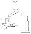
- FIG. 3 shows the attachment of the fuselage (12) to a floor stand (8) which has a freely movable arm and is equipped with a tilting and swiveling device.
- This floor stati is known per se. Instead of a floor stand, a suitable known wall or ceiling stand can also be used.
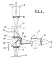
- 19 denotes a light source of known design suitable for recording self-fluorescence spectra. It can be an HBO lamp, for example.
- condenser lenses for imaging the light source (19) in the plane 19 'of the lens (11) are marked.
- the lens (11), as indicated by the double arrow (23), can be moved and focused in the vertical direction. Suitable focusing mechanisms are described, for example, in US Pat. No. 4,342,905 and in the article "Laser Scanning Microscope with Automatic Focusing" in MICROSCOPICA ACTA, Vol. 87, No. 2, March 1983, pages 129-138.
- (24) denotes the object surface which has a remitting and fluorescent surface.
- the illumination beam path (25) denotes a fluorescence excitation filter and (26) a light field diaphragm, which is arranged in an image plane (24 '') of the object (24).
- a color divider 27
- the fluorescent light sent from the object passes through a blocking filter (28) that can be swung in and out in the beam path, and the tube lens (29) through a measuring aperture (30) arranged in the first object image plane (24 ') via a relay lens (31) into the entry slit (32) of a spectrograph (not shown in FIG. 4) or into one Fiber optic cross-section converter, which leads to a spectrograph.
- the entrance slit (32) is arranged in the second image plane (19 ⁇ ) of the light source (19).
- a switchable mirror (33) allows light emitted by the object to enter an observation device in the direction of the arrow (34), for example an eyepiece tube.
Abstract
Description
Die Erfindung betrifft eine Vorrichtung zur Messung und Auswertung von Eigenfluoreszenzspektren organischer Gewebeflächen nach dem Oberbegriff des Patentanspruches 1.The invention relates to a device for measuring and evaluating intrinsic fluorescence spectra of organic tissue areas according to the preamble of
Eine derartige Vorrichtung ist aus der DE 35 42 167 A1 im Zusammenhang mit der nicht vorveröffentlichten Patentanmeldung P 37 18 202.1 bekannt.Such a device is known from DE 35 42 167 A1 in connection with the unpublished patent application P 37 18 202.1.
Die bekannte Vorrichtung verwendet als Lichtquelle die Projektion eines Spaltbildes auf die zu untersuchende organische Gewebefläche.The known device uses the projection of a slit image onto the organic tissue surface to be examined as the light source.
Der vorliegenden Erfindung liegt die Aufgabe zugrunde, für den genannten Zweck eine Vorrichtung anzugeben, die eine flächenhafte Ausleuchtung des Untersuchungsobjektes erlaubt.The present invention is based on the object of specifying a device for the stated purpose which permits areal illumination of the examination object.
Diese Aufgabe wird erfindungsgemaß mit einer Vorrichtung nach den kennzeichnenden Merkmalen des Patentanspruches 1 gelöst. Weitere Ausgestaltungen der Erfindung ergeben sich aus den Merkmalen der Unteransprüche.This object is achieved according to the invention with a device according to the characterizing features of
Die mit der Erfindung erzielten Vorteile bestehen insbesondere darin, daß modulartige Teile eines bekannten Gerätes - eines unter dem Namen Axiotron bekannten Mikroskops - verwendet werden können, wodurch Kosten für eine neue Produktionsserie einsparbar sind. Ein weiterer Vorteil der Erfindung liegt in der koaxial zur Beobachtungsrichtung verlaufenden Beleuchtung des Objekts.The advantages achieved by the invention consist in particular in the fact that modular parts of a known device - a microscope known under the name Axiotron - can be used, whereby costs for a new production series can be saved. Another advantage of the invention lies in the fact that the object is illuminated coaxially with the direction of observation.
Ein Ausführungsbeispiel der Erfindung ist in der Zeichnung dargestellt und wird im folgenden näher beschrieben.An embodiment of the invention is shown in the drawing and will be described in more detail below.
Es zeigen
Figur 1 ein Mikroskop-Photometer bekannter Bauart, das unter dem Namen Axiotron auf dem Markt ist;Figur 2 ein erfindungsgemaß modifiziertes Axiotron im Teilschnitt von der Seite gesehen;- Figur 3 ein an einem Bodenstativ befestigtes modifiziertes Axiotron;
- Figur 4 den optischen Strahlengang in einem erfindungsgemäß modifizierten Axiotron.
- Figure 1 is a microscope photometer of a known type, which is on the market under the name Axiotron;
- Figure 2 is an axiotron modified according to the invention seen in partial section from the side;
- FIG. 3 shows a modified axiotron attached to a floor stand;
- 4 shows the optical beam path in an axiotron modified according to the invention.
In der Darstellung des in Figur 1 gezeigten Axiotron ist mit dem Bezugszeichen (1) das Mikroskopstativ bezeichnet. Auf die Durchlichtbeleuchtungsvorrichtung verweist das Bezugszeichen (2), und auf den Okulartubus das Bezugszeichen (6). Mit (16) ist ein Beobachterauge gekennzeichnet. Dem Objekttisch ist das Bezugszeichen (3) und dem Objektiv das Bezugszeichen (4) zugeordnet. Mit der Kennziffer (5) ist eine Auflichtbeleuchtungsvorrichtung gekennzeichnet, deren Beleuchtungsstrahlen über eine Teilerplatte (13) koaxial in den Beobachtungsstrahlengang (14) des Axiotron eingespiegelt wird. Mit (15) ist eine in einer Zwischenbildebene angeordnete Photometermeßblende bezeichnet und mit (18) eine Hilfslichtquelle zum Beleuchten dieser Meßblende. Das Bezugszeichen (17) bezieht sich auf die Pupillenebene einer Photokathode (7). An dem gezeigten Axiotron ist mit dem Bezugszeichen (10) eine erste Schnittstelle angedeutet, welche das Stativ (1) und den Objektivtubus an der bezeichneten Stelle mechanisch so durchtrennt, daß ein zur Messung und Auswertung von Eigenfluoreszenzspektren organischer Gewebeflächen geeignetes Objektiv eingesetzt werden kann. Eine zweite Schnittstelle ist mit dem Bezugszeichen (20) gekennzeichnet und soll den Ansatz eines Spektrographen oder eines Lichtleiter-Querschnittswandlers, der ein kreisförmiges Gesichtsfeld in ein rechteckiges umwandelt und zu einem Spektrographen fuhrt, ermöglichen.In the illustration of the axiotron shown in FIG. 1, the microscope stand is designated by the reference symbol (1). The reference symbol (2) refers to the transmitted light illumination device and the reference symbol (6) to the eyepiece tube. An observer eye is identified by (16). The reference number (3) is assigned to the stage and the reference number (4) is assigned to the objective. The reference number (5) denotes an incident light illumination device, the illumination beams of which are coaxially reflected into the observation beam path (14) of the axiotron via a splitter plate (13). (15) denotes a photometer measuring aperture arranged in an intermediate image plane and (18) an auxiliary light source for illuminating this measuring aperture. The reference symbol (17) relates to the pupil plane of a photocathode (7). On the axiotron shown, the reference numeral (10) indicates a first interface, which mechanically cuts through the stand (1) and the lens barrel at the designated point in such a way that a lens suitable for measuring and evaluating the natural fluorescence spectra of organic tissue areas can be used. A second interface is identified by the reference symbol (20) and is intended to be the approach of a spectrograph or an optical waveguide cross-sectional converter that has a circular shape Convert the visual field into a rectangular one and lead to a spectrograph.
In der Darstellung der Figur 2 ist der Rumpf (12) des Axiotron gezeigt, der nach Abtrennen des unterhalb der Schnittstelle (10) liegenden Teiles und des oberhalb der Schnittstelle (20) liegenden Teiles verbleibt.The illustration of FIG. 2 shows the fuselage (12) of the axiotron, which remains after the part below the interface (10) and the part above the interface (20) have been separated.
In der Darstellung der Figur 3 ist die Befestigung des Rumpfes (12) an einem Bodenstativ (8) gezeigt, das einen freibeweglichen Arm aufweist und mit einer Kipp- und Schwenkvorrichtung ausgerüstet ist. Dieses Bodenstatiy ist an sich bekannt. Anstelle eines Bodenstatives kann auch ein geeignetes bekanntes Wand- oder Deckenstativ verwendet werden.The illustration in FIG. 3 shows the attachment of the fuselage (12) to a floor stand (8) which has a freely movable arm and is equipped with a tilting and swiveling device. This floor stati is known per se. Instead of a floor stand, a suitable known wall or ceiling stand can also be used.
In der Darstellung der Figur 4 ist mit 19 eine zur Aufnahme von Eigenfluoreszenzspektren geeignete Lichtquelle bekannter Bauart bezeichnet. Es kann sich beispielsweise um eine HBO-Lampe handeln. Mit (21) und (22) sind Kondensorlinsen zur Abbildung der Lichtquelle (19) in die Ebene 19′ des Objektives (11) gekennzeichnet. Das Objektiv (11) ist, wie mit Doppelpfeil (23) angedeutet, in vertikaler Richtung beweglich und fokussierbar. Geeignete Fokussiermechanismen sind beispielsweise in der US-PS 4 342 905 und in dem Aufsatz "Laser-Scanning-Mikroskop mit automatischer Fokussierung" in MICROSCOPICA ACTA, Vol. 87, Nr. 2, March 1983, Seiten 129-138 beschrieben. Mit (24) ist die Objektfläche bezeichnet, die eine remittierende und fluoreszierende Oberfläche aufweist. Im Beleuchtungsstrahlengang ist mit (25) ein Fluoreszenz-Anregungsfilter und mit (26) eine Leuchtfeldblende, die in einer Bildebene (24′′) des Objektes (24) angeordnet ist, bezeichnet. Durch einen Farbteiler (27) gelangt das vom Objekt aus gesandte Fluoreszenzlicht über ein in den Strahlengang ein- und ausschwenkbares Sperrfilter (28) und die Tubuslinse (29) durch eine in der ersten Objektbildebene (24′) angeordnete Meßblende (30) über eine Relaislinse (31) in den Eintrittsspalt (32) eines in der Fig. 4 nicht eingezeichneten Spektrographen oder zu einem Lichtleiter-Querschnittswandler, der zu einem Spektrographen führt. Der Eintrittsspalt (32) ist in der zweiten Bildebene (19˝) der Lichtquelle (19) angeordnet. Über einen schaltbaren Spiegel (33) kann vom Objekt ausgesendetes Licht in eine in Pfeilrichtung (34) liegende Beobachtungsvorrichtung, beispielsweise einen Okulartubus gelangen.In the illustration in FIG. 4, 19 denotes a light source of known design suitable for recording self-fluorescence spectra. It can be an HBO lamp, for example. With (21) and (22) condenser lenses for imaging the light source (19) in the plane 19 'of the lens (11) are marked. The lens (11), as indicated by the double arrow (23), can be moved and focused in the vertical direction. Suitable focusing mechanisms are described, for example, in US Pat. No. 4,342,905 and in the article "Laser Scanning Microscope with Automatic Focusing" in MICROSCOPICA ACTA, Vol. 87, No. 2, March 1983, pages 129-138. (24) denotes the object surface which has a remitting and fluorescent surface. In the illumination beam path, (25) denotes a fluorescence excitation filter and (26) a light field diaphragm, which is arranged in an image plane (24 '') of the object (24). Through a color divider (27), the fluorescent light sent from the object passes through a blocking filter (28) that can be swung in and out in the beam path, and the tube lens (29) through a measuring aperture (30) arranged in the first object image plane (24 ') via a relay lens (31) into the entry slit (32) of a spectrograph (not shown in FIG. 4) or into one Fiber optic cross-section converter, which leads to a spectrograph. The entrance slit (32) is arranged in the second image plane (19˝) of the light source (19). A switchable mirror (33) allows light emitted by the object to enter an observation device in the direction of the arrow (34), for example an eyepiece tube.
Claims (3)
Applications Claiming Priority (2)
| Application Number | Priority Date | Filing Date | Title |
|---|---|---|---|
| DE3815743 | 1988-05-07 | ||
| DE3815743A DE3815743A1 (en) | 1988-05-07 | 1988-05-07 | DEVICE FOR MEASURING AND EVALUATING NATURAL FLUORESCENCE SPECTRES OF ORGANIC TISSUE SURFACES |
Publications (2)
| Publication Number | Publication Date |
|---|---|
| EP0341483A2 true EP0341483A2 (en) | 1989-11-15 |
| EP0341483A3 EP0341483A3 (en) | 1991-03-13 |
Family
ID=6353948
Family Applications (1)
| Application Number | Title | Priority Date | Filing Date |
|---|---|---|---|
| EP19890107440 Ceased EP0341483A3 (en) | 1988-05-07 | 1989-04-25 | Device for measuring and processing spectra of proper fluorescence from surfaces of organic tissues |
Country Status (4)
| Country | Link |
|---|---|
| US (1) | US5014707A (en) |
| EP (1) | EP0341483A3 (en) |
| JP (1) | JPH01313738A (en) |
| DE (1) | DE3815743A1 (en) |
Cited By (1)
| Publication number | Priority date | Publication date | Assignee | Title |
|---|---|---|---|---|
| GB2251701A (en) * | 1990-12-01 | 1992-07-15 | K W Kirk & Sons Limited | UV Microscope illuminator |
Families Citing this family (21)
| Publication number | Priority date | Publication date | Assignee | Title |
|---|---|---|---|---|
| DE4039070A1 (en) * | 1990-12-07 | 1992-06-11 | Philips Patentverwaltung | MULTI-CHANNEL SPECTROMETER |
| DE4217852A1 (en) * | 1992-05-29 | 1993-12-02 | Jenoptik Jena Gmbh | Detecting and analysing cell tissue structure in vivo by light polarisation - using laser source, analyser and difference detector in microscope assembly for distinguishing between healthy and pathological tissue for early tumour diagnosis |
| US5341805A (en) * | 1993-04-06 | 1994-08-30 | Cedars-Sinai Medical Center | Glucose fluorescence monitor and method |
| US5503559A (en) * | 1993-09-30 | 1996-04-02 | Cedars-Sinai Medical Center | Fiber-optic endodontic apparatus and method |
| US5456252A (en) * | 1993-09-30 | 1995-10-10 | Cedars-Sinai Medical Center | Induced fluorescence spectroscopy blood perfusion and pH monitor and method |
| US5701902A (en) * | 1994-09-14 | 1997-12-30 | Cedars-Sinai Medical Center | Spectroscopic burn injury evaluation apparatus and method |
| US5991653A (en) * | 1995-03-14 | 1999-11-23 | Board Of Regents, The University Of Texas System | Near-infrared raman spectroscopy for in vitro and in vivo detection of cervical precancers |
| US5697373A (en) * | 1995-03-14 | 1997-12-16 | Board Of Regents, The University Of Texas System | Optical method and apparatus for the diagnosis of cervical precancers using raman and fluorescence spectroscopies |
| US6258576B1 (en) | 1996-06-19 | 2001-07-10 | Board Of Regents, The University Of Texas System | Diagnostic method and apparatus for cervical squamous intraepithelial lesions in vitro and in vivo using fluorescence spectroscopy |
| US5842995A (en) * | 1996-06-28 | 1998-12-01 | Board Of Regents, The Univerisity Of Texas System | Spectroscopic probe for in vivo measurement of raman signals |
| US6483638B1 (en) * | 1996-07-22 | 2002-11-19 | Kla-Tencor Corporation | Ultra-broadband UV microscope imaging system with wide range zoom capability |
| US20030135122A1 (en) * | 1997-12-12 | 2003-07-17 | Spectrx, Inc. | Multi-modal optical tissue diagnostic system |
| US6217512B1 (en) * | 1997-12-12 | 2001-04-17 | Program For Appropriate Technology In Health | Self-illuminated, non-invasive, visual cervical inspection apparatus and method |
| US6055451A (en) * | 1997-12-12 | 2000-04-25 | Spectrx, Inc. | Apparatus and method for determining tissue characteristics |
| AU6139199A (en) * | 1998-09-11 | 2000-04-03 | Spectrx, Inc. | Multi-modal optical tissue diagnostic system |
| DE19907479A1 (en) * | 1999-02-15 | 2000-08-17 | Univ Schiller Jena | Measurement of different fluorescence spectra on object in case of age-related degeneration of lens with cataract by exciting object region for fluorescence and their confocal imaging on inlet slit of spectrograph |
| US20040147843A1 (en) * | 1999-11-05 | 2004-07-29 | Shabbir Bambot | System and method for determining tissue characteristics |
| US6697666B1 (en) | 1999-06-22 | 2004-02-24 | Board Of Regents, The University Of Texas System | Apparatus for the characterization of tissue of epithelial lined viscus |
| US6563581B1 (en) * | 2000-07-14 | 2003-05-13 | Applera Corporation | Scanning system and method for scanning a plurality of samples |
| SE523138C2 (en) * | 2001-01-11 | 2004-03-30 | Bestwood Ab | Procedure and equipment for illumination and collection of radiation |
| DE102011100507B4 (en) * | 2011-04-29 | 2020-05-14 | Fraunhofer-Gesellschaft zur Förderung der angewandten Forschung e.V. | Portable optical analyzer |
Citations (3)
| Publication number | Priority date | Publication date | Assignee | Title |
|---|---|---|---|---|
| US4500204A (en) * | 1981-04-21 | 1985-02-19 | Agency Of Industrial Science & Technology | Scanning-type lithographic and image-pickup device using optical fiber |
| EP0164680A2 (en) * | 1984-06-05 | 1985-12-18 | Olympus Optical Co., Ltd. | Integrated photometric microscope system |
| DE3718202C1 (en) * | 1987-05-29 | 1988-11-17 | Wolfgang Prof Dr Lohmann | Arrangement for measuring a condition value for organic tissue areas |
Family Cites Families (4)
| Publication number | Priority date | Publication date | Assignee | Title |
|---|---|---|---|---|
| US4342905A (en) * | 1979-08-31 | 1982-08-03 | Nippon Kogaku K.K. | Automatic focusing device of a microscope |
| US4617467A (en) * | 1984-11-16 | 1986-10-14 | Union Oil Company Of California | Apparatus for characterizing kerogens |
| US4758081A (en) * | 1985-07-18 | 1988-07-19 | Bausch & Lomb Incorporated | Control of laser photocoagulation using Raman radiation |
| DE3542167A1 (en) * | 1985-11-29 | 1987-06-04 | Wolfgang Prof Dr Lohmann | METHOD FOR MEASURING THE EYE LENS TURBIDITY AND ARRANGEMENT FOR IMPLEMENTING THE METHOD |
-
1988
- 1988-05-07 DE DE3815743A patent/DE3815743A1/en not_active Withdrawn
-
1989
- 1989-04-25 EP EP19890107440 patent/EP0341483A3/en not_active Ceased
- 1989-05-01 JP JP1109233A patent/JPH01313738A/en active Pending
- 1989-05-08 US US07/348,417 patent/US5014707A/en not_active Expired - Fee Related
Patent Citations (3)
| Publication number | Priority date | Publication date | Assignee | Title |
|---|---|---|---|---|
| US4500204A (en) * | 1981-04-21 | 1985-02-19 | Agency Of Industrial Science & Technology | Scanning-type lithographic and image-pickup device using optical fiber |
| EP0164680A2 (en) * | 1984-06-05 | 1985-12-18 | Olympus Optical Co., Ltd. | Integrated photometric microscope system |
| DE3718202C1 (en) * | 1987-05-29 | 1988-11-17 | Wolfgang Prof Dr Lohmann | Arrangement for measuring a condition value for organic tissue areas |
Non-Patent Citations (3)
| Title |
|---|
| REV. SCI. INSTRUM., Band 57, Nr. 9, September 1986, Seiten 2339-2342; J. MATTIELLO et al.: "Hematoporphyrin-derivative optical-fluorescence-detection instrument for localization of bladder and bronchous carcinoma in situ" * |
| ZEISS INFORMATION, Band 29, Nr. 98, Juli 1987, Seiten 4-8, Oberkochen, DE; G. H\CHERL: "The new generation of microscopes from Carl Zeiss: Research microscopes Axioplan and Axiophot and inspection microscope Axiotron" * |
| ZEISS-INFORM., Band 25, Nr. 90, Juli 1980, Seiten 23-25, Oberkochen, DE; K. BIBER: "OPMI 99 - Ein neues Kleinmikroskop - Programm von Zeiss" * |
Cited By (1)
| Publication number | Priority date | Publication date | Assignee | Title |
|---|---|---|---|---|
| GB2251701A (en) * | 1990-12-01 | 1992-07-15 | K W Kirk & Sons Limited | UV Microscope illuminator |
Also Published As
| Publication number | Publication date |
|---|---|
| US5014707A (en) | 1991-05-14 |
| JPH01313738A (en) | 1989-12-19 |
| EP0341483A3 (en) | 1991-03-13 |
| DE3815743A1 (en) | 1989-11-16 |
Similar Documents
| Publication | Publication Date | Title |
|---|---|---|
| EP0341483A2 (en) | Device for measuring and processing spectra of proper fluorescence from surfaces of organic tissues | |
| DE69737475T2 (en) | COMPATIBLE FLUORESCENCE IMAGING SYSTEM WITH MACRO AND MICROBUTASTOBJECTIVES | |
| DE2852203B2 (en) | Light guide device for an imaging device operated with incident light | |
| WO2003023483A2 (en) | Microscope | |
| EP1664888A1 (en) | Scanning microscope with evanescent wave illumination | |
| WO2005096058A1 (en) | Scanning microscope and method for examining a sample by using scanning microscopy | |
| DE10017823A1 (en) | Microscopic illuminator | |
| DE2944215A1 (en) | LIGHTING DEVICE FOR FLUORESCENCE MICROSCOPE | |
| EP1882970A1 (en) | Laser scanning microscope for fluorescence analysis | |
| DE10120424B4 (en) | Scanning microscope and decoupling element | |
| EP1678545B1 (en) | Microscope with evanescent sample illumination | |
| DE4323129A1 (en) | Microscope with laser illumination - has laser beam input via conventional light inlet and slider with mirror for deflecting light to objective | |
| WO2016012606A1 (en) | Microscope and method for optically examining and/or manipulating a microscopic sample | |
| DE3742806A1 (en) | Method and device for producing fluorescence images | |
| DE4331570A1 (en) | Method and device for optically exciting an energy state in a sample at a sample point with high positional resolution | |
| DE10031458B4 (en) | Scanning microscope with a circulator | |
| DE19618963C5 (en) | Endoscope auxiliary device and method for endoscopic detection of fluorescent light using the same | |
| DE2407270B1 (en) | Comparative microscope | |
| DE102013222562A1 (en) | Microscope for evanescent lighting and punctiform grid illumination | |
| DE102004029733A1 (en) | Scanning microscope and scanning microscopy method | |
| DE3744156A1 (en) | Inverse microscope for transmitted illumination (transillumination) | |
| DE102016114115A1 (en) | Fluorescence microscope | |
| DE4345538C2 (en) | fluorescence microscope | |
| DE102005023768B4 (en) | Method for determining the orientation of molecules in biological samples | |
| DE102017124547B4 (en) | microscope |
Legal Events
| Date | Code | Title | Description |
|---|---|---|---|
| PUAI | Public reference made under article 153(3) epc to a published international application that has entered the european phase |
Free format text: ORIGINAL CODE: 0009012 |
|
| AK | Designated contracting states |
Kind code of ref document: A2 Designated state(s): AT CH FR GB IT LI NL SE |
|
| PUAL | Search report despatched |
Free format text: ORIGINAL CODE: 0009013 |
|
| AK | Designated contracting states |
Kind code of ref document: A3 Designated state(s): AT CH FR GB IT LI NL SE |
|
| 17P | Request for examination filed |
Effective date: 19910820 |
|
| 17Q | First examination report despatched |
Effective date: 19930330 |
|
| STAA | Information on the status of an ep patent application or granted ep patent |
Free format text: STATUS: THE APPLICATION HAS BEEN REFUSED |
|
| 18R | Application refused |
Effective date: 19930923 |