EP0341093A2 - Identifying gemstones - Google Patents
Identifying gemstones Download PDFInfo
- Publication number
- EP0341093A2 EP0341093A2 EP89304636A EP89304636A EP0341093A2 EP 0341093 A2 EP0341093 A2 EP 0341093A2 EP 89304636 A EP89304636 A EP 89304636A EP 89304636 A EP89304636 A EP 89304636A EP 0341093 A2 EP0341093 A2 EP 0341093A2
- Authority
- EP
- European Patent Office
- Prior art keywords
- radiation
- modulated
- frequency
- raman
- gemstones
- Prior art date
- Legal status (The legal status is an assumption and is not a legal conclusion. Google has not performed a legal analysis and makes no representation as to the accuracy of the status listed.)
- Withdrawn
Links
- 239000010437 gem Substances 0.000 title claims description 19
- 229910001751 gemstone Inorganic materials 0.000 title claims description 19
- 230000005855 radiation Effects 0.000 claims abstract description 65
- 238000001069 Raman spectroscopy Methods 0.000 claims abstract description 33
- 239000010432 diamond Substances 0.000 claims abstract description 32
- 239000002245 particle Substances 0.000 claims abstract description 23
- 229910003460 diamond Inorganic materials 0.000 claims abstract description 18
- 238000000034 method Methods 0.000 claims abstract description 16
- 238000001914 filtration Methods 0.000 claims abstract description 5
- 230000001678 irradiating effect Effects 0.000 claims description 4
- 238000004020 luminiscence type Methods 0.000 abstract description 20
- 239000000463 material Substances 0.000 description 8
- 238000001514 detection method Methods 0.000 description 7
- 230000003287 optical effect Effects 0.000 description 5
- 238000010586 diagram Methods 0.000 description 2
- 229910021532 Calcite Inorganic materials 0.000 description 1
- 241000579895 Chlorostilbon Species 0.000 description 1
- 230000003213 activating effect Effects 0.000 description 1
- XKRFYHLGVUSROY-UHFFFAOYSA-N argon Substances [Ar] XKRFYHLGVUSROY-UHFFFAOYSA-N 0.000 description 1
- 229910052786 argon Inorganic materials 0.000 description 1
- 230000000903 blocking effect Effects 0.000 description 1
- 238000011109 contamination Methods 0.000 description 1
- CPBQJMYROZQQJC-UHFFFAOYSA-N helium neon Chemical compound [He].[Ne] CPBQJMYROZQQJC-UHFFFAOYSA-N 0.000 description 1
- 229910052500 inorganic mineral Inorganic materials 0.000 description 1
- 238000007689 inspection Methods 0.000 description 1
- 239000007788 liquid Substances 0.000 description 1
- 239000011707 mineral Substances 0.000 description 1
- 238000012986 modification Methods 0.000 description 1
- 230000004048 modification Effects 0.000 description 1
- 230000035945 sensitivity Effects 0.000 description 1
- 229910052596 spinel Inorganic materials 0.000 description 1
- 239000011029 spinel Substances 0.000 description 1
- 238000004875 x-ray luminescence Methods 0.000 description 1
- 229910052845 zircon Inorganic materials 0.000 description 1
Images


Classifications
-
- B—PERFORMING OPERATIONS; TRANSPORTING
- B07—SEPARATING SOLIDS FROM SOLIDS; SORTING
- B07C—POSTAL SORTING; SORTING INDIVIDUAL ARTICLES, OR BULK MATERIAL FIT TO BE SORTED PIECE-MEAL, e.g. BY PICKING
- B07C5/00—Sorting according to a characteristic or feature of the articles or material being sorted, e.g. by control effected by devices which detect or measure such characteristic or feature; Sorting by manually actuated devices, e.g. switches
- B07C5/36—Sorting apparatus characterised by the means used for distribution
- B07C5/363—Sorting apparatus characterised by the means used for distribution by means of air
- B07C5/365—Sorting apparatus characterised by the means used for distribution by means of air using a single separation means
- B07C5/366—Sorting apparatus characterised by the means used for distribution by means of air using a single separation means during free fall of the articles
-
- B—PERFORMING OPERATIONS; TRANSPORTING
- B07—SEPARATING SOLIDS FROM SOLIDS; SORTING
- B07C—POSTAL SORTING; SORTING INDIVIDUAL ARTICLES, OR BULK MATERIAL FIT TO BE SORTED PIECE-MEAL, e.g. BY PICKING
- B07C5/00—Sorting according to a characteristic or feature of the articles or material being sorted, e.g. by control effected by devices which detect or measure such characteristic or feature; Sorting by manually actuated devices, e.g. switches
- B07C5/34—Sorting according to other particular properties
- B07C5/342—Sorting according to other particular properties according to optical properties, e.g. colour
- B07C5/3425—Sorting according to other particular properties according to optical properties, e.g. colour of granular material, e.g. ore particles, grain
- B07C5/3427—Sorting according to other particular properties according to optical properties, e.g. colour of granular material, e.g. ore particles, grain by changing or intensifying the optical properties prior to scanning, e.g. by inducing fluorescence under UV or x-radiation, subjecting the material to a chemical reaction
-
- G—PHYSICS
- G01—MEASURING; TESTING
- G01N—INVESTIGATING OR ANALYSING MATERIALS BY DETERMINING THEIR CHEMICAL OR PHYSICAL PROPERTIES
- G01N21/00—Investigating or analysing materials by the use of optical means, i.e. using sub-millimetre waves, infrared, visible or ultraviolet light
- G01N21/62—Systems in which the material investigated is excited whereby it emits light or causes a change in wavelength of the incident light
- G01N21/63—Systems in which the material investigated is excited whereby it emits light or causes a change in wavelength of the incident light optically excited
- G01N21/64—Fluorescence; Phosphorescence
- G01N21/6489—Photoluminescence of semiconductors
-
- G—PHYSICS
- G01—MEASURING; TESTING
- G01N—INVESTIGATING OR ANALYSING MATERIALS BY DETERMINING THEIR CHEMICAL OR PHYSICAL PROPERTIES
- G01N21/00—Investigating or analysing materials by the use of optical means, i.e. using sub-millimetre waves, infrared, visible or ultraviolet light
- G01N21/62—Systems in which the material investigated is excited whereby it emits light or causes a change in wavelength of the incident light
- G01N21/63—Systems in which the material investigated is excited whereby it emits light or causes a change in wavelength of the incident light optically excited
- G01N21/65—Raman scattering
-
- G—PHYSICS
- G01—MEASURING; TESTING
- G01N—INVESTIGATING OR ANALYSING MATERIALS BY DETERMINING THEIR CHEMICAL OR PHYSICAL PROPERTIES
- G01N21/00—Investigating or analysing materials by the use of optical means, i.e. using sub-millimetre waves, infrared, visible or ultraviolet light
- G01N21/84—Systems specially adapted for particular applications
- G01N21/87—Investigating jewels
-
- G—PHYSICS
- G01—MEASURING; TESTING
- G01N—INVESTIGATING OR ANALYSING MATERIALS BY DETERMINING THEIR CHEMICAL OR PHYSICAL PROPERTIES
- G01N21/00—Investigating or analysing materials by the use of optical means, i.e. using sub-millimetre waves, infrared, visible or ultraviolet light
- G01N21/17—Systems in which incident light is modified in accordance with the properties of the material investigated
- G01N2021/1734—Sequential different kinds of measurements; Combining two or more methods
-
- G—PHYSICS
- G01—MEASURING; TESTING
- G01N—INVESTIGATING OR ANALYSING MATERIALS BY DETERMINING THEIR CHEMICAL OR PHYSICAL PROPERTIES
- G01N21/00—Investigating or analysing materials by the use of optical means, i.e. using sub-millimetre waves, infrared, visible or ultraviolet light
- G01N21/17—Systems in which incident light is modified in accordance with the properties of the material investigated
- G01N2021/1789—Time resolved
-
- G—PHYSICS
- G01—MEASURING; TESTING
- G01N—INVESTIGATING OR ANALYSING MATERIALS BY DETERMINING THEIR CHEMICAL OR PHYSICAL PROPERTIES
- G01N21/00—Investigating or analysing materials by the use of optical means, i.e. using sub-millimetre waves, infrared, visible or ultraviolet light
- G01N21/84—Systems specially adapted for particular applications
- G01N2021/845—Objects on a conveyor
-
- G—PHYSICS
- G01—MEASURING; TESTING
- G01N—INVESTIGATING OR ANALYSING MATERIALS BY DETERMINING THEIR CHEMICAL OR PHYSICAL PROPERTIES
- G01N21/00—Investigating or analysing materials by the use of optical means, i.e. using sub-millimetre waves, infrared, visible or ultraviolet light
- G01N21/84—Systems specially adapted for particular applications
- G01N21/86—Investigating moving sheets
- G01N2021/8609—Optical head specially adapted
- G01N2021/8627—Optical head specially adapted with an illuminator over the whole width
- G01N2021/8636—Detecting arrangement therefore, e.g. collimators, screens
-
- G—PHYSICS
- G01—MEASURING; TESTING
- G01N—INVESTIGATING OR ANALYSING MATERIALS BY DETERMINING THEIR CHEMICAL OR PHYSICAL PROPERTIES
- G01N21/00—Investigating or analysing materials by the use of optical means, i.e. using sub-millimetre waves, infrared, visible or ultraviolet light
- G01N21/84—Systems specially adapted for particular applications
- G01N21/85—Investigating moving fluids or granular solids
-
- G—PHYSICS
- G01—MEASURING; TESTING
- G01N—INVESTIGATING OR ANALYSING MATERIALS BY DETERMINING THEIR CHEMICAL OR PHYSICAL PROPERTIES
- G01N2201/00—Features of devices classified in G01N21/00
- G01N2201/06—Illumination; Optics
- G01N2201/069—Supply of sources
- G01N2201/0696—Pulsed
- G01N2201/0697—Pulsed lasers
Definitions
- the present invention relates to a method of, and apparatus for, identifying gemstones, in which incident or exciting radiation is projected onto the particle in question, the emitted radiation is detected, and the gemstone is identified according to the radiation emitted.
- the method can be used to examine single particles or a number of particles along an extended line.
- the invention was developed for sorting gemstones, and specifically diamonds, from gemstone-bearing ore, to separate the diamonds from gangues (host material). It is desirable to be able to identify gemstones among gangue particles which are moving in wide path, normally on a conveyor belt but possibly whilst dropping or in flight from the end of a conveyor belt or in another means of conveyance such as a liquid carrier.
- the width of the path can be any suitable width, for instance 300 mm or 1 or 2 meters; in general, the width of the path should be capable of accommodating a number of the particles.
- the invention can be used as a general technique for examining and can be applied to identifying any suitable discrete objects or to general inspection techniques.
- the remainder of the description is particularly concerned with using the Raman emission, but the invention is equally applicable to detecting other emitted radiation, such as X-ray luminescence, or radiation or luminescence exited by visible, infra-red or ultra-violet radiation.
- emitted radiation such as X-ray luminescence, or radiation or luminescence exited by visible, infra-red or ultra-violet radiation.
- the exciting radiation not only causes the diamond Raman emissions, but also excites other luminescences.
- the gangue does not exhibit Raman emission with a frequency shift characteristics of diamond.
- gangue, and some diamonds emit other wavelength radiation or fluorescence, and this gives considerable problems in identifying only Raman radiation and hence the diamonds.
- the Raman emission is very weak, and can be completely swamped by the other emitted radiations.
- the present invention provides methods as set forth in Claims 1, 2 or 13 and apparatus as set forth in Claims 7, 8 or 14.
- the remaining Claims set forth preferred or optional features of the invention.
- the invention provides better discrimination from competing luminescence (e.g. to sort diamonds from zircons) and background luminescence. There is no need for e.g. beam splitters to detect and subtract the background luminescence. It may also be possible to have larger apertures or larger pass bands in the viewing system, and hence greater radiation capture.
- the Raman radiation is distinguished from the other emitted radiations by the very fast rise and decay times, or life times of Raman emissions - the rise and decay times are roughly the same, and are about 3 ps, though at this speed the times are substantially affected by the transit time through the diamond itself and hence by the size of the diamond; the luminescence rise and decay times, or life times, for diamonds and certain minerals which one expects to find in diamond-bearing gangue ar generally between 3 ns and 10 ms.
- the invention can be used to detect emitted radiations having life times from 3ps to 100 msec, say, depending on the type of sort being carried out and the radiation to be detected; luminescence lifetimes will in general be of the order of nanoseconds up to of the order of tens of nanoseconds.
- any luminescence can be detected which has a rise, decay or life time shorter than that luminescence emitted by competing material and which would pass through any filtering used; it should be noted in this context that e.g. when sorting diamonds from gangue, it is acceptable if some lumps of gangue are also sorted out with the diamonds.
- the exciting irradiation can be modulated at a frequency of say 10 MHz to 1 GHz.
- the radiation emitted by the object or zone being examined will try and follow the modulated exciting irradiation and is detected e.g. with a detetor having a rise time response of say about 0.2 ns.
- the invention exploits the very short life time of say the Raman signal compared to the relatively long life times of other luminescence processes; a good signal would be obtained from the Raman emission and lower signals from the other luminescence as the other luminescence would not be fully active due to its relatively long rise time constants.
- the exciting irradiation is modulated such that the time interval of the modulation is short compared to the rise or decay time of the luminescence emission.
- a detection system and associated electronics can process the signals and select and eject material according to luminescent rise/decay time or life time criteria.
- the detector should provide a signal which is modulated at a frequency corresponding to the incident radiation frequency; to do this, the detector itself could in theory be switched on and off or made effective and ineffective, or its output signal could be chopped, at a frequency normally equal to the incident radiation frequency (though e.g. a multiple of the pulse frequency is in theory possible).
- the detector In practice, it is preferred to keep the detector on and determine whether it is giving a signal containing a modulation burst at the incident radiation frequency; the modulation burst is following the e.g. Raman emission.
- the modulation burst is following the e.g. Raman emission.
- the Raman emission In efffect, by using phase sensitive and other detection techniques, it is possible to detect the Raman emission as the AC component of the signal.
- the background fluorescence will be the DC component of the detected signal.
- narrow band pass filtering may be required as other materials present may also have luminescence of a similar life time, but at a different wave length. However, in general, much more of the emitted radiation can be collected using the invention.
- a wide aperture viewing system can be arranged so that the angle of incidence on the narrow band pass filter means is within acceptable limits. Such a viewing system is described in our Patent Application No. EP 89 304 642.
- the exciting radiation can be modulated by pulsing (chopping), e.g. sinusoidal or triangular. This may be achieved by using an external modulator or a mode-locked laser.
- the exciting radiation can have any suitable form.
- a multiple sort could for instance be for diamonds, emeralds and rubies.
- the objects or zones can be sequentially irradiated and/or detected.
- the intensity of the anti-Stokes signal is, at room temperature, calculated as being approximately one three-hundredths of the intensity of the Stokes signal. This made the anti-Stokes Raman signal very unattractive, particularly having regard to the fact that the Stokes signal itself is very weak; it is difficult to capture sufficient Raman radiation for examination of an object.
- the use of the anti-Stokes signal can be advantageous in the particular cases of identifying diamonds, or of examining gangue for picking out diamonds.
- the background competing luminescence from the diamond itself may be significantly reduced on the shorter wave-length (higher energy) side of the incident radiation wave-length, resulting in an improved Raman signal to background ratio.
- the wave-lengths detected there is less broad band luminescence from the diamond itself.
- the lessened contamination enables one to use slightly wider band width optical filters in an optical detection system, for instance reducing the necessity to avoid off-axis incident radiation.
- detection instruments such as photo-multiplier photocathodes, have enhanced sensitivity at shorter wave-lengths.
- the material being sorted can be heated, which increases the relative strength of the anti-Stokes signal. It would be possible to look at both Raman signals simultaneously, and in this way obtain additional discrimination.
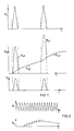
- Figure 1 shows three schematic graphs against time, R i being the incident, exciting irradiation, R e being the emitted radiation and D being the detection.
- R e1 is the Raman emission and R e2 is fluorescence.
- the exciting radiation is pulsed als in the R i /t graph and the detector is activated, or its output signal is chopped, as in the D/t graph. It will be seen that the detector is effective when the Raman emission R e1 is near its maximum and the other luminescent radiation R e2 has not risen so far as to interfere with the detection of the Raman emission R ei , i.e. the detector does not effectively detect emitted radiation which has a substantially longer rise time than the Raman emission R e1 . By keeping the pulse length short relative to the pulse frequency, the intensity of the other luminescence remains low and the Raman emission is either of greater intensity than the other luminescence, or at least of sufficient intensity to be detectable.
- Figure 2 shows, on a much longer time scale t , the exciting radiation R1 and the emitted radiation R e when a diamond is detected, i.e. when the scan passes over a diamond.
- the detector signal will be similar to that of the emitted radiation.
- the modulation burst indicates Raman emission and hence the presence of the diamond.
- the Raman emission can be distinguished by suitable thresholding which removes the background signal caused by other luminescence, or can be distinguished by heterodyne detection or any suitable demodulation electronics.
- FIG 3 shows a simple practical arrangement, in which a V-belt 1 is used as a single particle feeder (a similar single particle feeder such as a pick-up wheel may be used).
- the objects or particles 2 are fed onto the belt 1 in any suitable way, and at the end of the belt pass through a beam projected by a laser 3 with an optical laser beam modulator 4.
- the modulator 4 modulates the beam in a generally sinusoidal manner.
- the particles 2 are examined by an optical collection system 5 and a detector 6 in the form of a photo-multiplier tube (PMT).
- PMT photo-multiplier tube
- Suitable filters are incorporated, a laser wavelength blocking filter 7 and a narrow band pass filter 8 being shown.
- suitable ejection means shown as an air jet 9.
- Reject particles 2 (which would be the vast majority in the case of gangue sorting) do not cause the air jet 9 to be operated and pass into a reject bin 10.
- Selected particles cause the air jet 9 to be operated and are blown out of their normal trajectory into a sort bin 11.
- the laser wavelength is 514.5 nm, modulated at a frequency of 1 GHz.
- 552.4 nm Raman emission (the diamond Stokes emission) can be observed using a 1 nm wide band pass for the filter 8, provided the background is subtracted by ratioing the backgrounds at 537 and 567 nm generally as described in said Patent Application.
- a 5 nm band can be used for the pass filter 8, with no background subtraction. It is believed possible, and may be preferable, to observe the 481.5 nm anti-Stokes emission, in a similar manner.
- the modulator 4 can be a Bragg cell, or the laser 3 and modulator 4 can be replaceld by a mode-locked laser.
- the PMT 6 can be a microchannel plate PMT, which has a very fast time.
- Another embodiment uses a helium-neon laser operating at 632.8 nm, its principal Raman emissions for diamond consist of two sharp lines at 691.1 nm (Stokes) and 583.6 nm (anti-Stokes).
- the electronic circuitry includes a demodulator drive 12 for the beam modulator 4, an amplifier/power supply unit 13, a demodulator 14 for the signal from the PMT 6, and a microprocessor 15 with the necessary logic for identifying the Raman emissions from e.g. diamonds and activating the jet 9.
- the beam from the laser 3 is scanned across a wide belt 21 using a suitable scanning system 22 (e.g. a galvonometer or rotating polygon).
- a suitable scanning system 22 e.g. a galvonometer or rotating polygon.
- a suitable light collecting system 23 is used.
- the system 23 has a wide aperture and a narrow band pass filter with the optics arranged so that the angle of incidence on the filter is within acceptable limits.
- Such optical systems are described in general terms in said Patent Application, and Figures 2 to 7 of said Patent Application disclose one suitable system.
Abstract
Description
- The present invention relates to a method of, and apparatus for, identifying gemstones, in which incident or exciting radiation is projected onto the particle in question, the emitted radiation is detected, and the gemstone is identified according to the radiation emitted. The method can be used to examine single particles or a number of particles along an extended line.
- The invention was developed for sorting gemstones, and specifically diamonds, from gemstone-bearing ore, to separate the diamonds from gangues (host material). It is desirable to be able to identify gemstones among gangue particles which are moving in wide path, normally on a conveyor belt but possibly whilst dropping or in flight from the end of a conveyor belt or in another means of conveyance such as a liquid carrier. The width of the path can be any suitable width, for instance 300 mm or 1 or 2 meters; in general, the width of the path should be capable of accommodating a number of the particles. However, the invention can be used as a general technique for examining and can be applied to identifying any suitable discrete objects or to general inspection techniques.
- The remainder of the description is particularly concerned with using the Raman emission, but the invention is equally applicable to detecting other emitted radiation, such as X-ray luminescence, or radiation or luminescence exited by visible, infra-red or ultra-violet radiation.
- It is known that when certain materials are irradiated, in addition to scattering the incident radiation, they emit radiation in bands of frequencies different from the exiting radiation - this is called the Raman shift. The frequency bands (called Stokes and anti-Stokes) are different from and equally spaced on either side of the frequency of the exciting radiation; the frequency differences are uniquely characteristic of a material. These emissions enable diamond to be identified and sorted from other materials such as spinel, calcite and zirccons. Although there are two Raman frequencies, one normally looks at the lower frequency (longer wavelength) Stokes emission as it has the greater intensity under normal operating conditions.
- The possibility of using the Raman shift to sort or identify diamonds has been described in general terms in for instance GB-A-2 140 555, GB-A-2 199 657, WO 86/07457 and WO 88/01378.
- Normally, the exciting radiation not only causes the diamond Raman emissions, but also excites other luminescences. The gangue does not exhibit Raman emission with a frequency shift characteristics of diamond. However gangue, and some diamonds, emit other wavelength radiation or fluorescence, and this gives considerable problems in identifying only Raman radiation and hence the diamonds. The Raman emission is very weak, and can be completely swamped by the other emitted radiations.
- The present invention provides methods as set forth in
Claims Claims 7, 8 or 14. The remaining Claims set forth preferred or optional features of the invention. - The invention provides better discrimination from competing luminescence (e.g. to sort diamonds from zircons) and background luminescence. There is no need for e.g. beam splitters to detect and subtract the background luminescence. It may also be possible to have larger apertures or larger pass bands in the viewing system, and hence greater radiation capture.
- Using the invention, the Raman radiation is distinguished from the other emitted radiations by the very fast rise and decay times, or life times of Raman emissions - the rise and decay times are roughly the same, and are about 3 ps, though at this speed the times are substantially affected by the transit time through the diamond itself and hence by the size of the diamond; the luminescence rise and decay times, or life times, for diamonds and certain minerals which one expects to find in diamond-bearing gangue ar generally between 3 ns and 10 ms. Although not limited to such values, the invention can be used to detect emitted radiations having life times from 3ps to 100 msec, say, depending on the type of sort being carried out and the radiation to be detected; luminescence lifetimes will in general be of the order of nanoseconds up to of the order of tens of nanoseconds. For diamond and other objects and zones, any luminescence can be detected which has a rise, decay or life time shorter than that luminescence emitted by competing material and which would pass through any filtering used; it should be noted in this context that e.g. when sorting diamonds from gangue, it is acceptable if some lumps of gangue are also sorted out with the diamonds.
- The use of delay times in examining samples has been disclosed in US 4 632 550, US 4 786 170, an article by Van Duyne et al in "Analytical Chemistry", Vol. 46, No. 2, pp 213-222, an article by Everall et al in "Journal of Raman Spectroscopy", Vol. 17, pp 414-423, an article by Watanabe et al in "Review of Scientific Instrument", 56 (6), pp 1195-1198, and an article by Howard et al in "Journal of Physical and Scientific Instruments", 19, pp 934-943.
- In practice, the exciting irradiation can be modulated at a frequency of say 10 MHz to 1 GHz. The radiation emitted by the object or zone being examined will try and follow the modulated exciting irradiation and is detected e.g. with a detetor having a rise time response of say about 0.2 ns. Thus the invention exploits the very short life time of say the Raman signal compared to the relatively long life times of other luminescence processes; a good signal would be obtained from the Raman emission and lower signals from the other luminescence as the other luminescence would not be fully active due to its relatively long rise time constants. In a preferred system, the exciting irradiation is modulated such that the time interval of the modulation is short compared to the rise or decay time of the luminescence emission. A detection system and associated electronics can process the signals and select and eject material according to luminescent rise/decay time or life time criteria. In a general sense, the detector should provide a signal which is modulated at a frequency corresponding to the incident radiation frequency; to do this, the detector itself could in theory be switched on and off or made effective and ineffective, or its output signal could be chopped, at a frequency normally equal to the incident radiation frequency (though e.g. a multiple of the pulse frequency is in theory possible). In practice, it is preferred to keep the detector on and determine whether it is giving a signal containing a modulation burst at the incident radiation frequency; the modulation burst is following the e.g. Raman emission. In efffect, by using phase sensitive and other detection techniques, it is possible to detect the Raman emission as the AC component of the signal. The background fluorescence will be the DC component of the detected signal.
- Some form of narrow band pass filtering may be required as other materials present may also have luminescence of a similar life time, but at a different wave length. However, in general, much more of the emitted radiation can be collected using the invention. A wide aperture viewing system can be arranged so that the angle of incidence on the narrow band pass filter means is within acceptable limits. Such a viewing system is described in our Patent Application No. EP 89 304 642.
- The exciting radiation can be modulated by pulsing (chopping), e.g. sinusoidal or triangular. This may be achieved by using an external modulator or a mode-locked laser. In general, the exciting radiation can have any suitable form.
- It is possible to operate with more than one modulation frequency and/or laser wavelength to perform multiple sorting (or object or zone identification) or alternatively strengthened discrimination, on the basis or different decay or life time modes; a multiple sort could for instance be for diamonds, emeralds and rubies. This could be done with a single source of exciting radiation, or with more than one source irradiating the same location, and employing beam splitting to detect the different frequencies - the exciting radiation can contain different wavelengths, e.g. by projecting with two different lasers. Alternatively, the objects or zones can be sequentially irradiated and/or detected.
- The intensity of the anti-Stokes signal is, at room temperature, calculated as being approximately one three-hundredths of the intensity of the Stokes signal. This made the anti-Stokes Raman signal very unattractive, particularly having regard to the fact that the Stokes signal itself is very weak; it is difficult to capture sufficient Raman radiation for examination of an object.
- However, it has been found that the use of the anti-Stokes signal can be advantageous in the particular cases of identifying diamonds, or of examining gangue for picking out diamonds. The background competing luminescence from the diamond itself may be significantly reduced on the shorter wave-length (higher energy) side of the incident radiation wave-length, resulting in an improved Raman signal to background ratio. In other words, at the wave-lengths detected, there is less broad band luminescence from the diamond itself. The lessened contamination enables one to use slightly wider band width optical filters in an optical detection system, for instance reducing the necessity to avoid off-axis incident radiation. Furthermore, detection instruments, such as photo-multiplier photocathodes, have enhanced sensitivity at shorter wave-lengths.
- The material being sorted can be heated, which increases the relative strength of the anti-Stokes signal. It would be possible to look at both Raman signals simultaneously, and in this way obtain additional discrimination.
- The invention will be further described, by way of example, with reference to the accompanying drawings, in which:-
- Figure 1 is a schematic diagram illustrating the principle of the invention;
- Figure 2 is a schematic diagram illustrating the principle of operation of one embodiment of the invention;
- Figure 3 illustrates a first embodiment of the invention; and
- Figure 4 illustrates a second embodiment of the invention.
- Figure 1 shows three schematic graphs against time, Ri being the incident, exciting irradiation, Re being the emitted radiation and D being the detection. In the Re/t graph, Re1 is the Raman emission and Re2 is fluorescence.
- The exciting radiation is pulsed als in the Ri/t graph and the detector is activated, or its output signal is chopped, as in the D/t graph. It will be seen that the detector is effective when the Raman emission Re1 is near its maximum and the other luminescent radiation Re2 has not risen so far as to interfere with the detection of the Raman emission Rei, i.e. the detector does not effectively detect emitted radiation which has a substantially longer rise time than the Raman emission Re1. By keeping the pulse length short relative to the pulse frequency, the intensity of the other luminescence remains low and the Raman emission is either of greater intensity than the other luminescence, or at least of sufficient intensity to be detectable.
- Figure 2 shows, on a much longer time scale t, the exciting radiation R₁ and the emitted radiation Re when a diamond is detected, i.e. when the scan passes over a diamond. The detector signal will be similar to that of the emitted radiation. The modulation burst indicates Raman emission and hence the presence of the diamond. The Raman emission can be distinguished by suitable thresholding which removes the background signal caused by other luminescence, or can be distinguished by heterodyne detection or any suitable demodulation electronics.
- Figure 3 shows a simple practical arrangement, in which a V-belt 1 is used as a single particle feeder (a similar single particle feeder such as a pick-up wheel may be used). The objects or
particles 2 are fed onto the belt 1 in any suitable way, and at the end of the belt pass through a beam projected by alaser 3 with an opticallaser beam modulator 4. Themodulator 4 modulates the beam in a generally sinusoidal manner. At the point where the beam strikes theparticles 2, theparticles 2 are examined by anoptical collection system 5 and adetector 6 in the form of a photo-multiplier tube (PMT). Suitable filters are incorporated, a laser wavelength blocking filter 7 and a narrow band pass filter 8 being shown. As theparticles 2 are projected off the end of the belt 1, they pass suitable ejection means, shown as anair jet 9. Reject particles 2 (which would be the vast majority in the case of gangue sorting) do not cause theair jet 9 to be operated and pass into areject bin 10. Selected particles cause theair jet 9 to be operated and are blown out of their normal trajectory into asort bin 11. - In one embodiment using a 2 watt
argon ion laser 3, the laser wavelength is 514.5 nm, modulated at a frequency of 1 GHz. 552.4 nm Raman emission (the diamond Stokes emission) can be observed using a 1 nm wide band pass for the filter 8, provided the background is subtracted by ratioing the backgrounds at 537 and 567 nm generally as described in said Patent Application. Alternatively, a 5 nm band can be used for the pass filter 8, with no background subtraction. It is believed possible, and may be preferable, to observe the 481.5 nm anti-Stokes emission, in a similar manner. Themodulator 4 can be a Bragg cell, or thelaser 3 andmodulator 4 can be replaceld by a mode-locked laser. ThePMT 6 can be a microchannel plate PMT, which has a very fast time. - Another embodiment uses a helium-neon laser operating at 632.8 nm, its principal Raman emissions for diamond consist of two sharp lines at 691.1 nm (Stokes) and 583.6 nm (anti-Stokes).
- The electronic circuitry includes a
demodulator drive 12 for thebeam modulator 4, an amplifier/power supply unit 13, ademodulator 14 for the signal from thePMT 6, and amicroprocessor 15 with the necessary logic for identifying the Raman emissions from e.g. diamonds and activating thejet 9. - In Figure 4, the beam from the
laser 3 is scanned across awide belt 21 using a suitable scanning system 22 (e.g. a galvonometer or rotating polygon). In this way, the laser beam is scanned across thebelt 21 just before theparticles 2 are projected off the belt. A suitablelight collecting system 23 is used. Thesystem 23 has a wide aperture and a narrow band pass filter with the optics arranged so that the angle of incidence on the filter is within acceptable limits. Such optical systems are described in general terms in said Patent Application, and Figures 2 to 7 of said Patent Application disclose one suitable system. - Any thing discussed in said Patent Application can be incorporated in the present invention, provided it is suitable. Said Patent Application gives many details which are applicable to the present invention.
- The present invention has been described above purely by way of example, and modifications can be made within the spirit of the invention.
Claims (16)
irradiating a line across the path with modulated radiation so as to cause an emission from gemstones to be identified of radiation having a short rise and/or decay time; and
detecting emitted radiation which is modulated at a frequency corresponding to the frequency of modulation of the exciting radiation.
Applications Claiming Priority (8)
| Application Number | Priority Date | Filing Date | Title |
|---|---|---|---|
| GB888810723A GB8810723D0 (en) | 1988-05-06 | 1988-05-06 | Identifying specific objects/zones |
| GB8810723 | 1988-05-06 | ||
| GB8816167 | 1988-07-07 | ||
| GB888816167A GB8816167D0 (en) | 1988-07-07 | 1988-07-07 | Identifying objects/zones |
| GB888826225A GB8826225D0 (en) | 1988-11-09 | 1988-11-09 | Examining object |
| GB8826225 | 1988-11-09 | ||
| GB8906853 | 1989-03-23 | ||
| GB898906853A GB8906853D0 (en) | 1989-03-23 | 1989-03-23 | Examining an article or objects |
Publications (2)
| Publication Number | Publication Date |
|---|---|
| EP0341093A2 true EP0341093A2 (en) | 1989-11-08 |
| EP0341093A3 EP0341093A3 (en) | 1991-02-27 |
Family
ID=27450094
Family Applications (1)
| Application Number | Title | Priority Date | Filing Date |
|---|---|---|---|
| EP19890304636 Withdrawn EP0341093A3 (en) | 1988-05-06 | 1989-05-08 | Identifying gemstones |
Country Status (7)
| Country | Link |
|---|---|
| EP (1) | EP0341093A3 (en) |
| JP (1) | JPH0285749A (en) |
| AU (1) | AU630351B2 (en) |
| BR (1) | BR8902133A (en) |
| DE (1) | DE341093T1 (en) |
| GB (1) | GB2219080B (en) |
| IN (1) | IN174123B (en) |
Cited By (6)
| Publication number | Priority date | Publication date | Assignee | Title |
|---|---|---|---|---|
| EP0341095A2 (en) * | 1988-05-06 | 1989-11-08 | Gersan Establishment | Identifying the position of objects or zones |
| EP0552819A2 (en) * | 1988-05-06 | 1993-07-28 | Gersan Establishment | Sorting diamonds or other minerals |
| WO2005061400A1 (en) * | 2003-12-12 | 2005-07-07 | Element Six Limited | Method of incorporating a mark in cvd diamond |
| WO2017001835A1 (en) * | 2015-06-30 | 2017-01-05 | De Beers Uk Ltd | Luminescence measurements in diamond |
| CN110064593A (en) * | 2019-04-30 | 2019-07-30 | 宋宏亮 | A kind of gangue solids waste resource recycling and reusing processing unit |
| US11435296B2 (en) * | 2019-05-22 | 2022-09-06 | Ditech—Diamond Inspection Technologies Ltd. | Method and system for grading gemstones |
Families Citing this family (3)
| Publication number | Priority date | Publication date | Assignee | Title |
|---|---|---|---|---|
| GB9103552D0 (en) * | 1991-02-20 | 1991-04-10 | Gersan Ets | Classifying or sorting |
| ZA9410191B (en) * | 1993-12-30 | 1995-08-25 | De Beers Ind Diamond | Particle classification method and apparatus |
| ZA955745B (en) * | 1994-08-19 | 1996-02-20 | De Beers Ind Diamond | Classification of particles according to their Raman response |
Citations (8)
| Publication number | Priority date | Publication date | Assignee | Title |
|---|---|---|---|---|
| US3736428A (en) * | 1958-03-27 | 1973-05-29 | Thompson Ramo Wooldridge Inc | Detecting with ultraviolet light |
| US3971951A (en) * | 1973-10-17 | 1976-07-27 | Nippon Kogaku K.K. | Apparatus for measuring two different fluorescences of a sample |
| GB1528699A (en) * | 1975-12-08 | 1978-10-18 | De Beers Cons Mines Ltd | Separation of materials according to fluorescence |
| GB2018984A (en) * | 1978-04-18 | 1979-10-24 | Radioelectrique Comp Ind | Method and apparatus for detecting a fluorescent area on afluorescent area on a sheet of paper |
| US4200801A (en) * | 1979-03-28 | 1980-04-29 | The United States Of America As Represented By The United States Department Of Energy | Portable spotter for fluorescent contaminants on surfaces |
| US4365153A (en) * | 1979-06-25 | 1982-12-21 | Scintrex Limited | Detection of certain minerals of zinc, tungsten, fluorine, molybdenum, mercury and other metals using photoluminescence |
| EP0341095A2 (en) * | 1988-05-06 | 1989-11-08 | Gersan Establishment | Identifying the position of objects or zones |
| EP0345949A2 (en) * | 1988-05-06 | 1989-12-13 | Gersan Establishment | Sensing a narrow frequency band of radiation and examining objects or zones |
Family Cites Families (3)
| Publication number | Priority date | Publication date | Assignee | Title |
|---|---|---|---|---|
| JPS5153885A (en) * | 1974-11-06 | 1976-05-12 | Nippon Bunko Kogyo Kk | RAMANBUNKOKODOKEI |
| GB2089029B (en) * | 1980-11-28 | 1984-03-21 | Scintrex Ltd | Method and apparatus for the remote detection of certain minerals of uranium zinc lead and other metals |
| JPH0714807B2 (en) * | 1986-08-20 | 1995-02-22 | ド ビアーズ コンソリデイティッド マインズ リミテッド | Separation method |
-
1989
- 1989-05-05 GB GB8910417A patent/GB2219080B/en not_active Expired - Fee Related
- 1989-05-06 JP JP1114032A patent/JPH0285749A/en active Pending
- 1989-05-08 EP EP19890304636 patent/EP0341093A3/en not_active Withdrawn
- 1989-05-08 IN IN355MA1989 patent/IN174123B/en unknown
- 1989-05-08 BR BR898902133A patent/BR8902133A/en not_active IP Right Cessation
- 1989-05-08 AU AU34540/89A patent/AU630351B2/en not_active Ceased
- 1989-05-08 DE DE198989304636T patent/DE341093T1/en active Pending
Patent Citations (8)
| Publication number | Priority date | Publication date | Assignee | Title |
|---|---|---|---|---|
| US3736428A (en) * | 1958-03-27 | 1973-05-29 | Thompson Ramo Wooldridge Inc | Detecting with ultraviolet light |
| US3971951A (en) * | 1973-10-17 | 1976-07-27 | Nippon Kogaku K.K. | Apparatus for measuring two different fluorescences of a sample |
| GB1528699A (en) * | 1975-12-08 | 1978-10-18 | De Beers Cons Mines Ltd | Separation of materials according to fluorescence |
| GB2018984A (en) * | 1978-04-18 | 1979-10-24 | Radioelectrique Comp Ind | Method and apparatus for detecting a fluorescent area on afluorescent area on a sheet of paper |
| US4200801A (en) * | 1979-03-28 | 1980-04-29 | The United States Of America As Represented By The United States Department Of Energy | Portable spotter for fluorescent contaminants on surfaces |
| US4365153A (en) * | 1979-06-25 | 1982-12-21 | Scintrex Limited | Detection of certain minerals of zinc, tungsten, fluorine, molybdenum, mercury and other metals using photoluminescence |
| EP0341095A2 (en) * | 1988-05-06 | 1989-11-08 | Gersan Establishment | Identifying the position of objects or zones |
| EP0345949A2 (en) * | 1988-05-06 | 1989-12-13 | Gersan Establishment | Sensing a narrow frequency band of radiation and examining objects or zones |
Non-Patent Citations (1)
| Title |
|---|
| OPTICAL ENGINEERING, vol. 24, no. 2, March/April 1985, pages 352-355, Bellingham, Washington, US; M.D. DUNCAN et al.: "Imaging biological compounds using the coherent anti-Stokes Raman scattering microscope" * |
Cited By (16)
| Publication number | Priority date | Publication date | Assignee | Title |
|---|---|---|---|---|
| EP0341095A2 (en) * | 1988-05-06 | 1989-11-08 | Gersan Establishment | Identifying the position of objects or zones |
| EP0341095A3 (en) * | 1988-05-06 | 1991-02-06 | Gersan Establishment | Identifying the position of objects or zones |
| EP0552819A2 (en) * | 1988-05-06 | 1993-07-28 | Gersan Establishment | Sorting diamonds or other minerals |
| EP0552819A3 (en) * | 1988-05-06 | 1994-02-02 | Gersan Ets | |
| US8192713B2 (en) | 2003-12-12 | 2012-06-05 | Daniel James Twitchen | Method of incorporating a mark in CVD diamond |
| GB2424903A (en) * | 2003-12-12 | 2006-10-11 | Element Six Ltd | Method of incorporating a mark in cvd diamond |
| GB2424903B (en) * | 2003-12-12 | 2008-06-25 | Element Six Ltd | Method of incorporating a mark in cvd diamond |
| EP1953273A3 (en) * | 2003-12-12 | 2011-10-12 | Element Six Limited | Method of incorporating a mark in CVD diamond |
| WO2005061400A1 (en) * | 2003-12-12 | 2005-07-07 | Element Six Limited | Method of incorporating a mark in cvd diamond |
| WO2017001835A1 (en) * | 2015-06-30 | 2017-01-05 | De Beers Uk Ltd | Luminescence measurements in diamond |
| CN107923852A (en) * | 2015-06-30 | 2018-04-17 | 戴比尔斯英国有限公司 | Luminous measurement in diamond |
| US10082469B2 (en) | 2015-06-30 | 2018-09-25 | De Beers Uk Ltd | Luminescence measurements in diamond |
| US10345245B2 (en) | 2015-06-30 | 2019-07-09 | De Beers Uk Ltd | Luminescence measurements in diamond |
| CN107923852B (en) * | 2015-06-30 | 2022-09-23 | 戴比尔斯英国有限公司 | Luminescence measurement in diamonds |
| CN110064593A (en) * | 2019-04-30 | 2019-07-30 | 宋宏亮 | A kind of gangue solids waste resource recycling and reusing processing unit |
| US11435296B2 (en) * | 2019-05-22 | 2022-09-06 | Ditech—Diamond Inspection Technologies Ltd. | Method and system for grading gemstones |
Also Published As
| Publication number | Publication date |
|---|---|
| JPH0285749A (en) | 1990-03-27 |
| AU630351B2 (en) | 1992-10-29 |
| EP0341093A3 (en) | 1991-02-27 |
| AU3454089A (en) | 1989-11-09 |
| BR8902133A (en) | 1990-01-02 |
| GB8910417D0 (en) | 1989-06-21 |
| GB2219080B (en) | 1992-11-04 |
| IN174123B (en) | 1994-09-17 |
| GB2219080A (en) | 1989-11-29 |
| DE341093T1 (en) | 1991-04-11 |
Similar Documents
| Publication | Publication Date | Title |
|---|---|---|
| US5206699A (en) | Sensing a narrow frequency band of radiation and gemstones | |
| CA1334895C (en) | Sensing a narrow frequency band of radiation and gemstones | |
| CA2104470C (en) | Classifying or sorting | |
| US4858768A (en) | Method for discrimination between contaminated and uncontaminated containers | |
| EP0318501B1 (en) | Methods of discriminating between contaminated and uncontaminated containers | |
| EP0420944A4 (en) | Optical inspection of food products | |
| JP2009537320A (en) | Recycling method of materials obtained from used articles | |
| CA1216972A (en) | Detector | |
| EP0341093A2 (en) | Identifying gemstones | |
| US8436268B1 (en) | Method of and apparatus for type and color sorting of cullet | |
| EP0341096A2 (en) | A method of identifying individual objects or zones | |
| US5895910A (en) | Electro-optic apparatus for imaging objects | |
| WO1988001379A1 (en) | Laser ablation inspection | |
| AU697587B2 (en) | Classification of particles according to raman response | |
| EP0341092A2 (en) | A method of identifying specific objects or zones | |
| GB2280956A (en) | Detecting diamonds in a plurality of objects | |
| EP0341095A2 (en) | Identifying the position of objects or zones | |
| GB2251306A (en) | Monitoring an apparatus which uses scanned radiation. | |
| CA2139178C (en) | Particle classification method and apparatus | |
| CA2496134A1 (en) | Method of and apparatus for detecting at least one characteristic in particulate material | |
| AU7871287A (en) | Laser ablation inspection and sorting |
Legal Events
| Date | Code | Title | Description |
|---|---|---|---|
| PUAI | Public reference made under article 153(3) epc to a published international application that has entered the european phase |
Free format text: ORIGINAL CODE: 0009012 |
|
| AK | Designated contracting states |
Kind code of ref document: A2 Designated state(s): BE DE NL |
|
| TCNL | Nl: translation of patent claims filed | ||
| PUAL | Search report despatched |
Free format text: ORIGINAL CODE: 0009013 |
|
| AK | Designated contracting states |
Kind code of ref document: A3 Designated state(s): BE DE NL |
|
| DET | De: translation of patent claims | ||
| 17P | Request for examination filed |
Effective date: 19910328 |
|
| 17Q | First examination report despatched |
Effective date: 19921002 |
|
| STAA | Information on the status of an ep patent application or granted ep patent |
Free format text: STATUS: THE APPLICATION IS DEEMED TO BE WITHDRAWN |
|
| 18D | Application deemed to be withdrawn |
Effective date: 19940128 |