EP0340521A2 - Fluidic-cooling arrangement for electronic components, particularly of integrated circuits with semiconductors - Google Patents
Fluidic-cooling arrangement for electronic components, particularly of integrated circuits with semiconductors Download PDFInfo
- Publication number
- EP0340521A2 EP0340521A2 EP89106880A EP89106880A EP0340521A2 EP 0340521 A2 EP0340521 A2 EP 0340521A2 EP 89106880 A EP89106880 A EP 89106880A EP 89106880 A EP89106880 A EP 89106880A EP 0340521 A2 EP0340521 A2 EP 0340521A2
- Authority
- EP
- European Patent Office
- Prior art keywords
- plastic
- metal composite
- heat sink
- composite film
- fixed plate
- Prior art date
- Legal status (The legal status is an assumption and is not a legal conclusion. Google has not performed a legal analysis and makes no representation as to the accuracy of the status listed.)
- Granted
Links
Images
Classifications
-
- H—ELECTRICITY
- H01—ELECTRIC ELEMENTS
- H01L—SEMICONDUCTOR DEVICES NOT COVERED BY CLASS H10
- H01L23/00—Details of semiconductor or other solid state devices
- H01L23/34—Arrangements for cooling, heating, ventilating or temperature compensation ; Temperature sensing arrangements
- H01L23/46—Arrangements for cooling, heating, ventilating or temperature compensation ; Temperature sensing arrangements involving the transfer of heat by flowing fluids
- H01L23/473—Arrangements for cooling, heating, ventilating or temperature compensation ; Temperature sensing arrangements involving the transfer of heat by flowing fluids by flowing liquids
-
- H—ELECTRICITY
- H01—ELECTRIC ELEMENTS
- H01L—SEMICONDUCTOR DEVICES NOT COVERED BY CLASS H10
- H01L2924/00—Indexing scheme for arrangements or methods for connecting or disconnecting semiconductor or solid-state bodies as covered by H01L24/00
- H01L2924/0001—Technical content checked by a classifier
- H01L2924/0002—Not covered by any one of groups H01L24/00, H01L24/00 and H01L2224/00
Abstract
Description
Die Erfindung betrifft eine Anordnung zur Kühlung von in Gruppen auf Leiterplatten angeordneten elektronischen Bauelementen, insbesondere von integrierten Halbleiterschaltungen, mit einem flüssigen Kühlmittel, das durch einen auf der Bauelementgruppe angeordneten Kühlkörper geführt wird.The invention relates to an arrangement for cooling electronic components arranged in groups on printed circuit boards, in particular integrated semiconductor circuits, with a liquid coolant which is guided through a heat sink arranged on the component group.
Eine Kühlvorrichtung zur Kühlung von elektronischen Bauelementen mit einem durch einen Kühlkörper geführten flüssigen Kühlmittel ist aus der deutschen Patentschrift DE 29 03 685 C2 bekannt. Der Kühlkörper ist aus zwei miteinander verschweißten Kunststoff-Folien gebildet und liegt mit einer Seitenfläche an der Oberfläche der zu kühlenden Bauelemente an. Aufgrund der Gestaltung des Kühlkörpers ist die Anwendung dieser Kühlvorrichtung auf mit ihren Flachseiten nebeneinander angeordneten Flachbaugruppen beschränkt. Zur Vermeidung von Sicherheitsrisiken bei Leckwerden der Kunststoff-Folie ist der Kühlbehälter in einen Überbeutel aus Kunststoff eingeschlossen.A cooling device for cooling electronic components with a liquid coolant passed through a heat sink is known from German patent DE 29 03 685 C2. The heat sink is formed from two plastic foils welded together and has one side surface on the surface of the components to be cooled. Due to the design of the heat sink, the use of this cooling device is limited to flat assemblies arranged side by side with their flat sides. In order to avoid safety risks in the event of leakage of the plastic film, the cooling container is enclosed in a plastic overbag.
Aufgabe der Erfindung ist es, eine Anordnung zur Kühlung von in Gruppen auf Leiterplatten angeordneten elektronischen Bauelementen mit einem flüssigen Kühlmittel anzugeben, die für alle Bauelemente-Bauformen und für Bauelememtgruppen verschiedenster Zusammensetzung geeignet ist. Die Anordnung soll so geschaffen sein, daß die standardmäßigen Fertigungs- und Montagetechniken für die bestückten Leiterplatten und die, die einzelnen Leiterplatten aufnehmenden Verdrahtungsträger, beibehalten werden können.The object of the invention is to provide an arrangement for cooling electronic components arranged in groups on printed circuit boards with a liquid coolant, which is suitable for all component designs and for component groups of various compositions. The arrangement is to be created in such a way that the standard manufacturing and assembly techniques for the assembled printed circuit boards and the wiring carriers accommodating the individual printed circuit boards can be retained.
Diese Aufgabe wird durch eine Anordnung der eingangs genannten Art dadurch gelöst, daß
- a) der Kühlkörper aus einer auf einem Rahmen befestigten Kunst stoff-Metall-Verbundfolie und einer auf dieser angeordneten, im Randbereich entlang des Umfangs fest und dicht mit dieser verbundenen festen Platte besteht,
- b) die Kunststoff-Metall-Verbundfolie eine durch Tiefziehen erzeugte Ausformung zur Aufnahme des Kühlmittels aufweist,
- c) die feste Platte Versorgungskanäle und mindestens einen Zu- und einen Abfluß für das Kühlmittel aufweist,
- d) der Kühlkörper mit der durch die Kunststoff-Metall-Verbundfolie gebildeten Außenfläche auf den zu kühlenden auf der Leiterplatte befindlichen Bauelementgruppen angeordnet ist und
- e) im Innern des Kühlkörpers eine Druckmatte mit einer der Anordnung der zu kühlenden Bauelemente angepassten gitterartigen Struktur mit Erhebungen an den Gitterpunkten so zwischen der Kunststoff-Metall-Verbundfolie und der festen Platte angeordnet ist, daß die Kunststoff-Metall-Verbundfolie durch die Erhebungen an die einzelnen Bauelemente angedrückt ist.
- a) the heat sink from an art attached to a frame fabric-metal composite film and a fixed plate arranged thereon in the edge region along the circumference and tightly connected to this,
- b) the plastic-metal composite film has a shape generated by deep drawing for receiving the coolant,
- c) the fixed plate has supply channels and at least one inflow and outflow for the coolant,
- d) the heat sink with the outer surface formed by the plastic-metal composite film is arranged on the component groups to be cooled located on the printed circuit board and
- e) inside the heat sink, a pressure mat with a grid-like structure adapted to the arrangement of the components to be cooled, with elevations at the grid points, is arranged between the plastic-metal composite film and the solid plate such that the plastic-metal composite film through the elevations the individual components is pressed.
Die erfindungsgemäße Anordnung weist gegenüber dem Stand der Technik folgende verbesserte Eigenschaften auf:
- 1. Die Wärmeableitung von den zu kühlenden Bauelementen zu den Kühlkörper durchströmenden Kühlmittel ist besonders gut. Durch Verwendung einer tiefgezogenen Kunststoff-Metall-Verbundfolie weist der Kühlkörper vorgeformte Ausformungen auf, die nicht durch den Flüssigkeitsdruck des Kühlmittel geschaffen werden müssen. Dadurch wird die Verwendung einer Kunststoff-Metall-Verbundfolie mit relativ dicker Metallschicht möglich, wodurch die Wärmeableitung von den Bauelementen zum Kühlmittel verbessert ist. Eine Ausgestaltung der Erfindung sieht eine Kunststoff-Metall-Verbundfolie vor, die der Form und Lage der Bauelemente angepasste, durch Tiefziehen geschaffene Ausformungen aufweist. Dadurch wird der Wärmekontakt an der Grenzfläche der Bauelementgruppenoberfläche zur Kunststoff-Metall-Verbundfolie stark verbessert. Weitere besonders vorteilhafte Ausgestaltungen der Erfindung weisen eine Kunststoff-Metall-Verbundfolie mit der Schichtenfolge Polypropylen, Aluminium, Polypropylen oder eine Kunststoff-Metall-Verbundfolie mit einer der Bauelementoberfläche zugewandten Schicht aus Polyimid auf. Solche Verbundfolien haben besonders gute Tiefzieheigenschaften und eine gute Kerbfestigkeit bei gleichzeitig guter Wärmeleitfähigkeit. Aufgrund dieser vorteilhaften Eigenschaften ist die Anordnung zur Kühlung von Bauelementen mit niedriger bis sehr hoher Verlustleistung geeignet.
- 2. Die relativ dicke tiefgezogene Kunststoff-Metall-Verbundfolie ist gegenüber einer Kerbbeanspruchung an der Kontaktfläche zu den Bauelementen wesentlich unempfindlicher als eine reine Kunststoff-Folie, die durch den Kühlmitteldruck ausgeformt werden muß. Die Belastung der Kunststoff-Metall-Verbundfolie durch den Flüssigkeitdruck des Kühlmittels kann reduziert werden, da er nicht zur Bildung der Ausformungen der Kunststoff-Metall-Verbundfolie und zum Andrücken des Kühlkörpers an die zu kühlende Bauelementgruppenoberfläche benötigt wird. Der Kühlkörper weist außerdem keine Schweißnähte zwischen Kunststoffteilen auf, die bei hohem Druck leck werden könnten. Ein Sicherheitsbeutel, der den Kühlkörper aufnimmt, kann entfallen. Die der Lage und Form der zu kühlenden Bauelemente angepasst ausgeformte Kunststoff-Metall-Verbundfolie erfährt eine geringere Kerbbeanspruchung an der Grenzfläche zur Bauelementoberfläche.
- 3. Der Verlust an effektiver Bestückungsfläche der die Bauelemente tragenden Leiterplatte ist durch die optimale Anpassung des Kühlkörpers an die Oberfläche der zu kühlenden Bauelementgruppen gering.
- 4. Die äußeren Maße der Kühlanordnung sind aufgrund der optimalen Anpassung des Kühlkörpers an die Oberfläche der zu kühlenden Bauelementgruppen ebenfalls gering.
- 1. The heat dissipation from the components to be cooled to the coolant flowing through the heat sink is particularly good. By using a thermoformed plastic-metal composite film, the heat sink has preformed shapes that do not have to be created by the liquid pressure of the coolant. This enables the use of a plastic-metal composite film with a relatively thick metal layer, which improves the heat dissipation from the components to the coolant. One embodiment of the invention provides a plastic-metal composite film which has molded shapes which are adapted to the shape and position of the components and are formed by deep drawing. This greatly improves the thermal contact at the interface of the component group surface with the plastic-metal composite film. Further particularly advantageous configurations of the invention have a plastic-metal composite film with the layer sequence polypropylene, aluminum, polypropylene or a plastic-metal composite film with a layer of polyimide facing the component surface. Such composite films have particularly good deep-drawing properties and good notch resistance with good thermal conductivity at the same time. Because of these advantageous properties, the arrangement is suitable for cooling components with low to very high power loss.
- 2. The relatively thick thermoformed plastic-metal composite film is significantly less sensitive to a notch stress on the contact surface with the components than a pure plastic film which has to be shaped by the coolant pressure. The load on the plastic-metal composite film due to the liquid pressure of the coolant can be reduced, since it is not required to form the moldings of the plastic-metal composite film and to press the heat sink onto the component group surface to be cooled. The heat sink also has no welds between plastic parts that could leak at high pressure. A safety bag that holds the heat sink can be omitted. The plastic-metal composite film, which is shaped to match the position and shape of the components to be cooled, is subjected to less notch stress at the interface with the component surface.
- 3. The loss of the effective assembly area of the circuit board carrying the components is small due to the optimal adaptation of the heat sink to the surface of the component groups to be cooled.
- 4. The external dimensions of the cooling arrangement are also small due to the optimal adaptation of the heat sink to the surface of the component groups to be cooled.
Weitere Ausgestaltungen der Erfindung ergeben sich aus den Unteransprüchen und der anhand von Ausführungsbeispielen mit Figuren 1 bis 7 gegebenen Beschreibung.Further refinements of the invention result from the subclaims and from the exemplary embodiments with figures 1 to 7 given description.
Die Figuren der nachfolgend beschriebenen Ausführungsbeispiele zeigen in schematischer Darstellung:
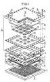
- FIG 1 eine Anordnung zur Kühlung einer auf einer Leiterplatte angeordneten Gruppe elektronischer Bauelemente als Explosionsdarstellung,
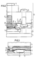
- FIG 2 einen vergrößerten Ausschnitt der Anordnung aus FIG 1 in zusammengesetztem Zustand,
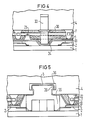
- FIG 3 einen Ausschnitt einer Anordnung mit einer der Form und Lage eines zu kühlenden Bauelements angepassten Kühlkörpers,
- FIG 4 einen Ausschnitt einer Anordnung mit einem an der festen Platte des Kühlkörpers befestigten Abstandshalter zwischen Kühlkörper und Leiterplatte,
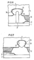
- FIG 5 einen Ausschnitt einer Anordnung mit einem an der festen Platte befestigten Abstandshalter zwischen Kühlkörper und Leiterplatte,
- FIG 6 einen Ausschnitt einer weiteren Anordnung mit einem an der Leiterplatte befestigten Abstandshalter zwischen Kühlkörper und Leiterplatte,
- FIG 7 einen Ausschnitt einer Anordnung mit einem Kühlkörper, der eine Fixierung der Kunststoff-Metall-Verbundfolie an der festen Platte durch ein eingepresstes Kunststoffteil aufweist. Gleiche Teile sind in den FIG mit demselben Bezugszeichen versehen.
- 1 shows an arrangement for cooling a group of electronic components arranged on a printed circuit board as an exploded view,
- 2 shows an enlarged detail of the arrangement from FIG. 1 in the assembled state,
- 3 shows a detail of an arrangement with a heat sink adapted to the shape and position of a component to be cooled,
- 4 shows a detail of an arrangement with a spacer fastened to the fixed plate of the heat sink between the heat sink and printed circuit board,
- 5 shows a detail of an arrangement with a spacer fastened to the fixed plate between the heat sink and the printed circuit board,
- 6 shows a section of a further arrangement with a spacer attached to the circuit board between the heat sink and the circuit board,
- 7 shows a detail of an arrangement with a heat sink, which has a fixation of the plastic-metal composite film to the fixed plate by a pressed-in plastic part. Identical parts are provided with the same reference symbols in the FIG.
Eine Leiterplatte 1, die auf einen PGA-Stecker (PGA = Pin Grid Array) 3 gesteckt ist, weist verschiedene zu kühlende Bauelemte 2 auf. Der Kühlkörper 24 setzt sich zusammen aus der festen Platte 4, der auf einem Rahmen 6 angeordneten Kunststoff-Metall-Verbundfolie 5 und der zwischen der festen Platte 4 und der Kunststoff-Metall Verbundfolie 5 angeordneten Druckmatte 7. Die feste Platte 4 ist mit dem Rahmen 6 durch Schrauben 8 verbunden. Zur Abdichtung des Kühlkörpers 24 ist ein Dichtungsring 10 zwischen Kunststoff-Metall Verbundfolie 5 und fester Platte 4 vorgesehen, der in eine auf der Innenseite der festen Platte 4 vorgesehene Nut 9 eingelegt istA
Der PGA-Stecker 3 verbindet die Leiterplatte 1 mit der nächsthöheren Hirarchieebene eines komplexen Aufbaues (nicht in der FIG dargestellt).The PGA connector 3 connects the
Zur Befestigung des Kühlkörpers 24 auf den zu kühlenden Baueleten 2 ist ein Klemmrahmen 15 vorgesehen, der die Leiterplatte 1 umfasst. Der Kühlkörper 24 ist durch Schrauben 16 auf dem Klemmrahmen 15 befestigt. Der Klemmrahmen 15 ist entweder mit dem PGA-Stecker oder einem Träger der nächsthöheren Hirarchieebene fest verbunden.A clamping
Die Anordnung kann so ausgestaltet sein, daß eine Dichtung 17 zwischen Kühlkörper 24 und Leiterplatte 1 vorgesehen ist, die in einer zur Leiterplatte 1 hin ausgerichteten Nut 18 im Rahmen 6 angeordnet ist. Eine solche Ausgestaltung dient dem Schutz der Bauelemente vor Verunreinigungen durch die Umgebung und zusätzlich zur Schadensbegrenzung bei eventuellem Leckwerden des Kühlkörpers (Failsafe). Außerdem kann eine Schutzfolie 19 (durchsichtig gezeichnet), z.B. aus Metall, zwischen der Oberfläche der Bauelemente 2 und dem Kühlkörper 24 angeordnet sein. Der Kühlkörper 24 kann Bohrungen 20 mit einer Dichtung 14 zur gemeinsamen Montage der Leiterplatte 1 mit dem Kühlkörper 24 und dem PGA-Stecker 3 auf einem Träger (nicht in der FIG dargestellt) aufweisen. Dazu sind in der Leiterplatte 1 und dem PGA-Stecker Bohrungen 21 vorgesehen.The arrangement can be designed such that a
Die feste Platte 4 weist einen Zulauf 11, einen Ablauf 12 und Versorgungskanäle 13 für das Kühlmittel auf.The fixed plate 4 has an
Die Druckmatte 7 hat eine gitterartige Struktur mit Erhebung 22 an den Gitterpunkten, die der Lage der Bauelemente 2 entsprechen. Die Druckmatte 7 kann so ausgestaltet sein, daß mehrere Erhebungen 22 über einem Bauelement 2 angeordnet sind. Die Druckmatte 7 ist aus einem gut wärmeleitfähigen Material, z.B. einem gefüllten Elastomer, hergestellt. Die Erhebungen 22 können auch aus einem weiteren gut wärmeleitfähigen Material sein, z.B. Metalldruckfe dern. Die Erhebungen 22 sollen elastisch sein, um den Druck, der auf die Bauelemente 2 wirkt, möglichst gleichmäßig über alle Bauelemente 2 zu verteilen. In zusammengesetztem Zustand der Anordnung wird die Kunststoff-Metall-Verbundfolie 5 durch die Erhebungen 22 an die Bauelemente angedrückt.The printing mat 7 has a lattice-like structure with
Die Kunststoff-Metall-Verbundfolie 5 weist eine durch Tiefziehen, z.B. Vakuum-Tiefziehen, erzeugte Ausformung 23 zur Führung des Kühlmittels 30 und in den Innenraum des Kühlkörpers 24 gerichtete Ausformungen 25, durch die Drosselstrecken für den Kühlmittelfluß gebildet werden, auf. Die Schutzfolie 19 kann zum Schutz der Kunststoff-Metall-Verbundfolie 5 gegen scharfkantige Bauelemente oder bei Verwendung einer Metallfolie zum Anlegen eines konstanten elektrischen Potentials an die Bauelementoberfläche eingesetzt werden. Zur Übersicht sind die feste Platte 4, der Rahmen 6, die Kunststoff-Metall-Verbundfolie 5 und der Klemmrahmen 15 angeschnitten dargestellt.The plastic-
Die Darstellung zeigt einen vergrößerten Ausschnitt des Randbereichs einer Kühlanordnung. Die mit den PGA-Stecker 3 verbundene Leiterplatte 1 trägt ein Bauelement 2, das mit einer Schutzfolie 19 bedeckt ist. Die Kunststoff-Metall-Verbundfolie 5 wird durch die Erhebung 22 der Druckmatte 7 an das Bauelement 2 angedrückt. Das zwischen der festen Platte 4 und der Kunststoff-Metall-Verbundfolie 5 befindliche Kühlmittel 30 wird durch den Zulauf 11 über den Versorgungskanal 13 zugeführt. Durch die Verschraubung 16 wird die feste Platte 4 mit dem Rahmen 6, auf dem sich die Kunststoff-Metall-Verbundfolie 5 befindet, fest verbunden. Dabei wird der Kühlkörper 24 durch einen in der Nut 9 der festen Platte angeordneten Dichtungsring 10 abgedichtet. Der Kühlkörper 24 ist durch Schrauben 16 auf dem Klemmrahmen 15 befestigt, der die Leiterplatte 1 umspannt.The illustration shows an enlarged section of the edge region of a cooling arrangement. The printed
Bei Anwendung der Kühlanordnung zur Kühlung von Bauelementen 32 mit besonderer Bauhöhe kann in der Kunststoff-Metall-Verbund folie 5 des Kühlkörpers 24 eine der Form und Lage des Bauelements 32 angepassten Ausformung 31 geschaffen sein. Dadurch wird der Wärmekontakt des Kühlkörpers zum Bauelement 32 verbessert und die Kunststoff-Metall-Verbundfolie 5 vor mechanischer Beanspruchung geschützt.When using the cooling arrangement for cooling
Zur Anpassung des Kühlkörpers an die mit Bauelementen bestückte Leiterplattenoberfläche sind noch weitere Ausformungen in der Kunststoff-Metall-Verbundfolie denkbar, z.B. für Oberflächenbereiche mit diskreten Verdrahtungen (nicht in der FIG dargestellt).To adapt the heat sink to the printed circuit board surface equipped with components, further shapes in the plastic-metal composite film are conceivable, e.g. for surface areas with discrete wiring (not shown in the FIG).
Die von der Bauelementbestückung der Leiterplatte abhängigen Ausformungsmuster der Kunststoff-Metall-Verbundfolie können mit CAD/CAM-Unterstückung erzeugt werden Computer Aided Design bzw. Manufactoring).The shaping patterns of the plastic-metal composite film, which depend on the component assembly of the printed circuit board, can be generated with CAD / CAM underpinning (computer aided design or manufacturing).
Bei großen zu kühlenden Oberflächen von Bauelementgruppen kann es vorteilhaft sein, einen Abstandshalter 33 zwischen fester Platte 4 und Kunststoff-Metall-Verbundfolie 5, z. B. zur Durchbiegungsbegrenzung, vorzusehen. Der Abstandshalter 33 kann dabei, z. B. durch Verschraubung, mit der festen Platte fest verbunden sein und in eine nach außen gerichtete Ausformung 34 der Kunststoff-Metall-Verbundfolie 5 geschaffene Ausformung hineinragen. Der Abstandshalter 33 muß so positioniert sein, daß er nach Befestigen des Kühlkörpers auf der Leiterplatte an einer nicht mit Bauelementen bestückten Stelle der Leiterplatte angeordnet ist. Der Abstandshalter 33 kann zum Schutz der Kunststoff-Metall-Verbundfolie 5 fest mit dieser verbunden sein, z. B. durch Klebung, was sich insbesondere beim Transport des Kühlkörpers 24 vorteilhaft auswirkt. In den Innenraum des Kühlkörpers 24 gerichtete Ausformungen 25 der Kunststoff-Metall-Verbundfolie sind so angeordnet und geformt, daß sie zur Führung des Kühlmittels 30 dienen und Drosselstrecken für den Kühlmittelfluß bilden.For large surfaces of component groups to be cooled, it may be advantageous to use a
Zur Abstandssicherung zwischen Leiterplatte 1 und fester Platte 4 kann auch ein an der Leiterplatte 1 angeordneter Abstandshalter 35 vorgesehen sein, der in eine in der festen Platte 4 geschaffene Aushöhlung 36 hineinragt und dabei gleichzeitig die Kunststoff-Metall-Verbundfolie 5 in der Aushöhlung 36 fixiert. Bei einer solchen als Bajonett-Verschluß 4/5/35 gestalteten Abstandssicherung ist eine Formung der Kunststoff-Metall-Verbundfolie 5 vor dem Verbinden der Abstandshalter 35 mit der festen Platte 4 nicht notwendig. Das Schließen des Bajonett-Verschlusses 4/5/35 bewirkt sozusagen ein Montagetiefziehen der Kunststoff-Metall-Verbundfolie 5 bei der Drehung des Abstandshalters 35.To secure the distance between printed
Die Kunststoff-Metall-Verbundfolie 5 kann auch in der Aushöhlung 36 der festen Platte durch ein eingepresstes Kunststoffteil 38 fixiert sein, das mit dem an der Leiterplatte 1 befestigten weiteren Abstandshalter 37 verbunden ist.The plastic-
Die Fixierung der Kunststoff-Metall-Verbundfolie 5 an die feste Platte 4 kann auch ohne Abstandshalter zur Leiterplatte 1 erfolgen, indem die Kunststoff-Metall-Verbundfolie 5 durch ein entsprechendes Kunststoffteil 38 in die Aushöhlung 36 der festen Platte 4 eingepresst ist.The plastic-
Der Gegenstand der Erfindung beinhaltet auch eine Anordnung zur Kühlung von Bauelementgruppen, die auf beidseitig mit einem PGA-Stecker auf einer Trägerleiterplatte befestigten Leiterplatten angeordnet sind, wobei auf beiden Leiterplatten auf den zu kühlenden Bauelementgruppen ein Kühlkörper angeordnet ist und die Kühlkörper mit einem gemeinsamen Klemmrahmen befestigt sind (nicht in den Figuren dargestellt).The subject matter of the invention also includes an arrangement for cooling component groups which are arranged on printed circuit boards fastened on both sides with a PGA connector on a carrier circuit board, a heat sink being arranged on both circuit boards on the component groups to be cooled and the heat sink being fastened with a common clamping frame are (not shown in the figures).
Claims (13)
Priority Applications (1)
| Application Number | Priority Date | Filing Date | Title |
|---|---|---|---|
| AT89106880T ATE82432T1 (en) | 1988-05-05 | 1989-04-17 | ARRANGEMENT FOR COOLING ELECTRONIC COMPONENTS, IN PARTICULAR INTEGRATED SEMICONDUCTOR CIRCUITS, WITH A LIQUID COOLANT. |
Applications Claiming Priority (2)
| Application Number | Priority Date | Filing Date | Title |
|---|---|---|---|
| DE3815386 | 1988-05-05 | ||
| DE3815386 | 1988-05-05 |
Publications (3)
| Publication Number | Publication Date |
|---|---|
| EP0340521A2 true EP0340521A2 (en) | 1989-11-08 |
| EP0340521A3 EP0340521A3 (en) | 1990-02-14 |
| EP0340521B1 EP0340521B1 (en) | 1992-11-11 |
Family
ID=6353741
Family Applications (1)
| Application Number | Title | Priority Date | Filing Date |
|---|---|---|---|
| EP89106880A Expired - Lifetime EP0340521B1 (en) | 1988-05-05 | 1989-04-17 | Fluidic-cooling arrangement for electronic components, particularly of integrated circuits with semiconductors |
Country Status (3)
| Country | Link |
|---|---|
| EP (1) | EP0340521B1 (en) |
| AT (1) | ATE82432T1 (en) |
| DE (1) | DE58902649D1 (en) |
Citations (1)
| Publication number | Priority date | Publication date | Assignee | Title |
|---|---|---|---|---|
| US4381032A (en) * | 1981-04-23 | 1983-04-26 | Cutchaw John M | Apparatus for cooling high-density integrated circuit packages |
-
1989
- 1989-04-17 DE DE8989106880T patent/DE58902649D1/en not_active Expired - Fee Related
- 1989-04-17 AT AT89106880T patent/ATE82432T1/en not_active IP Right Cessation
- 1989-04-17 EP EP89106880A patent/EP0340521B1/en not_active Expired - Lifetime
Patent Citations (1)
| Publication number | Priority date | Publication date | Assignee | Title |
|---|---|---|---|---|
| US4381032A (en) * | 1981-04-23 | 1983-04-26 | Cutchaw John M | Apparatus for cooling high-density integrated circuit packages |
Also Published As
| Publication number | Publication date |
|---|---|
| EP0340521A3 (en) | 1990-02-14 |
| ATE82432T1 (en) | 1992-11-15 |
| EP0340521B1 (en) | 1992-11-11 |
| DE58902649D1 (en) | 1992-12-17 |
Similar Documents
| Publication | Publication Date | Title |
|---|---|---|
| EP0340520B1 (en) | Convection-cooling arrangement for electrical components, particularly of integrated circuits with semiconductors | |
| EP2607121B1 (en) | Electric heating device, in particular for a motor vehicle | |
| DE112010002591B4 (en) | avionics chassis | |
| DE19518753B4 (en) | Semiconductor device and method for its production | |
| DE2825582C2 (en) | Cooling device for semiconductor elements | |
| EP1982355B1 (en) | Power electronics assembly | |
| DE19533298A1 (en) | Electronic module with power components | |
| EP2608631B1 (en) | Element which produces heat | |
| DE3942392A1 (en) | VEHICLE CONTROL UNIT ASSEMBLY | |
| EP0508286A2 (en) | Housing for installation in motor vehicles for retaining electronic components | |
| DE102011077543A1 (en) | Semiconductor device | |
| DE19630173A1 (en) | Semiconductor power module for current rectifier | |
| DE4437664A1 (en) | Electrical device and process for its manufacture | |
| EP2327286B1 (en) | Circuit housing having a heat coupling element | |
| DE102009027292A1 (en) | Inverter power module with distributed support for direct substrate cooling | |
| EP3089567A1 (en) | Electronic assembly, in particular for a transmission control module | |
| DE102012025445A1 (en) | Electrical heating device for motor car, has waving ribs arranged transverse to passage direction of medium, cooling body sealingly inserted into connector housing, and sealing element bridges gap between body and contours of housing | |
| EP0048938B1 (en) | Vertically pluggable "single-in-line" circuit module without case | |
| DE102017126716A1 (en) | Power semiconductor module with a switching device and arrangement hereby | |
| EP0340521B1 (en) | Fluidic-cooling arrangement for electronic components, particularly of integrated circuits with semiconductors | |
| DE102018207470A1 (en) | Housing for a camera and method for its manufacture | |
| DE4226816A1 (en) | Heat sink for integrated circuit - has metallic heat sink pressed onto flat surface of integrated circuit housing by bow-type spring | |
| DE102008015785B4 (en) | Electronic substrate mounting structure | |
| DE102019102505A1 (en) | Explosion-proof device with flame-proof gas flow path and heat sink | |
| DE10131601A1 (en) | Process for the production of housing parts |
Legal Events
| Date | Code | Title | Description |
|---|---|---|---|
| PUAI | Public reference made under article 153(3) epc to a published international application that has entered the european phase |
Free format text: ORIGINAL CODE: 0009012 |
|
| AK | Designated contracting states |
Kind code of ref document: A2 Designated state(s): AT BE CH DE FR GB IT LI NL |
|
| PUAL | Search report despatched |
Free format text: ORIGINAL CODE: 0009013 |
|
| AK | Designated contracting states |
Kind code of ref document: A3 Designated state(s): AT BE CH DE FR GB IT LI NL |
|
| 17P | Request for examination filed |
Effective date: 19900307 |
|
| RAP1 | Party data changed (applicant data changed or rights of an application transferred) |
Owner name: SIEMENS NIXDORF INFORMATIONSSYSTEME AG |
|
| 17Q | First examination report despatched |
Effective date: 19920407 |
|
| GRAA | (expected) grant |
Free format text: ORIGINAL CODE: 0009210 |
|
| RAP1 | Party data changed (applicant data changed or rights of an application transferred) |
Owner name: RICHTER, HANS-JUERGEN |
|
| AK | Designated contracting states |
Kind code of ref document: B1 Designated state(s): AT BE CH DE FR GB IT LI NL |
|
| PG25 | Lapsed in a contracting state [announced via postgrant information from national office to epo] |
Ref country code: IT Free format text: LAPSE BECAUSE OF FAILURE TO SUBMIT A TRANSLATION OF THE DESCRIPTION OR TO PAY THE FEE WITHIN THE PRE;WARNING: LAPSES OF ITALIAN PATENTS WITH EFFECTIVE DATE BEFORE 2007 MAY HAVE OCCURRED AT ANY TIME BEFORE 2007. THE CORRECT EFFECTIVE DATE MAY BE DIFFERENT FROM THE ONE RECORDED.SCRIBED TIME-LIMIT Effective date: 19921111 Ref country code: NL Effective date: 19921111 Ref country code: FR Effective date: 19921111 Ref country code: BE Effective date: 19921111 Ref country code: GB Effective date: 19921111 |
|
| REF | Corresponds to: |
Ref document number: 82432 Country of ref document: AT Date of ref document: 19921115 Kind code of ref document: T |
|
| REF | Corresponds to: |
Ref document number: 58902649 Country of ref document: DE Date of ref document: 19921217 |
|
| EN | Fr: translation not filed | ||
| NLV1 | Nl: lapsed or annulled due to failure to fulfill the requirements of art. 29p and 29m of the patents act | ||
| PG25 | Lapsed in a contracting state [announced via postgrant information from national office to epo] |
Ref country code: AT Effective date: 19930417 |
|
| PG25 | Lapsed in a contracting state [announced via postgrant information from national office to epo] |
Ref country code: CH Effective date: 19930430 Ref country code: LI Effective date: 19930430 |
|
| GBV | Gb: ep patent (uk) treated as always having been void in accordance with gb section 77(7)/1977 [no translation filed] |
Effective date: 19921111 |
|
| PLBE | No opposition filed within time limit |
Free format text: ORIGINAL CODE: 0009261 |
|
| STAA | Information on the status of an ep patent application or granted ep patent |
Free format text: STATUS: NO OPPOSITION FILED WITHIN TIME LIMIT |
|
| 26N | No opposition filed | ||
| REG | Reference to a national code |
Ref country code: CH Ref legal event code: PL |
|
| PG25 | Lapsed in a contracting state [announced via postgrant information from national office to epo] |
Ref country code: DE Effective date: 19940301 |