EP0339087B1 - Device for imaging small cavities - Google Patents
Device for imaging small cavities Download PDFInfo
- Publication number
- EP0339087B1 EP0339087B1 EP89901828A EP89901828A EP0339087B1 EP 0339087 B1 EP0339087 B1 EP 0339087B1 EP 89901828 A EP89901828 A EP 89901828A EP 89901828 A EP89901828 A EP 89901828A EP 0339087 B1 EP0339087 B1 EP 0339087B1
- Authority
- EP
- European Patent Office
- Prior art keywords
- signals
- transducer
- transducer elements
- array
- set forth
- Prior art date
- Legal status (The legal status is an assumption and is not a legal conclusion. Google has not performed a legal analysis and makes no representation as to the accuracy of the status listed.)
- Expired - Lifetime
Links
Images


Classifications
-
- G—PHYSICS
- G01—MEASURING; TESTING
- G01S—RADIO DIRECTION-FINDING; RADIO NAVIGATION; DETERMINING DISTANCE OR VELOCITY BY USE OF RADIO WAVES; LOCATING OR PRESENCE-DETECTING BY USE OF THE REFLECTION OR RERADIATION OF RADIO WAVES; ANALOGOUS ARRANGEMENTS USING OTHER WAVES
- G01S7/00—Details of systems according to groups G01S13/00, G01S15/00, G01S17/00
- G01S7/52—Details of systems according to groups G01S13/00, G01S15/00, G01S17/00 of systems according to group G01S15/00
- G01S7/52017—Details of systems according to groups G01S13/00, G01S15/00, G01S17/00 of systems according to group G01S15/00 particularly adapted to short-range imaging
- G01S7/52023—Details of receivers
- G01S7/52025—Details of receivers for pulse systems
- G01S7/52026—Extracting wanted echo signals
- G01S7/52028—Extracting wanted echo signals using digital techniques
-
- A—HUMAN NECESSITIES
- A61—MEDICAL OR VETERINARY SCIENCE; HYGIENE
- A61B—DIAGNOSIS; SURGERY; IDENTIFICATION
- A61B8/00—Diagnosis using ultrasonic, sonic or infrasonic waves
- A61B8/12—Diagnosis using ultrasonic, sonic or infrasonic waves in body cavities or body tracts, e.g. by using catheters
-
- A—HUMAN NECESSITIES
- A61—MEDICAL OR VETERINARY SCIENCE; HYGIENE
- A61B—DIAGNOSIS; SURGERY; IDENTIFICATION
- A61B8/00—Diagnosis using ultrasonic, sonic or infrasonic waves
- A61B8/44—Constructional features of the ultrasonic, sonic or infrasonic diagnostic device
- A61B8/4444—Constructional features of the ultrasonic, sonic or infrasonic diagnostic device related to the probe
- A61B8/445—Details of catheter construction
-
- G—PHYSICS
- G01—MEASURING; TESTING
- G01S—RADIO DIRECTION-FINDING; RADIO NAVIGATION; DETERMINING DISTANCE OR VELOCITY BY USE OF RADIO WAVES; LOCATING OR PRESENCE-DETECTING BY USE OF THE REFLECTION OR RERADIATION OF RADIO WAVES; ANALOGOUS ARRANGEMENTS USING OTHER WAVES
- G01S15/00—Systems using the reflection or reradiation of acoustic waves, e.g. sonar systems
- G01S15/88—Sonar systems specially adapted for specific applications
- G01S15/89—Sonar systems specially adapted for specific applications for mapping or imaging
- G01S15/8906—Short-range imaging systems; Acoustic microscope systems using pulse-echo techniques
- G01S15/8909—Short-range imaging systems; Acoustic microscope systems using pulse-echo techniques using a static transducer configuration
- G01S15/8915—Short-range imaging systems; Acoustic microscope systems using pulse-echo techniques using a static transducer configuration using a transducer array
- G01S15/892—Short-range imaging systems; Acoustic microscope systems using pulse-echo techniques using a static transducer configuration using a transducer array the array being curvilinear
Definitions
- the present invention relates to a device according to the preamble of claim 1.
- US-A-4,325,257 discloses a device of this type and more specifically involves a digital synthetic-focus, acoustic imaging system which is operative in real time and includes one or more electro-acoustic transducers arranged to receive broadband pulses from a pulse generator for excitation of acoustic pulses which are directed into the region under observation. Signals reflected from an object or discontinuity in the region are received by the same transducers, and after inverse filtering and nonlinear amplification are converted to digital signals.
- These digital signals are stored in separate high speed random access memory units for storage, but are subsequently time-equalized through use of a programmed focus memory unit prior to delivery to a digital adder and thence through a digital-to-analog converter for ultimate intensity modulation on a raster scanned display unit which provides the real time image.
- heart disease is the leading cause of death and disability.
- One particular kind of heart disease is atherosclerosis, which involves the deposition of fatty material on the inside of vessel walls throughout the body (commonly called “plaque"). As the plaque collects, the artery narrows and blood flow is restricted. If the artery narrows too much, the heart muscle nourished by the artery receives insufficient oxygen and a myocardial infarction or "heart attack” can occur. Atherosclerosis can occur throughout the human body, however, it is most life threatening within the coronary vasculature.
- Coronary artery bypass grafts or "open heart” surgery can be performed to bypass blocked artery segments.
- Other, less invasive procedures are available. For example, some blockages may be dissolved by chemical treatment.
- PTCA percutaneous transluminal coronary angioplasty
- a catheter with an expandable section on its end is placed within the narrowed artery and inflated to compact the plaque against the vessel wall, thereby relieving the blockage.
- Coronary angiography involves the placement of the end of a catheter at the beginning of the coronary vasculature. A small amount of radiopaque dye is injected, and a X-ray motion picture is taken while the dye is pumped through the vessels. The physician then examines the pictures and looks for any telltale narrowing of the blood flow opacified by the radiopaque dye. By the number and degree of such narrowing, the course of treatment can be determined.
- Angiography has the extreme limitation of indicating only where the blood is within the vessel; it reveals nothing of the condition of the inside of the vessel and the vessel wall itself. Furthermore, most angiography machines present virtually only one-dimensional projections of where blood flow exists. Because of this imaging limitation, the complex structures within the coronary vascular often exhibit quite ambiguous images.
- MRI magnetic resonance imaging
- ultrasound ultrasound have become important diagnostic tools for cardiac assessment.
- MRI magnetic resonance imaging
- ultrasound ultrasound
- the image resolution is not sufficient to allow assessment of the condition of the walls of the vessel.
- Conventional ultrasound scanning also suffers from lack of resolution.
- high frequency (hence, high resolution) ultrasound has been used during open heart surgery to access the coronary arteries. This method requires the opening of the chest cavity to expose the heart surface and is hence limited in its application.
- in vivo ultrasonic imaging of the human body creates the potential for access to a wealth of information regarding the condition of a patient's vasculature that is currently only at best indirectly available from other sources.
- the information received from in vivo imaging may be used as a diagnostic tool to help determine patient treatment, or as a surgical tool, supplementing angiography in PCTA.
- a further limitation of the known device is the fixed delays it provides for focusing an image. Such fixed delays do not provide satisfactory images for identification of tissue structures.
- a dynamic focusing feature is needed to provide an optimal focus at a plurality of points in the imaging plane.
- One approach to implementing such a dynamic focusing feature is a so-called “synthetic focus” or “synthetic-aperture” approach disclosed in above reference US-A-4,325,257.
- the known apparatus comprises a catheter having an optical fiber for transmitting laser irradiation and an ultrasonic transducer mounted at the tip of the catheter for transmitting and receiving ultrasonic signals.
- the apparatus further comprises a transmitting unit for generating electrical impulses for activating the ultrasonic transducer, a receiving unit for displaying electrical signals from the ultrasonic transducer and a laser.
- Arteriosclerotic plaque deposits are identified by the ultrasonic echoes which result from transmitted ultrasonic signals and are removed by laser irradiation.
- a still further advantage of the present invention is its operation at very low power dissipation in vivo in order to prevent heating of surrounding tissue and expansion of parts.
- the present invention provides an imaging device whose in vivo portion may be mounted to a positioning device such as a catheter, which allows the use of, for example, conventional guiding catheters and guidewires.
- a positioning device such as a catheter
- the imaging device is suitable for incorporation into recent catheter systems, and allowing for the continued use of, for example, guiding catheters and guidewires, in conjunction with catheter-based diagnostic and therapeutic procedures such as angioplasty, regional therapy for dissolving plaque and the like.
- the invention provides an in vivo imaging device for producing real-time images of small, moving or stationary cavities and surrounding tissue structure that is uniquely and advantageously constructed using a conventional catheter assembly fitted at its end with a probe assembly for transmitting and receiving ultrasonic signals from elements of an array of ultrasonic transducers incorporated into the probe assembly.
- the transducer elements are selected and controlled by an in vitro electronic signal processing and imaging unit which transmits excitation and control signals via a transmission cable to integrated circuitry on-board the body of the probe assembly.
- the integrated circuitry routes excitation signals to the transducer elements in a predetermined sequence.
- the body of the probe assembly not only supports the array of transducer elements and the integrated circuitry, but also accommodates conventional catheter devices such as a catheter guidewire that may be threaded through the probe assembly.
- the number of wires in the transmission cable connecting the integrated circuitry to the processing and imaging unit are minimized by providing for a multiplexing task at the integrated circuitry on-board the probe assembly. Due to the relatively few number of conductors comprising the transmission cable, there is a high degree of physical flexibility achieved, and there is a relatively small cross-section obtained, which makes the device convenient for use within the limited confines of its intended operating environment.
- the integrated circuits also buffer excitation signals from the transmission cable which are directed to a selected element in accordance with a preferred image reconstruction scheme. These pulses are converted into ultrasonic waves by the transducer elements. The echoes or reflections from the environment are received by the transducer elements, converted back into electrical signals which are relatively weak, and buffered by the integrated circuits so that the weak signals are boosted before being directed onto the transmission cable for delivery to the signal processing and imaging unit.
- the piezoelectric material used for the array of transducer elements is preferably continuous in order to simplify construction of the probe. Further, the material may be characterized by a high internal electrical impedance resulting in weak electrical output current in response to ultrasonic echos. In order to provide a wide beam pattern as desired by the preferred imaging technique, the transducer elements adjacent an element or elements receiving an excitation signal are shunted to a low impedance to confine the active region to the selected transducer or transducers.
- signals indicative of the reflections or echos of ultrasonic acoustic waves are processed at extremely high speeds such that signal digitization and dynamic digital signal averaging, with respect to each individual or group of transducer elements, may be implemented, thereby producing resultant signals having a very high dynamic range.
- These resultant signals are then processed into diagnostic information in the form of, for example, images.
- the signals are preferably processed using a synthetic-aperture approach wherein dynamic time delays and weighting factors are used to produce a myriad of individually focused points throughout the entire image plane, thereby resulting in real-time, high resolution diagnostic images of the cavity and surrounding structure.
- an alternative application is the use of the invention on the end of a catheter without the incorporation of a balloon.
- a specific example of such a use is a pharmaceutically therapeutic use where cholesterol-inhibiting drugs are used for regional therapy and the imaging device of the invention is used to monitor the effectiveness of the drugs in removing plaque.
- Another specific example of an alternative use in a physical therapeutic use such as measuring blood flow rates (using Dopler sound imaging in conjunction with invention) or determining sizes and locations of gall stones and the like.
- Yet another example of an alternative application is the incorporation of the invention into a catheter in conjunction with a laser or like devices for burning plaque in the arteries.
- a buildup of fatty material or plaque 12 in a coronary artery 14 of a heart 16 may be treated in certain situations by inserting a balloon 18, in a deflated state, into the artery via a catheter assembly 20.
- the catheter assembly 20 is a three-part assembly, having a guide wire 19, a guide catheter 20a for threading through the large arteries such as the aorta 22 and a smaller diameter catheter 20b that fits inside the guide catheter. After a surgeon directs the guide catheter 20 and the guide wire 19 through a large artery leading to the aorta 22, the smaller catheter 20b is inserted.
- the guide wire is first extended into the artery, followed by catheter 20b, which includes the balloon 18 at its tip.
- an ultrasonic imaging device including a probe assembly 24 housed in the tip of the catheter 20b provides a surgeon with a cross-sectional view of the artery on a video display 26.
- Signals from the probe assembly 24, indicative of reflected ultrasonic waves, are transferred along a cable 28 to a signal processor 30 located outside the patient.
- the catheter 20b ends in a three-port junction 29 of conventional construction that couples the catheter to an inflation source 31, a guide wire source and the signal processor 30.
- the inflation and guide wire ports 29a and 29b, respectively, are of conventional PTCA catheter construction.
- the third port 29c provides a path for the cable 28 to connect with the signal processor 30 and video display 26 via an electronic connector 33.
- the invention is not intended to be limited to a PTCA environment.
- the port 29a may be an injection site for the drug instead of an inflation source and, of course, the balloon 18 at the end of the catheter 20b is not needed.
- the imaging device provides an image 32 on the display 26 that indicates when the balloon 18 is within a partially blocked area of the coronary artery 14 as is best seen in FIGS. 2-4.
- the tip of the catheter 20a containing the probe assembly 24 is moved past the blocked area in order to bring the following balloon 18 into the area as shown in FIG. 3.
- the balloon 18 is thereafter inflated so as to compress the plaque 12 causing the blockage.
- the cardiologist may check the results of the PTCA procedure, by slightly withdrawing the catheter 20a in order to bring the tip and the associated probe assembly 24 back into the blocked area as shown in FIG. 4. If the PTCA procedure was successful, the image 32 on the video display screen 26 will show the lumen of the artery 14 has increased in cross-sectional area.
- the probe assembly 24 is constructed to be sufficiently small to fit in cavities of approximately the size of a human coronary artery as shown in the illustrated embodiment.
- a polymer piezoelectric material is used to provide transducer elements for generating and receiving ultrasonic acoustical waves.
- the polymer piezoelectric material is continuous in order to provide for ease of manufacture.
- the piezoelectric material forms a ring 44 for viewing in a plane P (FIG. 5) passing through the material and normal to its surface; however, it will be appreciated that in other applications or for viewing in alternative planes, the piezoelectric material may take other forms.
- the natural frequency of the material it is necessary that the natural frequency of the material be much higher than the chosen operating frequency. In the illustrated embodiment, a frequency of 20MHz is chosen as the operating frequency.
- piezoelectric polymers are suitable for use as the ring 44.
- An acceptable material must have the following characteristics. The material must, of course, have good sensitivity characteristics for detecting reflected ultrasonic waves. Because of the small size and cylindrical shape of the ring 44, however, the piezoelectric material must also be capable of being formed into a suitable shape of very small diameter (e.g., a cylinder of about 1.5mm. diameter). For example, the material may start as a flexible sheet or, if it is not flexible, it may be formed directly into the desired shaped by deposition or other well-known forming processes. Also, because the material is continuous, it must be characterized by good acoustic behavior.
- the invention includes electronics that aid in eliminating shear waves or ringing.
- the piezoelectric material must be well matched to the human tissue immediately surrounding the probe assembly 24.
- the copolymer P(VDF-T r FE) having a thickness of approximately nine (9) microns.
- PVDF polyvinyl styrene
- copolymer P(VDF-TFE) having a thickness of approximately nine (9) microns.
- PZT polymers and ceramics
- a depositable material such as ZnO.
- a continuous ring 44 of material is much more preferable than an individual piece of piezoelectric material for each transducer element.
- the manufacturing complexities avoided and the cost savings obtained are considerable if a continuous ring of piezoelectric material is used. For example, using a continuous material, there is no need to cut individual elements. Cutting individual elements of the very small size requiring for the probe body 42 would be very difficult and expensive.
- the piezoelectric polymer material comprising ring 44 must be supported, and the body 42 serves the purpose. Since acoustic energy is reflected at interfaces between regions of differing acoustic impedance, a hard backing for the transducer array is necessary to ensure that most of the ultrasonic energy is not absorbed by the backing.
- an alumina composition i.e., Al2O3 of the body 42 provides the necessary hard backing.
- the body 42 of the probe assembly 24 has box-shaped and cylindrically-shaped sections 42a, 42b, respectively.
- a third transitional section 42c joins the other two sections 42a, 42b by tapering the body 42 along its axial length from the cylindrical section to the box-shaped section.
- the probe assembly 24 is sufficiently small to fit inside areas such as the coronary artery 14, it preferably has the following approximate dimensions: Diameter of cylindrical section 42b -- 1.5 millimeters; width of one side of box-shaped section 42a -- 3/4 millimeter; axial length -- 3.0 millimeters; diameter of axial bore 40 -- 1/2 millimeter.
- the body 42 is formed by known injection molding techniques. Because the dimensions of the body 42 are small and the tolerances are small (e.g., the tolerance on the outer diameter of the cylindrically-shaped section 42b is 1.22 microns (500 microinches)), very precise machining is required for the injection mold. Furthermore, the small size of the body 42 makes it impractical to polish after molding. Therefore, it is important that the injection molding process provides a smooth surface.
- the body 42 of the probe assembly not interface with conventional PTCA, regional drug therapy and other therapeutic or diagnostic procedures that utilize catheters and may advantageously incorporate the invention in order to improve those procedures. Therefore, in order to secure the probe assembly 24 to the tip of the catheter 20b, a conventional guide wire lumen inside the catheter is telescopically fitted over a mating guide wire lumen 38 forming the central bore 40 in the probe assembly as best seen in FIG. 5. To further secure the probe assembly 24, the end of the catheter 20b is joined to the probe assembly by way of an epoxy material 41 encapsulating and protecting the integrated circuits 54 mounted on the rectangular section of the body.
- the ability of the catheter 20b to perform a conventional catheterization procedure is uneffected, since the bore 40 allows the guide wire to exit the tip of the probe assembly 24.
- the bore 40 is lined with, for example, kapton.
- the outside of the probe assembly 24 is covered by a protective sheath (not shown) made of, for example, parylene.
- the catheter 20b supports the balloon 18 at its one end.
- the balloon 18 is positioned adjacent the probe assembly 24 and is isolated from ambient conditions by sealing the two ends of the balloon to the catheter in a conventional manner.
- the area of the catheter 20b covered by the balloon 18 includes a series of holes 43 for communicating fluid between the balloon and an inflation source 31 in FIG. 1.
- Each wire in the cable 28 is formed of conventional "magnet" wire -- i.e., a solid conductor protected by an insulating coating.
- a ribbon of copper (not shown) is spiraled in order to provide a ground shield for the signals carried by the cable 28.
- the copper ribbon is provided with a protective insulating coating.
- a plurality of underlying conductive traces 46 are formed on the surface of the cylindrical section 42b of the body 42 and underlie the ring 44 of continuous piezoelectric material.
- the outer surface of the ring 44 of piezoelectric material has a thin coating of metallic material.
- Each element of the array is defined by an area of the ring 44 overlapping the conductive traces as generally indicated in FIG. 7.
- a film of an epoxy glue holds the inner surface of the ring of material to the surface of the probe body 24.
- the ring 44 may be formed of the piezoelectric material as a cylinder or it may be a flat sheet that is rolled and joined at a seam. Preferably, the ring 44 is a seamless cylinder.
- the conductive traces 46 are evenly spaced about the circumference of section 42c of the body 42. Such a construction results in the elements of the array being aligned with their length axes parallel to the length axis of the body 42. Preferably, there are 64 conductive traces 46 and, therefore, 64 transducer elements.
- the body 42 is first coated with a well-known titanium and tungsten mixture, using conventional deposition techniques. Over the titanium and tungsten mixture, a layer of gold is deposited onto the body 42. To etch the conductive pattern, the body 42 is held in a jig (not shown) and state-of-the-art laser oblation methods are used to etch the pattern on each side of the box-shaped section 42a, proceeding one side at a time. For the cylindrically-shaped and transitional sections 42b and 42c, respectively, each is etched separately by incrementally rotating the body in the jig.
- the body 42 In addition to not absorbing significant amounts of ultrasonic energy, the body 42 must not have resonant effects due to the energy reverberating in the cylindrically-shaped section 42b that are within the frequency region of operation. Such reverberation is evidenced by a notch in the frequency response of each element in the array. The frequency position of the notch is controlled by keeping the alumina under the transducer thin.
- the cylindrical section 42b of the probe body 42 is recessed so that the body defines a thin annular wall 48 for supporting the ring 44 of piezoelectric material.
- the frequency response spectrum of the ring 44 of piezoelectric material includes a notch N whose frequency position in the spectrum is effected by the following factors: (1) the thickness or the wall 48, and (2) the acoustic velocity of the sound within the material comprising the wall.
- the notch N is positioned outside the frequency region of the transducer array (e.g., 15-25MHz).
- the annular wall 48 has a thickness d as illustrated in FIG. 8 and destructive interference forming the notch N in FIG. 9 occurs when the half-wavelength ⁇ 2 of the ultrasonic waves is approximately equal to the thickness d. ⁇ 2 ⁇ d More generally, destructive resonance occurs at all the odd half-wavelength harmonics.
- n is an odd integer - i.e., 1, 3, 5, etc.
- the first notch (N in FIG. 9) should be at no lower a frequency than, for example, 28MHz. Knowing the velocity V of the ultrasound waves through the alumina, equation (1) can be rewritten as V 2f ⁇ d where f is the frequency of the ultrasound waves. Substituting the values for equation (3) gives Therefore, the thickness of the annular wall 48 should be .182 mm or less. In order to fill the recess 50 formed by the annular wall 48 without significantly effecting the acoustic properties of the probe body, an acoustic backing material 52 such as urethane is used.
- small piezoelectric transducers made from copolymers such as P(VDF-T r FE) are characterized by very high electrical impedance values (e.g., 30K ohms for one element), very low current signal levels are generated by each array element in response to reflected acoustic waves.
- transimpedance amplifiers are located on-board the probe assembly 24 and in close physical proximity to the ring 44 of piezoelectric material.
- the amplifiers provide current-to-voltage amplification in a linear relationship where one microamp produces approximately 750 microvolts.
- the probe assembly 24 includes a plurality of the integrated circuit chips 54 (four in the preferred embodiment).
- Each chip 54 includes current amplifiers as discussed in greater detail in connection with FIG. 11 that receive low current signals from the high impedance transducer elements and provide the low impedance (e.g., 50 ohms) cable 28 with a high voltage signal.
- the actual amplifier devices for each channel are current amplifiers with an approximate gain of 15 from transducer element to cable, the overall effect of the amplifiers is one of transimpedance since the signal is received from a high impedance current source (the element) and delivered to a lower impedance load as a voltage (the cable and its termination).
- FIG. 10 illustrates the frequency response of an element in the transducer array with the transimpedance amplifier and additional voltage amplification.
- the four integrated circuit chips 54 are of an inverted chip design and are bonded to conductive pads 56 formed on the box-shaped section 42a of the probe body.
- the pads 56 interconnect each of the four chips 54 and also provide a connection betwen the chips and the cable 28 within the catheter 20a that connects the chips to the signal processor 30 outside of the patient.
- the strips extend along the axial length of the probe 24, beyond the ring 44 of piezoelectric material and down the transitional section 42c to conductors 58 on the underside of the chips 54.
- the cable 28 from the signal processor 30 provides communication channels between the processor and the integrated circuits 54, using a minimum number of wires.
- the four integrated circuit chips 54 provide a multiplexing function that distributes excitation pulses from the signal processor 30 to a predetermined one or ones of the transducer elements.
- a single pair of wires T+, T- in the cable carry the excitation signals as differential pulses in series format from the signal processor 30 to the chips 54.
- each excitation signal is routed to an appropriate one of the transducer elements in order to execute an excitation sequence used by the preferred image reconstruction technique.
- Each chip 54 as illustrated in FIG. 11 has 16 channels 60 associated with 16 of the 64 transducer elements XD1 - XD64 defined by the ring 44 of piezoelectric material and the conductive traces 46. Each chip 54 is responsible for sequentially transmitting and receiving ultrasonic signals on one of its associated 16 channels. At any given time, exactly one of the chips 54 will be designated as active, where "active" indicates the one chip 54 that is currently exciting one of its associated transducer elements XD N . Furthermore, at any given time only one of the 16 channels 60 on an active chip 54 is free to be excited by an excitation signal or to receive reflections or echos. The electrical signals generated from the reflections impinging on the free transducer element are amplified and sent via the transmission cable line 28, to the externally located signal processor 30 as explained more fully hereinafter.
- Each excitation signal intended for one of the transducer elements XD N travels down the transmission lines T+, T- as a differential pulse.
- the excitation signal consists of two closely spaced short duration (of approximately 25 nanoseconds) pulses.
- An excitation signal of this form generally provides significantly more transmitted acoustic energy from an excited transducer than would a single pulse.
- an optimization is realized between maximizing the transmitted acoustic amplitude and maintaining reasonable image resolution.
- the particular form of this signal can be modified to maximize the desired features of the signal.
- this differential pulse is received and amplified by the differential pulse receiver amplifier 62 as shown in FIG. 11.
- the differential pulse is supplied to the T+ and T- transmission cable lines 28 via an analog buffer (not shown) which converts a received unipolar excitation signal from the signal processor 30 into the desired differential pulse.
- only one of the chips 54 receives timing signals on lines CDATA and CCLK and an excitation signal on line T+,T- from the transmission cable 28, although all four of the chips are capable of receiving these signals because of their identical structure.
- This one chip 54 receiving timing and excitation signals cooperates with the other three chips in a master-slave relationship where the signal lines CDATA, CCLK and T+,T- are used to generate a system clock (i.e., SYS CLK) for synchronizing all four chips 54, and to distribute the excitation signal T+,T- by way of line SYSTRAN .
- SYS CLK system clock
- bus lines are common to all the chips and are connected between adjacent chips by extensions 56a of conductive pads 56, which are formed around the box-shaped section 42a of the body 42 (FIGS. 6 and 8).
- the bus comprises lines I REF , SYSTRAN , ANA OUT, SYS CLK, V+ and V-.
- the schematic diagram of one of the chips in FIG. 11 will be treated as the master chip which receives the signal lines CDATA, CCLK, T+,T- and V+, V- from the transmission cable 28.
- the SYSTRAN line delivers the excitation signals to all the chips 54, and as will be described in more detail later, other signals are used to control the application of the excitation signals to the 64 transducer elements XD1 - XD64.
- FIG. 11 shows 16 elements on one of four chips for a total of 64.
- a receiver amplifier 62 on the chip 54 receives the excitation signal in its differential pulse form and converts it to a unipolar form. From the receiver amplifier 62, the excitation signal is passed through an inverting buffer 64 which supplies an inverted version of the excitation signal to all the chips through the common SYSTRAN line.
- the master chip 54 responds to external bias currents on lines T+, T- by generating a cable bias current I CABLE BIAS which is used as a bias reference signal for indicating which chip 54 is the master chip receiving the timing and excitation signals.
- the reference current I REF is generated and distributed to all the chips 54 for producing the necessary bias voltages on the other chips. Specifically, the current I REF is generated at the drain of MOSFET 66 in the transistor current mirror 64, 66 on the master chip 54.
- the reference current I REF is used by bias generators 70, 72 to produce bias voltages for a delay buffer 74 and the individual channel amplifiers 60b which are discussed more fully hereinafter.
- the cable bias current I CABLE BIAS is generated by a current mirror transistor configuration comprising two p-channel MOSFET transistors 64, 66 with their gates connected in common, and their sources connected to a positive supply voltage V+, as shown in FIG. 11.
- the gate of one MOSFET transistor is also connected to its drain which in turn is connected to the T+ and T- lines of cable 28.
- the voltage of the T+ and T- transmission cable lines of the master chip 54 are held at a voltage lower than the positive supply voltage V+, and as a result of this lower voltage, the cable bias current I CABLE BIAS flows from the common gate and drain connection of the transistor 64 located on the master chip 54.
- the cable bias current I CABLE BIAS is utilized to assert a "M" line on the master chip 54.
- the other chips 54 will have no cable bias current flowing, due to the absence of the T+ and T- transmission cable connections, and will have a negated "M” line.
- a comparator 68 is used to compare the voltage level of the cable bias current on the line I CABLE BIAS to a predetermined comparator reference voltage V R1 derived from series resistors R1 and R2.
- the line for a cable bias current I CABLE BIAS remains at the supply voltage V+ which is greater than the reference voltage V R1 , thereby causing the comparator 68 to negate the "M" line which designates the chip as a slave chip. Otherwise, if the T+ and T- transmission lines of the cable 28 are connected, there will be a voltage drop on the I CABLE BIAS line. This reduced voltage level will be lower in magnitude than the comparator reference voltage V R1 , thereby causing the comparator 68 to activate the "M" line which designates the chip as the master chip.
- Timing signals received by the CDATA and CCLK lines are also dependent upon reference voltages generated by the current I REF or I CURRENT BIAS .
- the signal on the CDATA line is input to an amplifier 76 along with a reference voltage V R2 generated at the node connecting resistors R3 and R4 from the I CABLE BIAS circuitry.
- This input amplifier 76 insures the proper voltage levels on the chip 54.
- the output of this input amplifier 76 is sent to an inverting buffer 78 that acts as a transmission gate which is controlled by the state of the "M" line.
- the CCLK transmission line from cable 28 it is connected through an input amplifier 80 along with the aforementioned reference voltage V R2 .
- the output of amplifier 80 is sent to a non-inverting transmission gate buffer 82, which in turn produces the clock signal SYS CLK on the common bus line for distribution to all the chips 54.
- This clock signal SYS CLK is used to sequence the shift register 84 on each chip 54 in order to sequentially activate the 64 channels 60 on the probe assembly 24 as explained more fully hereinafter.
- the sequential stepping through the 16 channels 60 on each of the chips 54 is accomplished by shifting a single logic bit through the 16 bit shift register 84.
- the logic outputs of the shift register 84 of an inactive chip 54 are all negated. Therefore, at any given time exactly one of the 16 outputs of the shift register 84 on one of the chips 54 is "active" and all the other 63 outputs are disabled.
- the CLK input to the shift register 84 driven by the SYS CLK bus line, allows the logic bit to be sequenced from one output Q N to the next Q N+1 .
- Each of the output lines Q N of the shift register 84 is used to sequentially and individually enable the transducer channels 60 on the chip 54 by way of a NAND gate 60a and an enable input to the correponding channel amplifier 60b. As indicated in FIG. 11, there is a none-to-one correspondence between the individual outputs Q N of the shift register 84 and the individual transducer channels 60. For example, output Q1 is associated with channel 1, output Q2 is associated with channel 2, etc.
- a separate chip select signal CS is asserted by the one of the four chips 54 that is currently activating one of its channels 60 for the generation and detection of ultrasonic acoustic signals. At this time, chip select lines CS of the other three chips 54 are negated.
- the CS signal is asserted by using one clocked SR flip-flop 88 and one unclocked SR flip-flop 90 as explained more fully hereinafter.
- the first bias generator 70 receives as an input the common reference current I REF which is generated on the master chip 54, and utilizes this signal to produce the desired bias voltage on a BUF BIAS line for the delay buffer 74. Since the presence of a bias voltage on the BUF BIAS line is only needed for a particular chip 54 when one of its channels 60 is active, the CS (inverted chip select) line is used to selectively activate and de-activate the bias generator 70.
- the second bias generator 72 is used to provide the proper bias voltage on a AMP BIAS line for the transducer channel amplifiers 60b.
- the second bias generator 72 is selectively activated and de-activated by the logical ORing of the CHIP TRANS line (an inverted SYSTRAN line) and a WAIT line from the dealy buffer 74 at OR gate 73.
- CHIP TRANS line an inverted SYSTRAN line
- WAIT line from the dealy buffer 74 at OR gate 73.
- the bias voltage AMP BIAS line is supplied to the amplifiers by the second bias generator 72 after the associated transducer element XD N has been excited to generate ultrasonic acoustic waves.
- the delay buffer 74 serves an important timing role in the operation of the chips 54.
- a particular embodiment of the delay buffer 74 is illustrated in FIG. 12. It will be appreciated, however, that many alternative designs may also provide the desired timing signals of WAIT and BUF RESET.
- the delay buffer 74 uses the excitation signal on the CHIP TRANS line as its input along with the bias voltage BUF BIAS from the first bias generator 70, the delay buffer 74 produces three important output signals. Specifically, upon receiving an excitation signal on the CHIP TRANS line (via the lines T+ and T- of the transmission cable 28), the delay buffer 74 sets the WAIT output line active, thereby disabling the second bias generator 72 from producing a bias voltage AMP BIAS for the channel amplifiers 60b of the channels 60. After sufficient time has passed to ensure the WAIT line is high and the channel amplifiers 60b are deactivated (a delay is provided by the inverters 101 in FIG.
- the delay buffer 74 sends the excitation signal on the BUF TRANS bus line, thereby sending the excitation signal to all of the transducer channels 60.
- the BUF TRANS line is NANDed with one of the Q N outputs of shift register 84 by the NAND gate 60a and buffer FET 60e. Because only one NAND gate 60a in the channels 60 of chip 54 has both inputs active, only one of the transducer element XD1 - XD16 is excited.
- the beam pattern formed by the excitation of an element is optimized during both transmission and reception of ultrasonic waves by providing low impedance paths through elements adjacent the excited element.
- the low impedance characteristic of adjacent elements minimizes the aperture width, thereby creating a beam of maximum width.
- the widest beam is most desirable since it provides the greatest overlap with adjacent beams and hence the most information during reconstruction of an image.
- each channel 60 includes a MOSFET 60d controlled at its gate by a Q n signal (i.e., Q n from shift register 84 inverted by inverter 60f).
- an active Qn signal causes the node of the transducer element (i.e., the conductive trace 46) to be effectively grounded, thereby shunting the high impedance transducer elment.
- the node for the transducer element remains grounded and the element shunted until the associated Qn line from the shift register 84 becomes active.
- Qn active the FET 60d is turned off and the transducer node is released from a ground potential so that it may deliver an excitation signal to the transducer element XD N .
- the BUF RESET line is briefly asserted by the delay buffer 74 in order to clamp the MOSFET transistors 60c to ground such that the excited transducer element is effectively shunted in order to sweep off any charge at the node of the excited element (to rapidly return the amplifier 60b to its quiescent bias state) and quell any transient signals or "ringing" at the input to the amplifier 60b.
- the signal on the BUF RESET line resumes its normally negated state until the next transmission cycle, thereby freeing the just excited transducer element to respond to reflected ultrasonic acoustic waves.
- the delay buffer 74 negates the WAIT line which in turn asserts the AMP BIAS line from the second bias generator 72, thereby turning on the channel amplifiers 60b.
- the AMP BIAS line active, the one of the channel amplifiers 60b (as determined by the Q N outputs of shift register 84) amplifies the current signal received from the associated transducer element XD N and delivers a current signal at the AMP OUT line.
- an asynchronous RESET signal is generated by strobing the T+,T- and CCLK lines so as to bring the SYSTRAN and SYS CLK bus lines both to logic states necessary to produce an asserted RESET signal by logic gate 92.
- This asserted RESET signal is input to the S input of the unclocked SR flip-flop 88. It also clears the 16-bit shift register 84 and presets the clocked SR flip-flop 90. In response to this RESET signal, the unclocked SR flip-flop 90 output is asserted as well as the clocked SR flip-flop output 88.
- a negated CS chip select signal is produced from an OR gate 94. Note that all chips are inactive during the reset. After the chips 54 have been reset and normal chip operation is desired, both the SYSTRAN and the SYS CLK lines are brought back to their quiescent active state.
- the first transducer channel 60 on the master chip is activated. This is accomplished by loading a data bit into the shift register 84 on the master chip 54 by asserting the CDATA line followed by one clock pulse.
- The"DSR IN" line from the Q16 of the shift register 88 on the previous chip 54 is asserted (if the presently active chip is a slave) and ANDed with the "M” line (inverted "M” signal) at AND gate 102 to produce a signal which is ORed with the CDATA signal at OR gate 104.
- the resulting signal is shifted into the DIN input of the shift register 84 of the master chip in response to clock pulse on the SYS CLK line.
- the process of transmitting and receiving sequentially through all the transducer channels 60 on the device begins.
- the data bit from CDATA is shifted through the Q N outputs of the shift registers 84 of the four chips 54, it sequentially activates the 64 channels 60 and their associated transducer elements XD1 - XD64 of which "Qn" denotes which transducer channel 60 is active.
- channel 1 of the master chip 54 is made active in response to the presence of the data bit on the Q1 line of the 16-bit shift register 84.
- An excitation signal in a differential pulse format is then sent to the master chip 54 via the T+ and T-transmission lines of cable 28. As previously discussed, this signal is then converted to the SYSTRAN signal by way of amplifier 62 and inverting buffer 98.
- the SYSTRAN signal is inverted at the input to AND gate 100.
- the other input to the AND gate 100 is an inverted chip select signal CS . Since the CS signal for the master chip 54 is currently asserted, the excitation signal passes through the AND gate 100 and into the delay buffer 74. As previously explained, the delay buffer 74 sends the excitation signal on the BUF TRANS line to the transducer channels 60.
- the transimpedance amplifiers included in each chip 54 are implemented by series connected current amplifiers 60b and 86.
- Each of the amplifiers 60b and the amplifier 86 has a nominal gain of approximately five for the amplifiers 60b and three for the amplifiers 86.
- Ultrasonic acoustic signals generated by a transducer element XD N are reflected as they propagate through the coronary artery and into the surrounding tissue. These reflected acoustic waves impinge on the transducer element XD N , and are converted to electrical signals amplified by the channel amplifier 60b before being sent to the AMP OUT bus line as previously explained.
- the signals indicative of the reflected ultrasonic waves are delivered to the amplifier 86, thereby multiplying the AMP OUT bus current to a level acceptable for transmitting on the analog output line ANA OUT of the transmission cable 28 for transmitting the signals to the external signal processing stage 30.
- the signals on the ANA OUT line represent the relative amplitudes of the reflected ultrasonic waves and accordingly contain important timing information about the path length of the reflected ultrasonic waves and the density of the reflecting medium.
- the master chip is deactivated and the next of the three slave chips is activated. This is accomplished through the connection of the Q16 output of the shift register 84 to DSR OUT which is connected to the DSR IN input line of the next chip by means of the traces 56a around the body 42.
- the data bit at Q16 is shifted into Q1 of the shift register 84 in the neighboring chip 54 upon the cycling of the CCLK line.
- the input line to the next chip (DSR IN) is ANDed with the "M " line at AND gate 102 which is then ORed with the CDATA line at OR gate 104 and input to the 16-bit shift register 84.
- the "M " line will be asserted which allows the passage of the data bit on the DSR IN line from the Q16 line of the previous chip to the input DIN line of the data shift register 84 of the next chip.
- the master chip 54 is deactivated (i.e., its chip select CS is negated) and the next chip is activated (i.e., its chip select CS is asserted).
- the previous chip is deactivated due to the connection of the Q16 output of the shift register 84 to the S input of the clocked flip-flop 88, thereby negating the CS signal.
- the next chip 54 is activated as a result of the SYS CLK cycling and resetting both RS flip-flops 88, 90 which asserts the chip select line CS . Since the signal at the DIN line (which is in effect the Q16 output from the previous chip) is also connected to the R input of the clocked flip-flop 88, an asserted CS signal results which designates this next chip 54 as active.
- the transmitting and receiving process is done in sequence for each of the 16 transducer channels 60 on this chip in the same manner previously described for the master chip. After this process is completed, this chip 54 will be deactivated and the next chip (second slave) will be activated in the same manner as previously described. The same process continues until all 64 transducer elements XD N have been excited. After all the transducer elements XD N of the last chip 54 have been sequenced through for transmitting and receiving, another data bit is sent via the transmission cable 28 to the CDATA line of the master chip 54 to begin the entire process again, starting from the first transducer channel 60 on the master chip.
- the chips 54 located on the probe assembly use the excitation and control signals supplied via the transmission cable 28 to sequentially generate the detect ultrasonic acoustic waves from individual transducer elements XD N .
- the detected reflections of ultrasonic waves are first converted to electrical signals, amplified and then sent via a transmission line in cable 28 to the external signal processing stage 30.
- the signals sent to the external signal processing stage 30 contain important amplitude and timing information which is essential to reconstruct images of the cavity in which the probe assembly 24 is operated.
- only one of the several chips 54 is active at any given time, and only one of the transducer elements XD N associated with the active chip is transmitting and receiving.
- the chip is deactivated and the next chip is activated. This sequencing of the transducer elements XD N continues on each of the next chips 54, and then is repeated continuously in order to provide real-time signals for the external signal processing stage 30 to produce images.
- a first channel 60 may transmit ultrasonic waves in response to the excitation signal and a second channel may be made available to receive the reflected ultrasonic waves. Also, it may prove desirable to transmit or receive on more than one channel 60. Because these alternatives involve changes to the illustrated embodiment of chip 54 that will be readily discernable to those skilled in the art, such changes are not discussed in detail herein.
- ultrasonic signals are received by the processing system from the probe assembly via the line ANA OUT of the transmission cable 28.
- the received signals are amplified at a receiving amplifier and then passed to an analog-to-digital (A/D) converter.
- A/D analog-to-digital
- each transducer channel 60 is controlled by the signal controller 30 to transmit and receive ultrasonic signals a plurality of times (e.g., 100 times) before the active shift register 84 sequences the associated chip 54 to the next channel. Because the probe assembly 24 is intended for imaging in very small areas such as a coronary artery, the two-way path of a generated and reflected signal is short (e.g., eight millimeters) and as a result of this short path the time delay for receiving a reflected signal is also very short (e.g., five to ten microseconds).
- each transducer element XD N may be excited multiple times, and the reflected signals are averaged to provide an increased dynamic range. Because the response characteristics of each transducer XD N can be improved by exciting it a number of successive times while maintaining an apparent real-time image of the display screen 26, the inherent poor sensitivity of the piezoelectric polymer chosen for the transducer material is overcome.
- a plurality of differential pulsed excitation signals are transmitted on the T+ and T- transmission lines of cable 28 while keeping active the same transducer channel 60 (i.e., without sequencing shift register 84).
- sufficient time is allowed for detecting reflected ultrasonic signals and delivering them to the ANA OUT line.
- the reflected ultrasonic signals are detected, they are signal averaged at a dynamic signal averager in order to produce a single collective signal with a considerably higher dynamic range than any of the individually received signals.
- Applicants prefer to keep a "running" average -- that is, a new average is calculated upon the reception at the dynamic signal averager of each new reflection signal; however, an obvious alternative is to collect all the reflection signals and make a single averaging calculation.
- a pulse is sent from the signal processor 30 on the CCLK transmission line of cable 28, thereby producing a digital pulse on the CLK line of the chip 54 which is input to the 16-bit shift register 84.
- This CLK pulse causes the shift register 84 to shift the single logic 1 value to the next output line, thereby deactivating the previous transducer channel 60 and activating the next transducer channel where the foregoing process is repeated.
- the digitized and averaged signal representing the detected acoustic reflection or echo is collected, it is stored for a brief amount of time in an acoustic frame buffer which is essentially a high-speed memory system.
- a cross-point switch responsive to a focus map memory and a sequencer uses selective pieces of data from the acoustic frame buffer and combines this data with weighting factors W0 - W9 at multiplier elements.
- the resulting weighted signals are then input to a summer which performs a summation of all the weighted inputs.
- a single data stream is then output from the summer to a digital rectifier and low pass filter. Depending on its proximity to a pixel when mapped onto a cartesian coordinate system (linked to the video display as explained hereinafter), this single data stream may be used to provide gray scale information for the pixel location on the screen of the video display 26.
- the reconstructed, rectified and filtered vector data is subjected to a two-pass process.
- the first pass samples each vector signal to the nearest vertical (Y) coordinate in a cartesian grid, according to the angle of the beam reconstruction as indicated by the placement of the vector signals on vertical grid lines in FIG. 15.
- the second pass re-samples the resulting signal into the nearest horizontal (X) coordinate in the cartesian grid as indicated by the arrows in FIG. 15.
- This scan conversion process is accomplished by first passing each vector output from the digital filter through an angle-dependent sample rate converter and storing the results in a Y, ⁇ buffer.
- the the concentric squares generator 128 takes the Y, ⁇ converted data and fits it to the nearest point in the cartesian pixel matrix of a video system.
- a video system provides a memory interface between the concentric squares generator and the pixel memory. In a conventional manner, the video system also provides dynamic pixel memory refresh and video timing and sync signals for the video monitor 26.
- the pixel information is passed through a gamma correction lookup table of well-known design and then to a digital-to-analog converter before it is displayed on the video monitor 26.
- the receiver 106 functions to relay the signals from the probe assembly 24 to the A/D converter 108.
- the receiver provides full scale voltage amplification of the signals from the probe assembly 24 to the A/D converter 108.
- the receiver 106 provides impedance matching to the A/D conversion system 108.
- the analog-to-digital (A/D) converter 108 takes the signal and converts it into 8-bit two's complement values at a frequency of 400 MHz.
- the center frequency of the ultrasonic signals being transmitted and received by the probe assembly 24 is about 20 MHz.
- the corresponding bandwidth for these signals is about 10 MHz, thereby placing the lower frequency at about 15 MHz and the upper frequency at about 25 MHz. From empirical study, it is found that the sampling rate should be sixteen times the maximum frequency or about 400 MHz. Using this sampling rate for the A/D conversion process allows for image reconstruction which is sufficient to produce very clear images with good resolution.
- the digital values after the digital values have been produced by the A/D converter 108, they are input to a dynamic signal averager 110 which takes a number of these input 8-bit values and produces a collective 16-bit value.
- the dynamic signal averager 110 operates to add a number J of the input 8-bit digital values together to produce the resulting 16-bit digital value, and as such the maximum number of 8-bit values which can be added together to produce one 16-bit value without an overflow occurring is 256. Therefore, the maximum acceptable number for J is 256.
- the dynamic range of the resulting 16-bit value is increased by 3dB each time the total number of summations equals successive powers of two (e.g., 2, 4, 8, 16, etc.) Accordingly, at the maximum number of summations (J equal to 256), the dynamic range is effectively increased by 24dB.
- the number of times each of the input signals is summed in the signal averager 110 is predetermined and corresponds exactly to the number of excitation signals sent to each individual transducer element XD N of the probe assembly 24. For example, in the preferred embodiment 100 individual excitation signals are sent to a particular transducer element XD N , and 100 individual receive signals are generated, each providing information relating to the small cavity. If these excitation signals are sent very close together in time, the corresponding received signals will provide information relating to the cavity during such a short time interval that the information may be considered for the practical purposes of a real-time display as having been simultaneously gathered.
- the averaging process serves to increase the dynamic range by cancelling any random component of the signals received or generated by the transducer and analog amplification stages of the receiver 106. Therefore, only the stationary parts of the signals are enhanced, thereby producing signals which relate to the particular configuration of the small cavity.
- the dynamic signal averager 110 is of a conventional design that provides for the high speed transfer of the collected data to the acoustic frame buffer 112.
- the dynamic signal averager 110 may be realized using an arithmetic logic unit (ALU) operating in conjunction with a 16-bit memory buffer.
- ALU arithmetic logic unit
- the ALU reads one 8-bit word from the A/D converter 108, adds this 8-bit value to the 16-bit buffer value and then stores the resultant value back into the 16-bit buffer.
- the ALU operates in a read-modify-write mode wherein the read operation involves reading one 8-bit value from the A/D converter.
- the modify operation involves adding this 8-bit value to the 16-bit memory buffer value, and the write operation involves writing the resultant value back into the 16-bit memory buffer.
- the acoustic frame buffer 112 of the present invention stores the digitized waveforms received from the dynamic signal averager 110, and allows these digitized waveforms to be organized such that they may be readily accessed by the cross-point switch 114 during the image reconstruction procedure.
- the buffer includes a plurality of memories 112a, each including a full set of imaging data for the 64 transducer elements.
- the duplication of the memories 112a accommodates a simultaneous parallel read of a number of data from the 64 digitized waveforms.
- the acoustic frame buffer 112 is duplicated a total of ten times, thus allowing the cross-point switch 114 to simultaneously read ten different locations of the buffer.
- a pair of these duplicated sets of memories 112a is provided as illustrated in FIG. 13a. While one of these sets is being filled with digitized waveform information from the dynamic signal averager 110, the other set of memories, which has already been filled with waveform information, is utilized for reading by the cross-point switch 114 for the image reconstruction.
- the two sets of memories 112a are operatively alternated such that the set of memories which was previously being filled is now read by the cross-point switch while the other set of buffers which was previously being read is now refilled with new waveform information from the dynamic signal averager 110.
- This process of alternating the two sets of memories 112a is repeated continuously throughout the entire operating period of the system in order to maximize the speed of data flow.
- the mechanism for alternating between the two sets of memories 112a is shown as synchronized switches SW1 and SW2 in FIG. 13a.
- the switches SW1 and SW2 are shown to be under the control of a sequencer 118 discussed more fully hereinafter. It will be appreciated by those skilled in the art that the actual implementation of a mechanism for alternating between the two sets of memories 112a is implemented by firmware of conventional design.
- each memory 112a in the acoustic frame buffer 112 is partitioned into several different sections 113.
- Each individual section 113 is associated with a particular transducer element XD N , and is used to store the digitized signal information received by the particular transducer element.
- Each of the individual storage sections 113 is comprised of 2048 16-bit words of high-speed dynamic random access memory (DRAM) and represent a response time of the associated transducer element XD N from times t0 to t1. Each of these 16-bit words is individually accessible by the cross-point switch 114 during the image reconstruction process.
- DRAM high-speed dynamic random access memory
- These 16-bit words of the individual storage sections 113 store the various discrete values of the signal received on the associated transducer elements XD N . Accordingly, there are as many individual storage sections 113 as the number of transducer elements XD N on the probe assembly 24 (e.g., 64).
- All of the plurality of memories 112a in one set are written to in a simultaneous manner from the dynamic signal averager 110, and therefore they all contain identical digitized waveform information.
- Each of the individual memories 112a contain all the signal information necessary to reconstruct a single complete image.
- the primary image reconstruction process uses a synthetic-aperture technique of beam-forming which involves delaying, weighting and summing information resulting from band-limited spherical acoustic waves impinging on the transducer elements XD N .
- a synthetic-aperture technique is known in Sonar environments. It has also been used to generate real-time images in ultrasonic imaging applications (see, for example, U.S. Patents Nos. 4,325,257 to Kino et al. and 4,127,034 to Hederman et al.).
- the initial image information is generated on a point-by-point basis where the focus points 138 in FIG. 14 are located along a plurality of radial beams or vectors 140 radiating from the geometric center of the array.
- Each vector or focus beam 140 is positioned such that it intersects a point on a square 144 (corresponding to the edge of the video screen) circumscribed about the outer focus radius 142 which has 440 points on a side.
- FIG. 14 there is shown the array of cylindrical transducers XD N along with one of the 1756 beams or vectors 140.
- the 400 focus points 138 are evenly spaced on the vector 140, starting from the surface 146 of the probe assembly 24 and extending to the outer focus radius 142.
- the ultrasonic signals received from a plurality of individual transducer elements XD N are used to reconstruct the focus points 138 along the selected beam vector 140.
- the first step in reconstructing a beam 140 is the determination of these ten transducer elements XD N , which is done by selecting the ten transducer elements XD N which are closest to the selected beam.
- This beam reconstruction focus point information is stored in the focus map 116 which is a high-speed memory and is utilized by the cross-point switch 114 and the weighting elements 119 to properly combine the signals stored in the acoustic frame 112 buffer and to calculate the values of each of the beam focus points 138.
- an element angle ⁇ defines the angle between the selected beam 140 and the transducer element as measured from the center of the probe assembly 24.
- An angle ⁇ is defined by the line normal to the surface of the transducer XD N being considered and a line L from the transducer element to the focus point 138.
- the distance L between the selected transducer element XD N and the point of focus 138 on the beam 140 is calculated. These distances L are calculated for each of the focus points 138 along the beam 140.
- the calculated distances L are used to compute delays, which are used to determine which of the 16-bit words in the storage section 112a corresponding to the transducer XD N under consideration should be selected for weighting in the multipliers 119 and combining in the summer 120.
- the delay values are converted to memory addresses for the appropriate 16-bit words and the addresses are stored into the focus map memory 116. Therefore, in reference to the FIG. 14 which utilizes the information from ten selected transducer elements XD N to reconstruct each beam, there are calculated ten separate delay values (i.e., addresses) for each focus point 138 -- one for each of the selected transducer elements used to reconstruct the particular beam under consideration.
- apodizing the aperture is simply controlling the distribution of system sensitivity across the aperture.
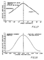
- a synthetic aperture is constructed with the length of the aperture determined by the number of elements which are summed together for a particular focus point. In the illustrated embodiment, ten elements have been chosen. However, it will be appreciated by those skilled in the art of ultrasonic imaging that the particular number of elements chosen is dependent on the beam profile of each transducer element XD N as illustrated in FIG. 17 and the depth of the focus points 138.
- the apodization value is computed as follows: First, a particular focus point 138 is selected and the number of elements to form the synthetic aperture is selected (ten in the illustrated embodiment). Second, a standard Hamming window for the synthetic aperture as illustrated in FIG. 18 is referenced. In the illustrated embodiment, the width of the ten transducer elements is approximately 0.7mm (see FIG. 18). Third, for each transducer element, the position within the Hamming window of FIG. 18 is determined. The normalized amplitude value is the desired apodization value. Fourth, the sensitivity of the element to the focus point is determined by the angle ⁇ from the surface of the transducer to the focus point 138. For example, if the value of the angle ⁇ in FIG.
- the transmission beam profile in FIG. 17 indicates that the normalized response amplitude is approximately .85. This beam profile corresponds to a natural apodization for the aperture.
- the raw weight assigned to each delay value is computed from the relationship: where i is 0 through 9 for the ten elements used for each focal point.
- the focus map information only needs to be computed for one octant of the focus area.
- the focus map information for the remaining octants may be determined from the information computed in the initial octant through very simple manipulations of the data that need not be detailed herein.
- the focus map information After the focus map information has been computer, it is stored in the focus map memory 116. This focus map information is utilized by the sequencer 118 to operate the cross-point switch 114 so as to select the proper 16-bit words from the appropriate ten transducer signals stored in the acoustic frame buffer 112 for application of the proper weighting factors W N at the multipliers 119.
- the conventional video RAMs or VRAMs (not shown) of the buffer have the desirable feature of operating like high-speed serial shift registers which can be configured to deliver a 16-bit word by simply having 16 VRAMs.
- An additional one-bit VRAM (not shown) is used to contain time sampling or clocking information and is designed to run synchronously with the output of the acoustic frame buffer 112 for each of the ten transducer elements involved in a beam reconstruction. This sampling information is the time delay portion of the focus map memory 116 and eliminates the need to store actual memory addresses.
- the re-sequencing of the signal data of the ten transducer elements with a timing signal is equivalent to providing a sequence of addresses which identify the proper 16-bit words in the memory sections 113 during reconstruction of a beam or vector 140.
- weighting factors W0-W9 they are also preferably implemented by VRAMs (not shown). There is one weighting factor W n for each transducer element XD N , each reconstruction vector, and each point on the reconstruction vector. Each weighting factor W n corresponds to one timing bit in the one-bit VRAM. Therefore, an 8-bit parallel VRAM arrangement, containing apodization values, is clocked by the timing information from the one-bit VRAM to provide to the multiplier 119 a sequence of corresponding weights W n at the appropriate times.
- each of the ten transducer channels from the cross-point switch 114 used to reconstruct a focus point 138 is not synchronous.
- the final output to the summer circuit 120 must be synchronous, however, and therefore each parallel channel from the cross-point switch 114 is first passed through a FIFO (not shown) to realign the data.
- the sequencer 118 is preferably a multi-PAL based hardware sequencer. It also optimizes the symmetrical aspects of the reconstruction according to the pre-computed focus map parameters.
- the sequencer 118 starts with the focus beam 140 at angle zero and sweeps around the 360 degree circle in 1756 steps as implied in FIG. 15.
- the sequencer 118 loads the appropriate VRAM shift registers for each of the nine element channels in focus range. The shift registers are then allowed to clock and data is re-sequenced according to the pre-computed focus parameters of the focus map memory 116.
- the sequencer 118 steps to the next focus beam and the process is repeated until all beams are done.
- each of the collective signals produced by the summer 120 corresponds to a value of one of the focus points 138 along the various focus beams 140.
- the values are produced sequentially with respect to the points 138 on the beams 140, such that a filtering process may be applied to the points along the beam.
- the information from the summer 120 is rectified and filtered in the digital rectification and filter 122 in FIG. 13b.
- the digital filter 122 is based upon FIR filter coefficient computations found in standard digital filter literature.
- the filter is a four-point FIR filter which symmetrical coefficients of [0.21,0.5,0.5,0.21] which has been found to be effective in producing the desired low-pass filter characteristics.
- the focus beams 140 comprising a plurality of focus points 138 have been formed through delays and weighting (in the cross-point switch 114 and multipliers 119), and have additionally been rectified and low-pass filtered (in filter 122) to result in beams containing discrete values which represent tissue information gathered from the received ultrasonic signals.
- filter 122 the attenuation of the reflected ultrasonic waves caused by the distance of travel through a medium is negligible. Therefore, there is no compensation for this type of attenuation in the preferred image reconstruction technique. However, distance attenuation may be dealt with in a digital manner in the focus map memory 116 if desired.
- the radial focus beams 140 After the radial focus beams 140 have been formed, they are mapped to a cartesian grid so the information may be presented on a standard video display 26.
- the X, Y pixel points 150 in FIGS. 15 and 16 comprising the cartesian grid must be filled with data from the focus points 138 on the beams 140.
- the angle-dependent sample rate converter 124 In order to fill the grid with focus points 138, the angle-dependent sample rate converter 124 first maps each of the focus points 138 either up or down so as to place them on the nearest vertical grid crossings as shown in FIG. 16. At this point, the vector data which is now referenced by a "Y" cartesian coordinate and an angle ⁇ , is converted to an 8-bit value since this is much more practical for modern display devices. This allows the various points to take on 256 different "gray" values for display, which is more then adequate for normal visual perception of the images.
- the resultant points then are stored in the Y, ⁇ memory buffer 126.
- each cartesian pixel point 150 is filled with information from the nearest point in the Y, ⁇ buffer as shown in FIG. 16.
- each cartesian pixel point 150 will contain an 8-bit value representative of the value of the nearest focus point 138 produced by the beam reconstruction.
- the pixel information is placed in the proper area of the pixel memory system 132 by the video system 130, and the information is then passed through a gamma correction lookup table 134 of known construction and a digital-to-analog converter 135 before it is displayed on the video monitor 26.
- a new ultrasonic imaging device is provided for imaging inside cavities whose small sizes have heretofore made such imaging impossible.
- the invention is intended to find most usefulness in medical diagnostic and therapeutic techniques.
- the precise nature of the imaging plane P may be subject to the problems addressed and any suggested solutions.
- the axes of the transducer elements may be angled with respect to the longitudinal axis of the probe in order to provide forward viewing in the cavity.
- Such forward viewing may be necessary if a laser device is used in connection with the invention. Forward viewing would allow the laser device to be guided using the visual aid of a real-time image of the target area as provided by the invention. It is anticipated that in such forward viewing applications, the apparatus and method of accumulating the imaging data and its processing remain essentially the same.
Abstract
Description
- The present invention relates to a device according to the preamble of
claim 1. - US-A-4,325,257 discloses a device of this type and more specifically involves a digital synthetic-focus, acoustic imaging system which is operative in real time and includes one or more electro-acoustic transducers arranged to receive broadband pulses from a pulse generator for excitation of acoustic pulses which are directed into the region under observation. Signals reflected from an object or discontinuity in the region are received by the same transducers, and after inverse filtering and nonlinear amplification are converted to digital signals. These digital signals are stored in separate high speed random access memory units for storage, but are subsequently time-equalized through use of a programmed focus memory unit prior to delivery to a digital adder and thence through a digital-to-analog converter for ultimate intensity modulation on a raster scanned display unit which provides the real time image.
- Generally, in the United States and many other countries, heart disease is the leading cause of death and disability. One particular kind of heart disease is atherosclerosis, which involves the deposition of fatty material on the inside of vessel walls throughout the body (commonly called "plaque"). As the plaque collects, the artery narrows and blood flow is restricted. If the artery narrows too much, the heart muscle nourished by the artery receives insufficient oxygen and a myocardial infarction or "heart attack" can occur. Atherosclerosis can occur throughout the human body, however, it is most life threatening within the coronary vasculature.
- Physicians have a wide range of tools at their disposal to treat patients with coronary artery disease. Coronary artery bypass grafts or "open heart" surgery can be performed to bypass blocked artery segments. Other, less invasive procedures are available. For example, some blockages may be dissolved by chemical treatment. Alternatively, a procedure known as percutaneous transluminal coronary angioplasty (hereinafter "PTCA") may be performed in which a catheter with an expandable section on its end is placed within the narrowed artery and inflated to compact the plaque against the vessel wall, thereby relieving the blockage.
- No matter what method is used to treat coronary artery disease, it is necessary for physicians to obtain quantitative information on the condition of the vasculature within the heart. Traditionally, coronary angiography has been the method of choice. Coronary angiography involves the placement of the end of a catheter at the beginning of the coronary vasculature. A small amount of radiopaque dye is injected, and a X-ray motion picture is taken while the dye is pumped through the vessels. The physician then examines the pictures and looks for any telltale narrowing of the blood flow opacified by the radiopaque dye. By the number and degree of such narrowing, the course of treatment can be determined.
- Angiography has the extreme limitation of indicating only where the blood is within the vessel; it reveals nothing of the condition of the inside of the vessel and the vessel wall itself. Furthermore, most angiography machines present virtually only one-dimensional projections of where blood flow exists. Because of this imaging limitation, the complex structures within the coronary vascular often exhibit quite ambiguous images.
- Recently, imaging of soft tissue such as gross cardiac structures has provided physicians with diagnostic images having quality that is unavailable from conventional techniques using X-ray radiation. In particular, magnetic resonance imaging (MRI) and ultrasound have become important diagnostic tools for cardiac assessment. Although MRI has the ability to image blood vessels, the image resolution is not sufficient to allow assessment of the condition of the walls of the vessel. Conventional ultrasound scanning also suffers from lack of resolution. More recently, high frequency (hence, high resolution) ultrasound has been used during open heart surgery to access the coronary arteries. This method requires the opening of the chest cavity to expose the heart surface and is hence limited in its application.
- In an even more recent development, in vivo ultrasonic imaging of the human body creates the potential for access to a wealth of information regarding the condition of a patient's vasculature that is currently only at best indirectly available from other sources. The information received from in vivo imaging may be used as a diagnostic tool to help determine patient treatment, or as a surgical tool, supplementing angiography in PCTA.
- In vivo ultrasonic imaging from within the heart has been described in US-A-3,938,502. In order to provide for ultrasonic imaging inside the human body, this patent provides an array of small transducer elements which may be introduced into the body by way of catherization. The array of elements is excited at ultrasonic frequencies and the reflections or echos of the generated ultrasonic acoustic waves are detected by the piezoelectric properties of the transducers. Unfortunately, due to the nature of the material used for the transducers, the array of elements cannot be made small enough to allow passage into small areas such as the coronary arteries. Therefore, use of the known device is limited to within the heart chambers and the associated great arteries.
- An additional limitation of the known device is the poor resolution caused by a sparse distribution of transducer elements. Piezoeletric materials of the type used according to the cited patent (e.g., ceramics) have a practical limitation in size reduction. Because of this size limitation and the fact that the maximum resolution of the transducer array is limited by the center-to-center spacing of adjacent elements, the known device is inherently limited in the quality of its image resolution.
- A further limitation of the known device is the fixed delays it provides for focusing an image. Such fixed delays do not provide satisfactory images for identification of tissue structures. For a satisfactory image, a dynamic focusing feature is needed to provide an optimal focus at a plurality of points in the imaging plane. One approach to implementing such a dynamic focusing feature is a so-called "synthetic focus" or "synthetic-aperture" approach disclosed in above reference US-A-4,325,257.
- An ultrasonic imaging device similar to the device disclosed in above cited US-A-3,938,502 is further disclosed in US-A-4,576,177. More specifically, this document relates to an apparatus and method for identifying and removing arteriosclerotic plaque deposits from blood vessels. The known apparatus comprises a catheter having an optical fiber for transmitting laser irradiation and an ultrasonic transducer mounted at the tip of the catheter for transmitting and receiving ultrasonic signals. The apparatus further comprises a transmitting unit for generating electrical impulses for activating the ultrasonic transducer, a receiving unit for displaying electrical signals from the ultrasonic transducer and a laser. Arteriosclerotic plaque deposits are identified by the ultrasonic echoes which result from transmitted ultrasonic signals and are removed by laser irradiation.
- For many diagnostic and therapeutic purposes, in vivo ultrasonic imaging must simulate real-time performance. To achieve diagnostic or therapeutic quality images in small cavities while maintaining real-time performance is a formidable task and one which applicants believe has not previously been attained.
- It is a general object of the invention to provide diagnostic quality, virtual real-time ultrasonic images of small cavities and their associated surrounding structures from within the cavities.
- This object according to the present invention is accomplished by means of a device including the features of both the preamble portion and the characterizing clause of
claim 1. - It is an advantage of the invention that it provides a device of providing diagnostic quality, virtual real-time ultrasonic images that is sufficiently flexible to accommodate a range of ultrasonic imaging requirements from within small cavities.
- It is a further advantage of the invention that it provides an array of transducer elements for generating ultrasonic imaging data that is small enough to enter small cavities, yet also exhibit controlled behavior and is manufacturable on a commercial basis. In this connection, it is a related advantage of the present invention that it maintains a high degree of sensitivity to signals from weak reflectors of ultrasonic signals, such as human vascular tissues, while maintaining the small size of the array of transducers.
- It is another advantage of the invention that it provides the physician with the ability to accurately position the array of transducers within the imaging area.
- It is yet another advantage of the invention that it minimizes the number of wires required to connect the in vivo portion of the ultrasonic imaging device of the invention to an in vitro processing stage. In this connection, it is a related advantage of the invention that it distributes the control of the excitation of the array of transducer elements between in vivo and in vitro sites.
- It is still another advantage of the invention that it electrically isolates the in vivo portion of the imaging device of the invention in order that it is safe for use in human imaging applications. In this connection, it is a related advantage of the invention that it provides operation of the imaging device without causing significant risk to humans from excessive localized heating or radiation.
- A still further advantage of the present invention is its operation at very low power dissipation in vivo in order to prevent heating of surrounding tissue and expansion of parts.
- It is a further advantage of the present invention that it provides an imaging device whose in vivo portion may be mounted to a positioning device such as a catheter, which allows the use of, for example, conventional guiding catheters and guidewires. In this connection, it is a related advantage of the present invention that the imaging device is suitable for incorporation into recent catheter systems, and allowing for the continued use of, for example, guiding catheters and guidewires, in conjunction with catheter-based diagnostic and therapeutic procedures such as angioplasty, regional therapy for dissolving plaque and the like.
- It is a more detailed advantage of the invention that it provides an in vivo imaging device for producing real-time images of small, moving or stationary cavities and surrounding tissue structure that is uniquely and advantageously constructed using a conventional catheter assembly fitted at its end with a probe assembly for transmitting and receiving ultrasonic signals from elements of an array of ultrasonic transducers incorporated into the probe assembly. The transducer elements are selected and controlled by an in vitro electronic signal processing and imaging unit which transmits excitation and control signals via a transmission cable to integrated circuitry on-board the body of the probe assembly. The integrated circuitry routes excitation signals to the transducer elements in a predetermined sequence. The body of the probe assembly not only supports the array of transducer elements and the integrated circuitry, but also accommodates conventional catheter devices such as a catheter guidewire that may be threaded through the probe assembly.
- The number of wires in the transmission cable connecting the integrated circuitry to the processing and imaging unit are minimized by providing for a multiplexing task at the integrated circuitry on-board the probe assembly. Due to the relatively few number of conductors comprising the transmission cable, there is a high degree of physical flexibility achieved, and there is a relatively small cross-section obtained, which makes the device convenient for use within the limited confines of its intended operating environment. The integrated circuits also buffer excitation signals from the transmission cable which are directed to a selected element in accordance with a preferred image reconstruction scheme. These pulses are converted into ultrasonic waves by the transducer elements. The echoes or reflections from the environment are received by the transducer elements, converted back into electrical signals which are relatively weak, and buffered by the integrated circuits so that the weak signals are boosted before being directed onto the transmission cable for delivery to the signal processing and imaging unit.
- Because of the very small size of the probe assembly, the piezoelectric material used for the array of transducer elements is preferably continuous in order to simplify construction of the probe. Further, the material may be characterized by a high internal electrical impedance resulting in weak electrical output current in response to ultrasonic echos. In order to provide a wide beam pattern as desired by the preferred imaging technique, the transducer elements adjacent an element or elements receiving an excitation signal are shunted to a low impedance to confine the active region to the selected transducer or transducers.
- Within the electronic signal processing and imaging unit, signals indicative of the reflections or echos of ultrasonic acoustic waves are processed at extremely high speeds such that signal digitization and dynamic digital signal averaging, with respect to each individual or group of transducer elements, may be implemented, thereby producing resultant signals having a very high dynamic range. These resultant signals are then processed into diagnostic information in the form of, for example, images. The signals are preferably processed using a synthetic-aperture approach wherein dynamic time delays and weighting factors are used to produce a myriad of individually focused points throughout the entire image plane, thereby resulting in real-time, high resolution diagnostic images of the cavity and surrounding structure.
- Other objects and advantages of the invention will be apparent from the following detailed description and the accompanying drawings, in which:
- FIGURE 1 is a system-type diagram of the ultrasonic imaging device of the invention, illustrating the use of the device to image a coronary artery during a PTCA procedure;
- FIG. 2 is an enlarged and partially sectioned view of a portion of the coronary artery in FIGURE 1, showing the probe assembly of the ultrasonic imaging device of the invention located at the tip of the catheter approaching an area of plaque buildup in the artery and the equivalent histologic view of the same to a surgeon;
- FIG. 3 is the same view as illustrated in FIG. 2, except the catheter has been further drawn into the area of plaque buildup in the coronary artery so as to bring a balloon section of the catheter into the area, where the balloon is inflated in order to compress the plaque in accordance with a standard PTCA procedure;
- FIG. 4 is the same view as illustrated in FIGS. 2 and 3, except the catheter has been repositioned so that the probe assembly of the ultrasonic imaging device is in the area of the plaque buildup, and it is providing the surgeon with an image of the cross-sectional area of the coronary artery that can be used to determine how well the PTCA procedure opened the artery for additional blood flow;
- FIG. 5 is a cross-sectional view of the tip of the catheter in FIGS. 2-5, illustrating the probe assembly of the ultrasonic imaging device of the invention housed in the tip of the catheter and adjacent to its balloon section;
- FIG. 6 is perspective view of the probe assembly of FIGS. 2-5 with the sheath and epoxy encapsulation covering the probe assembly removed to expose the underlying electronics and associated construction;
- FIG. 7 is cross-sectional view of the probe assembly taken along the line 7-7 in FIG. 6;
- FIG. 8 is a side view of the probe assembly with a portion cut away to expose the composition of the body of the assembly along its longitudinal axis;
- FIG. 9 is a graph illustrating an exemplary frequency spectrum echo response for one of the transducer elements defined by a conductive trace on the probe assembly and an overlying portion of a band of a piezoelectric polymer, where the abscissa is the frequency of the acoustic waves impinging on the transducer element measured in Megahertz and the ordinate is the electrical response of the piezoelectric polymer measured in microamps;
- FIG. 10 is a graph similar to that of FIG. 9, except the frequency response of the transducer element is measured after it has been converted by a transimpedance amplifier configuration incorporated in integrated circuitry on-board the probe assembly, where the abscissa is still measured in megahertz but in ordinate is not measured in volts;
- FIG. 11 is a schematic block diagram of the electronic circuitry contained in each of the plurality of chips mounted to a carrier portion of the probe assembly;
- FIG. 12 is a detailed component diagram of a delay buffer which provides important timing signals in the electronic circuitry of FIG. 11;
- FIGS. 13a and 13b illustrate a schematic block diagram of the in vitro processing and imaging unit of the ultrasonic imaging device according to an exemplary embodiment of the invention;
- FIG. 14 is a diagrammatic representation of a portion of the array of acoustic transducers and one of a plurality of radial focus beams, each having a plurality of focus points for reconstructing an image derived from partial vectors associated with the ultrasonic signals received by the transducers;
- FIG. 15 is a schematic illustration of the screen of a video display used to generate the images shown in FIGS. 2 and 4, showing how the plurality of radial focus beams are mapped onto the pixels of the screen; and
- FIG. 16 is an enlarged and partial view of the schematic in FIG. 15, illustrating how the points comprising the focus beams are matched with the pixels of the video display screen;
- FIG. 17 is a graph in Cartesian coordinates of an exemplary beam profile for each element in the transducer array, where the normalized amplitude as plotted on the ordinate is measured at a constant radius and the beam angle plotted on the abscissa is measured from the center of the cylinder formed by the array;
- FIG. 18 is a graph in Cartesian coordinates of the Hamming window profile for a single element in the transducer array, where the normalized amplitude is plotted on the ordinate and a circumferential distance from a central radial beam is plotted on the abscissa.
- While the invention will be described in connection with angioplasty or PTCA surgery, it will be understood that it is not intended to be limited to such use. On the contrary, the invention is intended to cover all applications which may require imaging in a small cavity. An example of such an alternative application is the use of the invention on the end of a catheter without the incorporation of a balloon. A specific example of such a use is a pharmaceutically therapeutic use where cholesterol-inhibiting drugs are used for regional therapy and the imaging device of the invention is used to monitor the effectiveness of the drugs in removing plaque. Another specific example of an alternative use in a physical therapeutic use such as measuring blood flow rates (using Dopler sound imaging in conjunction with invention) or determining sizes and locations of gall stones and the like. Yet another example of an alternative application is the incorporation of the invention into a catheter in conjunction with a laser or like devices for burning plaque in the arteries.
- Turning to the illustrated embodiment and referring first to FIGS. 1-4, a buildup of fatty material or
plaque 12 in acoronary artery 14 of aheart 16 may be treated in certain situations by inserting aballoon 18, in a deflated state, into the artery via acatheter assembly 20. As illustrated in FIGURE 1, thecatheter assembly 20 is a three-part assembly, having aguide wire 19, a guide catheter 20a for threading through the large arteries such as the aorta 22 and asmaller diameter catheter 20b that fits inside the guide catheter. After a surgeon directs theguide catheter 20 and theguide wire 19 through a large artery leading to the aorta 22, thesmaller catheter 20b is inserted. At the beginning of thecoronary artery 14 that is partially blocked by thefatty material 12, the guide wire is first extended into the artery, followed bycatheter 20b, which includes theballoon 18 at its tip. - Once the
balloon 18 has entered thecoronary artery 14, an ultrasonic imaging device including aprobe assembly 24 housed in the tip of thecatheter 20b provides a surgeon with a cross-sectional view of the artery on avideo display 26. Signals from theprobe assembly 24, indicative of reflected ultrasonic waves, are transferred along acable 28 to asignal processor 30 located outside the patient. Thecatheter 20b ends in a three-port junction 29 of conventional construction that couples the catheter to aninflation source 31, a guide wire source and thesignal processor 30. The inflation and guidewire ports 29a and 29b, respectively, are of conventional PTCA catheter construction. The third port 29c provides a path for thecable 28 to connect with thesignal processor 30 andvideo display 26 via an electronic connector 33. - A previously noted, the invention is not intended to be limited to a PTCA environment. In this regard, it will be appreciated that for use of the invention in a regional therapy application where cholesterol-inhibiting drugs are used, the
port 29a may be an injection site for the drug instead of an inflation source and, of course, theballoon 18 at the end of thecatheter 20b is not needed. - Returning to a discussion of the invention in a PTCA application, the imaging device provides an
image 32 on thedisplay 26 that indicates when theballoon 18 is within a partially blocked area of thecoronary artery 14 as is best seen in FIGS. 2-4. After locating the partially blocked area, the tip of the catheter 20a containing theprobe assembly 24 is moved past the blocked area in order to bring the followingballoon 18 into the area as shown in FIG. 3. Theballoon 18 is thereafter inflated so as to compress theplaque 12 causing the blockage. Finally, the cardiologist may check the results of the PTCA procedure, by slightly withdrawing the catheter 20a in order to bring the tip and the associatedprobe assembly 24 back into the blocked area as shown in FIG. 4. If the PTCA procedure was successful, theimage 32 on thevideo display screen 26 will show the lumen of theartery 14 has increased in cross-sectional area. - In practice, the
probe assembly 24 is constructed to be sufficiently small to fit in cavities of approximately the size of a human coronary artery as shown in the illustrated embodiment. In order to provide for such small size, applicants have provided a unique and innovative construction for theprobe assembly 24. First, a polymer piezoelectric material is used to provide transducer elements for generating and receiving ultrasonic acoustical waves. Preferably, the polymer piezoelectric material is continuous in order to provide for ease of manufacture. In the illustrated embodiment, the piezoelectric material forms aring 44 for viewing in a plane P (FIG. 5) passing through the material and normal to its surface; however, it will be appreciated that in other applications or for viewing in alternative planes, the piezoelectric material may take other forms. To obtain good performance from the polymer piezoelectric material, it is necessary that the natural frequency of the material be much higher than the chosen operating frequency. In the illustrated embodiment, a frequency of 20MHz is chosen as the operating frequency. - Not all piezoelectric polymers are suitable for use as the
ring 44. An acceptable material must have the following characteristics. The material must, of course, have good sensitivity characteristics for detecting reflected ultrasonic waves. Because of the small size and cylindrical shape of thering 44, however, the piezoelectric material must also be capable of being formed into a suitable shape of very small diameter (e.g., a cylinder of about 1.5mm. diameter). For example, the material may start as a flexible sheet or, if it is not flexible, it may be formed directly into the desired shaped by deposition or other well-known forming processes. Also, because the material is continuous, it must be characterized by good acoustic behavior. In other words, excitation of one element in the array formed by thering 44 must not generate shear waves or ringing from interaction with other elements in the array. As explained more fully hereinafter, the invention includes electronics that aid in eliminating shear waves or ringing. Furthermore, the piezoelectric material must be well matched to the human tissue immediately surrounding theprobe assembly 24. For the foregoing criteria, applicants are presently employing the copolymer P(VDF-TrFE), having a thickness of approximately nine (9) microns. Other, alternative materials are PVDF, copolymer P(VDF-TFE), composites of polymers and ceramics (e.g., PZT), or a depositable material such as ZnO. - Because of the small size of the
probe assembly 24, it will also be appreciated that acontinuous ring 44 of material is much more preferable than an individual piece of piezoelectric material for each transducer element. The manufacturing complexities avoided and the cost savings obtained are considerable if a continuous ring of piezoelectric material is used. For example, using a continuous material, there is no need to cut individual elements. Cutting individual elements of the very small size requiring for theprobe body 42 would be very difficult and expensive. - Of course, the piezoelectric polymer
material comprising ring 44 must be supported, and thebody 42 serves the purpose. Since acoustic energy is reflected at interfaces between regions of differing acoustic impedance, a hard backing for the transducer array is necessary to ensure that most of the ultrasonic energy is not absorbed by the backing. In the preferred embodiment, an alumina composition (i.e., Al₂O₃) of thebody 42 provides the necessary hard backing. - As best seen in FIG. 6, the
body 42 of theprobe assembly 24 has box-shaped and cylindrically-shaped sections 42a, 42b, respectively. A third transitional section 42c joins the other two sections 42a, 42b by tapering thebody 42 along its axial length from the cylindrical section to the box-shaped section. In order that theprobe assembly 24 is sufficiently small to fit inside areas such as thecoronary artery 14, it preferably has the following approximate dimensions: Diameter of cylindrical section 42b -- 1.5 millimeters; width of one side of box-shaped section 42a -- 3/4 millimeter; axial length -- 3.0 millimeters; diameter ofaxial bore 40 -- 1/2 millimeter. - The
body 42 is formed by known injection molding techniques. Because the dimensions of thebody 42 are small and the tolerances are small (e.g., the tolerance on the outer diameter of the cylindrically-shaped section 42b is 1.22 microns (500 microinches)), very precise machining is required for the injection mold. Furthermore, the small size of thebody 42 makes it impractical to polish after molding. Therefore, it is important that the injection molding process provides a smooth surface. - It is an important feature of the invention that the
body 42 of the probe assembly not interface with conventional PTCA, regional drug therapy and other therapeutic or diagnostic procedures that utilize catheters and may advantageously incorporate the invention in order to improve those procedures. Therefore, in order to secure theprobe assembly 24 to the tip of thecatheter 20b, a conventional guide wire lumen inside the catheter is telescopically fitted over a matingguide wire lumen 38 forming thecentral bore 40 in the probe assembly as best seen in FIG. 5. To further secure theprobe assembly 24, the end of thecatheter 20b is joined to the probe assembly by way of an epoxy material 41 encapsulating and protecting theintegrated circuits 54 mounted on the rectangular section of the body. By joining theprobe assembly 24 to thecatheter 20b in the foregoing manner, the ability of thecatheter 20b to perform a conventional catheterization procedure is uneffected, since thebore 40 allows the guide wire to exit the tip of theprobe assembly 24. To guard against possible contamination of blood caused by accidental contact of blood with the materials of thebody 42, thebore 40 is lined with, for example, kapton. To further protect against contamination (and possible electrical shock), the outside of theprobe assembly 24 is covered by a protective sheath (not shown) made of, for example, parylene. - As is well known in PTCA procedures, the
catheter 20b supports theballoon 18 at its one end. In the preferred embodiment, theballoon 18 is positioned adjacent theprobe assembly 24 and is isolated from ambient conditions by sealing the two ends of the balloon to the catheter in a conventional manner. The area of thecatheter 20b covered by theballoon 18 includes a series ofholes 43 for communicating fluid between the balloon and aninflation source 31 in FIG. 1. - Each wire in the
cable 28 is formed of conventional "magnet" wire -- i.e., a solid conductor protected by an insulating coating. Over the bundle of wires, a ribbon of copper (not shown) is spiraled in order to provide a ground shield for the signals carried by thecable 28. Preferably, the copper ribbon is provided with a protective insulating coating. - To provide an array of tranducer elements for generating imaging data, a plurality of underlying
conductive traces 46 are formed on the surface of the cylindrical section 42b of thebody 42 and underlie thering 44 of continuous piezoelectric material. In order to provide a ground plane for the transducer array, the outer surface of thering 44 of piezoelectric material has a thin coating of metallic material. Each element of the array is defined by an area of thering 44 overlapping the conductive traces as generally indicated in FIG. 7. In order to maintain thering 44 of piezoelectric material at a fixed position over the conductive traces 46, a film of an epoxy glue holds the inner surface of the ring of material to the surface of theprobe body 24. Thering 44 may be formed of the piezoelectric material as a cylinder or it may be a flat sheet that is rolled and joined at a seam. Preferably, thering 44 is a seamless cylinder. The conductive traces 46 are evenly spaced about the circumference of section 42c of thebody 42. Such a construction results in the elements of the array being aligned with their length axes parallel to the length axis of thebody 42. Preferably, there are 64conductive traces 46 and, therefore, 64 transducer elements. - To form the three-dimensional conductive pattern on the
body 42 that includes thetraces 46 defining the transducer elements and connections for the onboardintegrated circuit chips 54, the body is first coated with a well-known titanium and tungsten mixture, using conventional deposition techniques. Over the titanium and tungsten mixture, a layer of gold is deposited onto thebody 42. To etch the conductive pattern, thebody 42 is held in a jig (not shown) and state-of-the-art laser oblation methods are used to etch the pattern on each side of the box-shaped section 42a, proceeding one side at a time. For the cylindrically-shaped and transitional sections 42b and 42c, respectively, each is etched separately by incrementally rotating the body in the jig. - In addition to not absorbing significant amounts of ultrasonic energy, the
body 42 must not have resonant effects due to the energy reverberating in the cylindrically-shaped section 42b that are within the frequency region of operation. Such reverberation is evidenced by a notch in the frequency response of each element in the array. The frequency position of the notch is controlled by keeping the alumina under the transducer thin. In particular, the cylindrical section 42b of theprobe body 42 is recessed so that the body defines a thin annular wall 48 for supporting thering 44 of piezoelectric material. - Referring the FIG. 9, the frequency response spectrum of the
ring 44 of piezoelectric material includes a notch N whose frequency position in the spectrum is effected by the following factors: (1) the thickness or the wall 48, and (2) the acoustic velocity of the sound within the material comprising the wall. By controlling the thickness of the wall 48, the notch N is positioned outside the frequency region of the transducer array (e.g., 15-25MHz). - Quantitatively, the annular wall 48 has a thickness d as illustrated in FIG. 8 and destructive interference forming the notch N in FIG. 9 occurs when the half-
wavelength 
thickness d. 

where n is an odd integer - i.e., 1, 3, 5, etc. - In order to ensure all the notches in the frequency response of the piezoelectric material occurs at a frequency above the bandpass frequency of the system, the first notch (N in FIG. 9) should be at no lower a frequency than, for example, 28MHz. Knowing the velocity V of the ultrasound waves through the alumina, equation (1) can be rewritten as


Therefore, the thickness of the annular wall 48 should be .182 mm or less. In order to fill therecess 50 formed by the annular wall 48 without significantly effecting the acoustic properties of the probe body, anacoustic backing material 52 such as urethane is used. - In accordance with one important aspect of the invention, because small piezoelectric transducers made from copolymers such as P(VDF-TrFE) are characterized by very high electrical impedance values (e.g., 30K ohms for one element), very low current signal levels are generated by each array element in response to reflected acoustic waves. In order to ensure these low current signals are not lost, and a high voltage signal is delivered to the
signal processor 30, transimpedance amplifiers are located on-board theprobe assembly 24 and in close physical proximity to thering 44 of piezoelectric material. Preferably, the amplifiers provide current-to-voltage amplification in a linear relationship where one microamp produces approximately 750 microvolts. To provide these transimpedance amplifiers, theprobe assembly 24 includes a plurality of the integrated circuit chips 54 (four in the preferred embodiment). Eachchip 54 includes current amplifiers as discussed in greater detail in connection with FIG. 11 that receive low current signals from the high impedance transducer elements and provide the low impedance (e.g., 50 ohms)cable 28 with a high voltage signal. Although the actual amplifier devices for each channel are current amplifiers with an approximate gain of 15 from transducer element to cable, the overall effect of the amplifiers is one of transimpedance since the signal is received from a high impedance current source (the element) and delivered to a lower impedance load as a voltage (the cable and its termination). FIG. 10 illustrates the frequency response of an element in the transducer array with the transimpedance amplifier and additional voltage amplification. - In order to physically fit the
integrated circuit chips 54 onto thebody 42 of theprobe assembly 24, the fourintegrated circuit chips 54 are of an inverted chip design and are bonded toconductive pads 56 formed on the box-shaped section 42a of the probe body. Thepads 56 interconnect each of the fourchips 54 and also provide a connection betwen the chips and thecable 28 within the catheter 20a that connects the chips to thesignal processor 30 outside of the patient. In order to provide communication between theconductive strips 46 which form the transducer elements and thechips 54, the strips extend along the axial length of theprobe 24, beyond thering 44 of piezoelectric material and down the transitional section 42c toconductors 58 on the underside of thechips 54. - In accordance with another important aspect of the invention, the
cable 28 from thesignal processor 30 provides communication channels between the processor and theintegrated circuits 54, using a minimum number of wires. The fourintegrated circuit chips 54 provide a multiplexing function that distributes excitation pulses from thesignal processor 30 to a predetermined one or ones of the transducer elements. In the preferred embodiment, a single pair of wires T+, T- in the cable carry the excitation signals as differential pulses in series format from thesignal processor 30 to thechips 54. At thechips 54, each excitation signal is routed to an appropriate one of the transducer elements in order to execute an excitation sequence used by the preferred image reconstruction technique. By minimizing the number of wires required to carry the excitation signals to each of the transducer elements (e.g., 64 in number), not only is the problem of fitting a bulky cable incatheter 20b overcome, but also overcome is the problem of providing more than 64 contacts on the surface of the verysmall body 42. - Each
chip 54 as illustrated in FIG. 11 has 16channels 60 associated with 16 of the 64 transducer elements XD₁ - XD₆₄ defined by thering 44 of piezoelectric material and the conductive traces 46. Eachchip 54 is responsible for sequentially transmitting and receiving ultrasonic signals on one of its associated 16 channels. At any given time, exactly one of thechips 54 will be designated as active, where "active" indicates the onechip 54 that is currently exciting one of its associated transducer elements XDN. Furthermore, at any given time only one of the 16channels 60 on anactive chip 54 is free to be excited by an excitation signal or to receive reflections or echos. The electrical signals generated from the reflections impinging on the free transducer element are amplified and sent via thetransmission cable line 28, to the externally locatedsignal processor 30 as explained more fully hereinafter. - Each excitation signal intended for one of the transducer elements XDN travels down the transmission lines T+, T- as a differential pulse. Preferably, the excitation signal consists of two closely spaced short duration (of approximately 25 nanoseconds) pulses. An excitation signal of this form generally provides significantly more transmitted acoustic energy from an excited transducer than would a single pulse. By empirical methods, an optimization is realized between maximizing the transmitted acoustic amplitude and maintaining reasonable image resolution. Furthermore, since the control of this pulsed excitation signal is accomplished externally at the
signal processor 30 through the T+ and T-transmission cable lines 28, the particular form of this signal can be modified to maximize the desired features of the signal. - At the
master chip 54, this differential pulse is received and amplified by the differential pulse receiver amplifier 62 as shown in FIG. 11. By transmitting the excitation signal as a differential pulse, the signal is substantially immune from the problems of electromagnetic interference. Preferably, the differential pulse is supplied to the T+ and T-transmission cable lines 28 via an analog buffer (not shown) which converts a received unipolar excitation signal from thesignal processor 30 into the desired differential pulse. - To distribute the excitation signals to the correct one of the 64 channels, only one of the
chips 54 receives timing signals on lines CDATA and CCLK and an excitation signal on line T+,T- from thetransmission cable 28, although all four of the chips are capable of receiving these signals because of their identical structure. This onechip 54 receiving timing and excitation signals cooperates with the other three chips in a master-slave relationship where the signal lines CDATA, CCLK and T+,T- are used to generate a system clock (i.e., SYS CLK) for synchronizing all fourchips 54, and to distribute the excitation signal T+,T- by way of lineSYSTRAN . - In order to provide communication between all of the
chips 54, bus lines are common to all the chips and are connected between adjacent chips byextensions 56a ofconductive pads 56, which are formed around the box-shaped section 42a of the body 42 (FIGS. 6 and 8). The bus comprises lines IREF,SYSTRAN , ANA OUT, SYS CLK, V+ and V-. In order to best describe the operation of the fourchips 54, the schematic diagram of one of the chips in FIG. 11 will be treated as the master chip which receives the signal lines CDATA, CCLK, T+,T- and V+, V- from thetransmission cable 28. - The
SYSTRAN line delivers the excitation signals to all thechips 54, and as will be described in more detail later, other signals are used to control the application of the excitation signals to the 64 transducer elements XD₁ - XD₆₄. (FIG. 11 shows 16 elements on one of four chips for a total of 64). In order to generate an excitation signal on theSYSTRAN line, a receiver amplifier 62 on thechip 54 receives the excitation signal in its differential pulse form and converts it to a unipolar form. From the receiver amplifier 62, the excitation signal is passed through an invertingbuffer 64 which supplies an inverted version of the excitation signal to all the chips through the commonSYSTRAN line. - In order to generate the signal on the common line IREF, the
master chip 54 responds to external bias currents on lines T+, T- by generating a cable bias current ICABLE BIAS which is used as a bias reference signal for indicating whichchip 54 is the master chip receiving the timing and excitation signals. From the cable bias current ICABLE BIAS, the reference current IREF is generated and distributed to all thechips 54 for producing the necessary bias voltages on the other chips. Specifically, the current IREF is generated at the drain of MOSFET 66 in the transistorcurrent mirror 64, 66 on themaster chip 54. The reference current IREF is used bybias generators 70, 72 to produce bias voltages for adelay buffer 74 and the individual channel amplifiers 60b which are discussed more fully hereinafter. - The cable bias current ICABLE BIAS is generated by a current mirror transistor configuration comprising two p-
channel MOSFET transistors 64, 66 with their gates connected in common, and their sources connected to a positive supply voltage V+, as shown in FIG. 11. The gate of one MOSFET transistor is also connected to its drain which in turn is connected to the T+ and T- lines ofcable 28. The voltage of the T+ and T- transmission cable lines of themaster chip 54 are held at a voltage lower than the positive supply voltage V+, and as a result of this lower voltage, the cable bias current ICABLE BIAS flows from the common gate and drain connection of thetransistor 64 located on themaster chip 54. - In order to distinguish the
master chip 54 from the other chips, the cable bias current ICABLE BIAS is utilized to assert a "M" line on themaster chip 54. By contrast, theother chips 54 will have no cable bias current flowing, due to the absence of the T+ and T- transmission cable connections, and will have a negated "M" line. Specifically, for eachchip 54 to determine if it is the master chip and either negate or assert its "M" line, a comparator 68 is used to compare the voltage level of the cable bias current on the line ICABLE BIAS to a predetermined comparator reference voltage VR1 derived from series resistors R₁ and R₂. For thechips 54 not connected to the T+ and T- transmission cable lines, the line for a cable bias current ICABLE BIAS remains at the supply voltage V+ which is greater than the reference voltage VR1, thereby causing the comparator 68 to negate the "M" line which designates the chip as a slave chip. Otherwise, if the T+ and T- transmission lines of thecable 28 are connected, there will be a voltage drop on the ICABLE BIAS line. This reduced voltage level will be lower in magnitude than the comparator reference voltage VR1, thereby causing the comparator 68 to activate the "M" line which designates the chip as the master chip. - From the foregoing description, it will be appreciated that only one of the four
chips 54 is designated as the master chip and accordingly only the master chip has an asserted "M" line, due to the presence of the T+ and T- connections fromcable 28. The other threechips 54 have negated "M" line, due to the absence of a connection to the T+ and T-lines and are therefore slave chips in the sense that they are controlled by way of the master chip. As discussed more fully hereinafter, the state of the "M" line is used in other areas of the chip circuitry to determine whether or not aparticular chip 54 is the master chip. - Timing signals received by the CDATA and CCLK lines are also dependent upon reference voltages generated by the current IREF or ICURRENT BIAS. For example, on the
master chip 54, the signal on the CDATA line is input to anamplifier 76 along with a reference voltage VR2 generated at the node connecting resistors R3 and R4 from the ICABLE BIAS circuitry. Thisinput amplifier 76 insures the proper voltage levels on thechip 54. The output of thisinput amplifier 76 is sent to an invertingbuffer 78 that acts as a transmission gate which is controlled by the state of the "M" line. As for the CCLK transmission line fromcable 28, it is connected through aninput amplifier 80 along with the aforementioned reference voltage VR2. The output ofamplifier 80 is sent to a non-invertingtransmission gate buffer 82, which in turn produces the clock signal SYS CLK on the common bus line for distribution to all thechips 54. This clock signal SYS CLK is used to sequence theshift register 84 on eachchip 54 in order to sequentially activate the 64channels 60 on theprobe assembly 24 as explained more fully hereinafter. - Turning to a detailed discussion of the excitation of the 64 transducer elements, the sequential stepping through the 16
channels 60 on each of thechips 54 is accomplished by shifting a single logic bit through the 16bit shift register 84. The logic outputs of theshift register 84 of aninactive chip 54 are all negated. Therefore, at any given time exactly one of the 16 outputs of theshift register 84 on one of thechips 54 is "active" and all the other 63 outputs are disabled. The CLK input to theshift register 84, driven by the SYS CLK bus line, allows the logic bit to be sequenced from one output QN to the next QN+1. Each of the output lines QN of theshift register 84 is used to sequentially and individually enable thetransducer channels 60 on thechip 54 by way of a NAND gate 60a and an enable input to the correponding channel amplifier 60b. As indicated in FIG. 11, there is a none-to-one correspondence between the individual outputs QN of theshift register 84 and theindividual transducer channels 60. For example, output Q₁ is associated withchannel 1, output Q₂ is associated withchannel 2, etc. - A separate chip select signal
CS is asserted by the one of the fourchips 54 that is currently activating one of itschannels 60 for the generation and detection of ultrasonic acoustic signals. At this time, chip select linesCS of the other threechips 54 are negated. TheCS signal is asserted by using one clocked SR flip-flop 88 and one unclocked SR flip-flop 90 as explained more fully hereinafter. - Two
bias generator amplifiers 70, 72 on eachchip 54 are responsible for producing the desired bias voltages needed for the operation of each chip. Thefirst bias generator 70 receives as an input the common reference current IREF which is generated on themaster chip 54, and utilizes this signal to produce the desired bias voltage on a BUF BIAS line for thedelay buffer 74. Since the presence of a bias voltage on the BUF BIAS line is only needed for aparticular chip 54 when one of itschannels 60 is active, theCS (inverted chip select) line is used to selectively activate and de-activate thebias generator 70. The second bias generator 72 is used to provide the proper bias voltage on a AMP BIAS line for the transducer channel amplifiers 60b. The second bias generator 72 is selectively activated and de-activated by the logical ORing of the CHIP TRANS line (an invertedSYSTRAN line) and a WAIT line from thedealy buffer 74 atOR gate 73. In order that a channel amplifier 60b transmits only signals from reflected acoustic waves impinging on the associated transducer element, the amplifier if activated only after achannel 60 has generated ultrasonic acoustic waves. To activate a channel amplifier 60b, the bias voltage AMP BIAS line is supplied to the amplifiers by the second bias generator 72 after the associated transducer element XDN has been excited to generate ultrasonic acoustic waves. - As the foregoing discussion suggests, the
delay buffer 74 serves an important timing role in the operation of thechips 54. A particular embodiment of thedelay buffer 74 is illustrated in FIG. 12. It will be appreciated, however, that many alternative designs may also provide the desired timing signals of WAIT and BUF RESET. - Using the excitation signal on the CHIP TRANS line as its input along with the bias voltage BUF BIAS from the
first bias generator 70, thedelay buffer 74 produces three important output signals. Specifically, upon receiving an excitation signal on the CHIP TRANS line (via the lines T+ and T- of the transmission cable 28), thedelay buffer 74 sets the WAIT output line active, thereby disabling the second bias generator 72 from producing a bias voltage AMP BIAS for the channel amplifiers 60b of thechannels 60. After sufficient time has passed to ensure the WAIT line is high and the channel amplifiers 60b are deactivated (a delay is provided by theinverters 101 in FIG. 12), thedelay buffer 74 sends the excitation signal on the BUF TRANS bus line, thereby sending the excitation signal to all of thetransducer channels 60. In each channel, the BUF TRANS line is NANDed with one of the QN outputs ofshift register 84 by the NAND gate 60a and buffer FET 60e. Because only one NAND gate 60a in thechannels 60 ofchip 54 has both inputs active, only one of the transducer element XD₁ - XD₁₆ is excited. - In accordance with another important aspect of the invention, the beam pattern formed by the excitation of an element is optimized during both transmission and reception of ultrasonic waves by providing low impedance paths through elements adjacent the excited element. The low impedance characteristic of adjacent elements minimizes the aperture width, thereby creating a beam of maximum width. Using the synthetic-aperture approach for creating an image on the
video display 26, the widest beam is most desirable since it provides the greatest overlap with adjacent beams and hence the most information during reconstruction of an image. In order to provide the low impedance characteristic for adjacent elements, eachchannel 60 includes aMOSFET 60d controlled at its gate by aQ n signal (i.e., Qn fromshift register 84 inverted by inverter 60f). With the drain of theFETs 60d connected to the active node of a transducer element XDN and the source connected to the ground, an active Qn signal causes the node of the transducer element (i.e., the conductive trace 46) to be effectively grounded, thereby shunting the high impedance transducer elment. At any givenchannel 60, the node for the transducer element remains grounded and the element shunted until the associated Qn line from theshift register 84 becomes active. With Qn active, theFET 60d is turned off and the transducer node is released from a ground potential so that it may deliver an excitation signal to the transducer element XDN. - In keeping with an aspect of the invention, after the excitation signal is received by the selected one of the transducer elements XDN on the BUF TRANS line, the BUF RESET line is briefly asserted by the
delay buffer 74 in order to clamp theMOSFET transistors 60c to ground such that the excited transducer element is effectively shunted in order to sweep off any charge at the node of the excited element (to rapidly return the amplifier 60b to its quiescent bias state) and quell any transient signals or "ringing" at the input to the amplifier 60b. After any excessive charge at the node of the excited elment and any ringing can be safely assumed to have dissipated, the signal on the BUF RESET line resumes its normally negated state until the next transmission cycle, thereby freeing the just excited transducer element to respond to reflected ultrasonic acoustic waves. - After the brief shunting of the transducer elements XDN by the clamping of the FETs 60c, the
delay buffer 74 negates the WAIT line which in turn asserts the AMP BIAS line from the second bias generator 72, thereby turning on the channel amplifiers 60b. With the AMP BIAS line active, the one of the channel amplifiers 60b (as determined by the QN outputs of shift register 84) amplifies the current signal received from the associated transducer element XDN and delivers a current signal at the AMP OUT line. - Upon the starting of operation of the device, an asynchronous RESET signal is generated by strobing the T+,T- and CCLK lines so as to bring the
SYSTRAN and SYS CLK bus lines both to logic states necessary to produce an asserted RESET signal bylogic gate 92. This asserted RESET signal is input to the S input of the unclocked SR flip-flop 88. It also clears the 16-bit shift register 84 and presets the clocked SR flip-flop 90. In response to this RESET signal, the unclocked SR flip-flop 90 output is asserted as well as the clocked SR flip-flop output 88. Due to the ORing of the outputs of the clocked and unclocked SR flip-flops 88 and 90, respectively, a negatedCS chip select signal is produced from anOR gate 94. Note that all chips are inactive during the reset. After thechips 54 have been reset and normal chip operation is desired, both theSYSTRAN and the SYS CLK lines are brought back to their quiescent active state. - In order to begin transmitting and receiving after resetting the
chips 54, thefirst transducer channel 60 on the master chip is activated. This is accomplished by loading a data bit into theshift register 84 on themaster chip 54 by asserting the CDATA line followed by one clock pulse. The"DSR IN" line from the Q₁₆ of theshift register 88 on theprevious chip 54 is asserted (if the presently active chip is a slave) and ANDed with the "M" line (inverted "M" signal) at ANDgate 102 to produce a signal which is ORed with the CDATA signal at ORgate 104. The resulting signal is shifted into the DIN input of theshift register 84 of the master chip in response to clock pulse on the SYS CLK line. - After a data bit has been loaded into the 16-
bit shift register 84, the process of transmitting and receiving sequentially through all thetransducer channels 60 on the device begins. As the data bit from CDATA is shifted through the QN outputs of the shift registers 84 of the fourchips 54, it sequentially activates the 64channels 60 and their associated transducer elements XD₁ - XD₆₄ of which "Qn" denotes whichtransducer channel 60 is active. - For example,
channel 1 of themaster chip 54 is made active in response to the presence of the data bit on the Q₁ line of the 16-bit shift register 84. An excitation signal in a differential pulse format is then sent to themaster chip 54 via the T+ and T-transmission lines ofcable 28. As previously discussed, this signal is then converted to theSYSTRAN signal by way of amplifier 62 and invertingbuffer 98. For delivery to thedelay buffer 74, theSYSTRAN signal is inverted at the input to ANDgate 100. The other input to the ANDgate 100 is an inverted chip select signalCS . Since theCS signal for themaster chip 54 is currently asserted, the excitation signal passes through the ANDgate 100 and into thedelay buffer 74. As previously explained, thedelay buffer 74 sends the excitation signal on the BUF TRANS line to thetransducer channels 60. - In keeping with an aspect of the invention, the transimpedance amplifiers included in each
chip 54 are implemented by series connectedcurrent amplifiers 60b and 86. Each of the amplifiers 60b and theamplifier 86 has a nominal gain of approximately five for the amplifiers 60b and three for theamplifiers 86. Ultrasonic acoustic signals generated by a transducer element XDN are reflected as they propagate through the coronary artery and into the surrounding tissue. These reflected acoustic waves impinge on the transducer element XDN, and are converted to electrical signals amplified by the channel amplifier 60b before being sent to the AMP OUT bus line as previously explained. From the AMP OUT bus line, the signals indicative of the reflected ultrasonic waves are delivered to theamplifier 86, thereby multiplying the AMP OUT bus current to a level acceptable for transmitting on the analog output line ANA OUT of thetransmission cable 28 for transmitting the signals to the externalsignal processing stage 30. The signals on the ANA OUT line represent the relative amplitudes of the reflected ultrasonic waves and accordingly contain important timing information about the path length of the reflected ultrasonic waves and the density of the reflecting medium. - After the transmitting and receiving process has been completed on all the 16
transducer elements 60 of themaster chip 54, the master chip is deactivated and the next of the three slave chips is activated. This is accomplished through the connection of the Q₁₆ output of theshift register 84 to DSR OUT which is connected to the DSR IN input line of the next chip by means of thetraces 56a around thebody 42. The data bit at Q₁₆ is shifted into Q₁ of theshift register 84 in the neighboringchip 54 upon the cycling of the CCLK line. The input line to the next chip (DSR IN) is ANDed with the "M " line at ANDgate 102 which is then ORed with the CDATA line at ORgate 104 and input to the 16-bit shift register 84. Since thisnext chip 54 is not the master chip (the description started with the master chip), the "M " line will be asserted which allows the passage of the data bit on the DSR IN line from the Q₁₆ line of the previous chip to the input DIN line of thedata shift register 84 of the next chip. At the occurrence of the clock pulse of the SYS CLK line, themaster chip 54 is deactivated (i.e., its chip selectCS is negated) and the next chip is activated (i.e., its chip selectCS is asserted). - More specifically, the previous chip is deactivated due to the connection of the Q₁₆ output of the
shift register 84 to the S input of the clocked flip-flop 88, thereby negating theCS signal. Thenext chip 54 is activated as a result of the SYS CLK cycling and resetting both RS flip-flops 88, 90 which asserts the chip select lineCS . Since the signal at the DIN line (which is in effect the Q₁₆ output from the previous chip) is also connected to the R input of the clocked flip-flop 88, an assertedCS signal results which designates thisnext chip 54 as active. - Now that the
next chip 54 is activated, the transmitting and receiving process is done in sequence for each of the 16transducer channels 60 on this chip in the same manner previously described for the master chip. After this process is completed, thischip 54 will be deactivated and the next chip (second slave) will be activated in the same manner as previously described. The same process continues until all 64 transducer elements XDN have been excited. After all the transducer elements XDN of thelast chip 54 have been sequenced through for transmitting and receiving, another data bit is sent via thetransmission cable 28 to the CDATA line of themaster chip 54 to begin the entire process again, starting from thefirst transducer channel 60 on the master chip. - In summary, the
chips 54 located on the probe assembly use the excitation and control signals supplied via thetransmission cable 28 to sequentially generate the detect ultrasonic acoustic waves from individual transducer elements XDN. The detected reflections of ultrasonic waves are first converted to electrical signals, amplified and then sent via a transmission line incable 28 to the externalsignal processing stage 30. The signals sent to the externalsignal processing stage 30 contain important amplitude and timing information which is essential to reconstruct images of the cavity in which theprobe assembly 24 is operated. During operation of theprobe assembly 24, only one of theseveral chips 54 is active at any given time, and only one of the transducer elements XDN associated with the active chip is transmitting and receiving. After all the transducer elements XDN of a particularactive chip 54 have been sequenced through, the chip is deactivated and the next chip is activated. This sequencing of the transducer elements XDN continues on each of thenext chips 54, and then is repeated continuously in order to provide real-time signals for the externalsignal processing stage 30 to produce images. - It should be noted that although applicants preferred to transmit and receive on the same single channel, other alternatives are also possible. For example, a
first channel 60 may transmit ultrasonic waves in response to the excitation signal and a second channel may be made available to receive the reflected ultrasonic waves. Also, it may prove desirable to transmit or receive on more than onechannel 60. Because these alternatives involve changes to the illustrated embodiment ofchip 54 that will be readily discernable to those skilled in the art, such changes are not discussed in detail herein. - Turning now to a consideration of the external
signal processing system 30 used to reconstruct images from the signals received from theprobe assembly 24 of FIGS. 1-12, ultrasonic signals are received by the processing system from the probe assembly via the line ANA OUT of thetransmission cable 28. Preferably, the received signals are amplified at a receiving amplifier and then passed to an analog-to-digital (A/D) converter. - In accordance with yet another important aspect of the invention, each
transducer channel 60 is controlled by thesignal controller 30 to transmit and receive ultrasonic signals a plurality of times (e.g., 100 times) before theactive shift register 84 sequences the associatedchip 54 to the next channel. Because theprobe assembly 24 is intended for imaging in very small areas such as a coronary artery, the two-way path of a generated and reflected signal is short (e.g., eight millimeters) and as a result of this short path the time delay for receiving a reflected signal is also very short (e.g., five to ten microseconds). Because of the short amount of time consumed for detection of a reflected signal, each transducer element XDN may be excited multiple times, and the reflected signals are averaged to provide an increased dynamic range. Because the response characteristics of each transducer XDN can be improved by exciting it a number of successive times while maintaining an apparent real-time image of thedisplay screen 26, the inherent poor sensitivity of the piezoelectric polymer chosen for the transducer material is overcome. - To accomplish the multiple excitations of a transducer element XDN, a plurality of differential pulsed excitation signals are transmitted on the T+ and T- transmission lines of
cable 28 while keeping active the same transducer channel 60 (i.e., without sequencing shift register 84). In between each excitation signal, sufficient time is allowed for detecting reflected ultrasonic signals and delivering them to the ANA OUT line. As the reflected ultrasonic signals are detected, they are signal averaged at a dynamic signal averager in order to produce a single collective signal with a considerably higher dynamic range than any of the individually received signals. Applicants prefer to keep a "running" average -- that is, a new average is calculated upon the reception at the dynamic signal averager of each new reflection signal; however, an obvious alternative is to collect all the reflection signals and make a single averaging calculation. - After this process of averaging a plurality of reflection signals from one of the
transducer channels 60 is completed, a pulse is sent from thesignal processor 30 on the CCLK transmission line ofcable 28, thereby producing a digital pulse on the CLK line of thechip 54 which is input to the 16-bit shift register 84. This CLK pulse causes theshift register 84 to shift thesingle logic 1 value to the next output line, thereby deactivating theprevious transducer channel 60 and activating the next transducer channel where the foregoing process is repeated. - Once the digitized and averaged signal representing the detected acoustic reflection or echo is collected, it is stored for a brief amount of time in an acoustic frame buffer which is essentially a high-speed memory system. A cross-point switch responsive to a focus map memory and a sequencer uses selective pieces of data from the acoustic frame buffer and combines this data with weighting factors W₀ - W₉ at multiplier elements. The resulting weighted signals are then input to a summer which performs a summation of all the weighted inputs. A single data stream is then output from the summer to a digital rectifier and low pass filter. Depending on its proximity to a pixel when mapped onto a cartesian coordinate system (linked to the video display as explained hereinafter), this single data stream may be used to provide gray scale information for the pixel location on the screen of the
video display 26. - Specifically, in order to convert the image information received from the
probe assembly 24 from polar format to cartesian format, the reconstructed, rectified and filtered vector data is subjected to a two-pass process. The first pass samples each vector signal to the nearest vertical (Y) coordinate in a cartesian grid, according to the angle of the beam reconstruction as indicated by the placement of the vector signals on vertical grid lines in FIG. 15. The second pass re-samples the resulting signal into the nearest horizontal (X) coordinate in the cartesian grid as indicated by the arrows in FIG. 15. This scan conversion process is accomplished by first passing each vector output from the digital filter through an angle-dependent sample rate converter and storing the results in a Y, ϑ buffer. The the concentric squares generator 128 takes the Y, ϑ converted data and fits it to the nearest point in the cartesian pixel matrix of a video system. A video system provides a memory interface between the concentric squares generator and the pixel memory. In a conventional manner, the video system also provides dynamic pixel memory refresh and video timing and sync signals for thevideo monitor 26. The pixel information is passed through a gamma correction lookup table of well-known design and then to a digital-to-analog converter before it is displayed on thevideo monitor 26. - Referring specifically to FIGS. 13a and 13b depicting an image reconstruction system in keeping with the invention, the
receiver 106 functions to relay the signals from theprobe assembly 24 to the A/D converter 108. The receiver provides full scale voltage amplification of the signals from theprobe assembly 24 to the A/D converter 108. Also, thereceiver 106 provides impedance matching to the A/D conversion system 108. - From the receiving
amplifier 106, the analog-to-digital (A/D)converter 108 takes the signal and converts it into 8-bit two's complement values at a frequency of 400 MHz. Typically, the center frequency of the ultrasonic signals being transmitted and received by theprobe assembly 24 is about 20 MHz. The corresponding bandwidth for these signals is about 10 MHz, thereby placing the lower frequency at about 15 MHz and the upper frequency at about 25 MHz. From empirical study, it is found that the sampling rate should be sixteen times the maximum frequency or about 400 MHz. Using this sampling rate for the A/D conversion process allows for image reconstruction which is sufficient to produce very clear images with good resolution. - In keeping with an aspect of the invention, after the digital values have been produced by the A/
D converter 108, they are input to adynamic signal averager 110 which takes a number of these input 8-bit values and produces a collective 16-bit value. Thedynamic signal averager 110 operates to add a number J of the input 8-bit digital values together to produce the resulting 16-bit digital value, and as such the maximum number of 8-bit values which can be added together to produce one 16-bit value without an overflow occurring is 256. Therefore, the maximum acceptable number for J is 256. By adding the incoming 8-bit values together, the dynamic range of the resulting 16-bit value is increased by 3dB each time the total number of summations equals successive powers of two (e.g., 2, 4, 8, 16, etc.) Accordingly, at the maximum number of summations (J equal to 256), the dynamic range is effectively increased by 24dB. - The number of times each of the input signals is summed in the
signal averager 110 is predetermined and corresponds exactly to the number of excitation signals sent to each individual transducer element XDN of theprobe assembly 24. For example, in thepreferred embodiment 100 individual excitation signals are sent to a particular transducer element XDN, and 100 individual receive signals are generated, each providing information relating to the small cavity. If these excitation signals are sent very close together in time, the corresponding received signals will provide information relating to the cavity during such a short time interval that the information may be considered for the practical purposes of a real-time display as having been simultaneously gathered. The averaging process serves to increase the dynamic range by cancelling any random component of the signals received or generated by the transducer and analog amplification stages of thereceiver 106. Therefore, only the stationary parts of the signals are enhanced, thereby producing signals which relate to the particular configuration of the small cavity. - As an important feature in implementing a real-time display, the
dynamic signal averager 110 is of a conventional design that provides for the high speed transfer of the collected data to the acoustic frame buffer 112. Thedynamic signal averager 110 may be realized using an arithmetic logic unit (ALU) operating in conjunction with a 16-bit memory buffer. In this configuration, the ALU reads one 8-bit word from the A/D converter 108, adds this 8-bit value to the 16-bit buffer value and then stores the resultant value back into the 16-bit buffer. Thus, the ALU operates in a read-modify-write mode wherein the read operation involves reading one 8-bit value from the A/D converter. The modify operation involves adding this 8-bit value to the 16-bit memory buffer value, and the write operation involves writing the resultant value back into the 16-bit memory buffer. - The acoustic frame buffer 112 of the present invention stores the digitized waveforms received from the
dynamic signal averager 110, and allows these digitized waveforms to be organized such that they may be readily accessed by thecross-point switch 114 during the image reconstruction procedure. In order to allow for the accessing speed which will be required of the acoustic frame buffer 112 by thecross-point switch 114, the buffer includes a plurality ofmemories 112a, each including a full set of imaging data for the 64 transducer elements. The duplication of thememories 112a accommodates a simultaneous parallel read of a number of data from the 64 digitized waveforms. In an exemplary embodiment of the invention, the acoustic frame buffer 112 is duplicated a total of ten times, thus allowing thecross-point switch 114 to simultaneously read ten different locations of the buffer. - In order to accommodate all of the incoming data which is to be stored while still making available data for reading by the
cross-point switch 114, a pair of these duplicated sets ofmemories 112a is provided as illustrated in FIG. 13a. While one of these sets is being filled with digitized waveform information from thedynamic signal averager 110, the other set of memories, which has already been filled with waveform information, is utilized for reading by thecross-point switch 114 for the image reconstruction. After one of the sets ofmemories 112a is filled with waveform information and the other set has been read by thecross-point switch 114, the two sets of memories are operatively alternated such that the set of memories which was previously being filled is now read by the cross-point switch while the other set of buffers which was previously being read is now refilled with new waveform information from thedynamic signal averager 110. This process of alternating the two sets ofmemories 112a is repeated continuously throughout the entire operating period of the system in order to maximize the speed of data flow. For purposes of illustration, the mechanism for alternating between the two sets ofmemories 112a is shown as synchronized switches SW1 and SW2 in FIG. 13a. The switches SW1 and SW2 are shown to be under the control of asequencer 118 discussed more fully hereinafter. It will be appreciated by those skilled in the art that the actual implementation of a mechanism for alternating between the two sets ofmemories 112a is implemented by firmware of conventional design. - As can be seen in FIG. 13a, each
memory 112a in the acoustic frame buffer 112 is partitioned into severaldifferent sections 113. Eachindividual section 113 is associated with a particular transducer element XDN, and is used to store the digitized signal information received by the particular transducer element. Each of theindividual storage sections 113 is comprised of 2048 16-bit words of high-speed dynamic random access memory (DRAM) and represent a response time of the associated transducer element XDN from times t₀ to t₁. Each of these 16-bit words is individually accessible by thecross-point switch 114 during the image reconstruction process. These 16-bit words of theindividual storage sections 113 store the various discrete values of the signal received on the associated transducer elements XDN. Accordingly, there are as manyindividual storage sections 113 as the number of transducer elements XDN on the probe assembly 24 (e.g., 64). - All of the plurality of
memories 112a in one set are written to in a simultaneous manner from thedynamic signal averager 110, and therefore they all contain identical digitized waveform information. Each of theindividual memories 112a contain all the signal information necessary to reconstruct a single complete image. - In keeping with the invention, the primary image reconstruction process uses a synthetic-aperture technique of beam-forming which involves delaying, weighting and summing information resulting from band-limited spherical acoustic waves impinging on the transducer elements XDN. Generally, a synthetic-aperture technique is known in Sonar environments. It has also been used to generate real-time images in ultrasonic imaging applications (see, for example, U.S. Patents Nos. 4,325,257 to Kino et al. and 4,127,034 to Hederman et al.). However, applicants believe they are the first to apply the synthetic-aperture approach to a "closed" array -- i.e., a physically non-linear array that is acoustically continuous.
- In keeping with the synthetic-aperture approach, the initial image information is generated on a point-by-point basis where the focus points 138 in FIG. 14 are located along a plurality of radial beams or vectors 140 radiating from the geometric center of the array. As suggested by FIG. 15, in the preferred embodiment of the invention, there are 1756 vectors extending from the center of the
probe assembly 24 to anouter focus radius 142 that corresponds with the edge of the screen when the data is mapped to the video display 136. Each vector or focus beam 140 is positioned such that it intersects a point on a square 144 (corresponding to the edge of the video screen) circumscribed about theouter focus radius 142 which has 440 points on a side. There are 400 focus points 138 on each vector, and they are evenly spaced along the vector from the surface of theprobe assembly 24 to theouter focus radius 142. - Referring more specifically to FIG. 14, there is shown the array of cylindrical transducers XDN along with one of the 1756 beams or vectors 140. The 400 focus points 138 are evenly spaced on the vector 140, starting from the
surface 146 of theprobe assembly 24 and extending to theouter focus radius 142. During the reconstruction process, the ultrasonic signals received from a plurality of individual transducer elements XDN are used to reconstruct the focus points 138 along the selected beam vector 140. In the preferred embodiment of the invention, it has been determined that ten of the 64 transducer elements XDN effectively contribute reconstruction information for the focus points 138 along the selected beam 140 (hence the tenmemories 112a in each pair in FIG 13a). The first step in reconstructing a beam 140 is the determination of these ten transducer elements XDN, which is done by selecting the ten transducer elements XDN which are closest to the selected beam. - Since the position relationship between the transducer elements XDN and the beams is predetermined and remains constant, the information necessary to determine the value of each of the focus points 138 is advantageously pre-calculated in order to prevent the time-consuming steps required to calculate this information. This beam reconstruction focus point information is stored in the
focus map 116 which is a high-speed memory and is utilized by thecross-point switch 114 and the weighting elements 119 to properly combine the signals stored in the acoustic frame 112 buffer and to calculate the values of each of the beam focus points 138. - The steps involved in pre-calculating the values stored in the
focus map 116 will now be described in greater detail with reference to FIG. 14. For each of the transducer elements XDN associated with a beam 140, an element angle β defines the angle between the selected beam 140 and the transducer element as measured from the center of theprobe assembly 24. An angle α is defined by the line normal to the surface of the transducer XDN being considered and a line L from the transducer element to thefocus point 138. Using well-known trigonometric properties, the distance L between the selected transducer element XDN and the point offocus 138 on the beam 140 is calculated. These distances L are calculated for each of the focus points 138 along the beam 140. The calculated distances L are used to compute delays, which are used to determine which of the 16-bit words in thestorage section 112a corresponding to the transducer XDN under consideration should be selected for weighting in the multipliers 119 and combining in thesummer 120. For eachfocus point 138, the delay values are converted to memory addresses for the appropriate 16-bit words and the addresses are stored into thefocus map memory 116. Therefore, in reference to the FIG. 14 which utilizes the information from ten selected transducer elements XDN to reconstruct each beam, there are calculated ten separate delay values (i.e., addresses) for eachfocus point 138 -- one for each of the selected transducer elements used to reconstruct the particular beam under consideration. - As is well known in the art, in order to optimize the image formed by any imaging system with a finite aperture, it is necessary to apodize the aperture. Apodizing the aperture is simply controlling the distribution of system sensitivity across the aperture. In the particular reconstruction approach used herein, a synthetic aperture is constructed with the length of the aperture determined by the number of elements which are summed together for a particular focus point. In the illustrated embodiment, ten elements have been chosen. However, it will be appreciated by those skilled in the art of ultrasonic imaging that the particular number of elements chosen is dependent on the beam profile of each transducer element XDN as illustrated in FIG. 17 and the depth of the focus points 138.
- The apodization value is computed as follows: First, a
particular focus point 138 is selected and the number of elements to form the synthetic aperture is selected (ten in the illustrated embodiment). Second, a standard Hamming window for the synthetic aperture as illustrated in FIG. 18 is referenced. In the illustrated embodiment, the width of the ten transducer elements is approximately 0.7mm (see FIG. 18). Third, for each transducer element, the position within the Hamming window of FIG. 18 is determined. The normalized amplitude value is the desired apodization value. Fourth, the sensitivity of the element to the focus point is determined by the angle α from the surface of the transducer to thefocus point 138. For example, if the value of the angle α in FIG. 14 is a +15°, the transmission beam profile in FIG. 17 indicates that the normalized response amplitude is approximately .85. This beam profile corresponds to a natural apodization for the aperture. Fifth, in order to apodize the aperture in the desired manner, the raw weight assigned to each delay value is computed from the relationship:
where i is 0 through 9 for the ten elements used for each focal point. - Sixth, to provide for uniform intensity across the image plane, it is necessary to normalize the weights. This is done because the image plane contains areas which result from summations of various numbers of elements (in this example 10, but the number of elements ranges from 1 to 10). This is done by first summing all raw weights W0 to W9. The final weight is computed by dividing each raw weight by the sum of all raw weights for the particular point:

where n is the total number of elements summed for this particular focus point. - By taking into consideration the symmetry which exists for each octant around the focus area as illustrated in FIG. 15, the focus map information only needs to be computed for one octant of the focus area. The focus map information for the remaining octants may be determined from the information computed in the initial octant through very simple manipulations of the data that need not be detailed herein. After the focus map information has been computer, it is stored in the
focus map memory 116. This focus map information is utilized by thesequencer 118 to operate thecross-point switch 114 so as to select the proper 16-bit words from the appropriate ten transducer signals stored in the acoustic frame buffer 112 for application of the proper weighting factors WN at the multipliers 119. - Turning to a more detailed discussion of the acoustic frame buffer 112, the conventional video RAMs or VRAMs (not shown) of the buffer have the desirable feature of operating like high-speed serial shift registers which can be configured to deliver a 16-bit word by simply having 16 VRAMs. An additional one-bit VRAM (not shown) is used to contain time sampling or clocking information and is designed to run synchronously with the output of the acoustic frame buffer 112 for each of the ten transducer elements involved in a beam reconstruction. This sampling information is the time delay portion of the
focus map memory 116 and eliminates the need to store actual memory addresses. Thus the re-sequencing of the signal data of the ten transducer elements with a timing signal is equivalent to providing a sequence of addresses which identify the proper 16-bit words in thememory sections 113 during reconstruction of a beam or vector 140. - As for the weighting factors W₀-W₉, they are also preferably implemented by VRAMs (not shown). There is one weighting factor Wn for each transducer element XDN, each reconstruction vector, and each point on the reconstruction vector. Each weighting factor Wn corresponds to one timing bit in the one-bit VRAM. Therefore, an 8-bit parallel VRAM arrangement, containing apodization values, is clocked by the timing information from the one-bit VRAM to provide to the multiplier 119 a sequence of corresponding weights Wn at the appropriate times. Since the timing information is artificially "recreating" the time-delay part of the focus, the parallel operation of each of the ten transducer channels from the
cross-point switch 114 used to reconstruct afocus point 138 is not synchronous. The final output to thesummer circuit 120 must be synchronous, however, and therefore each parallel channel from thecross-point switch 114 is first passed through a FIFO (not shown) to realign the data. - In order to control the sequence of beam reconstruction and to deliver excitation and control signals to the probe assembly, the
sequencer 118 is preferably a multi-PAL based hardware sequencer. It also optimizes the symmetrical aspects of the reconstruction according to the pre-computed focus map parameters. Thesequencer 118 starts with the focus beam 140 at angle zero and sweeps around the 360 degree circle in 1756 steps as implied in FIG. 15. For each vector or beam point 140, thesequencer 118 loads the appropriate VRAM shift registers for each of the nine element channels in focus range. The shift registers are then allowed to clock and data is re-sequenced according to the pre-computed focus parameters of thefocus map memory 116. When the sequence is finished thesequencer 118 steps to the next focus beam and the process is repeated until all beams are done. - After the weighting is applied to the ten 16-bit signals at multiplier 119, the signals are combined through the
summer 120 to produce a single collective signal. Each of the collective signals produced by thesummer 120 corresponds to a value of one of the focus points 138 along the various focus beams 140. The values are produced sequentially with respect to thepoints 138 on the beams 140, such that a filtering process may be applied to the points along the beam. - In order to accomplish this filtering process, the information from the
summer 120 is rectified and filtered in the digital rectification andfilter 122 in FIG. 13b. Thedigital filter 122 is based upon FIR filter coefficient computations found in standard digital filter literature. In an exemplary embodiment of the invention, the filter is a four-point FIR filter which symmetrical coefficients of [0.21,0.5,0.5,0.21] which has been found to be effective in producing the desired low-pass filter characteristics. Through this process, the signal envelope of each of the beams 140, is determined such that the output of thefilter 122 is a unipolar baseband signal representing the tissue information received by the reflections or echoes which were used to form the individual beams. - After the filtering process is completed in the
digital filter 122, the focus beams 140 comprising a plurality of focus points 138 have been formed through delays and weighting (in thecross-point switch 114 and multipliers 119), and have additionally been rectified and low-pass filtered (in filter 122) to result in beams containing discrete values which represent tissue information gathered from the received ultrasonic signals. It should be noted that because of the small size of the imaging area, the attenuation of the reflected ultrasonic waves caused by the distance of travel through a medium is negligible. Therefore, there is no compensation for this type of attenuation in the preferred image reconstruction technique. However, distance attenuation may be dealt with in a digital manner in thefocus map memory 116 if desired. - After the radial focus beams 140 have been formed, they are mapped to a cartesian grid so the information may be presented on a
standard video display 26. The X, Y pixel points 150 in FIGS. 15 and 16 comprising the cartesian grid must be filled with data from the focus points 138 on the beams 140. In order to fill the grid with focus points 138, the angle-dependentsample rate converter 124 first maps each of the focus points 138 either up or down so as to place them on the nearest vertical grid crossings as shown in FIG. 16. At this point, the vector data which is now referenced by a "Y" cartesian coordinate and an angle ϑ, is converted to an 8-bit value since this is much more practical for modern display devices. This allows the various points to take on 256 different "gray" values for display, which is more then adequate for normal visual perception of the images. The resultant points then are stored in the Y, ϑmemory buffer 126. - An X-sampling process is then carried out by the concentric squares generator 128 which performs an "X"-sampling process whereby each
cartesian pixel point 150 is filled with information from the nearest point in the Y, ϑ buffer as shown in FIG. 16. After this is completed, eachcartesian pixel point 150 will contain an 8-bit value representative of the value of thenearest focus point 138 produced by the beam reconstruction. In a conventional manner, the pixel information is placed in the proper area of thepixel memory system 132 by the video system 130, and the information is then passed through a gamma correction lookup table 134 of known construction and a digital-to-analog converter 135 before it is displayed on thevideo monitor 26. - From the foregoing description of the preferred embodiment of the invention, it will be appreciated that a new ultrasonic imaging device is provided for imaging inside cavities whose small sizes have heretofore made such imaging impossible. In the first instance, the invention is intended to find most usefulness in medical diagnostic and therapeutic techniques. However, applicants envision a broad range of applications for the imaging device, including any solution to a problem that may be aided by imaging inside a very small cavity. In this regard, the precise nature of the imaging plane P (FIG. 5) may be subject to the problems addressed and any suggested solutions. For example, the axes of the transducer elements may be angled with respect to the longitudinal axis of the probe in order to provide forward viewing in the cavity. Such forward viewing may be necessary if a laser device is used in connection with the invention. Forward viewing would allow the laser device to be guided using the visual aid of a real-time image of the target area as provided by the invention. It is anticipated that in such forward viewing applications, the apparatus and method of accumulating the imaging data and its processing remain essentially the same.
Claims (17)
- A device for providing imaging signals for constructing a visual image of a region of the body, in particular also of the vasculature, the device comprising:
a probe assembly (24);
an array of transducer elements (XD₁ - XD₆₄) mounted to a body (42) of the probe assembly (24) for generating imaging signals in response to the reflections of the ultrasonic acoustic waves and emitting the ultrasonic acoustic waves in response to excitation signals;
a cable (28) connecting the probe assembly to an environment external of the vasculature and having a number of signal channels for transporting the imaging and excitation signals to and from a signal processor (30) at the proximal end of the cable (28) for receiving the imaging signals from the cable and transmitting to the cable the excitation signals;
a multiplexer for serially receiving the excitation signals from the cable (28) and applying the excitation signals to the array of transducer elements (XD₁ - XD₆₄) in a predetermined sequence of selected elements; and
means for providing a transimpedance interface between the channels of the cable and the transducer elements,
characterized in
that the probe assembly (24) is mounted to a distal end of means (20) for insertion into vasculature,
that the number of signal channels of the cable (28) is less than the number of elements in the array, and in that the multiplexer and transimpedance interface comprise integrated circuit means consisting of separate integrated circuit chips (54) arranged in different planes of said body (42). - The device as set forth in claim 1 wherein said integrated circuit means (54) includes means for providing low impedance paths to transducer elements in said array of transducer elements adjacent the selected transducer elements.
- The device as set forth in claim 1 wherein said means for insertion comprises a conventional catheter (20) and includes means for accommodating conventional uses of said catheter.
- The device as set forth in claim 3 wherein said accomodating means includes a central bore (40) through said body that is in direct communication with a guide wire lumen in said conventional catheter (20).
- The device as set forth in claim 1 wherein said integrated circuit means incorporates means for applying a plurality of successive excitation signals to at least one of said transducer elements in said array of transducer elements, thereby generating a plurality of imaging signals resulting from acoustic reflections generated by said plurality of successive excitation signals, the signal processor (30) averaging the plurality of imaging signals.
- The device as set forth in claim 1 wherein said transimpedance interface comprises transimpedance amplifiers for (1) receiving low current signals from said array of transducer elements, where said array of transducer elements is composed of material that acts as a high impedance source of said low current signals, and (2) converting said low current signals to high voltage signals for transmission through at least one of said channels in said cable to said signal processor.
- The device as set forth in claim 1 wherein said array of transducer elements comprises an acoustically continuous piezoelectric material (44), said integrated circuit means (54) including means for providing low impedance paths that effectively shunt those transducer elements that are at least adjacent to said transducer elements that receive said excitation signals.
- The device as set forth in claim 1 wherein said integrated circuit means includes means for receiving said imaging signals directly from said array of transducer elements and converting said imaging signals from a first form to a second form such that the converted imaging signals travel over one of the channels of the cable (28) without substantial loss of imaging information.
- A device as set forth in claim 1 wherein said array of transducer elements comprises an acoustically continuous piezoelectric material (44) fitted over a plurality of conductive strips (46) mounted to the body (42) of said probe assembly (24) for delivering said excitation signals to said material and receiving said imaging signals from said material such that each conductive strip (46) cooperates with an area of said material overlying said strip to define one of said transducer elements in said array.
- The device as set forth in claim 9 wherein said continuous piezoelectric material has a form of a ring (44) and has an outside diameter of approximately 4 mm or less.
- The device as set forth in claim 10 wherein the piezoelectric material of said array of transducer elements is a polymer selected from the group of PVDF, P(VDF-TrFE), P(VDF-TFE), a composite material consisting of a polymer and a ceramic such as PZT, or a depositable material such as ZnO.
- The device as set forth in claim 1 wherein said array of transducer elements comprises a ground plane overlying said transducer materials, so that each of said transducer element comprises a conductive trace (46); and a portion of said transducer material (44) overlying said conductive trace and underlying said ground plane such that (1) application of one of said excitation signals from said signal processor to one of said conductive traces causes an area of said transducer material proximate to or overlying said conductive trace to mechanically vibrate and generate said ultrasonic acoustic waves and (2) reflections of said ultrasonic imaging devices impinging on said transducer material causes the generation of said imaging signals on at least one of said conductive traces (46).
- The device as set forth in claim 12 wherein said integrated circuit means (54) includes means for effectively shunting at least those elements immediately adjacent the elements receiving an excitation signal from said signal processor in order to provide a broad beam pattern.
- The device as set forth in claim 13 wherein said integrated circuit means (54) includes means that also effectively shunt at least those elements immediately adjacent the elements generating imaging signals in response to the impinging of reflections of said ultrasonic acoustic waves.
- The device as set forth in claim 1 wherein the body (42) is comprised of material having high acoustic impedance and said probe assembly (24) has a shape such that the resonant effects which occur due to energy reverberating through said body in response to mechanical vibration of one of the transducer elements do not interfere with the acoustic behavior of said array of transducer elements in the range of frequencies used to generate an ultrasonic image.
- A device as set forth in claim 1 wherein said transducer material (44) has a high electrical impedance, said cable has a low electrical impedance and said transimpedance interface operates in the range of frequencies used to generate an ultrasonic image.
- The device as set forth in claim 12 wherein said transducer material (44) is mounted on a hollow cylindrical portion (42b) of said body (42) where the wall of said cylindrical portion has a thickness d that is equal to or less than V/2f, where f is the nominal frequency of the acoustic waves generated by said plurality of elements and V is the velocity of said acoustic waves through the material comprising said body (42).
Applications Claiming Priority (3)
| Application Number | Priority Date | Filing Date | Title |
|---|---|---|---|
| US07/114,351 US4917097A (en) | 1987-10-27 | 1987-10-27 | Apparatus and method for imaging small cavities |
| US114351 | 1987-10-27 | ||
| PCT/US1988/004036 WO1989004143A1 (en) | 1987-10-27 | 1988-10-20 | Apparatus and method for imaging small cavities |
Publications (3)
| Publication Number | Publication Date |
|---|---|
| EP0339087A1 EP0339087A1 (en) | 1989-11-02 |
| EP0339087A4 EP0339087A4 (en) | 1990-04-10 |
| EP0339087B1 true EP0339087B1 (en) | 1995-12-27 |
Family
ID=22354714
Family Applications (1)
| Application Number | Title | Priority Date | Filing Date |
|---|---|---|---|
| EP89901828A Expired - Lifetime EP0339087B1 (en) | 1987-10-27 | 1988-10-20 | Device for imaging small cavities |
Country Status (7)
| Country | Link |
|---|---|
| US (1) | US4917097A (en) |
| EP (1) | EP0339087B1 (en) |
| JP (1) | JPH0741040B2 (en) |
| AT (1) | ATE132026T1 (en) |
| CA (1) | CA1306050C (en) |
| DE (1) | DE3854838T2 (en) |
| WO (1) | WO1989004143A1 (en) |
Families Citing this family (381)
| Publication number | Priority date | Publication date | Assignee | Title |
|---|---|---|---|---|
| US5582178A (en) * | 1986-02-28 | 1996-12-10 | Cardiovascular Imaging Systems, Inc. | Method and apparatus for intravascular ultrasonography |
| US5000185A (en) | 1986-02-28 | 1991-03-19 | Cardiovascular Imaging Systems, Inc. | Method for intravascular two-dimensional ultrasonography and recanalization |
| GB2212267B (en) * | 1987-11-11 | 1992-07-29 | Circulation Res Ltd | Methods and apparatus for the examination and treatment of internal organs |
| US5372138A (en) * | 1988-03-21 | 1994-12-13 | Boston Scientific Corporation | Acousting imaging catheters and the like |
| US5109861A (en) * | 1989-04-28 | 1992-05-05 | Thomas Jefferson University | Intravascular, ultrasonic imaging catheters and methods for making same |
| GB2233094B (en) * | 1989-05-26 | 1994-02-09 | Circulation Res Ltd | Methods and apparatus for the examination and treatment of internal organs |
| US5115814A (en) * | 1989-08-18 | 1992-05-26 | Intertherapy, Inc. | Intravascular ultrasonic imaging probe and methods of using same |
| JPH0790026B2 (en) * | 1989-08-25 | 1995-10-04 | 株式会社東芝 | Ultrasonic diagnostic equipment |
| JP2789234B2 (en) * | 1989-10-02 | 1998-08-20 | 株式会社日立メディコ | Ultrasound diagnostic equipment |
| US5109859A (en) * | 1989-10-04 | 1992-05-05 | Beth Israel Hospital Association | Ultrasound guided laser angioplasty |
| US5125410A (en) * | 1989-10-13 | 1992-06-30 | Olympus Optical Co., Ltd. | Integrated ultrasonic diagnosis device utilizing intra-blood-vessel probe |
| US5226847A (en) * | 1989-12-15 | 1993-07-13 | General Electric Company | Apparatus and method for acquiring imaging signals with reduced number of interconnect wires |
| US5095911A (en) * | 1990-05-18 | 1992-03-17 | Cardiovascular Imaging Systems, Inc. | Guidewire with imaging capability |
| US5254112A (en) * | 1990-10-29 | 1993-10-19 | C. R. Bard, Inc. | Device for use in laser angioplasty |
| US5135001A (en) * | 1990-12-05 | 1992-08-04 | C. R. Bard, Inc. | Ultrasound sheath for medical diagnostic instruments |
| US5167233A (en) * | 1991-01-07 | 1992-12-01 | Endosonics Corporation | Dilating and imaging apparatus |
| US5405318A (en) * | 1992-05-05 | 1995-04-11 | Baxter International Inc. | Ultra-sound catheter for removing obstructions from tubular anatomical structures such as blood vessels |
| US5380274A (en) * | 1991-01-11 | 1995-01-10 | Baxter International Inc. | Ultrasound transmission member having improved longitudinal transmission properties |
| US5957882A (en) * | 1991-01-11 | 1999-09-28 | Advanced Cardiovascular Systems, Inc. | Ultrasound devices for ablating and removing obstructive matter from anatomical passageways and blood vessels |
| US5368557A (en) * | 1991-01-11 | 1994-11-29 | Baxter International Inc. | Ultrasonic ablation catheter device having multiple ultrasound transmission members |
| US5304115A (en) * | 1991-01-11 | 1994-04-19 | Baxter International Inc. | Ultrasonic angioplasty device incorporating improved transmission member and ablation probe |
| US5324255A (en) * | 1991-01-11 | 1994-06-28 | Baxter International Inc. | Angioplasty and ablative devices having onboard ultrasound components and devices and methods for utilizing ultrasound to treat or prevent vasopasm |
| US5447509A (en) * | 1991-01-11 | 1995-09-05 | Baxter International Inc. | Ultrasound catheter system having modulated output with feedback control |
| US5267954A (en) * | 1991-01-11 | 1993-12-07 | Baxter International Inc. | Ultra-sound catheter for removing obstructions from tubular anatomical structures such as blood vessels |
| US5368558A (en) * | 1991-01-11 | 1994-11-29 | Baxter International Inc. | Ultrasonic ablation catheter device having endoscopic component and method of using same |
| US5156151A (en) * | 1991-02-15 | 1992-10-20 | Cardiac Pathways Corporation | Endocardial mapping and ablation system and catheter probe |
| US5243988A (en) * | 1991-03-13 | 1993-09-14 | Scimed Life Systems, Inc. | Intravascular imaging apparatus and methods for use and manufacture |
| US5353798A (en) * | 1991-03-13 | 1994-10-11 | Scimed Life Systems, Incorporated | Intravascular imaging apparatus and methods for use and manufacture |
| WO1992016147A1 (en) * | 1991-03-13 | 1992-10-01 | Scimed Life Systems, Inc. | Intravascular imaging apparatus and method |
| US5438997A (en) * | 1991-03-13 | 1995-08-08 | Sieben; Wayne | Intravascular imaging apparatus and methods for use and manufacture |
| US5183048A (en) * | 1991-06-24 | 1993-02-02 | Endosonics Corporation | Method and apparatus for removing artifacts from an ultrasonically generated image of a small cavity |
| US6029671A (en) * | 1991-07-16 | 2000-02-29 | Heartport, Inc. | System and methods for performing endovascular procedures |
| GB2258364A (en) * | 1991-07-30 | 1993-02-03 | Intravascular Res Ltd | Ultrasonic tranducer |
| US5271403A (en) * | 1991-09-05 | 1993-12-21 | Paulos John J | Ultrasound imaging system |
| US5349960A (en) * | 1991-10-01 | 1994-09-27 | Olympus Optical Co., Ltd. | Ultrasonic diagnosis apparatus |
| US5249580A (en) * | 1991-10-08 | 1993-10-05 | Griffith James M | Method for ultrasound imaging |
| US5327885A (en) * | 1991-10-08 | 1994-07-12 | Griffith James M | Combination catheter for invasive probe delivery and balloon dilation |
| US5201315A (en) * | 1991-10-08 | 1993-04-13 | Griffith James M | Ultrasound imaging sheath |
| WO1993008750A2 (en) * | 1991-11-04 | 1993-05-13 | Baxter International Inc. | Ultrasonic ablation device adapted for guidewire passage |
| US5323778A (en) * | 1991-11-05 | 1994-06-28 | Brigham & Women's Hospital | Method and apparatus for magnetic resonance imaging and heating tissues |
| US5713363A (en) * | 1991-11-08 | 1998-02-03 | Mayo Foundation For Medical Education And Research | Ultrasound catheter and method for imaging and hemodynamic monitoring |
| US5704361A (en) * | 1991-11-08 | 1998-01-06 | Mayo Foundation For Medical Education And Research | Volumetric image ultrasound transducer underfluid catheter system |
| US5325860A (en) | 1991-11-08 | 1994-07-05 | Mayo Foundation For Medical Education And Research | Ultrasonic and interventional catheter and method |
| US5186177A (en) * | 1991-12-05 | 1993-02-16 | General Electric Company | Method and apparatus for applying synthetic aperture focusing techniques to a catheter based system for high frequency ultrasound imaging of small vessels |
| US5269309A (en) * | 1991-12-11 | 1993-12-14 | Fort J Robert | Synthetic aperture ultrasound imaging system |
| US5331947A (en) * | 1992-05-01 | 1994-07-26 | Shturman Cardiology Systems, Inc. | Inflatable sheath for introduction of ultrasonic catheter through the lumen of a fiber optic endoscope |
| US5190046A (en) * | 1992-05-01 | 1993-03-02 | Shturman Cardiology Systems, Inc. | Ultrasound imaging balloon catheter |
| US5329496A (en) * | 1992-10-16 | 1994-07-12 | Duke University | Two-dimensional array ultrasonic transducers |
| US5744898A (en) * | 1992-05-14 | 1998-04-28 | Duke University | Ultrasound transducer array with transmitter/receiver integrated circuitry |
| US5382228A (en) * | 1992-07-09 | 1995-01-17 | Baxter International Inc. | Method and device for connecting ultrasound transmission member (S) to an ultrasound generating device |
| GB2301892B (en) * | 1992-07-14 | 1997-02-26 | Intravascular Res Ltd | Methods and apparatus for the examination and treatment of internal organs |
| US5762609A (en) * | 1992-09-14 | 1998-06-09 | Sextant Medical Corporation | Device and method for analysis of surgical tissue interventions |
| US5772597A (en) * | 1992-09-14 | 1998-06-30 | Sextant Medical Corporation | Surgical tool end effector |
| US5297553A (en) * | 1992-09-23 | 1994-03-29 | Acuson Corporation | Ultrasound transducer with improved rigid backing |
| US5291893A (en) * | 1992-10-09 | 1994-03-08 | Acoustic Imaging Technologies Corporation | Endo-luminal ultrasonic instrument and method for its use |
| US5312427A (en) * | 1992-10-16 | 1994-05-17 | Shturman Cardiology Systems, Inc. | Device and method for directional rotational atherectomy |
| US5360432A (en) * | 1992-10-16 | 1994-11-01 | Shturman Cardiology Systems, Inc. | Abrasive drive shaft device for directional rotational atherectomy |
| US5356418A (en) * | 1992-10-28 | 1994-10-18 | Shturman Cardiology Systems, Inc. | Apparatus and method for rotational atherectomy |
| US5336178A (en) * | 1992-11-02 | 1994-08-09 | Localmed, Inc. | Intravascular catheter with infusion array |
| US5536250A (en) * | 1994-04-01 | 1996-07-16 | Localmed, Inc. | Perfusion shunt device and method |
| US5307815A (en) * | 1992-12-04 | 1994-05-03 | Hewlett-Packard Company | Ultrasonic transducer with integrated variable gain amplifier |
| US5453575A (en) * | 1993-02-01 | 1995-09-26 | Endosonics Corporation | Apparatus and method for detecting blood flow in intravascular ultrasonic imaging |
| US20070016071A1 (en) * | 1993-02-01 | 2007-01-18 | Volcano Corporation | Ultrasound transducer assembly |
| US5368037A (en) * | 1993-02-01 | 1994-11-29 | Endosonics Corporation | Ultrasound catheter |
| US5457359A (en) * | 1993-08-06 | 1995-10-10 | Olin Corporation | Control for electroluminescent loads |
| US5505088A (en) * | 1993-08-27 | 1996-04-09 | Stellartech Research Corp. | Ultrasound microscope for imaging living tissues |
| US5379772A (en) * | 1993-09-14 | 1995-01-10 | Intelliwire, Inc. | Flexible elongate device having forward looking ultrasonic imaging |
| US5417672A (en) * | 1993-10-04 | 1995-05-23 | Baxter International Inc. | Connector for coupling an ultrasound transducer to an ultrasound catheter |
| US5427118A (en) * | 1993-10-04 | 1995-06-27 | Baxter International Inc. | Ultrasonic guidewire |
| US5390678A (en) * | 1993-10-12 | 1995-02-21 | Baxter International Inc. | Method and device for measuring ultrasonic activity in an ultrasound delivery system |
| US5425710A (en) * | 1993-10-26 | 1995-06-20 | Medtronic, Inc. | Coated sleeve for wrapping dilatation catheter balloons |
| EP0652671A3 (en) * | 1993-11-05 | 1995-06-21 | Ibm | Mapping colour digital image. |
| US5377685A (en) * | 1993-12-17 | 1995-01-03 | Baylis Medical Company, Inc. | Ultrasound catheter with mechanically steerable beam |
| US5474074A (en) * | 1994-03-08 | 1995-12-12 | Cardiovascular Imaging Systems, Incorporated | Low profile transducer for intravascular ultrasound imaging and method for mounting |
| GB2287375B (en) * | 1994-03-11 | 1998-04-15 | Intravascular Res Ltd | Ultrasonic transducer array and method of manufacturing the same |
| US5562620A (en) * | 1994-04-01 | 1996-10-08 | Localmed, Inc. | Perfusion shunt device having non-distensible pouch for receiving angioplasty balloon |
| US5599306A (en) * | 1994-04-01 | 1997-02-04 | Localmed, Inc. | Method and apparatus for providing external perfusion lumens on balloon catheters |
| GB2293240B (en) * | 1994-09-15 | 1998-05-20 | Intravascular Res Ltd | Ultrasonic visualisation method and apparatus |
| US5606975A (en) * | 1994-09-19 | 1997-03-04 | The Board Of Trustees Of The Leland Stanford Junior University | Forward viewing ultrasonic imaging catheter |
| US5571130A (en) * | 1994-10-04 | 1996-11-05 | Advanced Cardiovascular Systems, Inc. | Atherectomy and prostectomy system |
| US5511550A (en) * | 1994-10-14 | 1996-04-30 | Parallel Design, Inc. | Ultrasonic transducer array with apodized elevation focus |
| US6689086B1 (en) | 1994-10-27 | 2004-02-10 | Advanced Cardiovascular Systems, Inc. | Method of using a catheter for delivery of ultrasonic energy and medicament |
| US5438995A (en) * | 1994-11-22 | 1995-08-08 | General Electric Company | Method for obtaining temporal equity with varying vector locations |
| US5485845A (en) * | 1995-05-04 | 1996-01-23 | Hewlett Packard Company | Rotary encoder for intravascular ultrasound catheter |
| US5738100A (en) * | 1995-06-30 | 1998-04-14 | Terumo Kabushiki Kaisha | Ultrasonic imaging catheter |
| US6254542B1 (en) | 1995-07-17 | 2001-07-03 | Intravascular Research Limited | Ultrasonic visualization method and apparatus |
| US5640961A (en) * | 1995-09-25 | 1997-06-24 | Hewlett-Packard Company | Device with aspherical compensation for focusing ultrasound |
| US6375615B1 (en) | 1995-10-13 | 2002-04-23 | Transvascular, Inc. | Tissue penetrating catheters having integral imaging transducers and their methods of use |
| US5647365A (en) * | 1995-11-13 | 1997-07-15 | Siemens Medical Systems, Inc. | Apodization parameter generator for ultrasound medical imaging system |
| US7226417B1 (en) * | 1995-12-26 | 2007-06-05 | Volcano Corporation | High resolution intravascular ultrasound transducer assembly having a flexible substrate |
| DE69736549T2 (en) * | 1996-02-29 | 2007-08-23 | Acuson Corp., Mountain View | SYSTEM, METHOD AND CONVERTER FOR ORIENTING MULTIPLE ULTRASOUND IMAGES |
| JP2000507860A (en) * | 1996-04-02 | 2000-06-27 | シーメンス アクチエンゲゼルシヤフト | Acoustic treatment device having a therapeutic acoustic wave source and an ultrasonic position measuring device |
| US5699805A (en) * | 1996-06-20 | 1997-12-23 | Mayo Foundation For Medical Education And Research | Longitudinal multiplane ultrasound transducer underfluid catheter system |
| GB2315020A (en) | 1996-07-11 | 1998-01-21 | Intravascular Res Ltd | Ultrasonic visualisation catheters |
| US6024718A (en) * | 1996-09-04 | 2000-02-15 | The Regents Of The University Of California | Intraluminal directed ultrasound delivery device |
| US5830145A (en) | 1996-09-20 | 1998-11-03 | Cardiovascular Imaging Systems, Inc. | Enhanced accuracy of three-dimensional intraluminal ultrasound (ILUS) image reconstruction |
| US5916170A (en) * | 1996-09-24 | 1999-06-29 | The Board Of Trustees Of The Leland Stanford Junior University | Method and apparatus for curvature detection in vessels from phase shifts of a plurality of input electrical signals |
| US5957941A (en) | 1996-09-27 | 1999-09-28 | Boston Scientific Corporation | Catheter system and drive assembly thereof |
| US5827313A (en) | 1996-09-27 | 1998-10-27 | Boston Scientific Corporation | Device for controlled longitudinal movement of an operative element within a catheter sheath and method |
| US5699806A (en) * | 1996-10-01 | 1997-12-23 | Hewlett-Packard Company | Ultrasound system with nonuniform rotation corrector |
| US5752518A (en) | 1996-10-28 | 1998-05-19 | Ep Technologies, Inc. | Systems and methods for visualizing interior regions of the body |
| GB2319841A (en) * | 1996-11-29 | 1998-06-03 | Imperial College | Ultrasound scanning of tissue |
| US5857974A (en) * | 1997-01-08 | 1999-01-12 | Endosonics Corporation | High resolution intravascular ultrasound transducer assembly having a flexible substrate |
| US5938616A (en) | 1997-01-31 | 1999-08-17 | Acuson Corporation | Steering mechanism and steering line for a catheter-mounted ultrasonic transducer |
| US5846205A (en) * | 1997-01-31 | 1998-12-08 | Acuson Corporation | Catheter-mounted, phased-array ultrasound transducer with improved imaging |
| US5902244A (en) * | 1997-02-05 | 1999-05-11 | Olympus Optical Co., Ltd. | Ultrasonic diagnosis apparatus including simple digital scan converter |
| US5876345A (en) * | 1997-02-27 | 1999-03-02 | Acuson Corporation | Ultrasonic catheter, system and method for two dimensional imaging or three-dimensional reconstruction |
| US6045508A (en) * | 1997-02-27 | 2000-04-04 | Acuson Corporation | Ultrasonic probe, system and method for two-dimensional imaging or three-dimensional reconstruction |
| US6341172B1 (en) * | 1997-02-28 | 2002-01-22 | Siemens Medical Systems, Inc. | Acquisition scheme for an electron portal imaging system |
| US5921931A (en) | 1997-04-08 | 1999-07-13 | Endosonics Corporation | Method and apparatus for creating a color blood flow image based upon ultrasonic echo signals received by an intravascular ultrasound imaging probe |
| US7048716B1 (en) * | 1997-05-15 | 2006-05-23 | Stanford University | MR-compatible devices |
| US6171247B1 (en) | 1997-06-13 | 2001-01-09 | Mayo Foundation For Medical Education And Research | Underfluid catheter system and method having a rotatable multiplane transducer |
| US5924993A (en) * | 1997-10-15 | 1999-07-20 | Advanced Coronary Intervention, Inc. | Intravascular ultrasound mixed signal multiplexer/pre-amplifier asic |
| US5947905A (en) * | 1997-10-15 | 1999-09-07 | Advanced Coronary Intervention, Inc. | Ultrasound transducer array probe for intraluminal imaging catheter |
| US5876344A (en) | 1997-12-09 | 1999-03-02 | Endosonics Corporation | Modular imaging/treatment catheter assembly and method |
| US20050171478A1 (en) * | 1998-01-13 | 2005-08-04 | Selmon Matthew R. | Catheter system for crossing total occlusions in vasculature |
| US5865748A (en) * | 1998-01-16 | 1999-02-02 | Guidant Corporation | Guided directional coronary atherectomy distal linear encoder |
| US6083167A (en) | 1998-02-10 | 2000-07-04 | Emory University | Systems and methods for providing radiation therapy and catheter guides |
| US6327490B1 (en) | 1998-02-27 | 2001-12-04 | Varian Medical Systems, Inc. | Brachytherapy system for prostate cancer treatment with computer implemented systems and processes to facilitate pre-implantation planning and post-implantation evaluations with storage of multiple plan variations for a single patient |
| US6360116B1 (en) | 1998-02-27 | 2002-03-19 | Varian Medical Systems, Inc. | Brachytherapy system for prostate cancer treatment with computer implemented systems and processes to facilitate pre-operative planning and post-operative evaluations |
| CA2348580C (en) | 1998-03-05 | 2009-07-14 | Evgeni Spivak | Optical-acoustic imaging device |
| US5976089A (en) * | 1998-03-24 | 1999-11-02 | Hewlett-Packard Company | Increasing the frame rate of a phased array imaging system |
| US6116080A (en) * | 1998-04-17 | 2000-09-12 | Lorex Industries, Inc. | Apparatus and methods for performing acoustical measurements |
| US5997479A (en) * | 1998-05-28 | 1999-12-07 | Hewlett-Packard Company | Phased array acoustic systems with intra-group processors |
| US6019726A (en) * | 1998-06-10 | 2000-02-01 | Hewlett-Packard Company | Catheter having probes for correcting for non-uniform rotation of a transducer located within the catheter |
| US5989191A (en) * | 1998-06-19 | 1999-11-23 | Hewlettt-Packard Company | Using doppler techniques to measure non-uniform rotation of an ultrasound transducer |
| US6319227B1 (en) | 1998-08-05 | 2001-11-20 | Scimed Life Systems, Inc. | Automatic/manual longitudinal position translator and rotary drive system for catheters |
| US6059731A (en) * | 1998-08-19 | 2000-05-09 | Mayo Foundation For Medical Education And Research | Simultaneous side-and-end viewing underfluid catheter |
| US6036650A (en) * | 1998-09-15 | 2000-03-14 | Endosonics Corporation | Ultrasonic imaging system and method with ringdown reduction |
| US6217518B1 (en) | 1998-10-01 | 2001-04-17 | Situs Corporation | Medical instrument sheath comprising a flexible ultrasound transducer |
| US6178346B1 (en) | 1998-10-23 | 2001-01-23 | David C. Amundson | Infrared endoscopic imaging in a liquid with suspended particles: method and apparatus |
| US6174286B1 (en) | 1998-11-25 | 2001-01-16 | Acuson Corporation | Medical diagnostic ultrasound method and system for element switching |
| US6645147B1 (en) | 1998-11-25 | 2003-11-11 | Acuson Corporation | Diagnostic medical ultrasound image and system for contrast agent imaging |
| US6224556B1 (en) | 1998-11-25 | 2001-05-01 | Acuson Corporation | Diagnostic medical ultrasound system and method for using a sparse array |
| US7194294B2 (en) * | 1999-01-06 | 2007-03-20 | Scimed Life Systems, Inc. | Multi-functional medical catheter and methods of use |
| US6206831B1 (en) | 1999-01-06 | 2001-03-27 | Scimed Life Systems, Inc. | Ultrasound-guided ablation catheter and methods of use |
| US6592526B1 (en) | 1999-01-25 | 2003-07-15 | Jay Alan Lenker | Resolution ultrasound devices for imaging and treatment of body lumens |
| US7524289B2 (en) * | 1999-01-25 | 2009-04-28 | Lenker Jay A | Resolution optical and ultrasound devices for imaging and treatment of body lumens |
| US6110121A (en) * | 1999-01-25 | 2000-08-29 | Lenker; Jay Alan | Method and apparatus for obtaining improved resolution from intraluminal ultrasound |
| US6398736B1 (en) | 1999-03-31 | 2002-06-04 | Mayo Foundation For Medical Education And Research | Parametric imaging ultrasound catheter |
| GB9908426D0 (en) * | 1999-04-13 | 1999-06-09 | Deltex Guernsey Ltd | Improvements in or relating to ultrasound monitoring apparatus |
| US6645152B1 (en) | 1999-06-02 | 2003-11-11 | Matthew T. Jung | Apparatus for the intravascular ultrasound-guided placement of a vena cava filter |
| US6440077B1 (en) | 1999-06-02 | 2002-08-27 | Matthew T. Jung | Apparatus and method for the intravascular ultrasound-guided placement of a vena cava filter |
| US7813789B2 (en) * | 1999-06-15 | 2010-10-12 | Given Imaging Ltd. | In-vivo imaging device, optical system and method |
| US7996067B2 (en) * | 1999-06-15 | 2011-08-09 | Given Imaging Ltd. | In-vivo imaging device, optical system and method |
| IL130486A (en) * | 1999-06-15 | 2005-08-31 | Given Imaging Ltd | Optical system |
| JP4223629B2 (en) | 1999-06-16 | 2009-02-12 | 日本特殊陶業株式会社 | Transceiver for ultrasonic probe, method for manufacturing the same, and ultrasonic probe using the transducer |
| US6835178B1 (en) * | 1999-06-23 | 2004-12-28 | Hologic, Inc. | Ultrasonic bone testing with copolymer transducers |
| US6315732B1 (en) | 1999-07-20 | 2001-11-13 | Scimed Life Systems, Inc. | Imaging catheter and methods of use for ultrasound-guided ablation |
| EP1199986B1 (en) | 1999-07-30 | 2005-06-01 | Boston Scientific Limited | Rotational and translational drive coupling for catheter assembly |
| US6749606B2 (en) | 1999-08-05 | 2004-06-15 | Thomas Keast | Devices for creating collateral channels |
| US7422563B2 (en) | 1999-08-05 | 2008-09-09 | Broncus Technologies, Inc. | Multifunctional tip catheter for applying energy to tissue and detecting the presence of blood flow |
| US6712812B2 (en) | 1999-08-05 | 2004-03-30 | Broncus Technologies, Inc. | Devices for creating collateral channels |
| US7022088B2 (en) * | 1999-08-05 | 2006-04-04 | Broncus Technologies, Inc. | Devices for applying energy to tissue |
| US20040073155A1 (en) * | 2000-01-14 | 2004-04-15 | Broncus Technologies, Inc. | Methods and devices for maintaining patency of surgically created channels in tissue |
| US7462162B2 (en) | 2001-09-04 | 2008-12-09 | Broncus Technologies, Inc. | Antiproliferative devices for maintaining patency of surgically created channels in a body organ |
| US6692494B1 (en) | 1999-08-05 | 2004-02-17 | Broncus Technologies, Inc. | Methods and devices for creating collateral channels in the lungs |
| US7175644B2 (en) * | 2001-02-14 | 2007-02-13 | Broncus Technologies, Inc. | Devices and methods for maintaining collateral channels in tissue |
| US6936008B2 (en) * | 1999-08-20 | 2005-08-30 | Zonare Medical Systems, Inc. | Ultrasound system with cableless coupling assembly |
| US6685645B1 (en) * | 2001-10-20 | 2004-02-03 | Zonare Medical Systems, Inc. | Broad-beam imaging |
| US6633658B1 (en) * | 2000-03-17 | 2003-10-14 | Senorx, Inc. | System and method for managing intermittent interference on imaging systems |
| US6546270B1 (en) * | 2000-07-07 | 2003-04-08 | Biosense, Inc. | Multi-electrode catheter, system and method |
| US6409758B2 (en) | 2000-07-27 | 2002-06-25 | Edwards Lifesciences Corporation | Heart valve holder for constricting the valve commissures and methods of use |
| US6546276B1 (en) | 2000-09-12 | 2003-04-08 | Claudio I. Zanelli | Ultrasonic based detection of interventional medical device contact and alignment |
| GB2368123A (en) * | 2000-10-14 | 2002-04-24 | Jomed Imaging Ltd | Electrostrictive ultrasonic transducer array suitable for catheter |
| JP4067964B2 (en) | 2000-12-01 | 2008-03-26 | ザ クリーブランド クリニック ファウンデーション | Small ultrasonic transducer |
| US20030060731A1 (en) * | 2001-01-26 | 2003-03-27 | Fleischhacker Mark G. | Non-metallic guide wire |
| US7245959B1 (en) * | 2001-03-02 | 2007-07-17 | Scimed Life Systems, Inc. | Imaging catheter for use inside a guiding catheter |
| EP1258230A3 (en) * | 2001-03-29 | 2003-12-10 | CardioSafe Ltd | Balloon catheter device |
| US7935145B2 (en) | 2001-05-17 | 2011-05-03 | Edwards Lifesciences Corporation | Annuloplasty ring for ischemic mitral valve insuffuciency |
| WO2002094089A2 (en) * | 2001-05-19 | 2002-11-28 | Niels Kristian Kristiansen | A method and an apparatus for recording bladder volume |
| US6866631B2 (en) * | 2001-05-31 | 2005-03-15 | Zonare Medical Systems, Inc. | System for phase inversion ultrasonic imaging |
| USRE45759E1 (en) * | 2001-07-31 | 2015-10-20 | Koninklijke Philips N.V. | Transesophageal and transnasal, transesophageal ultrasound imaging systems |
| US6572547B2 (en) | 2001-07-31 | 2003-06-03 | Koninklijke Philips Electronics N.V. | Transesophageal and transnasal, transesophageal ultrasound imaging systems |
| US6908482B2 (en) | 2001-08-28 | 2005-06-21 | Edwards Lifesciences Corporation | Three-dimensional annuloplasty ring and template |
| US7708712B2 (en) | 2001-09-04 | 2010-05-04 | Broncus Technologies, Inc. | Methods and devices for maintaining patency of surgically created channels in a body organ |
| US20050060042A1 (en) * | 2001-09-04 | 2005-03-17 | Broncus Technologies, Inc. | Methods and devices for maintaining surgically created channels in a body organ |
| US6873868B2 (en) * | 2001-12-31 | 2005-03-29 | Infraredx, Inc. | Multi-fiber catheter probe arrangement for tissue analysis or treatment |
| US20030125630A1 (en) * | 2001-12-31 | 2003-07-03 | Furnish Simon M. | Catheter probe arrangement for tissue analysis by radiant energy delivery and radiant energy collection |
| US20080146943A1 (en) * | 2006-12-14 | 2008-06-19 | Ep Medsystems, Inc. | Integrated Beam Former And Isolation For An Ultrasound Probe |
| US20050124898A1 (en) * | 2002-01-16 | 2005-06-09 | Ep Medsystems, Inc. | Method and apparatus for isolating a catheter interface |
| US7648462B2 (en) * | 2002-01-16 | 2010-01-19 | St. Jude Medical, Atrial Fibrillation Division, Inc. | Safety systems and methods for ensuring safe use of intra-cardiac ultrasound catheters |
| US20030195415A1 (en) * | 2002-02-14 | 2003-10-16 | Iddan Gavriel J. | Device, system and method for accoustic in-vivo measuring |
| AU2003221744A1 (en) * | 2002-04-19 | 2003-11-03 | Broncus Technologies, Inc. | Devices for maintaining surgically created openings |
| US20070167809A1 (en) * | 2002-07-22 | 2007-07-19 | Ep Medsystems, Inc. | Method and System For Estimating Cardiac Ejection Volume And Placing Pacemaker Electrodes Using Speckle Tracking |
| US20070083118A1 (en) * | 2002-07-22 | 2007-04-12 | Ep Medsystems, Inc. | Method and System For Estimating Cardiac Ejection Volume Using Ultrasound Spectral Doppler Image Data |
| US7314446B2 (en) * | 2002-07-22 | 2008-01-01 | Ep Medsystems, Inc. | Method and apparatus for time gating of medical images |
| US20050245822A1 (en) * | 2002-07-22 | 2005-11-03 | Ep Medsystems, Inc. | Method and apparatus for imaging distant anatomical structures in intra-cardiac ultrasound imaging |
| US7001329B2 (en) * | 2002-07-23 | 2006-02-21 | Pentax Corporation | Capsule endoscope guidance system, capsule endoscope holder, and capsule endoscope |
| TR201902962T4 (en) * | 2002-08-26 | 2019-03-21 | Cleveland Clinic Found | System and method for characterizing vascular tissue. |
| US7927275B2 (en) * | 2002-08-26 | 2011-04-19 | The Cleveland Clinic Foundation | System and method of aquiring blood-vessel data |
| US6712767B2 (en) * | 2002-08-29 | 2004-03-30 | Volcano Therapeutics, Inc. | Ultrasonic imaging devices and methods of fabrication |
| US20040054287A1 (en) * | 2002-08-29 | 2004-03-18 | Stephens Douglas Neil | Ultrasonic imaging devices and methods of fabrication |
| US7245789B2 (en) | 2002-10-07 | 2007-07-17 | Vascular Imaging Corporation | Systems and methods for minimally-invasive optical-acoustic imaging |
| JP4713339B2 (en) * | 2002-10-10 | 2011-06-29 | ビジュアルソニックス インコーポレイティド | High frequency high frame rate ultrasound imaging system |
| US20050020914A1 (en) * | 2002-11-12 | 2005-01-27 | David Amundson | Coronary sinus access catheter with forward-imaging |
| US8551162B2 (en) | 2002-12-20 | 2013-10-08 | Medtronic, Inc. | Biologically implantable prosthesis |
| US7715896B2 (en) * | 2003-03-21 | 2010-05-11 | Boston Scientific Scimed, Inc. | Systems and methods for internal tissue penetration |
| JP4629580B2 (en) * | 2003-07-03 | 2011-02-09 | 株式会社日立メディコ | Ultrasonic probe and ultrasonic diagnostic apparatus |
| US8308682B2 (en) | 2003-07-18 | 2012-11-13 | Broncus Medical Inc. | Devices for maintaining patency of surgically created channels in tissue |
| US8021421B2 (en) | 2003-08-22 | 2011-09-20 | Medtronic, Inc. | Prosthesis heart valve fixturing device |
| US8157739B2 (en) * | 2003-09-02 | 2012-04-17 | Surf Technology As | Ultrasound imaging with synthetic receive aperture and wide aperture, focused transmit beam |
| US7556647B2 (en) | 2003-10-08 | 2009-07-07 | Arbor Surgical Technologies, Inc. | Attachment device and methods of using the same |
| US7951081B2 (en) * | 2003-10-20 | 2011-05-31 | Boston Scientific Scimed, Inc. | Transducer/sensor assembly |
| US7223243B2 (en) * | 2003-11-14 | 2007-05-29 | General Electric Co. | Thin film ultrasonic transmitter/receiver |
| WO2005053540A2 (en) * | 2003-11-26 | 2005-06-16 | Prisma Medical Technologies Llc | Transesophageal ultrasound using a narrow probe |
| US20050203410A1 (en) * | 2004-02-27 | 2005-09-15 | Ep Medsystems, Inc. | Methods and systems for ultrasound imaging of the heart from the pericardium |
| US20050195785A1 (en) * | 2004-03-08 | 2005-09-08 | Pentax Corporation | Image signal processing device |
| JP2005245938A (en) * | 2004-03-08 | 2005-09-15 | Pentax Corp | Clothing for diagnosis, system of clothing for diagnosis and endoscope system |
| JP2005245937A (en) * | 2004-03-08 | 2005-09-15 | Pentax Corp | Clothing with communication function and endoscope system |
| US7507205B2 (en) * | 2004-04-07 | 2009-03-24 | St. Jude Medical, Atrial Fibrillation Division, Inc. | Steerable ultrasound catheter |
| US8425539B2 (en) | 2004-04-12 | 2013-04-23 | Xlumena, Inc. | Luminal structure anchoring devices and methods |
| US7654958B2 (en) * | 2004-04-20 | 2010-02-02 | St. Jude Medical, Atrial Fibrillation Division, Inc. | Method and apparatus for ultrasound imaging with autofrequency selection |
| EP1786499A2 (en) * | 2004-07-19 | 2007-05-23 | Broncus Technologies, Inc. | Methods and devices for maintaining patency of surgically created channels in a body organ |
| US8409167B2 (en) | 2004-07-19 | 2013-04-02 | Broncus Medical Inc | Devices for delivering substances through an extra-anatomic opening created in an airway |
| US7967754B2 (en) * | 2004-10-14 | 2011-06-28 | Scimed Life Systems, Inc. | Integrated bias circuitry for ultrasound imaging devices configured to image the interior of a living being |
| US20060122505A1 (en) * | 2004-11-23 | 2006-06-08 | Ep Medsystems, Inc. | M-Mode presentation of an ultrasound scan |
| US7713210B2 (en) | 2004-11-23 | 2010-05-11 | St. Jude Medical, Atrial Fibrillation Division, Inc. | Method and apparatus for localizing an ultrasound catheter |
| US8328837B2 (en) | 2004-12-08 | 2012-12-11 | Xlumena, Inc. | Method and apparatus for performing needle guided interventions |
| JP4583901B2 (en) * | 2004-12-13 | 2010-11-17 | 富士フイルム株式会社 | Intracorporeal diagnostic ultrasound probe and method for producing intracavitary diagnostic ultrasound probe |
| US8574257B2 (en) | 2005-02-10 | 2013-11-05 | Edwards Lifesciences Corporation | System, device, and method for providing access in a cardiovascular environment |
| US20060224040A1 (en) * | 2005-03-31 | 2006-10-05 | Given Imaging Ltd. | In vivo imaging device and method of manufacture thereof |
| US20060224766A1 (en) * | 2005-03-31 | 2006-10-05 | Malackowski Donald W | Operating room communication bus and method |
| US7513909B2 (en) | 2005-04-08 | 2009-04-07 | Arbor Surgical Technologies, Inc. | Two-piece prosthetic valves with snap-in connection and methods for use |
| DE102005019369B3 (en) * | 2005-04-26 | 2006-11-16 | Siemens Ag | Device for recording cross-sectional images |
| WO2006130505A2 (en) | 2005-05-27 | 2006-12-07 | Arbor Surgical Technologies, Inc. | Gasket with collar for prosthetic heart valves and methods for using them |
| US7938851B2 (en) * | 2005-06-08 | 2011-05-10 | Xtent, Inc. | Devices and methods for operating and controlling interventional apparatus |
| US8157851B2 (en) * | 2005-06-08 | 2012-04-17 | Xtent, Inc. | Apparatus and methods for deployment of multiple custom-length prostheses |
| US8777967B2 (en) * | 2005-06-09 | 2014-07-15 | Xlumena, Inc. | Methods and devices for anchoring to tissue |
| US8784437B2 (en) * | 2005-06-09 | 2014-07-22 | Xlumena, Inc. | Methods and devices for endosonography-guided fundoplexy |
| US8685083B2 (en) | 2005-06-27 | 2014-04-01 | Edwards Lifesciences Corporation | Apparatus, system, and method for treatment of posterior leaflet prolapse |
| US7776084B2 (en) | 2005-07-13 | 2010-08-17 | Edwards Lifesciences Corporation | Prosthetic mitral heart valve having a contoured sewing ring |
| US8047996B2 (en) * | 2005-10-31 | 2011-11-01 | Volcano Corporation | System and method for reducing angular geometric distortion in an imaging device |
| US7599588B2 (en) | 2005-11-22 | 2009-10-06 | Vascular Imaging Corporation | Optical imaging probe connector |
| US20070167793A1 (en) * | 2005-12-14 | 2007-07-19 | Ep Medsystems, Inc. | Method and system for enhancing spectral doppler presentation |
| US8070684B2 (en) * | 2005-12-14 | 2011-12-06 | St. Jude Medical, Atrial Fibrillation Division, Inc. | Method and system for evaluating valvular function |
| WO2007100408A2 (en) | 2005-12-15 | 2007-09-07 | Georgia Tech Research Corporation | Papillary muscle position control devices, systems & methods |
| CA2669195C (en) * | 2005-12-15 | 2013-06-25 | Georgia Tech Research Corporation | Systems and methods to control the dimension of a heart valve |
| WO2007100410A2 (en) * | 2005-12-15 | 2007-09-07 | Georgia Tech Research Corporation | Systems and methods for enabling heart valve replacement |
| US7785286B2 (en) | 2006-03-30 | 2010-08-31 | Volcano Corporation | Method and system for imaging, diagnosing, and/or treating an area of interest in a patient's body |
| US20070232949A1 (en) * | 2006-03-31 | 2007-10-04 | Ep Medsystems, Inc. | Method For Simultaneous Bi-Atrial Mapping Of Atrial Fibrillation |
| US8840560B2 (en) * | 2006-04-04 | 2014-09-23 | Volcano Corporation | Ultrasound catheter and hand-held device for manipulating a transducer on the catheter's distal end |
| US8021161B2 (en) | 2006-05-01 | 2011-09-20 | Edwards Lifesciences Corporation | Simulated heart valve root for training and testing |
| DE602007012691D1 (en) | 2006-05-15 | 2011-04-07 | Edwards Lifesciences Ag | SYSTEM FOR CHANGING THE GEOMETRY OF THE HEART |
| US7612773B2 (en) * | 2006-05-22 | 2009-11-03 | Magnin Paul A | Apparatus and method for rendering for display forward-looking image data |
| US20080009733A1 (en) * | 2006-06-27 | 2008-01-10 | Ep Medsystems, Inc. | Method for Evaluating Regional Ventricular Function and Incoordinate Ventricular Contraction |
| US20070299479A1 (en) * | 2006-06-27 | 2007-12-27 | Ep Medsystems, Inc. | Method for Reversing Ventricular Dyssynchrony |
| EP2465439A1 (en) * | 2006-08-14 | 2012-06-20 | Volcano Corporation | Imaging device, imaging system, and methods of imaging |
| US9867530B2 (en) | 2006-08-14 | 2018-01-16 | Volcano Corporation | Telescopic side port catheter device with imaging system and method for accessing side branch occlusions |
| US20080146942A1 (en) * | 2006-12-13 | 2008-06-19 | Ep Medsystems, Inc. | Catheter Position Tracking Methods Using Fluoroscopy and Rotational Sensors |
| US8187190B2 (en) * | 2006-12-14 | 2012-05-29 | St. Jude Medical, Atrial Fibrillation Division, Inc. | Method and system for configuration of a pacemaker and for placement of pacemaker electrodes |
| US20080146940A1 (en) * | 2006-12-14 | 2008-06-19 | Ep Medsystems, Inc. | External and Internal Ultrasound Imaging System |
| CN101605511B (en) | 2007-02-09 | 2013-03-13 | 爱德华兹生命科学公司 | Progressively sized annuloplasty rings |
| US8317711B2 (en) * | 2007-06-16 | 2012-11-27 | St. Jude Medical, Atrial Fibrillation Division, Inc. | Oscillating phased-array ultrasound imaging catheter system |
| US8057394B2 (en) | 2007-06-30 | 2011-11-15 | St. Jude Medical, Atrial Fibrillation Division, Inc. | Ultrasound image processing to render three-dimensional images from two-dimensional images |
| WO2009009802A1 (en) | 2007-07-12 | 2009-01-15 | Volcano Corporation | Oct-ivus catheter for concurrent luminal imaging |
| US9596993B2 (en) | 2007-07-12 | 2017-03-21 | Volcano Corporation | Automatic calibration systems and methods of use |
| WO2009009799A1 (en) | 2007-07-12 | 2009-01-15 | Volcano Corporation | Catheter for in vivo imaging |
| US8377117B2 (en) | 2007-09-07 | 2013-02-19 | Edwards Lifesciences Corporation | Active holder for annuloplasty ring delivery |
| JP2009083448A (en) * | 2007-10-03 | 2009-04-23 | Seiko Instruments Inc | Printer and issuing apparatus |
| US8052607B2 (en) * | 2008-04-22 | 2011-11-08 | St. Jude Medical, Atrial Fibrillation Division, Inc. | Ultrasound imaging catheter with pivoting head |
| US8454632B2 (en) | 2008-05-12 | 2013-06-04 | Xlumena, Inc. | Tissue anchor for securing tissue layers |
| US20090281379A1 (en) * | 2008-05-12 | 2009-11-12 | Xlumena, Inc. | System and method for transluminal access |
| EP2356412B1 (en) * | 2008-10-02 | 2012-08-15 | Vascular Imaging Corporation | Optical ultrasound receiver |
| JP5762299B2 (en) | 2008-10-31 | 2015-08-12 | バスキュラー イメージング コーポレイション | Optical imaging probe connector |
| US8187191B2 (en) | 2009-01-08 | 2012-05-29 | Volcano Corporation | System and method for equalizing received intravascular ultrasound echo signals |
| US9366938B1 (en) | 2009-02-17 | 2016-06-14 | Vescent Photonics, Inc. | Electro-optic beam deflector device |
| WO2010114573A1 (en) * | 2009-04-01 | 2010-10-07 | Analogic Corporation | Ultrasound probe |
| US9364259B2 (en) * | 2009-04-21 | 2016-06-14 | Xlumena, Inc. | System and method for delivering expanding trocar through a sheath |
| US20100268029A1 (en) * | 2009-04-21 | 2010-10-21 | Xlumena, Inc. | Methods and apparatus for advancing a device from one body lumen to another |
| WO2010138277A1 (en) | 2009-05-29 | 2010-12-02 | Xlumena, Inc. | Apparatus and method for deploying stent across adjacent tissue layers |
| CN102883684B (en) | 2010-05-10 | 2015-04-08 | 爱德华兹生命科学公司 | Prosthetic heart valve |
| CN103179920B (en) | 2010-08-24 | 2015-11-25 | 爱德华兹生命科学公司 | There is the flexible valve forming ring selecting control point |
| US8932350B2 (en) | 2010-11-30 | 2015-01-13 | Edwards Lifesciences Corporation | Reduced dehiscence annuloplasty ring |
| US11141063B2 (en) | 2010-12-23 | 2021-10-12 | Philips Image Guided Therapy Corporation | Integrated system architectures and methods of use |
| US11040140B2 (en) | 2010-12-31 | 2021-06-22 | Philips Image Guided Therapy Corporation | Deep vein thrombosis therapeutic methods |
| JP2014521381A (en) | 2011-05-13 | 2014-08-28 | ブロンカス テクノロジーズ, インコーポレイテッド | Methods and devices for tissue ablation |
| US8709034B2 (en) | 2011-05-13 | 2014-04-29 | Broncus Medical Inc. | Methods and devices for diagnosing, monitoring, or treating medical conditions through an opening through an airway wall |
| US9295447B2 (en) | 2011-08-17 | 2016-03-29 | Volcano Corporation | Systems and methods for identifying vascular borders |
| WO2013033489A1 (en) | 2011-08-31 | 2013-03-07 | Volcano Corporation | Optical rotary joint and methods of use |
| WO2013078235A1 (en) | 2011-11-23 | 2013-05-30 | Broncus Medical Inc | Methods and devices for diagnosing, monitoring, or treating medical conditions through an opening through an airway wall |
| WO2013173045A1 (en) | 2012-05-17 | 2013-11-21 | Xlumena, Inc. | Methods and devices for access across adjacent tissue layers |
| US10506934B2 (en) | 2012-05-25 | 2019-12-17 | Phyzhon Health Inc. | Optical fiber pressure sensor |
| US9289185B2 (en) * | 2012-07-23 | 2016-03-22 | ClariTrac, Inc. | Ultrasound device for needle procedures |
| EP2903531B1 (en) | 2012-10-04 | 2022-05-11 | Phyzhon Health Inc. | Polarization scrambling for intra-body fiber optic sensor |
| US11272845B2 (en) | 2012-10-05 | 2022-03-15 | Philips Image Guided Therapy Corporation | System and method for instant and automatic border detection |
| US10070827B2 (en) | 2012-10-05 | 2018-09-11 | Volcano Corporation | Automatic image playback |
| US9858668B2 (en) | 2012-10-05 | 2018-01-02 | Volcano Corporation | Guidewire artifact removal in images |
| US9292918B2 (en) | 2012-10-05 | 2016-03-22 | Volcano Corporation | Methods and systems for transforming luminal images |
| US9307926B2 (en) | 2012-10-05 | 2016-04-12 | Volcano Corporation | Automatic stent detection |
| JP2015532536A (en) | 2012-10-05 | 2015-11-09 | デイビッド ウェルフォード, | System and method for amplifying light |
| US9286673B2 (en) | 2012-10-05 | 2016-03-15 | Volcano Corporation | Systems for correcting distortions in a medical image and methods of use thereof |
| US9324141B2 (en) | 2012-10-05 | 2016-04-26 | Volcano Corporation | Removal of A-scan streaking artifact |
| US9367965B2 (en) | 2012-10-05 | 2016-06-14 | Volcano Corporation | Systems and methods for generating images of tissue |
| US10568586B2 (en) | 2012-10-05 | 2020-02-25 | Volcano Corporation | Systems for indicating parameters in an imaging data set and methods of use |
| US9840734B2 (en) | 2012-10-22 | 2017-12-12 | Raindance Technologies, Inc. | Methods for analyzing DNA |
| US9658331B2 (en) * | 2012-11-23 | 2017-05-23 | Carestream Health, Inc. | Synthetic aperture doppler ultrasound methods and apparatus |
| EP2931132B1 (en) | 2012-12-13 | 2023-07-05 | Philips Image Guided Therapy Corporation | System for targeted cannulation |
| CN104918652B (en) * | 2012-12-19 | 2019-05-17 | 玛芬股份有限公司 | A kind of device and method of the conveying for blood vessel internal filter |
| US10942022B2 (en) | 2012-12-20 | 2021-03-09 | Philips Image Guided Therapy Corporation | Manual calibration of imaging system |
| US9709379B2 (en) | 2012-12-20 | 2017-07-18 | Volcano Corporation | Optical coherence tomography system that is reconfigurable between different imaging modes |
| WO2014099899A1 (en) | 2012-12-20 | 2014-06-26 | Jeremy Stigall | Smooth transition catheters |
| US11406498B2 (en) | 2012-12-20 | 2022-08-09 | Philips Image Guided Therapy Corporation | Implant delivery system and implants |
| US10939826B2 (en) | 2012-12-20 | 2021-03-09 | Philips Image Guided Therapy Corporation | Aspirating and removing biological material |
| JP2016506276A (en) | 2012-12-20 | 2016-03-03 | ジェレミー スティガール, | Locate the intravascular image |
| WO2014099672A1 (en) | 2012-12-21 | 2014-06-26 | Andrew Hancock | System and method for multipath processing of image signals |
| CA2895993A1 (en) | 2012-12-21 | 2014-06-26 | Jason Spencer | System and method for graphical processing of medical data |
| US10058284B2 (en) | 2012-12-21 | 2018-08-28 | Volcano Corporation | Simultaneous imaging, monitoring, and therapy |
| US10413317B2 (en) | 2012-12-21 | 2019-09-17 | Volcano Corporation | System and method for catheter steering and operation |
| US10166003B2 (en) | 2012-12-21 | 2019-01-01 | Volcano Corporation | Ultrasound imaging with variable line density |
| US9615878B2 (en) | 2012-12-21 | 2017-04-11 | Volcano Corporation | Device, system, and method for imaging and tissue characterization of ablated tissue |
| US9486143B2 (en) | 2012-12-21 | 2016-11-08 | Volcano Corporation | Intravascular forward imaging device |
| US9383263B2 (en) | 2012-12-21 | 2016-07-05 | Volcano Corporation | Systems and methods for narrowing a wavelength emission of light |
| WO2014100579A1 (en) | 2012-12-21 | 2014-06-26 | David Anderson | Functional gain measurement technique and representation |
| US10993694B2 (en) | 2012-12-21 | 2021-05-04 | Philips Image Guided Therapy Corporation | Rotational ultrasound imaging catheter with extended catheter body telescope |
| US9612105B2 (en) | 2012-12-21 | 2017-04-04 | Volcano Corporation | Polarization sensitive optical coherence tomography system |
| US10191220B2 (en) | 2012-12-21 | 2019-01-29 | Volcano Corporation | Power-efficient optical circuit |
| JP6334561B2 (en) * | 2012-12-28 | 2018-05-30 | ボルケーノ コーポレイション | Intravascular ultrasound imaging device, interface architecture, and manufacturing method |
| JP6342431B2 (en) | 2013-02-21 | 2018-06-13 | ボストン サイエンティフィック サイムド,インコーポレイテッドBoston Scientific Scimed,Inc. | Stent for forming anastomosis and medical device including the stent |
| US9427210B2 (en) * | 2013-02-28 | 2016-08-30 | Boston Scientific Scimed, Inc. | Imaging devices with an array of transducers and methods of manufacture and use |
| US10226597B2 (en) | 2013-03-07 | 2019-03-12 | Volcano Corporation | Guidewire with centering mechanism |
| JP6243453B2 (en) | 2013-03-07 | 2017-12-06 | ボルケーノ コーポレイション | Multimodal segmentation in intravascular images |
| US20140276923A1 (en) | 2013-03-12 | 2014-09-18 | Volcano Corporation | Vibrating catheter and methods of use |
| CN105228518B (en) | 2013-03-12 | 2018-10-09 | 火山公司 | System and method for diagnosing coronal microvascular diseases |
| US9301687B2 (en) | 2013-03-13 | 2016-04-05 | Volcano Corporation | System and method for OCT depth calibration |
| US11026591B2 (en) | 2013-03-13 | 2021-06-08 | Philips Image Guided Therapy Corporation | Intravascular pressure sensor calibration |
| US10758207B2 (en) | 2013-03-13 | 2020-09-01 | Philips Image Guided Therapy Corporation | Systems and methods for producing an image from a rotational intravascular ultrasound device |
| US10292677B2 (en) | 2013-03-14 | 2019-05-21 | Volcano Corporation | Endoluminal filter having enhanced echogenic properties |
| US9687346B2 (en) | 2013-03-14 | 2017-06-27 | Edwards Lifesciences Corporation | Multi-stranded heat set annuloplasty rings |
| US10219887B2 (en) | 2013-03-14 | 2019-03-05 | Volcano Corporation | Filters with echogenic characteristics |
| US9592027B2 (en) | 2013-03-14 | 2017-03-14 | Volcano Corporation | System and method of adventitial tissue characterization |
| EP2972540B1 (en) | 2013-03-14 | 2020-05-06 | Phyzhon Health Inc. | Optical fiber ribbon imaging guidewire |
| US20160030151A1 (en) | 2013-03-14 | 2016-02-04 | Volcano Corporation | Filters with echogenic characteristics |
| WO2015051003A1 (en) | 2013-10-04 | 2015-04-09 | Vascular Imaging Corporation | Imaging techniques using an imaging guidewire |
| CN105744902A (en) | 2013-11-18 | 2016-07-06 | 皇家飞利浦有限公司 | Guided thrombus dispersal catheter |
| US10687832B2 (en) | 2013-11-18 | 2020-06-23 | Koninklijke Philips N.V. | Methods and devices for thrombus dispersal |
| US10537255B2 (en) | 2013-11-21 | 2020-01-21 | Phyzhon Health Inc. | Optical fiber pressure sensor |
| WO2015106197A2 (en) | 2014-01-10 | 2015-07-16 | Volcano Corporation | Detecting endoleaks associated with aneurysm repair |
| US20150196271A1 (en) | 2014-01-10 | 2015-07-16 | Volcano Corporation | Detecting endoleaks associated with aneurysm repair |
| WO2015108941A1 (en) | 2014-01-14 | 2015-07-23 | Volcano Corporation | Devices and methods for forming vascular access |
| JP2017509366A (en) | 2014-01-14 | 2017-04-06 | ボルケーノ コーポレイション | Catheter assembly for vascular access site creation |
| WO2015108973A1 (en) | 2014-01-14 | 2015-07-23 | Volcano Corporation | Methods and systems for clearing thrombus from a vascular access site |
| WO2015108957A1 (en) | 2014-01-14 | 2015-07-23 | Volcano Corporation | Systems for improving an av access site |
| US20150297097A1 (en) | 2014-01-14 | 2015-10-22 | Volcano Corporation | Vascular access evaluation and treatment |
| EP3094241B1 (en) | 2014-01-14 | 2018-07-04 | Volcano Corporation | Systems and methods for evaluating hemodialysis arteriovenous fistula maturation |
| WO2015156945A1 (en) | 2014-04-11 | 2015-10-15 | Jeremy Stigall | Imaging and treatment device |
| CN106232017A (en) * | 2014-04-23 | 2016-12-14 | 皇家飞利浦有限公司 | Have for imaging and the conduit of the integrated manipulator of pressure-sensing |
| JP6400826B2 (en) | 2014-07-15 | 2018-10-03 | コーニンクレッカ フィリップス エヌ ヴェKoninklijke Philips N.V. | Device and method for intrahepatic shunt |
| EP3174643B1 (en) * | 2014-08-01 | 2024-04-17 | Koninklijke Philips N.V. | Intravascular ultrasound imaging apparatus, interface architecture, and method of manufacturing |
| CN107072636A (en) | 2014-08-21 | 2017-08-18 | 皇家飞利浦有限公司 | Apparatus and method for break-through occlusion |
| JP6411185B2 (en) * | 2014-11-19 | 2018-10-24 | キヤノンメディカルシステムズ株式会社 | Ultrasonic diagnostic equipment |
| US10258240B1 (en) | 2014-11-24 | 2019-04-16 | Vascular Imaging Corporation | Optical fiber pressure sensor |
| KR102373132B1 (en) * | 2014-12-26 | 2022-03-11 | 삼성메디슨 주식회사 | An ultrasonic probe apparatus and an ultrasonic imaging apparatus using the same |
| GB2539368A (en) * | 2015-02-09 | 2016-12-21 | Univ Erasmus Med Ct Rotterdam | Intravascular photoacoustic imaging |
| WO2016132241A1 (en) | 2015-02-20 | 2016-08-25 | Koninklijke Philips N.V. | Atherectomy apparatus with imaging |
| EP3285653B1 (en) | 2015-04-20 | 2019-12-18 | Koninklijke Philips N.V. | Dual lumen diagnostic catheter |
| US10278616B2 (en) | 2015-05-12 | 2019-05-07 | Navix International Limited | Systems and methods for tracking an intrabody catheter |
| WO2016181318A1 (en) | 2015-05-12 | 2016-11-17 | Navix International Limited | Lesion assessment by dielectric property analysis |
| US11039888B2 (en) | 2015-05-12 | 2021-06-22 | Navix International Limited | Calculation of an ablation plan |
| JP2018520718A (en) | 2015-05-12 | 2018-08-02 | ナヴィックス インターナショナル リミテッドNavix International Limited | Contact quality evaluation by dielectric property analysis |
| US10314707B2 (en) | 2015-06-09 | 2019-06-11 | Edwards Lifesciences, Llc | Asymmetric mitral annuloplasty band |
| EP3435869B1 (en) * | 2016-03-30 | 2023-05-10 | Koninklijke Philips N.V. | Intravascular imaging device and associated method of assembly |
| US20190090856A1 (en) | 2016-05-20 | 2019-03-28 | Koninklijke Philips N.V. | Devices and methods for stratification of patients for renal denervation based on intravascular pressure and cross-sectional lumen measurements |
| EP3484362A1 (en) | 2016-07-14 | 2019-05-22 | Navix International Limited | Characteristic track catheter navigation |
| WO2018081665A1 (en) | 2016-10-28 | 2018-05-03 | Sv-Medtech Inc. | Device and method for intravascular imaging and sensing |
| WO2018092070A1 (en) | 2016-11-16 | 2018-05-24 | Navix International Limited | Esophagus position detection by electrical mapping |
| WO2018092063A1 (en) | 2016-11-16 | 2018-05-24 | Navix International Limited | Real-time display of treatment-related tissue changes using virtual material |
| WO2018092071A1 (en) | 2016-11-16 | 2018-05-24 | Navix International Limited | Estimators for ablation effectiveness |
| WO2018092062A1 (en) | 2016-11-16 | 2018-05-24 | Navix International Limited | Real-time display of tissue deformation by interactions with an intra-body probe |
| US11010983B2 (en) | 2016-11-16 | 2021-05-18 | Navix International Limited | Tissue model dynamic visual rendering |
| US20210128105A1 (en) * | 2017-01-12 | 2021-05-06 | Koninklijke Philips N.V. | Support members for connection of components in intraluminal devices, systems, and methods |
| US20180280658A1 (en) | 2017-04-03 | 2018-10-04 | Biosense Webster (Israel) Ltd. | Balloon catheter with ultrasonic transducers |
| US11832877B2 (en) | 2017-04-03 | 2023-12-05 | Broncus Medical Inc. | Electrosurgical access sheath |
| CN109925004A (en) * | 2017-12-19 | 2019-06-25 | 苏州国科昂卓医疗科技有限公司 | Conduit and imaging device are peeped in snooping head and ultrasound with it in a kind of ultrasound |
| EP3764914B1 (en) | 2018-03-15 | 2023-11-15 | Koninklijke Philips N.V. | Variable intraluminal ultrasound transmit pulse generation and control devices, systems, and methods |
| JP2021528178A (en) | 2018-06-27 | 2021-10-21 | コーニンクレッカ フィリップス エヌ ヴェKoninklijke Philips N.V. | Dynamic resource reconfiguration for patient interface module (PIM) in intraluminal medical ultrasound imaging |
| CN112351743A (en) | 2018-06-28 | 2021-02-09 | 皇家飞利浦有限公司 | External targeted delivery of active therapeutic agents |
| CN112584774A (en) | 2018-06-28 | 2021-03-30 | 皇家飞利浦有限公司 | Internally ultrasound assisted local therapy delivery |
| EP3829490A1 (en) | 2018-07-30 | 2021-06-09 | Edwards Lifesciences Corporation | Minimally-invasive low strain annuloplasty ring |
| CN112788996A (en) | 2018-10-04 | 2021-05-11 | 皇家飞利浦有限公司 | Fluid flow detection for ultrasound imaging apparatus, systems, and methods |
| US20220370037A1 (en) | 2019-10-10 | 2022-11-24 | Koninklijke Philips N.V. | Vascular tissue characterization devices, systems, and methods |
Citations (2)
| Publication number | Priority date | Publication date | Assignee | Title |
|---|---|---|---|---|
| US3938502A (en) * | 1972-02-22 | 1976-02-17 | Nicolaas Bom | Apparatus with a catheter for examining hollow organs or bodies with the ultrasonic waves |
| US4325257A (en) * | 1980-02-20 | 1982-04-20 | Kino Gordon S | Real-time digital, synthetic-focus, acoustic imaging system |
Family Cites Families (19)
| Publication number | Priority date | Publication date | Assignee | Title |
|---|---|---|---|---|
| US3640271A (en) * | 1969-06-30 | 1972-02-08 | Ibm | Blood flow pressure measurement technique employing injected bubbled and ultrasonic frequency scanning |
| BE755557A (en) * | 1969-09-03 | 1971-03-01 | Hoffmann La Roche | BLOOD PRESSURE TESTING DEVICE |
| DE2308443A1 (en) * | 1972-02-22 | 1973-08-30 | Univ Erasmus | EXAMINATION DEVICE WITH CATHETER FOR EXAMINING A HOLLOW ORGAN WITH THE AID OF ULTRASOUND WAVES AND METHOD OF MAKING THE CATHETER |
| JPS5918051B2 (en) * | 1976-02-29 | 1984-04-25 | 三菱油化株式会社 | catheter |
| JPS5921495B2 (en) * | 1977-12-15 | 1984-05-21 | 株式会社豊田中央研究所 | Capillary pressure gauge |
| US4127034A (en) * | 1977-12-23 | 1978-11-28 | General Electric Company | Digital rectilinear ultrasonic imaging system |
| US4211949A (en) * | 1978-11-08 | 1980-07-08 | General Electric Company | Wear plate for piezoelectric ultrasonic transducer arrays |
| US4237900A (en) * | 1979-02-14 | 1980-12-09 | Pacesetter Systems, Inc. | Implantable calibration means and calibration method for an implantable body transducer |
| US4386339A (en) * | 1980-03-31 | 1983-05-31 | Hewlett-Packard Company | Direct flash analog-to-digital converter and method |
| US4456013A (en) * | 1981-09-08 | 1984-06-26 | Brown University Research Foundation | Catheter |
| US4576177A (en) * | 1983-02-18 | 1986-03-18 | Webster Wilton W Jr | Catheter for removing arteriosclerotic plaque |
| US4505156A (en) * | 1983-06-21 | 1985-03-19 | Sound Products Company L.P. | Method and apparatus for switching multi-element transducer arrays |
| US4589419A (en) * | 1984-11-01 | 1986-05-20 | University Of Iowa Research Foundation | Catheter for treating arterial occlusion |
| US4641657A (en) * | 1985-02-08 | 1987-02-10 | University Patents, Inc. | Probe swivel mechanism |
| US4665925A (en) * | 1985-09-13 | 1987-05-19 | Pfizer Hospital Products Group, Inc. | Doppler catheter |
| US4671293A (en) * | 1985-10-15 | 1987-06-09 | North American Philips Corporation | Biplane phased array for ultrasonic medical imaging |
| US4794931A (en) * | 1986-02-28 | 1989-01-03 | Cardiovascular Imaging Systems, Inc. | Catheter apparatus, system and method for intravascular two-dimensional ultrasonography |
| US4771788A (en) * | 1986-07-18 | 1988-09-20 | Pfizer Hospital Products Group, Inc. | Doppler tip wire guide |
| US4771782A (en) * | 1986-11-14 | 1988-09-20 | Millar Instruments, Inc. | Method and assembly for introducing multiple catheters into a biological vessel |
-
1987
- 1987-10-27 US US07/114,351 patent/US4917097A/en not_active Expired - Lifetime
-
1988
- 1988-10-20 WO PCT/US1988/004036 patent/WO1989004143A1/en active IP Right Grant
- 1988-10-20 JP JP1501770A patent/JPH0741040B2/en not_active Expired - Lifetime
- 1988-10-20 AT AT89901828T patent/ATE132026T1/en not_active IP Right Cessation
- 1988-10-20 EP EP89901828A patent/EP0339087B1/en not_active Expired - Lifetime
- 1988-10-20 DE DE3854838T patent/DE3854838T2/en not_active Expired - Lifetime
- 1988-10-26 CA CA000581371A patent/CA1306050C/en not_active Expired - Fee Related
Patent Citations (2)
| Publication number | Priority date | Publication date | Assignee | Title |
|---|---|---|---|---|
| US3938502A (en) * | 1972-02-22 | 1976-02-17 | Nicolaas Bom | Apparatus with a catheter for examining hollow organs or bodies with the ultrasonic waves |
| US4325257A (en) * | 1980-02-20 | 1982-04-20 | Kino Gordon S | Real-time digital, synthetic-focus, acoustic imaging system |
Non-Patent Citations (1)
| Title |
|---|
| MARTIN, R.W. et al, "Signal Enhancement for Automatic Identification of Arterial Wall Echoes from an Intra-Vessel Scanner", Ultrasound in Medicine Vol. 4, 1978. pp 417-431. See page 418, lower half-page 426, top line. * |
Also Published As
| Publication number | Publication date |
|---|---|
| JPH0741040B2 (en) | 1995-05-10 |
| EP0339087A1 (en) | 1989-11-02 |
| US4917097A (en) | 1990-04-17 |
| EP0339087A4 (en) | 1990-04-10 |
| WO1989004143A1 (en) | 1989-05-18 |
| ATE132026T1 (en) | 1996-01-15 |
| CA1306050C (en) | 1992-08-04 |
| DE3854838D1 (en) | 1996-02-08 |
| JPH02502078A (en) | 1990-07-12 |
| DE3854838T2 (en) | 1996-10-31 |
Similar Documents
| Publication | Publication Date | Title |
|---|---|---|
| EP0339087B1 (en) | Device for imaging small cavities | |
| US5453575A (en) | Apparatus and method for detecting blood flow in intravascular ultrasonic imaging | |
| CA1321829C (en) | Ultra-thin acoustic transducer and balloon catheter using same in imaging array subassembly | |
| JP4495343B2 (en) | Equipment for ringdown removal | |
| O'Donnell et al. | Synthetic phased arrays for intraluminal imaging of coronary arteries | |
| US5921931A (en) | Method and apparatus for creating a color blood flow image based upon ultrasonic echo signals received by an intravascular ultrasound imaging probe | |
| US5109861A (en) | Intravascular, ultrasonic imaging catheters and methods for making same | |
| US5240004A (en) | Intravascular, ultrasonic imaging catheters and methods for making same | |
| KR101812492B1 (en) | Intravascular Ultrasound System for Co-Registered Imaging | |
| EP0591966B1 (en) | Endoluminal ultrasonic device and its application | |
| US20020013529A1 (en) | Imaging probes and catheters for volumetric intraluminal ultrasound imaging | |
| JP2007325937A (en) | Portable ultrasound imaging system | |
| JP5443326B2 (en) | Portable ultrasonic imaging system and program | |
| JPH07502662A (en) | Device for removing artifacts from ultrasound images of small cavities | |
| Jespersen et al. | In vitro spatial compound scanning for improved visualization of atherosclerosis | |
| O'donnell et al. | Catheter arrays: Can intravascular ultrasound make a difference in managing coronary artery disease | |
| US7115094B2 (en) | Ultrasonic probe, ultrasonic imaging apparatus and ultrasonic imaging method | |
| JPH11244291A (en) | Ultrasonic measuring device, ultrasonic system and use of them | |
| Light et al. | Update of two dimensional arrays for real time volumetric and real time intracardiac imaging | |
| Shapo et al. | Efficient synthetic aperture-based imaging from a circular array: Experimental results on a catheter probe | |
| Bom et al. | Intravascular scanning devices and their clinical value | |
| JPH03277353A (en) | Ultrasonic diagnostic device | |
| Bom et al. | Introduction—Historical Aspects of Intravascular Imaging |
Legal Events
| Date | Code | Title | Description |
|---|---|---|---|
| PUAI | Public reference made under article 153(3) epc to a published international application that has entered the european phase |
Free format text: ORIGINAL CODE: 0009012 |
|
| AK | Designated contracting states |
Kind code of ref document: A1 Designated state(s): AT BE CH DE FR GB IT LI LU NL SE |
|
| 17P | Request for examination filed |
Effective date: 19891115 |
|
| A4 | Supplementary search report drawn up and despatched |
Effective date: 19900410 |
|
| 17Q | First examination report despatched |
Effective date: 19920827 |
|
| GRAA | (expected) grant |
Free format text: ORIGINAL CODE: 0009210 |
|
| AK | Designated contracting states |
Kind code of ref document: B1 Designated state(s): AT BE CH DE FR GB IT LI LU NL SE |
|
| PG25 | Lapsed in a contracting state [announced via postgrant information from national office to epo] |
Ref country code: LI Effective date: 19951227 Ref country code: CH Effective date: 19951227 Ref country code: AT Effective date: 19951227 Ref country code: BE Effective date: 19951227 |
|
| REF | Corresponds to: |
Ref document number: 132026 Country of ref document: AT Date of ref document: 19960115 Kind code of ref document: T |
|
| REF | Corresponds to: |
Ref document number: 3854838 Country of ref document: DE Date of ref document: 19960208 |
|
| ITF | It: translation for a ep patent filed |
Owner name: JACOBACCI & PERANI S.P.A. |
|
| PG25 | Lapsed in a contracting state [announced via postgrant information from national office to epo] |
Ref country code: SE Effective date: 19960327 |
|
| REG | Reference to a national code |
Ref country code: GB Ref legal event code: 727 |
|
| ET | Fr: translation filed | ||
| REG | Reference to a national code |
Ref country code: GB Ref legal event code: 727B |
|
| REG | Reference to a national code |
Ref country code: GB Ref legal event code: 727B |
|
| REG | Reference to a national code |
Ref country code: GB Ref legal event code: SP |
|
| PG25 | Lapsed in a contracting state [announced via postgrant information from national office to epo] |
Ref country code: LU Free format text: LAPSE BECAUSE OF NON-PAYMENT OF DUE FEES Effective date: 19961031 |
|
| PLBE | No opposition filed within time limit |
Free format text: ORIGINAL CODE: 0009261 |
|
| STAA | Information on the status of an ep patent application or granted ep patent |
Free format text: STATUS: NO OPPOSITION FILED WITHIN TIME LIMIT |
|
| 26N | No opposition filed | ||
| REG | Reference to a national code |
Ref country code: GB Ref legal event code: IF02 |
|
| PGFP | Annual fee paid to national office [announced via postgrant information from national office to epo] |
Ref country code: DE Payment date: 20071130 Year of fee payment: 20 Ref country code: NL Payment date: 20071024 Year of fee payment: 20 |
|
| PGFP | Annual fee paid to national office [announced via postgrant information from national office to epo] |
Ref country code: IT Payment date: 20071030 Year of fee payment: 20 |
|
| PGFP | Annual fee paid to national office [announced via postgrant information from national office to epo] |
Ref country code: GB Payment date: 20071029 Year of fee payment: 20 Ref country code: FR Payment date: 20071017 Year of fee payment: 20 |
|
| REG | Reference to a national code |
Ref country code: GB Ref legal event code: PE20 Expiry date: 20081019 |
|
| PG25 | Lapsed in a contracting state [announced via postgrant information from national office to epo] |
Ref country code: NL Free format text: LAPSE BECAUSE OF EXPIRATION OF PROTECTION Effective date: 20081020 |
|
| NLV7 | Nl: ceased due to reaching the maximum lifetime of a patent |
Effective date: 20081020 |
|
| PG25 | Lapsed in a contracting state [announced via postgrant information from national office to epo] |
Ref country code: GB Free format text: LAPSE BECAUSE OF EXPIRATION OF PROTECTION Effective date: 20081019 |