EP0336828A1 - Pig for measuring the topographic layout of a not freely accessible pipeline - Google Patents
Pig for measuring the topographic layout of a not freely accessible pipeline Download PDFInfo
- Publication number
- EP0336828A1 EP0336828A1 EP89400909A EP89400909A EP0336828A1 EP 0336828 A1 EP0336828 A1 EP 0336828A1 EP 89400909 A EP89400909 A EP 89400909A EP 89400909 A EP89400909 A EP 89400909A EP 0336828 A1 EP0336828 A1 EP 0336828A1
- Authority
- EP
- European Patent Office
- Prior art keywords
- casing
- tube
- probe
- barrel
- sensors
- Prior art date
- Legal status (The legal status is an assumption and is not a legal conclusion. Google has not performed a legal analysis and makes no representation as to the accuracy of the status listed.)
- Granted
Links
Images

Classifications
-
- G—PHYSICS
- G01—MEASURING; TESTING
- G01M—TESTING STATIC OR DYNAMIC BALANCE OF MACHINES OR STRUCTURES; TESTING OF STRUCTURES OR APPARATUS, NOT OTHERWISE PROVIDED FOR
- G01M3/00—Investigating fluid-tightness of structures
- G01M3/005—Investigating fluid-tightness of structures using pigs or moles
Definitions
- the present invention relates to a measurement probe which can be used for the establishment of the topographical reading of a tube which is not freely accessible, such as a buried or submerged pipeline, this probe being intended to be propelled by a fluid circulating in the tube and comprising: - at least one tubular casing, - Guide means integral externally with the casing and able to keep the casing substantially coaxial with the tube; - sealing means interposed between the casing and the tube to seal the parts of the tube located upstream and downstream of the probe, so that the probe can be propelled into the tube by the circulating fluid; - inertial sensors comprising accelerometric detection means capable of detecting linear accelerations along the axes of a reference frame, - And data processing means able to collect the data provided by the sensors, and to process and store the information obtained.
- a buried tube for example a pipeline or a gas pipeline, buried or submerged
- This knowledge is necessary for example to avoid damage to the tube during work carried out in its immediate vicinity, or to detect an uncontrolled displacement of the tube (following a landslide for example), or even to determine the stresses exerted on a tube suspended at two of its points (pipeline spanning an underwater fault, for example).
- a probe of the aforementioned type is known from US Pat. No. 4,717,875.
- its equipment is insufficient to carry out complete surveys, and with all the desired precision, of the topography of the tube and in particular of the particular points to be detected and / or monitor.
- the object of the invention is therefore essentially to provide a probe with an improved structure which gives better satisfaction to the various requirements of users, and which in particular provides greater precision in topographic surveys than the aforementioned known probe.
- a probe of the kind mentioned above and arranged in accordance with the invention is essentially characterized in that it further comprises: - At least one odometric sensor outside the casing, cooperating with the wall of the tube and capable of providing an electrical signal representative of the distance traveled by the probe in the tube; - gyroscopic detection means capable of detecting the angular speeds along the axes of the above referential; - A barrel mounted coaxially inside the casing and able to rotate relative to the latter about an axis substantially coaxial with that of the casing; and - A core housed in the barrel and integral with the latter in its rotation, on which the above said inertial sensors and gyroscopic detection means are arranged, the aforementioned frame of reference being linked to the barrel.
- the probe is normally introduced into the tube at one of its accessible ends, then propelled into the tube by the pressure of the fluid circulating in it, and recovered at the other accessible end of the tube.
- the probe is normally introduced into the tube at one of its accessible ends, then propelled into the tube by the pressure of the fluid circulating in it, and recovered at the other accessible end of the tube.
- we detect and information on positions, angular velocities, linear accelerations and curvilinear displacements is memorized from which, in addition to knowing precisely the arrival and departure locations, it is possible to reconstruct the path of the probe, and so the path of the tube.
- odometric sensor means which are also known in themselves
- odometric sensor means is of fundamental importance to provide precise detection of the linear development of the tube to be inspected and to provide a linear reference to all the data supplied by the others. sensors.
- gyroscopic detection means makes it possible, in conjunction with the accelerometric detection means, to obtain precise and practically instantaneous information on changes in orientation of the trajectory of the probe, and therefore on the respective orientations of the successive sections. of the tube, while precisely locating the remarkable points (for example beginning and end of the curves).
- the probe is equipped with at least two odometric sensors and the data processing means are arranged to constantly compare their respective information and retain only the information with the highest value.
- the guide means and the sealing means are joined together in the form of at least two annular skirts which surround the casing respectively towards the front and the rear thereof and whose free annular edges cooperate tightly with the wall of the tube.
- the accelerometric detection means comprise three accelerometers with a sensitive axis detecting the linear accelerations along respectively three axes of the reference frame linked to the barrel.
- the gyroscopic detection means may comprise two gyroscopes with two sensitive axes detecting the angular velocities along respectively two of the axes of the reference frame linked to the barrel. Redundancy in the position of the sensitive axes of the gyroscopes makes it possible to detect and / or compensate for certain referencing errors.
- the probe further comprises thermostating means for regulating the internal temperature of the barrel to a predetermined value.
- the core can be mounted in the barrel by means of suspension means able to absorb shocks and vibrations.
- the probe can include in addition to a second casing containing means for supplying electrical energy, this second casing being coupled to the first casing and connected to the latter by electrically conductive links.
- the probe designated as a whole by the reference numeral 1, comprises a casing 2 in the form of an elongated and leaktight tubular element maintained, by guide means, substantially coaxially with axis 3 of the tube (of which only the internal surface is shown diagrammatically by a dashed line 4) in which the probe is called upon to move.
- the guide means are arranged in the form of at least two annular skirts 5, disposed respectively approximately forwards and backwards of the casing 2 (the direction of movement of the probe is symbolized by the arrow 6), which surround the casing and extend between the casing 2 and the surface 4 of the tube.
- skirts 5 can also act as means by being each provided with a peripheral edge 7 forming a seal, cooperating sealingly with the surface 4 of the tube.
- skirts 5 thus designed insulate from one another in a sealed manner the zones of the tube situated respectively at the rear and at the front of the casing 2 and the probe can thus be propelled inside the tube simply by a fluid circulating in the tube.
- odometric sensors 8 each comprising an arm 9 articulated in rotation on the casing 2 and supporting at its free end a idler wheel 10 kept applied elastically against the surface 4 of the tube in order to its rolling without sliding on this surface.
- the wheels 10 are arranged (with means known per se and not visible in FIG. 1) to each deliver an electric pulse per revolution.
- a barrel 11 mounted coaxially with the casing and able to rotate about a longitudinal axis parallel (and coaxial as much as possible) to the axis 3 of the tube.
- the barrel 11 is provided with end shafts 12 supported in respective bearings 13 integral with the casing 2.
- An electric motor 14 makes it possible to communicate to the barrel a speed of rotation of the order of 1 revolution per minute.
- a set of electrical contacts makes it possible to transmit the odometric information to the barrel and to supply the barrel with electrical energy from a source of electrical energy (battery) not shown.
- This source can be provided inside the casing; but for relatively long journeys (which can last for several hours for example), this electrical source, which has become very heavy and bulky, can be carried in a second harnessed vehicle mechanically and electrically to the first aforementioned (link 15 in fig. 1).
- the barrel 11 includes a core 16 grouping together several inertial sensors, namely: - three accelerometers A x , A y and A z with a sensitive axis detecting the linear accelerations along three axes (shown diagrammatically by three arrows) of a reference frame linked to the barrel; - and two gyros G1 and G2 with two sensitive axes detecting the angular velocities along the axes of the above-mentioned reference frame (respectively x and y axes for the G1 gyroscope and y and z axes for the G2 gyroscope), the use of this type of imposing sensors redundancy in the layout of sensitive axes.
- the core is suspended to preserve the accelerometric and gyrometric sensors from damage due to shocks, and it is thermostatically controlled to avoid any thermal drift of the sensors and to keep their accuracy, which is the source of the reliability of the measurements carried out and the subsequent accuracy of the topographical statement which is deduced therefrom.
- the barrel 11 also contains the electronic equipment intended to supply the sensors, the management of the thermal regulation of the core 16, the enslavement of the sensors, the acquisition of the accelerometric and odometric gyrometric measurements by a computer, the processing of these information and its storage in a memory.
- a set of connectors allows, after a journey of the probe in a tube, to access the information stored for their processing and the reconstruction of the journey, allowing to deduce the precise topography of the tube between the starting points and d arrival of the probe.
- the inertial sensors consist of a sensitive element (pendulum for the accelerometer, steering wheel for the gyroscope) which must be controlled in position.
- the measurement of the forces or of the restoring torques is the image of the physical quantity to be measured (linear acceleration or angular speed respectively).
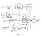
- FIG. 2 schematically showing the electronic functional architecture of the probe.
- An MUX multiplexer acquires in sequence (for example at around 2000 Hz) the following quantities: - beat angles DX1, DY1 and DY2, DZ2 of the sensitive elements of the gyroscopes G1 and G2 respectively; - beat angles DA x , DA y , DA z of the pendulums of the accelerometers respectively A x , A y , A z ; - temperature T of the heart.
- This analog information is digitized using an analog-digital ADC converter (for example on 12 digits), and passes over a serial bus 18.
- an analog-digital ADC converter for example on 12 digits
- a Processing Unit (TU) (fast micropressor and associated circuits) develops digital commands which are transmitted, via a bus 19, to precision digital / analog converters (CNAP) which translate them into respective analog currents, which are applied to the MC torque motors of the corresponding sensors.
- CNAP precision digital / analog converters
- each order sent by the microprocessor of the Processing Unit is a reflection of the analog current injected into the torque motor of the corresponding sensor, and therefore of the torque (or force) exerted on the sensitive element, these quantities balancing the couples (or force) exerted by the angular velocities (or linear accelerations) to which the probe is subjected.
- a heating command is developed by the Processing Unit UT and applied via a digital-analog converter DAC to a heating circuit 20.
- the information produced by the Processing Unit is stored at regular intervals in a non-volatile MEM memory (for example 512 k bytes).
- angles ⁇ , ⁇ , ⁇ constitute the three angles of Euler making it possible to pass from the reference frames R0 to R3; we associate them with the quaternion Q (t) (q0, q1, q2, q3) whose components are:
- This quantity defines, in other words, the passage from the mobile reference frame R3 to the fixed reference frame R0 and it lends itself well to numerical calculation methods.
- the quaternion Q (t) is periodically readjusted (at a rate of 10 Hz for example) by comparing (comparator 23), in the horizontal plane, the odometric speeds ⁇ V (after derivation with respect to time, at 24, of the odometric distance and projection in the fixed reference frame R o in 25) and the speeds ⁇ V o deduced from the accelerometric information (after projection of these in the fixed reference frame R o in 26). In case of deviation, the quaternion Q (t) is updated.
- the position of the probe (block 29) at time t + ⁇ t is defined in the fixed frame of reference R0 by its three coordinates: where B (l, c) ⁇ z3 is the projection in R0 (in 25) of the odometric increment.
- This information is stored at a rate close to 2 Hz.
- the probe traverses the tube from a starting point A to a point of arrival B, the coordinates of these two points A and B being known.
- odometric errors which contract or stretch all the lengths, they can be reduced, or even canceled, by having recourse (as indicated with reference to fig. 1) to several odometric sensors (for example two or three) whose respective information is permanently compared and of which only the information of the highest value (supposed to correspond to a bearing without sliding) is retained and used.
Abstract
Description
La présente invention concerne une sonde de mesure utilisable en vue de l'établissement du relevé topographique d'un tube non librement accessible, tel qu'un pipe-line enterré ou immergé cette sonde étant destinée à être propulsée par un fluide en circulation dans le tube et comportant :
- au moins un carter tubulaire,
- des moyens de guidage solidaires extérieurement du carter et aptes à maintenir le carter sensiblement coaxial au tube ;
- des moyens d'étanchéité interposés entre le carter et le tube pour isoler de façon étanche les parties du tube situé en amont et en aval de la sonde, de manière telle que la sonde puisse être propulsée dans le tube par le fluide en circulation ;
- des capteurs inertiels comprenant des moyens de détection accélérométrique aptes à détecter les accélérations linéaires suivant les axes d'un référentiel,
- et des moyens de traitement de données aptes à recueillir les données fournies par les capteurs, et à traiter et mémoriser les informations obtenues.The present invention relates to a measurement probe which can be used for the establishment of the topographical reading of a tube which is not freely accessible, such as a buried or submerged pipeline, this probe being intended to be propelled by a fluid circulating in the tube and comprising:
- at least one tubular casing,
- Guide means integral externally with the casing and able to keep the casing substantially coaxial with the tube;
- sealing means interposed between the casing and the tube to seal the parts of the tube located upstream and downstream of the probe, so that the probe can be propelled into the tube by the circulating fluid;
- inertial sensors comprising accelerometric detection means capable of detecting linear accelerations along the axes of a reference frame,
- And data processing means able to collect the data provided by the sensors, and to process and store the information obtained.
Il est souhaitable de pouvoir connaître avec précision la position exacte d'un tube enfoui (par exemple un pipe-line ou un gazoduc, enterré ou immergé) dont seules les deux extrémités sont accessibles. Cette connaissance est nécessaire par exemple pour éviter un endommagement du tube au cours de travaux effectués dans son voisinage immédiat, ou bien pour détecter un déplacement non contrôlé du tube (à la suite d'un glissement de terrain par exemple), ou bien encore pour déterminer les contraintes s'exerçant sur un tube suspendu en deux de ses points (pipe-line enjambant une faille sous-marine par exemple).It is desirable to be able to know precisely the exact position of a buried tube (for example a pipeline or a gas pipeline, buried or submerged) of which only the two ends are accessible. This knowledge is necessary for example to avoid damage to the tube during work carried out in its immediate vicinity, or to detect an uncontrolled displacement of the tube (following a landslide for example), or even to determine the stresses exerted on a tube suspended at two of its points (pipeline spanning an underwater fault, for example).
Une sonde du genre précitée est connue de par le brevet US 4 717 875. Toutefois son équipement est insuffisant pour effectuer des relevés complets, et avec toute la précision souhaitée, de la topographie du tube et notamment des points particuliers à détecter et/ou à surveiller.A probe of the aforementioned type is known from US Pat. No. 4,717,875. However, its equipment is insufficient to carry out complete surveys, and with all the desired precision, of the topography of the tube and in particular of the particular points to be detected and / or monitor.
L'invention a donc essentiellement pour objet de proposer une sonde de structure perfectionnée qui donne mieux satisfaction aux diverses exigences des utilisateurs, et qui en particulier procure une plus grande précision des relevés topographiques que la sonde connue précitée.The object of the invention is therefore essentially to provide a probe with an improved structure which gives better satisfaction to the various requirements of users, and which in particular provides greater precision in topographic surveys than the aforementioned known probe.
A ces fins, une sonde du genre mentionné plus haut et agencée conformément à l'invention se caractérise essentiellement en ce qu'elle comprend en outre :
- au moins un capteur odométrique extérieur au carter, coopérant avec la paroi du tube et apte à fournir un signal électrique représentatif de la distance parcourue par la sonde dans le tube ;
- des moyens de détection gyroscopique aptes à détecter les vitesses angulaires suivant les axes du susdit référentiel ;
- un barillet monté coaxialement à l'intérieur du carter et apte à tourner par rapport à celui-ci autour d'un axe sensiblement coaxial à celui du carter ; et
- un coeur abrité dans le barillet et solidaire de celui-ci dans sa rotation, sur lequel sont disposés les susdits capteurs inertiels et moyens de détection gyroscopiques, le référentiel précité étant lié au barillet.For these purposes, a probe of the kind mentioned above and arranged in accordance with the invention is essentially characterized in that it further comprises:
- At least one odometric sensor outside the casing, cooperating with the wall of the tube and capable of providing an electrical signal representative of the distance traveled by the probe in the tube;
- gyroscopic detection means capable of detecting the angular speeds along the axes of the above referential;
- A barrel mounted coaxially inside the casing and able to rotate relative to the latter about an axis substantially coaxial with that of the casing; and
- A core housed in the barrel and integral with the latter in its rotation, on which the above said inertial sensors and gyroscopic detection means are arranged, the aforementioned frame of reference being linked to the barrel.
La sonde est normalement introduite dans le tube à une de ses extrémités accessibles, puis propulsée dans le tube par la pression du fluide en circulation dans celui-ci, et récupérée à l'autre extrémité accessible du tube. Au cours de son parcours, on détecte et on mémorise des informations de positions, de vitesses angulaires, d'accélérations linéaires, et de déplacements curvilignes à partir desquelles, connaissant en outre avec précision les emplacements d'arrivée et de départ, il est possible de reconstituer le parcours de la sonde, et donc le tracé du tube.The probe is normally introduced into the tube at one of its accessible ends, then propelled into the tube by the pressure of the fluid circulating in it, and recovered at the other accessible end of the tube. During its journey, we detect and information on positions, angular velocities, linear accelerations and curvilinear displacements is memorized from which, in addition to knowing precisely the arrival and departure locations, it is possible to reconstruct the path of the probe, and so the path of the tube.
Le recours à des moyens capteurs odométriques (qui par ailleurs sont connus en eux-mêmes) est d'une importance fondamentale pour procurer une détection précise du développement linéaire du tube à inspecter et pour procurer une référence linéaire à toutes les données fournies par les autres capteurs.The use of odometric sensor means (which are also known in themselves) is of fundamental importance to provide precise detection of the linear development of the tube to be inspected and to provide a linear reference to all the data supplied by the others. sensors.
Le recours à des moyens de détection gyroscopiques permet, en conjonction avec les moyens de détection accélérométriques, d'obtenir une information précise et pratiquement instantanée sur les changements d'orientation de la trajectoire de la sonde, et donc sur les orientations respectives des tronçons successifs du tube, tout en localisant de façon précise les points remarquables (par exemple début et fin des courbes).The use of gyroscopic detection means makes it possible, in conjunction with the accelerometric detection means, to obtain precise and practically instantaneous information on changes in orientation of the trajectory of the probe, and therefore on the respective orientations of the successive sections. of the tube, while precisely locating the remarkable points (for example beginning and end of the curves).
Enfin, le recours à un barillet, abritant le coeur du dispositif, qui est monté tournant autour de son propre axe longitudinal lui-même sensiblement coaxial à l'axe du tube, permet de moyenner les écarts de mesure dus notamment aux erreurs propres introduites par les capteurs ; on effectue ainsi un relevé hélicoïdal au sein du tube qui, après traitement approprié par les moyens de traitement de données, procure une information topographique linéaire plus précise que celle obtenue par une détection purement linéaire comme c'est le cas dans les appareils. antérieurs.Finally, the use of a barrel, housing the heart of the device, which is mounted rotating around its own longitudinal axis itself substantially coaxial with the axis of the tube, makes it possible to average the measurement differences due in particular to the own errors introduced by the sensors; a helical reading is thus carried out within the tube which, after appropriate processing by the data processing means, provides more precise linear topographic information than that obtained by purely linear detection as is the case in the devices. earlier.
Pour écarter les erreurs de mesure de positionnement provoquées par un glissement sans roulement des capteurs odométriques, la sonde est équipée d'au moins deux capteurs odométriques et les moyens de traitement de données sont agencés pour comparer en permanence leurs informations respectives et ne retenir que l'information ayant la valeur la plus élevée.To avoid positioning measurement errors caused by a sliding without rolling of the odometric sensors, the probe is equipped with at least two odometric sensors and the data processing means are arranged to constantly compare their respective information and retain only the information with the highest value.
Avantageusement, dans un but de simplification, les moyens de guidage et les moyens d'étanchéité sont réunis ensembles sous forme d'au moins deux jupes annulaires qui entourent le carter respectivement vers l'avant et l'arrière de celui-ci et dont les bords libres annulaires coopèrent de façon étanche avec la paroi du tube.Advantageously, for the sake of simplification, the guide means and the sealing means are joined together in the form of at least two annular skirts which surround the casing respectively towards the front and the rear thereof and whose free annular edges cooperate tightly with the wall of the tube.
Dans un mode de réalisation avantageux, les moyens de détection accélérométriques comprennent trois accéléromètres à un axe sensible détectant les accélérations linéaires suivant respectivement trois axes du référentiel lié au barillet. De même, les moyens de détection gyroscopiques peuvent comprendre deux gyroscopes à deux axes sensibles détectant les vitesses angulaires suivant respectivement deux des axes du référentiel lié au barillet. Une redondance dans la position des axes sensibles des gyroscopes permet de déceler et/ou de compenser certaines erreurs de référencement.In an advantageous embodiment, the accelerometric detection means comprise three accelerometers with a sensitive axis detecting the linear accelerations along respectively three axes of the reference frame linked to the barrel. Likewise, the gyroscopic detection means may comprise two gyroscopes with two sensitive axes detecting the angular velocities along respectively two of the axes of the reference frame linked to the barrel. Redundancy in the position of the sensitive axes of the gyroscopes makes it possible to detect and / or compensate for certain referencing errors.
De façon souhaitable, pour éviter une dérive thermique des composants et procurer une meilleure fiabilité, la sonde comporte en outre des moyens de thermostatage pour réguler la température interne du barillet à une valeur prédéterminée.Desirably, in order to avoid thermal drift of the components and to provide better reliability, the probe further comprises thermostating means for regulating the internal temperature of the barrel to a predetermined value.
Toujours pour accroître la fiabilité, le coeur peut être monté dans le barillet par l'intermédiaire de moyens de suspension aptes à amortir les chocs et les vibrations.Still to increase reliability, the core can be mounted in the barrel by means of suspension means able to absorb shocks and vibrations.
Pour accroître l'autonomie de fonctionnement de la sonde et lui permettre d'effectuer des relevés dans des tubes de grande longueur, la sonde peut comporter en outre un second carter renfermant des moyens de fourniture d'énergie électrique, ce second carter étant attelé au premier carter et raccordé à celui-ci par des liaisons électriquement conductrices.To increase the operating autonomy of the probe and allow it to take measurements in very long tubes, the probe can include in addition to a second casing containing means for supplying electrical energy, this second casing being coupled to the first casing and connected to the latter by electrically conductive links.
L'invention sera mieux comprise à la lecture de la description détaillée qui suit d'un mode de réalisation préféré, donné uniquement à titre d'exemple non limitatif ; dans cette description on se réfère aux dessins annexés sur lesquels :
- - la figure 1 est une vue schématique en coupe diamétrale d'une sonde agencée conformément à l'invention ;
- - la figure 2 est un schéma-bloc illustrant l'agencement fonctionnel électronique général de la sonde ; et
- - la figure 3 est un schéma-bloc illustrant les moyens électroniques mis en oeuvre pour la détermination de la position instantanée de la sonde.
- - Figure 1 is a schematic view in diametral section of a probe arranged in accordance with the invention;
- - Figure 2 is a block diagram illustrating the general electronic functional arrangement of the probe; and
- - Figure 3 is a block diagram illustrating the electronic means used for determining the instantaneous position of the probe.
En se référant tout d'abord à la figure 1, la sonde, désignée dans son ensemble par la référence numérique 1, comprend un carter 2 sous forme d'un élément tubulaire allongé et étanche maintenu, par des moyens de guidage, sensiblement coaxialement à l'axe 3 du tube (dont seule la surface interne est schématisée par un trait mixte 4) dans lequel la sonde est appelée à se déplacer.Referring firstly to FIG. 1, the probe, designated as a whole by the reference numeral 1, comprises a
Dans l'exemple représenté, les moyens de guidage sont agencés sous forme d'au moins deux jupes annulaires 5, disposées respectivement approximativement vers l'avant et vers l'arrière du carter 2 (le sens de déplacement de la sonde est symbolisé par la flèche 6), qui entourent le carter et s'étendent entre le carter 2 et la surface 4 du tube.In the example shown, the guide means are arranged in the form of at least two
Cet agencement offre en outre l'avantage que ces mêmes jupes 5 peuvent également jouer le rôle de moyens d'étanchéité en étant munies chacune d'un bord périphérique 7 formant joint d'étanchéité, coopérant de façon étanche avec la surface 4 du tube.This arrangement also offers the advantage that these
Ces jupes 5 ainsi conçues isolent l'une de l'autre de façon étanche les zones du tube situées respectivement à l'arrière et à l'avant du carter 2 et la sonde peut ainsi être propulsée à l'intérieur du tube simplement par un fluide en circulation dans le tube.These
Toujours a l'extérieur du carter 2 se trouvent au moins deux capteurs odométriques 8 comportant chacun un bras 9 articulé en rotation sur le carter 2 et supportant à son extrémité libre une roue folle 10 maintenue appliquée élastiquement contre la surface 4 du tube en vue de son roulement sans glissement sur cette surface. Les roues 10 sont agencées (avec des moyens connus en soi et non visibles sur la fig. 1) pour délivrer chacune une impulsion électrique par tour.Still outside the
A l'intérieur du carter 2 est disposé un barillet 11 monté coaxialement au carter et apte à tourner autour d'un axe longitudinal parallèle (et coaxial autant que possible) à l'axe 3 du tube. A cet effet, le barillet 11 est muni d'arbres d'extrémité 12 supportés dans des paliers respectifs 13 solidaires du carter 2. Un moteur électrique 14 permet de communiquer au barillet une vitesse de rotation de l'ordre de 1 tour par minute.Inside the
Un ensemble de contacts électriques (non représentés) permet de faire transiter les informations odométriques jusqu' au barillet et d'alimenter le barillet en énergie électrique à partir d'une source d'énergie électrique (batterie) non représentée. Cette source peut être prévue à l'intérieur du carter ; mais pour des parcours relativement longs (pouvant par exemple durer plusieurs heures), cette source électrique, devenue très lourde et volumineuse, peut être reportée dans un second véhicule attelé mécaniquement et électriquement au premier précité (liaison 15 sur la fig. 1).A set of electrical contacts (not shown) makes it possible to transmit the odometric information to the barrel and to supply the barrel with electrical energy from a source of electrical energy (battery) not shown. This source can be provided inside the casing; but for relatively long journeys (which can last for several hours for example), this electrical source, which has become very heavy and bulky, can be carried in a second harnessed vehicle mechanically and electrically to the first aforementioned (
Le barillet 11 inclut un coeur 16 regroupant plusieurs capteurs inertiels, savoir :
- trois accéléromètres Ax, Ay et Az à un axe sensible détectant les accélérations linéaires suivant trois axes (schématisés respectivement par trois flèches) d'un référentiel lié au barillet ;
- et deux gyroscopes G₁ et G₂ à deux axes sensibles détectant les vitesses angulaires suivant les axes du référentiel précité (respectivement axes x et y pour le gyroscope G₁ et axes y et z pour le gyroscope G₂), le recours à ce type de capteurs imposant une redondance dans la disposition des axes sensibles.The
- three accelerometers A x , A y and A z with a sensitive axis detecting the linear accelerations along three axes (shown diagrammatically by three arrows) of a reference frame linked to the barrel;
- and two gyros G₁ and G₂ with two sensitive axes detecting the angular velocities along the axes of the above-mentioned reference frame (respectively x and y axes for the G₁ gyroscope and y and z axes for the G₂ gyroscope), the use of this type of imposing sensors redundancy in the layout of sensitive axes.
Le coeur est suspendu pour préserver les capteurs accélérométriques et gyrométriques d'un endommagement dû à des chocs, et il est thermostaté pour éviter toute dérive thermique des capteurs et leur conserver leur précision, source de la fiabilité des mesures effectuées et de la précision subséquente du relevé topographique qui en est déduit.The core is suspended to preserve the accelerometric and gyrometric sensors from damage due to shocks, and it is thermostatically controlled to avoid any thermal drift of the sensors and to keep their accuracy, which is the source of the reliability of the measurements carried out and the subsequent accuracy of the topographical statement which is deduced therefrom.
Le barillet 11 contient également le matériel électronique destiné à assurer l'alimentation des capteurs, la gestion de la régulation thermique du coeur 16, l'asservissement des capteurs, l'acquisition des mesures gyrométriques accélérométriques et odométriques par un calculateur, le traitement de ces informations et leur stockage dans une mémoire.The
Enfin, un ensemble de connecteurs permet, après un parcours de la sonde dans un tube, d'accéder aux informations mémorisées pour leur traitement et la reconstitution du parcours, permettant d'en déduire la topographie précise du tube entre les points de départ et d'arrivée de la sonde.Finally, a set of connectors allows, after a journey of the probe in a tube, to access the information stored for their processing and the reconstruction of the journey, allowing to deduce the precise topography of the tube between the starting points and d arrival of the probe.
On va maintenant expliquer le mode de fonctionnement de la sonde qui vient d'être décrite, en se référant aux figures 2 et 3.We will now explain the operating mode of the probe which has just been described, by referring to Figures 2 and 3.
On rappellera tout d'abord que les capteurs inertiels sont constitués d'un élément sensible (pendule pour l'accéléromètre, volant pour le gyroscope) qui doit être asservi en position. La mesure des efforts ou des couples de rappel est l'image de la grandeur physique à mesurer (accélération linéaire ou vitesse angulaire respectivement).First of all, it will be recalled that the inertial sensors consist of a sensitive element (pendulum for the accelerometer, steering wheel for the gyroscope) which must be controlled in position. The measurement of the forces or of the restoring torques is the image of the physical quantity to be measured (linear acceleration or angular speed respectively).
On se reportera tout d'abord à la fig. 2 montrant schématiquement l'architecture fonctionnelle életronique de la sonde.We will firstly refer to FIG. 2 schematically showing the electronic functional architecture of the probe.
Un multiplexeur MUX fait l'acquisition en séquence (par exemple à 2000 Hz environ) des grandeurs suivantes :
- angles de battement DX₁, DY₁ et DY₂, DZ₂ des éléments sensibles des gyroscopes respectivement G₁ et G₂ ;
- angles de battement DAx, DAy, DAz des pendules des accéléromètres respectivement Ax, Ay, Az ;
- température T du coeur.An MUX multiplexer acquires in sequence (for example at around 2000 Hz) the following quantities:
- beat angles DX₁, DY₁ and DY₂, DZ₂ of the sensitive elements of the gyroscopes G₁ and G₂ respectively;
- beat angles DA x , DA y , DA z of the pendulums of the accelerometers respectively A x , A y , A z ;
- temperature T of the heart.
Ces informations analogiques sont numérisées à l'aide d'un convertisseur analogique-numérique CAN (par exemple sur 12 digits), et transitent sur un bus série 18.This analog information is digitized using an analog-digital ADC converter (for example on 12 digits), and passes over a
Une Unité de Traitement (UT) (micropresseur rapide et circuits associés) élabore des commandes numériques qui sont transmises, par un bus 19, à des convertisseurs numérique/analogique de précision (CNAP) qui les traduisent en courants analogiques respectifs, lesquels sont appliqués aux moteurs-couples MC des capteurs correspondants. Si la conversion est précise, chaque ordre envoyé par le microprocesseur de l'Unité de Traitement est le reflet du courant analogique injecté dans le moteur-couple du capteur correspondant, et donc du couple (ou de la force) s'exerçant sur l'élément sensible, ces grandeurs équilibrant les couples (ou force) exercées par les vitesses angulaires (ou les accélérations linéaires) auxquelles la sonde est soumise.A Processing Unit (TU) (fast micropressor and associated circuits) develops digital commands which are transmitted, via a
De plus, une commande de chauffage est élaborée par l'Unité de Traitement UT et appliquée via un convertisseur numérique-analogique CNA à un circuit de chauffage 20.In addition, a heating command is developed by the Processing Unit UT and applied via a digital-analog converter DAC to a
Enfin, les informations élaborées par l'Unité de Traitement sont stockées à intervalles réguliers dans une mémoire MEM non volatile (par exemple de 512 k octets).Finally, the information produced by the Processing Unit is stored at regular intervals in a non-volatile MEM memory (for example 512 k bytes).
L'élaboration des coordonnées du parcours s'effectue de la manière suivante (on se réfère simultanément à la fig. 3 qui schématise la constitution de l'électronique élaborée pour réaliser ce fonctionnement).The coordinates of the route are drawn up in the following manner (reference is made simultaneously to FIG. 3 which diagrams the constitution of the electronics developed to perform this operation).
Tout d'abord, on définit quatre référentiels comme suit :
- a) R₀ (i₀, j₀, k₀) est un premier référentiel où:
i₀ est colinéaire à la gravité locale,
j₀ est orienté vers l'est ; - b) R₁ (i₁, j₁, k₁) est un deuxième référentiel déduit de R₀ par rotation de l'angle de cap autour de i₀ = i₁ ; le plan (i₁, k₁) est donc vertical et tangent au tube ;
- c) R₂ (i₂, j₂, k₂) est un troisième référentiel déduit de R₁ par rotation de l'angle d'inclinaison ϑ autour de j₁ = j₂ ; le vecteur k₂ est donc tangent à l'axe du tube ;
- d) R₃ (i₃, j₃, k₃) est un quatrième référentiel déduit de R₂ par rotation de l'angle de vrillage autour de k₂ = k₃ ; le référentiel R₃ est donc lié au coeur inertiel.
- a) R₀ (i₀, j₀, k₀) is a first frame of reference where:
i₀ is collinear with local gravity,
j₀ is oriented to the east; - b) R₁ (i₁, j₁, k₁) is a second frame of reference deduced from R₀ by rotation of the heading angle around i₀ = i₁; the plane (i₁, k₁) is therefore vertical and tangent to the tube;
- c) R₂ (i₂, j₂, k₂) is a third frame of reference deduced from R₁ by rotation of the angle of inclination ϑ around j₁ = j₂; the vector k₂ is therefore tangent to the axis of the tube;
- d) R₃ (i₃, j₃, k₃) is a fourth reference system deduced from R₂ by rotation of the twist angle around k₂ = k₃; the reference frame R₃ is therefore linked to the inertial core.
On notera qu'à l'instant t = 0 les 4 référentiels coïncident.It will be noted that at time t = 0 the 4 reference frames coincide.
L'élaboration des coordonnées du parcours de la sonde à l'intérieur du tube s'effectue comme suit.The coordinates of the path of the probe inside the tube are worked out as follows.
Les angles φ, ϑ, Ψ constituent les trois angles d'Euler permettant de passer des référentiels R₀ à R₃ ; on leur associe le quaternion Q(t) (q₀, q₁, q₂, q₃) dont les composantes sont :
Cette grandeur définit, en d'autres termes, le passage du référentiel mobile R₃ au référentiel fixe R₀ et elle se prête bien aux méthodes de calculs numériques.This quantity defines, in other words, the passage from the mobile reference frame R₃ to the fixed reference frame R₀ and it lends itself well to numerical calculation methods.
Lorsqu' une vitesse de rotation instantanée Ω est appliquée à la sonde, le quaternion Q(t) évolue suivant l'équation différentielle suivante :
(2) ![]()
où Ω est le quaternion associé à .When an instantaneous speed of rotation Ω is applied to the probe, the quaternion Q (t) evolves according to the following differential equation:
(2) ![]()
where Ω is the quaternion associated with.
Cette équation a pour solution :
Elle est normalement résolue par des méthodes utilisant des développements limités (Méthodes d'EDWARDS, de WILCOX ou de TAYLOR) (bloc 21 de la fig. 3).It is normally solved by methods using limited developments (EDWARDS, WILCOX or TAYLOR methods) (
Q(t) étant ainsi connu, on calcule la matrice de passage B (l, c) de R₃ à R₀ (bloc 22) : (formule (3))
Ces calculs sont conduits à une fréquence de par exemple 100 Hz environ.These calculations are carried out at a frequency of for example around 100 Hz.
En réalité le quaternion Q(t) ainsi calculé par la relation (2) à l'aide des seules vitesses angulaires est affecté d'erreurs dues principalement aux gyroscopes utilisés ; ceux-ci fournissent en effet une mesure de vitesses angulaire (appelée "dérive") même s'ils ne sont pas sollicités. De ce fait, le quaternion Q(t) "dérive" et les trois angles d'Euler calculés par la relation (3) évolueraient dans le temps au rythme de la dérive des gyroscopes.In reality the quaternion Q (t) thus calculated by the relation (2) using only the angular velocities is affected by errors due mainly to the gyroscopes used; these indeed provide an angular velocity measurement (called "drift") even if they are not used. Therefore, the quaternion Q (t) "drifts" and the three Euler angles calculated by the relation (3) would evolve in time to the rhythm of the drift of the gyroscopes.
Cette erreur est en partie annulée en utilisant les informations accélérométriques. On "recale" périodiquement le quaternion Q(t) (à une cadence de 10 Hz par exemple) en comparant (comparateur 23), dans le plan horizontal, les vitesses odométriques ΔV (après dérivation par rapport au temps, en 24, de la distance odométrique et projection dans le référentiel fixe Ro en 25) et les vitesses ΔVo déduites des informations accélérométriques (après projection de celles-ci dans le référentiel fixe Ro en 26). En cas d'écart, le quaternion Q(t) est remis à jour.This error is partially cleared using the accelerometric information. The quaternion Q (t) is periodically readjusted (at a rate of 10 Hz for example) by comparing (comparator 23), in the horizontal plane, the odometric speeds ΔV (after derivation with respect to time, at 24, of the odometric distance and projection in the fixed reference frame R o in 25) and the speeds ΔV o deduced from the accelerometric information (after projection of these in the fixed reference frame R o in 26). In case of deviation, the quaternion Q (t) is updated.
On notera que après projection dans le référentiel R₃ (bloc 27), la vitesse de rotation terrestre ΩT est également soustraite des vitesses angulaires détectées (comparateur 28).It will be noted that after projection into the reference frame R₃ (block 27), the terrestrial speed of rotation Ω T is also subtracted from the angular speeds detected (comparator 28).
La position de la sonde (bloc 29) à l'instant t + Δt est définie dans le référentiel fixe R₀ par ses trois coordonnées :
Ces informations sont mémorisées à une cadence voisine de 2 Hz.This information is stored at a rate close to 2 Hz.
Le dépouillement des données s'effectue comme suit.Data analysis is carried out as follows.
La sonde parcourt le tube d'un point de départ A vers un point d'arrivée B, les coordonnées de ces deux points A et B étant connues.The probe traverses the tube from a starting point A to a point of arrival B, the coordinates of these two points A and B being known.
Tout au long du parcours, la position M(t) d'un point courant va pouvoir être estimée et cette position restituée [xM(t), yM(t), zM(t)]. Au point B on va constater un vecteur d'erreur :
En définitive, on notera que les erreurs de "dérive" du gyroscope de cap, sont éliminées en raison de la rotation continue du barillet dans la sonde.Ultimately, it will be noted that the errors of "drift" of the heading gyroscope are eliminated due to the continuous rotation of the barrel in the probe.
Quant aux erreurs odométriques qui contractent ou étirent toutes les longueurs, elles peuvent être diminuées, voire annulées, en ayant recours (comme indiqué en référence à la fig. 1) à plusieurs capteurs odométriques (par exemple deux ou trois) dont les informations respectives sont comparées en permanence et dont seule l'information de valeur la plus élevée (supposée correspondre à un roulement sans glissement) est retenue et utilisée.As for the odometric errors which contract or stretch all the lengths, they can be reduced, or even canceled, by having recourse (as indicated with reference to fig. 1) to several odometric sensors (for example two or three) whose respective information is permanently compared and of which only the information of the highest value (supposed to correspond to a bearing without sliding) is retained and used.
Comme il va de soi et comme il résulte d'ailleurs déjà de ce qui précède, l'invention ne se limite nullement à ceux de ses modes d'application et de réalisation qui ont été plus particulièrement envisagés ; elle en embrasse, au contraire, toutes les variantes.As it goes without saying and as it already follows from the above, the invention is not limited in no way to those of its modes of application and embodiments which have been more particularly envisaged; on the contrary, it embraces all its variants.
Claims (7)
- au moins un carter tubulaire (2),
- des moyens de guidage (5) solidaires extérieurement du carter (2) et aptes à maintenir le carter sensiblement coaxial au tube ;
- des moyens d'étanchéité (7) interposés entre le carter et le tube pour isoler de façon étanche les parties du tube situé en amont et en aval de la sonde, de manière telle que la sonde puisse être propulsée dans le tube par le fluide en circulation ;
- des capteurs inertiels comprenant des moyens de détection accélérométrique (Ax, Ay, Az) aptes à détecter les accélérations linéaires suivant les axes d'un référentiel,
- et des moyens de traitement de données (17) aptes à recueillir les données fournies par les capteurs, et à traiter et mémoriser les informations obtenues,
caractérisé en ce qu'elle comprend en outre :
- au moins un capteur odométrique (10) extérieur au carter, coopérant avec la paroi (4) du tube et apte à fournir un signal électrique représentatif de la distance parcourue par la sonde dans le tube ;
- des moyens de détection gyroscopique (G₁, G₂) aptes à détecter les vitesses angulaires suivant les axes du susdit référentiel ;
- un barillet (11) monté coaxialement à l'intérieur du carter (2) et apte à tourner par rapport à celui-ci autour d'un axe sensiblement coaxial à celui du carter; et
- un coeur (16) abrité dans le barillet (11) et solidaire de celui-ci dans sa rotation, sur lequel sont disposés les susdits capteurs inertiels et moyens de détection gyroscopiques, le référentiel précité étant lié au barillet.1. Measuring probe (1) usable with a view to establishing the topographical reading of a tube which is not freely accessible, such as a buried or submerged pipeline, this probe being intended to be propelled by a fluid circulating in the tube and comprising:
- at least one tubular casing (2),
- Guide means (5) integral externally with the casing (2) and able to keep the casing substantially coaxial with the tube;
- sealing means (7) interposed between the casing and the tube for sealing the parts of the tube located upstream and downstream of the probe, so that the probe can be propelled into the tube by the fluid outstanding;
- inertial sensors comprising accelerometric detection means (A x , A y , A z ) capable of detecting linear accelerations along the axes of a frame of reference,
- and data processing means (17) able to collect the data supplied by the sensors, and to process and store the information obtained,
characterized in that it further comprises:
- at least one odometric sensor (10) outside the casing, cooperating with the wall (4) of the tube and capable of providing an electrical signal representative of the distance traveled by the probe in the tube;
- gyroscopic detection means (G₁, G₂) capable of detecting the angular velocities along the axes of the above referential;
- A barrel (11) mounted coaxially inside the casing (2) and able to rotate relative to the latter about an axis substantially coaxial with that of the casing; and
- a heart (16) housed in the barrel (11) and integral with the latter in its rotation, on which the above said inertial sensors and gyroscopic detection means are arranged, the aforementioned frame of reference being linked to the barrel.
Priority Applications (1)
| Application Number | Priority Date | Filing Date | Title |
|---|---|---|---|
| AT89400909T ATE71705T1 (en) | 1988-04-07 | 1989-04-03 | PIG FOR MEASURING THE TOPOGRAPHIC ARRANGEMENT OF A PIPELINE THAT IS NOT FREELY ACCESSIBLE. |
Applications Claiming Priority (2)
| Application Number | Priority Date | Filing Date | Title |
|---|---|---|---|
| FR8804615 | 1988-04-07 | ||
| FR8804615A FR2629898B1 (en) | 1988-04-07 | 1988-04-07 | MEASUREMENT PROBE FOR USE IN ESTABLISHING THE TOPOGRAPHIC SURVEY OF A NON-FREELY ACCESSIBLE TUBE |
Publications (2)
| Publication Number | Publication Date |
|---|---|
| EP0336828A1 true EP0336828A1 (en) | 1989-10-11 |
| EP0336828B1 EP0336828B1 (en) | 1992-01-15 |
Family
ID=9365075
Family Applications (1)
| Application Number | Title | Priority Date | Filing Date |
|---|---|---|---|
| EP89400909A Expired - Lifetime EP0336828B1 (en) | 1988-04-07 | 1989-04-03 | Pig for measuring the topographic layout of a not freely accessible pipeline |
Country Status (6)
| Country | Link |
|---|---|
| EP (1) | EP0336828B1 (en) |
| AT (1) | ATE71705T1 (en) |
| DE (1) | DE68900699D1 (en) |
| ES (1) | ES2028453T3 (en) |
| FR (1) | FR2629898B1 (en) |
| GR (1) | GR3003580T3 (en) |
Cited By (4)
| Publication number | Priority date | Publication date | Assignee | Title |
|---|---|---|---|---|
| WO1992009847A1 (en) * | 1990-11-22 | 1992-06-11 | Hugh Edmund Murray Hunt | Pipeline pig and method of pipeline inspection |
| GB2315866A (en) * | 1996-08-01 | 1998-02-11 | Radiodetection Ltd | Position detection |
| WO2000008377A1 (en) * | 1998-08-04 | 2000-02-17 | Chernyaev Konstantin Valerievi | Device for measuring and for checking with causing any damage the material of a duct |
| CN114992530A (en) * | 2022-07-07 | 2022-09-02 | 大连理工大学 | Oil pipeline monitoring system |
Families Citing this family (1)
| Publication number | Priority date | Publication date | Assignee | Title |
|---|---|---|---|---|
| DE102004050168A1 (en) * | 2004-10-14 | 2006-04-20 | Murrplastik Systemtechnik Gmbh | Protective sleeve for corrugated hoses used in machines is made up of two semicircular sections with transverse internal ribs which hold it in position on hose, sections being connected by hinge, making it easier to fit |
Citations (4)
| Publication number | Priority date | Publication date | Assignee | Title |
|---|---|---|---|---|
| DE2354117A1 (en) * | 1972-10-30 | 1974-05-09 | Shell Int Research | METHOD AND DEVICE FOR MEASURING THE DISTANCE COVERED BY AN INSPECTION EQUIPMENT MOVED THROUGH A PIPELINE |
| GB2130721A (en) * | 1982-11-22 | 1984-06-06 | Litton Systems Inc | Measurement of pipeline deflection |
| DE3511774A1 (en) * | 1985-03-30 | 1986-10-02 | Pipetronix GmbH, 7500 Karlsruhe | Measuring pig for pipelines |
| US4717875A (en) * | 1986-02-19 | 1988-01-05 | Atlantic Richfield Company | Method and system for determining curvature in fluid transmission pipelines |
-
1988
- 1988-04-07 FR FR8804615A patent/FR2629898B1/en not_active Expired - Lifetime
-
1989
- 1989-04-03 DE DE8989400909T patent/DE68900699D1/en not_active Expired - Lifetime
- 1989-04-03 AT AT89400909T patent/ATE71705T1/en not_active IP Right Cessation
- 1989-04-03 ES ES198989400909T patent/ES2028453T3/en not_active Expired - Lifetime
- 1989-04-03 EP EP89400909A patent/EP0336828B1/en not_active Expired - Lifetime
-
1992
- 1992-01-16 GR GR910402010T patent/GR3003580T3/el unknown
Patent Citations (4)
| Publication number | Priority date | Publication date | Assignee | Title |
|---|---|---|---|---|
| DE2354117A1 (en) * | 1972-10-30 | 1974-05-09 | Shell Int Research | METHOD AND DEVICE FOR MEASURING THE DISTANCE COVERED BY AN INSPECTION EQUIPMENT MOVED THROUGH A PIPELINE |
| GB2130721A (en) * | 1982-11-22 | 1984-06-06 | Litton Systems Inc | Measurement of pipeline deflection |
| DE3511774A1 (en) * | 1985-03-30 | 1986-10-02 | Pipetronix GmbH, 7500 Karlsruhe | Measuring pig for pipelines |
| US4717875A (en) * | 1986-02-19 | 1988-01-05 | Atlantic Richfield Company | Method and system for determining curvature in fluid transmission pipelines |
Cited By (8)
| Publication number | Priority date | Publication date | Assignee | Title |
|---|---|---|---|---|
| WO1992009847A1 (en) * | 1990-11-22 | 1992-06-11 | Hugh Edmund Murray Hunt | Pipeline pig and method of pipeline inspection |
| AU653974B2 (en) * | 1990-11-22 | 1994-10-20 | Hugh Edmund Murray Hunt | Pipeline pig and method of pipeline inspection |
| US5385049A (en) * | 1990-11-22 | 1995-01-31 | Hunt; Hugh E. M. | Pipeline pig and method of pipeline inspection |
| GB2315866A (en) * | 1996-08-01 | 1998-02-11 | Radiodetection Ltd | Position detection |
| GB2315866B (en) * | 1996-08-01 | 2001-01-10 | Radiodetection Ltd | Position detection |
| WO2000008377A1 (en) * | 1998-08-04 | 2000-02-17 | Chernyaev Konstantin Valerievi | Device for measuring and for checking with causing any damage the material of a duct |
| CN114992530A (en) * | 2022-07-07 | 2022-09-02 | 大连理工大学 | Oil pipeline monitoring system |
| CN114992530B (en) * | 2022-07-07 | 2023-03-10 | 大连理工大学 | Oil pipeline monitoring system |
Also Published As
| Publication number | Publication date |
|---|---|
| ATE71705T1 (en) | 1992-02-15 |
| DE68900699D1 (en) | 1992-02-27 |
| GR3003580T3 (en) | 1993-03-16 |
| ES2028453T3 (en) | 1992-07-01 |
| EP0336828B1 (en) | 1992-01-15 |
| FR2629898A1 (en) | 1989-10-13 |
| FR2629898B1 (en) | 1990-08-03 |
Similar Documents
| Publication | Publication Date | Title |
|---|---|---|
| EP0571239B1 (en) | Process and device for earth acquisition via the polar star for triaxially stabilised satellite on a small inclination orbit | |
| EP0363243B1 (en) | Method and system for autonomously controlling the orbit of a geostationary satellite | |
| EP0076179B1 (en) | Process to align the roll axis of a satellite with a desired direction | |
| EP0493228B1 (en) | Method of attitude recognition for a three axis stabilized satellite using star recognition | |
| FR2595147A1 (en) | METHOD FOR DETERMINING THE TERRESTRIAL MAGNETIC FIELD AND THE POSITION FOR CONTROLLING THE ORIENTATION OF A SATELLITE | |
| EP2361368A1 (en) | Method for determining a heading in the direction of true north using an inertial measurement unit | |
| EP0031744B1 (en) | Method and apparatus for determining the flowing properties of a fluid | |
| EP2495531B1 (en) | Method for measuring the stability of a line of sight and corresponding star sensor | |
| EP0336828B1 (en) | Pig for measuring the topographic layout of a not freely accessible pipeline | |
| FR2536533A1 (en) | METHOD AND APPARATUS, SUCH AS A SCRATCH PISTON, FOR CONTROLLING THE BENDING OF A PIPE | |
| EP0258085B1 (en) | Gyroscopic horizon | |
| EP0209429A1 (en) | Method and device for placing a 3-axis stabilized satellite into a geostationary orbit | |
| EP0575240B1 (en) | Distance incasuring device for a vehicle, especially an off-road robot and vehicle equipped with such a device | |
| WO2012152669A1 (en) | Device and method for determining the attitude of a satellite, and satellite carrying such a device | |
| EP1533600A1 (en) | Sensor system for measuring absolute values of a torsional moment and module comprising such a system | |
| FR2610411A1 (en) | METHOD AND DEVICE FOR MEASURING SPEED IN RELATION TO AIR OF A LOW SPEED HELICOPTER | |
| FR2929396A1 (en) | Location indication providing system for vehicle in automobile field, has portable object equipped with signal processing unit that processes signal delivered by inertial device for determining trajectories followed by portable object | |
| EP0341130A1 (en) | Method for slewing the inertial moment of a spinning body in space up to a given direction | |
| FR2525359A1 (en) | METHOD AND DEVICE FOR ATTITUDE REGULATION OF AN ARTIFICIAL TERRESTRIAL SATELLITE | |
| EP0321342B1 (en) | Inertial stabilizing device for the inclination of orientable elements and telescope mirror mounted on this device | |
| FR2697651A1 (en) | Calibration procedure for gyroscopic meters on stabilised satellites - involves using satellite command system and solar, stellar and terrestrial measurements to determine constant gyroscopic drift | |
| EP0267086B1 (en) | Spacecraft with an antenna earth pointing device | |
| EP0717264A1 (en) | Procedure and device for estimating gyrometric biases | |
| CA2200547A1 (en) | Procedure and mechanism for quick manoeuvring of a payload mounted on a space platform | |
| FR2513373A1 (en) | IMPROVEMENTS IN GYROSCOPIC NAVIGATION FACILITIES WITH STEERING OR STABILIZATION FUNCTIONS |
Legal Events
| Date | Code | Title | Description |
|---|---|---|---|
| PUAI | Public reference made under article 153(3) epc to a published international application that has entered the european phase |
Free format text: ORIGINAL CODE: 0009012 |
|
| AK | Designated contracting states |
Kind code of ref document: A1 Designated state(s): AT BE CH DE ES GB GR IT LI LU NL SE |
|
| 17P | Request for examination filed |
Effective date: 19900126 |
|
| 17Q | First examination report despatched |
Effective date: 19900522 |
|
| GRAA | (expected) grant |
Free format text: ORIGINAL CODE: 0009210 |
|
| AK | Designated contracting states |
Kind code of ref document: B1 Designated state(s): AT BE CH DE ES GB GR IT LI LU NL SE |
|
| REF | Corresponds to: |
Ref document number: 71705 Country of ref document: AT Date of ref document: 19920215 Kind code of ref document: T |
|
| GBT | Gb: translation of ep patent filed (gb section 77(6)(a)/1977) | ||
| REF | Corresponds to: |
Ref document number: 68900699 Country of ref document: DE Date of ref document: 19920227 |
|
| ITF | It: translation for a ep patent filed |
Owner name: DR. ING. A. RACHELI & C. |
|
| REG | Reference to a national code |
Ref country code: ES Ref legal event code: FG2A Ref document number: 2028453 Country of ref document: ES Kind code of ref document: T3 |
|
| PLBE | No opposition filed within time limit |
Free format text: ORIGINAL CODE: 0009261 |
|
| STAA | Information on the status of an ep patent application or granted ep patent |
Free format text: STATUS: NO OPPOSITION FILED WITHIN TIME LIMIT |
|
| REG | Reference to a national code |
Ref country code: GR Ref legal event code: FG4A Free format text: 3003580 |
|
| 26N | No opposition filed | ||
| PGFP | Annual fee paid to national office [announced via postgrant information from national office to epo] |
Ref country code: GB Payment date: 19930326 Year of fee payment: 5 Ref country code: AT Payment date: 19930326 Year of fee payment: 5 |
|
| PGFP | Annual fee paid to national office [announced via postgrant information from national office to epo] |
Ref country code: DE Payment date: 19930401 Year of fee payment: 5 |
|
| PGFP | Annual fee paid to national office [announced via postgrant information from national office to epo] |
Ref country code: ES Payment date: 19930416 Year of fee payment: 5 |
|
| PGFP | Annual fee paid to national office [announced via postgrant information from national office to epo] |
Ref country code: CH Payment date: 19930419 Year of fee payment: 5 |
|
| PGFP | Annual fee paid to national office [announced via postgrant information from national office to epo] |
Ref country code: SE Payment date: 19930426 Year of fee payment: 5 |
|
| PGFP | Annual fee paid to national office [announced via postgrant information from national office to epo] |
Ref country code: NL Payment date: 19930430 Year of fee payment: 5 Ref country code: GR Payment date: 19930430 Year of fee payment: 5 |
|
| PGFP | Annual fee paid to national office [announced via postgrant information from national office to epo] |
Ref country code: LU Payment date: 19930503 Year of fee payment: 5 |
|
| PGFP | Annual fee paid to national office [announced via postgrant information from national office to epo] |
Ref country code: BE Payment date: 19930513 Year of fee payment: 5 |
|
| EPTA | Lu: last paid annual fee | ||
| PG25 | Lapsed in a contracting state [announced via postgrant information from national office to epo] |
Ref country code: LU Free format text: LAPSE BECAUSE OF NON-PAYMENT OF DUE FEES Effective date: 19940403 Ref country code: GB Effective date: 19940403 Ref country code: AT Effective date: 19940403 |
|
| PG25 | Lapsed in a contracting state [announced via postgrant information from national office to epo] |
Ref country code: SE Effective date: 19940404 Ref country code: ES Free format text: LAPSE BECAUSE OF NON-PAYMENT OF DUE FEES Effective date: 19940404 |
|
| PG25 | Lapsed in a contracting state [announced via postgrant information from national office to epo] |
Ref country code: LI Effective date: 19940430 Ref country code: CH Effective date: 19940430 Ref country code: BE Effective date: 19940430 |
|
| BERE | Be: lapsed |
Owner name: SOC. D'APPLICATIONS GENERALES D'ELECTRICITE ET DE Effective date: 19940430 |
|
| PG25 | Lapsed in a contracting state [announced via postgrant information from national office to epo] |
Ref country code: GR Free format text: THE PATENT HAS BEEN ANNULLED BY A DECISION OF A NATIONAL AUTHORITY Effective date: 19941031 |
|
| PG25 | Lapsed in a contracting state [announced via postgrant information from national office to epo] |
Ref country code: NL Effective date: 19941101 |
|
| GBPC | Gb: european patent ceased through non-payment of renewal fee |
Effective date: 19940403 |
|
| NLV4 | Nl: lapsed or anulled due to non-payment of the annual fee | ||
| REG | Reference to a national code |
Ref country code: CH Ref legal event code: PL |
|
| PG25 | Lapsed in a contracting state [announced via postgrant information from national office to epo] |
Ref country code: DE Effective date: 19950103 |
|
| EUG | Se: european patent has lapsed |
Ref document number: 89400909.1 Effective date: 19941110 |
|
| REG | Reference to a national code |
Ref country code: GR Ref legal event code: MM2A Free format text: 3003580 |
|
| REG | Reference to a national code |
Ref country code: ES Ref legal event code: FD2A Effective date: 19990301 |
|
| PG25 | Lapsed in a contracting state [announced via postgrant information from national office to epo] |
Ref country code: IT Free format text: LAPSE BECAUSE OF NON-PAYMENT OF DUE FEES Effective date: 20050403 |