EP0336018A2 - Method and apparatus for sorting coins - Google Patents
Method and apparatus for sorting coins Download PDFInfo
- Publication number
- EP0336018A2 EP0336018A2 EP88121926A EP88121926A EP0336018A2 EP 0336018 A2 EP0336018 A2 EP 0336018A2 EP 88121926 A EP88121926 A EP 88121926A EP 88121926 A EP88121926 A EP 88121926A EP 0336018 A2 EP0336018 A2 EP 0336018A2
- Authority
- EP
- European Patent Office
- Prior art keywords
- signal
- coin
- coins
- harmonic components
- coil
- Prior art date
- Legal status (The legal status is an assumption and is not a legal conclusion. Google has not performed a legal analysis and makes no representation as to the accuracy of the status listed.)
- Granted
Links
Images


Classifications
-
- G—PHYSICS
- G07—CHECKING-DEVICES
- G07D—HANDLING OF COINS OR VALUABLE PAPERS, e.g. TESTING, SORTING BY DENOMINATIONS, COUNTING, DISPENSING, CHANGING OR DEPOSITING
- G07D5/00—Testing specially adapted to determine the identity or genuineness of coins, e.g. for segregating coins which are unacceptable or alien to a currency
- G07D5/08—Testing the magnetic or electric properties
-
- G—PHYSICS
- G07—CHECKING-DEVICES
- G07D—HANDLING OF COINS OR VALUABLE PAPERS, e.g. TESTING, SORTING BY DENOMINATIONS, COUNTING, DISPENSING, CHANGING OR DEPOSITING
- G07D5/00—Testing specially adapted to determine the identity or genuineness of coins, e.g. for segregating coins which are unacceptable or alien to a currency
- G07D5/02—Testing the dimensions, e.g. thickness, diameter; Testing the deformation
Definitions
- This invention relates to a method and apparatus for sorting coins utilized in automatic vending machines, money exchange machines; service devices, etc., and more particularly to an electronic coin sorting apparatus which sorts coins by electronic means.
- the first type is mechanical sorting apparatus in which the characteristics of coins are mechanically examined or judged for sorting
- the other type is electrical sorting apparatus in which the characteristics of the coins are detected by electronic means and the coins are sorted according to the detected outputs. Since the electronic coin sorting apparatus has a high sorting accuracy and can be miniaturized, this type of the sorting apparatus have been used widely.
- An electronic coin sorting apparatus generally constructed such that a primary coil excited by a signal of a definite frequency is disposed on one side of a coin passage, a secondary coil electromagnetically coupled with the primary coil is disposed on the other side of the coin passage, an attenuatting voltage signal generated by the secondary coil which is generated at the time of passing the coin is used to judge whether the coin is genuine or counterfeit, and the reliability of the coin is examined according to a result of judgment.
- U.S. Pat. No. 3870137 discloses a coin sorting apparatus, wherein at least two electromagnetic fields having different frequencies are provided for judging the characteristics of the coin by the action of these electromagnetic fields. Respective electromagnetic fields have different oscillation circuits to be applied with different check frequencies so as to check whether the diameter and thickness of the coin are included in predetermined ranges by using the interaction between the coin and the different check frequencies. When the coin satisfies the check standard at least two different frequencies, the coin is judged acceptable.
- a method of sorting coins comprising the steps of passing coins to be sorted near a primary or oscillation coil excited by an exciting signal containing a plurality of harmonic component and sorting the coins in accordance with a received signal induced in a receiving coil electromagnetically coupled with the oscillation coil, the received signal containing at least two harmonic components.
- the exciting signal may be a rectangular wave or a nonsinusoidal wave.
- a resonance circuit or a bandpass filter selectively passing a signal in a specific frequency bandwidth may be provided.
- a judging circuit may be connected to the receiving coil for judging whether the coil is genuine or counterfeit, and the type of coins and the material, configuration and the outer diameter of the coin. The coin is sorted by the output of the judging circuit.
- a coin sorting apparatus comprising an oscillation coil excited by an exciting signal containing a plurality of harmonic component, a receiving coil electromagnetically coupled with the oscillation coil, a coin passage for passing the coin near the oscillation coil, means for extracting a composite signal based on at least two harmonic components from a received signal induced in the receiving coil as a result of passing the coin through the coin passage, and means for sorting the coin based on the composite signal extracted by the extracting means.
- the exciting signal may be a signal having a rectangular wave form.
- the oscillation coil may be a single coil and one or two receiving coils may be electromagnetically coupled therewith. Alternatively two oscillation coils are connected in series and two receiving coils coupled with two oscillation coils respectively can be used.
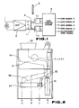
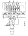
- An embodiment of this invention shown in Fig. 1 comprises a rectangular wave oscillation circuit 1, a primary or oscillation coil L1 and two receiving or secondary coils L2 and L3.
- the output of the rectangular wave oscillation circuit 1 is applied to the oscillation coil L1 through an amplifier 2.
- the oscillation coil L1 is disposed on one side of a coin passage 4 while receiving coils L2 and L3 are disposed on the other side to oppose the oscillation coil L1.
- the oscillation coil L1 is excited by a rectangular wave signal outputted by the rectangular wave oscillation circuit 1 to vary the mutual inductance M1 between the oscillation coil L1 and the receiving coil L2 and the mutual inductance M2 between the oscillation coil L1 and the receiving coil L3 caused by the passage of a coin 3 to be judged through the coin passage 4, so that signals for judging whether the coin is genuine or counterfeit are induced in the receiving coils L2 and L3.
- the outputs of the receiving coils L2 and L3 are applied to a coin judging circuit 5 which in response to the outputs of the receiving coils L2 and L3 judges whether the coin 3 is genuine or counterfeit as well as the type of the coin 3.
- the coin judging circuit 5 produces coin signals A, B, C or D representing the type of the coin 3 whereas when the coin is counterfeit, the circuit 5 produces a counterfeit coin signal.
- the detail of the coin judging circuit 5 will be described later.
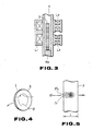
- the coin 3 inserted into a slot 30 drops on a rail 4a and then passes through the coin passage 4 between the oscillation coil L1 and the receiving coils L2 and L3 while rolling downward along the inclined rail 4a.
- the solenoid coil 31 is energized by the counterfeit coin signal outputted from the coin judging circuit 5 such that the gate 32 will guide the coin 3 to a counterfeit coin passage, not shown, whereas when the coin 3 is genuine, the gate 32 is controlled to guide the judged coin 3 onto a rail 33.
- the genuine coins guided on rail 33 are classified into coins A, B, C, and D by a classifying solenoid coil 34 energized by a signal outputted by the coin judging circuit 5 and representing the type of the coins.
- the coin sorting apparatus described above is designed to sort genuine coins of four types, the apparatus can be constructed to judge coins of any number of types.
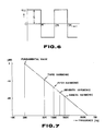
- the oscillation coil L1 is disposed on one side of the coin passage 4, and the receiving coils L2 and L3 are disposcd on the opposite side to oppose the oscillation coil L1.
- the receiving coil L3 is mainly used to judge the material of the coin and the receiving coil L3 is disposed near the center of the genuine coin having the smallest outer diameter.
- the other receiving coil L2 is mainly used to judge the outer diameter of the coin. Therefore the receiving coil L2 is located near the periphery of the coin where the effect of the outer diameter of the genuine coin is significant.
- the oscillation coil L1 uses a core of pot shape, it is possible to use a drum shaped core like receiving coils L2 and L3.
- the eddy current i caused by the electromotive force e is expressed by when R represents the resistance of a current path.
- Fig. 5 is an enlarged sectional view of a portion of the coin 3 and diagrammatically shows the skin effect.
- the eddy current produced by the flux ⁇ flows in the direction from the front side to the reverse side.
- a direct current flows in the coin 3
- an electric current flows though the coin 3 uniformly with respect to the section thereof.
- an alternating current flows in the coin 3
- an electric current does not flow uniformly through the coin 3 with respect to the section thereof, but flows more in the surface and decreases toward the center. This phenomenon is called the skin effect.
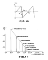
- This invention is based on a unique utilization of this phenomenon. More particularly, the oscillation coil L1 is excited by a rectangular wave consisting of a fundamental wave and a plurality of harmonic waves and the judgment of the coin is made by utilizing these harmonic waves.
- Fig. 7 is a frequency spectrum showing theoretical magnitudes of various harmonic components contained in a rectangular wave shown in Fig. 6 also containing a fundamental wave having a frequency of 20 kHz.
- nonsinusoidal waves as a triangular wave and a saw tooth wave also contain many harmonic components.
- Fig. 9 is a frequency spectrum showing theoretical magnitudes of harmonics components contained in a triangular wave shown in Fig. 8 and having a fundamental wave having a frequency of 20 kHz.
- Fig. 11 shows a frequency spectrum of a saw tooth wave shown in Fig. 10.
- Fig. 14 shows the detail of the configuration of the embodiment shown in Fig. 1.
- a resonance circuit constituted by a resistor R1 and a capacitor C1 is connected across the receiving coil L2 and a similar resonance circuit including a resistor R2 and a capacitor C2 is connected across the receiving coil L3.
- These resonance circuits have filter effects having resonance points f01 and f02 shown in Fig. 15.
- the resonance point f01 is located between the fundamental frequency 20 kHz and the third harmonic 60 kHz and effective composite compositions corresponding to respective frequencies are derived out.
- the resonance point of frequency f02 is located between the frequencies of 9th harmonic 180 kHz and the 11th harmonic 220 kHz so that effective composite components corresponding to respective frequencies are derived out.
- the composite composition corresponding to the frequency f01 is used to examine or judge the material and thickness of the coin to be judged, whereas the composite component corresponding to the frequency f02 is used to judge the outer diameter of the coin.
- a composite wave as shown in Fig. 16 which is a resultant of the fundamental wave (low frequency) and the third harmonic (high frequency) appears across the receiving coil L2.
- a composite wave corresponding to the resultant of the 9th and 11th harmonics appears across the receiving coil L3.
- Composite waves appearing across the receiving coils L2 and L3 by the actions of the resonant circuits R1, C1 and R2, C2 are applied to low pass filters LPF(A) and LPF(B) respectively via amplifiers A2 and A3.
- Each of the signals passed through the low pass filters is an envelop signal shown in Fig. 18 obtained by demodulating (that is by removing carrier wave) modulated wave shown in Fig. 17.
- the signals are temporary stored in hold circuits HOLD(A) and HOLD(B) and then applied to comparators COM (A1-A4) and COM (B1-B4) respectively set with threshold values of respective coins produced by reference voltage circuits REF(A) and REF(B).
- a comparator corresponding to this coin produces a signal which is applied to one input of one of AND gate circuits AND(1-4), the other input being supplied with a gate signal outputted from a judging signal circuit 51.
- AND gate circuits AND(1-4) which produce genuine coin signals A, B, C and D. These signals control the genuine and counterfeit sorting solenoid coil 31 through a suitable control unit, for example, a central processing unit, so as to guide genuine coin to the genuine coin passage.
- a single oscillation coil L1 is excited by a nonsinusoidal alternating current generated by the rectangular wave oscillation circuit 1, the oscillation coil is coupled with two receiving coils L2 and L3, resonance frequencies thereof being selected to suitable frequencies by resonance circuits R1, C1 and R2, C2, and the coin is judged by the output voltages of the receiving coils L2 and L3.
- the material, thickness and outer diameter of the coin 3 can be judged by using only one oscillation circuit and a single oscillation coil.
- a clad coin 60 comprising a core 61 made of copper and nickel clads 62 and a copper coin having the same diameter and thickness as the clad coin 60 are taken as examples.
- the frequency of the fundamental wave is set in a range of 15-30 kHz and that the frequencies of the harmonic waves are set in a range of 45-90 kHz.
- the flux mainly interacts with the copper comprising the core of the clad coin and the percentage of attenuation resembles a curve of copper shown in Fig. 20.
- the harmonic waves result in a skin effect.
- oscillation coil L1 is excited by a rectangular wave oscillation circuit 1, and receiving coils L2 and L3 are connected to bandpass filters BPF(A) and BPF(B), respectively, constructed to pass frequencies fc1, fc2 and fc3, fc4 shown in Fig. 15.
- Signals outputted from these filters BPF(A) and BPF(B) have waveforms as shown in Fig. 16, from which a composite wave can be derived out.
- this modification operates in the same manner as the embodiments shown in Figs. 1 and 14.
- Fig. 24 shows a bandpass filter generally used.
- Fig. 25 shows still another embodiment of this invention in which two oscillation coils L1 and L1′ are excited by the same nonsinusoidal alternating current. As shown, oscillation coils L1 and L1′ are connected in series to be excited by the output of the rectangular wave oscillation circuit 1 via an amplifier 2. Receiving coils L2 and L3 are provided to couple with the oscillation coils L1 and L1′ respectively.
- Receiving coils L2 and L3 and capacitors C1 and C2 form resonance circuits and provide filter effects having resonance points f01 and f02 shown in Fig. 15 in the same manner as in the embodiment shown in Fig. ]4.
- signals produced by the receiving coils L2 and L3 are composed as shown in Fig. 16, meaning that the modification shown in Fig. 25 operates in the same manner as the embodiment shown in Figs. 1 and 14.
- Still another embodiment shown in Figs. 27 is constituted by a single oscillation coil L1 and a single receiving coil L2 opposing thereto.
- a plurality of bandpass filters BPF(1-n) are connected to the receiving coil L2 and the outputs of the bandpass filters BPF(1-n) are derived out through amplifiers A(1-n) respectively.
- the arrangement of the oscillation coil L1, the receiving coil L2 and the coin passage 4 is shown in Fig. 28.
- a rectangular wave oscillator is used to excite one or more primary coils, but nonsinusoidal waves other than the rectangular wave can be used so long as the nonsinusoidal wave contains desired harmonics of sufficient levels.
Abstract
Description
- This invention relates to a method and apparatus for sorting coins utilized in automatic vending machines, money exchange machines; service devices, etc., and more particularly to an electronic coin sorting apparatus which sorts coins by electronic means.
- There have been used two types of coin sorting apparatus. The first type is mechanical sorting apparatus in which the characteristics of coins are mechanically examined or judged for sorting, and the other type is electrical sorting apparatus in which the characteristics of the coins are detected by electronic means and the coins are sorted according to the detected outputs. Since the electronic coin sorting apparatus has a high sorting accuracy and can be miniaturized, this type of the sorting apparatus have been used widely.
- An electronic coin sorting apparatus generally constructed such that a primary coil excited by a signal of a definite frequency is disposed on one side of a coin passage, a secondary coil electromagnetically coupled with the primary coil is disposed on the other side of the coin passage, an attenuatting voltage signal generated by the secondary coil which is generated at the time of passing the coin is used to judge whether the coin is genuine or counterfeit, and the reliability of the coin is examined according to a result of judgment.
- It has also been proposed an electronic coin sorting apparatus wherein a plurality of pairs of coin detecting coils each comprising a primary oscillation coil and a secondary receiving coil are provided for detecting the material, thickness, external diameter or the like of the coin. Further, according to one method, signals of different frequencies are applied to different primary coils while in another method the primary coil itself acts as an element of an oscillation circuit so as to constitute a self-oscillation circuit. In both methods, a plurality of discrete driving circuits or oscillation circuits are provided for exciting respective primary coils.
- U.S. Pat. No. 3870137 discloses a coin sorting apparatus, wherein at least two electromagnetic fields having different frequencies are provided for judging the characteristics of the coin by the action of these electromagnetic fields. Respective electromagnetic fields have different oscillation circuits to be applied with different check frequencies so as to check whether the diameter and thickness of the coin are included in predetermined ranges by using the interaction between the coin and the different check frequencies. When the coin satisfies the check standard at least two different frequencies, the coin is judged acceptable.
- With these prior arts, however, to improve the coin sorting accuracy, it is necessary to use plurality of oscillation circuits and oscillation coils, so that the number of component parts and hence the manufacturing cost are increased. Moreover, since respective oscillation coils are excited by different frequencies, interference between these coils are liable to occur. To avoid the interference, it is necessary to increase the distance between the coils which makes long the coin passage.
- In the prior art coin sorting apparatus, for example, that described in U.S. Pat. No. 3870137, for the purpose of providing interaction with the coin, a plurality of exciting coils respectively excited by low and high frequencies are used. Consequently where clad coins are to be examined wherein this sheets of nickel and copper are superposed as in 10 cent, 25 cent and 50 cent coins, for the purpose of checking characteristics of respective materials, it is necessary to use a plurality of oscillation circuits and oscillation coils. As a consequence, the sorting circuit also become complicated. Furthermore, for the purpose of judging the material and thickness of the coin, independent low frequency oscillation circuit and high frequency oscillation circuit are necessary for obtaining discrete mutual reactions so that the judging means becomes complicated in construction. Moreover, such judging means can be used for only specific type of coins.
- Accordingly, it is an object of this invention to provide a novel method for sorting coins, and coin sorting apparatus having a small size, and inexpensive simple construction.
- According to one aspect of this invention, there is provided a method of sorting coins comprising the steps of passing coins to be sorted near a primary or oscillation coil excited by an exciting signal containing a plurality of harmonic component and sorting the coins in accordance with a received signal induced in a receiving coil electromagnetically coupled with the oscillation coil, the received signal containing at least two harmonic components.
- The exciting signal may be a rectangular wave or a nonsinusoidal wave. A resonance circuit or a bandpass filter selectively passing a signal in a specific frequency bandwidth may be provided. A judging circuit may be connected to the receiving coil for judging whether the coil is genuine or counterfeit, and the type of coins and the material, configuration and the outer diameter of the coin. The coin is sorted by the output of the judging circuit.
- In accordance with another aspect of this invention, there is provided a coin sorting apparatus comprising an oscillation coil excited by an exciting signal containing a plurality of harmonic component, a receiving coil electromagnetically coupled with the oscillation coil, a coin passage for passing the coin near the oscillation coil, means for extracting a composite signal based on at least two harmonic components from a received signal induced in the receiving coil as a result of passing the coin through the coin passage, and means for sorting the coin based on the composite signal extracted by the extracting means.
- The exciting signal may be a signal having a rectangular wave form. The oscillation coil may be a single coil and one or two receiving coils may be electromagnetically coupled therewith. Alternatively two oscillation coils are connected in series and two receiving coils coupled with two oscillation coils respectively can be used.
- In the accompanying drawings:
- Fig. 1 is a block diagram showing one embodiment of this invention;
- Fig. 2 is a view showing the general construction of the coin sorting apparatus according to this invention;
- Fig. 3 shows the arrangement of the primary or oscillation coil and the receiving coil of the apparatus shown in Fig. 2;
- Fig. 4 is a perspective view of a coin useful to explain an eddy current loss;
- Fig. 5 is a diagram for explaining a skin effect;
- Fig. 6 shows one example of a rectangular wave;
- Fig. 7 is a spectrum diagram showing the harmonic components of the rectangular wave;
- Fig. 8 shows one example of a triangular wave;
- Fig. 9 is a spectrum diagram showing the harmonic components of the triangular wave shown in Fig. 8;
- Fig. 10 shows one example of a saw tooth wave;
- Fig. 11 is a spectrum diagram showing the harmonic components of the saw tooth wave shown in Fig. 10;
- Fig. 12 shows the waveform of a voltage impressed across the oscillation coil utilized in this embodiment;
- Fig. 13 is a spectrum diagram showing the harmonic components of the voltage shown in Fig. 12;
- Fig. 14 is a block diagram showing the detail of this embodiment;
- Fig. 15 is a spectrum diagram useful to explain the operation of the circuits shown in Fig. 14;
- Fig. 16, 17 and 18 are waveforms useful to explain the operation of the circuits shown in Fig. 14;
- Fig. 19 is a vertical sectional view of a coin that can be judged according to this invention;
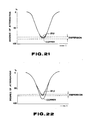
- Fig. 20, 21 and 22 are graphs showing the effect of judgment;
- Fig. 23 is a block diagram showing another embodiment of this invention;
- Fig. 24 is a block diagram showing one example of a bandpass filter utilized in the embodiment shown in Fig. 23;
- Fig. 25 is a block diagram showing still another embodiment of this invention;
- Fig. 26 is a vertical sectional view showing one example of the coil arrangement of the embodiment shown in Fig. 25;
- Fig. 27 is a block diagram showing yet another embodiment of this invention; and
- Fig. 28 is a vertical sectional view showing one example of the coil arrangement of the emboidment shown in Fig. 27.
- An embodiment of this invention shown in Fig. 1 comprises a rectangular
wave oscillation circuit 1, a primary or oscillation coil L₁ and two receiving or secondary coils L₂ and L₃. - The output of the rectangular
wave oscillation circuit 1 is applied to the oscillation coil L₁ through anamplifier 2. The oscillation coil L₁ is disposed on one side of acoin passage 4 while receiving coils L₂ and L₃ are disposed on the other side to oppose the oscillation coil L₁. - The oscillation coil L₁ is excited by a rectangular wave signal outputted by the rectangular
wave oscillation circuit 1 to vary the mutual inductance M₁ between the oscillation coil L₁ and the receiving coil L₂ and the mutual inductance M₂ between the oscillation coil L₁ and the receiving coil L₃ caused by the passage of acoin 3 to be judged through thecoin passage 4, so that signals for judging whether the coin is genuine or counterfeit are induced in the receiving coils L₂ and L₃. - The outputs of the receiving coils L₂ and L₃ are applied to a
coin judging circuit 5 which in response to the outputs of the receiving coils L₂ and L₃ judges whether thecoin 3 is genuine or counterfeit as well as the type of thecoin 3. Thus, when thecoin 3 is genuine thecoin judging circuit 5 produces coin signals A, B, C or D representing the type of thecoin 3 whereas when the coin is counterfeit, thecircuit 5 produces a counterfeit coin signal. The detail of thecoin judging circuit 5 will be described later. - In Fig. 2, the
coin 3 inserted into aslot 30 drops on arail 4a and then passes through thecoin passage 4 between the oscillation coil L₁ and the receiving coils L₂ and L₃ while rolling downward along theinclined rail 4a. - While passing through the
passage 4 between coils L₁, L₂ and L₃, the material, thickness and the outer diameter of thecoin 3 are judged by thecoin judging circuit 5 and agate 32 for separating genuine coins from counterfeit coins is controlled by asolenoid coil 31. - Thus, when the
coin 3 is counterfeit, thesolenoid coil 31 is energized by the counterfeit coin signal outputted from thecoin judging circuit 5 such that thegate 32 will guide thecoin 3 to a counterfeit coin passage, not shown, whereas when thecoin 3 is genuine, thegate 32 is controlled to guide the judgedcoin 3 onto arail 33. - The genuine coins guided on
rail 33 are classified into coins A, B, C, and D by a classifyingsolenoid coil 34 energized by a signal outputted by thecoin judging circuit 5 and representing the type of the coins. - Although the coin sorting apparatus described above is designed to sort genuine coins of four types, the apparatus can be constructed to judge coins of any number of types.
- As shown in Fig. 3, the oscillation coil L₁ is disposed on one side of the
coin passage 4, and the receiving coils L₂ and L₃ are disposcd on the opposite side to oppose the oscillation coil L₁. - In this embodiment, the receiving coil L₃ is mainly used to judge the material of the coin and the receiving coil L₃ is disposed near the center of the genuine coin having the smallest outer diameter.
- The other receiving coil L₂ is mainly used to judge the outer diameter of the coin. Therefore the receiving coil L₂ is located near the periphery of the coin where the effect of the outer diameter of the genuine coin is significant.
- Although the oscillation coil L₁ uses a core of pot shape, it is possible to use a drum shaped core like receiving coils L₂ and L₃.
- The principle of judging the coin according to this invention will now be described. As shown in Fig. 4, when varying flux φ produced by the oscillation coil L₁ passes through the
coin 3 made of electric conductor, eddy current i is induced in thecoin 3. The eddy current causes an eddy current loss in the form of Joule heat due to resistance of the coin. - Denoting the rate of variation of flux φ linking the
coin 3 by f and the maximum density of the flux φ by Bm, the magnitude of the electromotive force e induced in thecoin 3 is expressed by
- The eddy current i caused by the electromotive force e is expressed by

- Consequently, the eddy current loss P can be expressed by the following equation

- This equation shows that the eddy current loss is proportional to the square of the frequency of the varying flux φ. Due to this eddy current loss, the flux produced by the oscillation coil is attenuated when the flux links the receiving coils. The degree of loss of flux φ caused by the eddy current loss differs dependent upon the material, that is, the specific resistance of metal used to proper coins. For example, the specific resistance at 20°C of copper, aluminum, nickel and iron are 1.673, 2.6548, 6.84 and 9.71 microohm cm, respectively.
- The eddy current causes a skin effect. Fig. 5 is an enlarged sectional view of a portion of the
coin 3 and diagrammatically shows the skin effect. In Fig. 5, the eddy current produced by the flux φ flows in the direction from the front side to the reverse side. When a direct current flows in thecoin 3, an electric current flows though thecoin 3 uniformly with respect to the section thereof. When an alternating current flows in thecoin 3, an electric current does not flow uniformly through thecoin 3 with respect to the section thereof, but flows more in the surface and decreases toward the center. This phenomenon is called the skin effect. - Referring to Fig. 5, in which a section of the coin is divided into small segments, from electric current i′n flowing each segment, magnetic flux φ′n caused by the current i′n and the number of flux linkage of φ′n, it is found that the number of flux linkage is increased toward the center of the section of the coin. Therefore, increased electromotive force is great and the electric current is difficult to flow in the center.
- This phenomenon is more conspicuous when the frequency of the applied alternative current is higher. When the frequency is very high, most of the electric current flows in the surface of the coin.
- On the other hand, there is magnetic shielding effect. When a coin of magnetic substance such as iron passes between the oscillation coil L₁ and the receiving coils L₂ and L₃, the magnetic flux produced by the oscillation coil L₁ is absorbed in the coin, and the receiving coils L₂ and L₃ receive reduce flux.
- It is known that the skin effect and the magnetic shielding effect generate simultaneously and these effect cooperate the act.
- This invention is based on a unique utilization of this phenomenon. More particularly, the oscillation coil L₁ is excited by a rectangular wave consisting of a fundamental wave and a plurality of harmonic waves and the judgment of the coin is made by utilizing these harmonic waves.
- Fig. 7 is a frequency spectrum showing theoretical magnitudes of various harmonic components contained in a rectangular wave shown in Fig. 6 also containing a fundamental wave having a frequency of 20 kHz.
- In addition to a rectangular wave pulse, such nonsinusoidal waves as a triangular wave and a saw tooth wave also contain many harmonic components.
- Fig. 9 is a frequency spectrum showing theoretical magnitudes of harmonics components contained in a triangular wave shown in Fig. 8 and having a fundamental wave having a frequency of 20 kHz. In the same manner, Fig. 11 shows a frequency spectrum of a saw tooth wave shown in Fig. 10.
- The harmonic components of the rectangular wave, the triangular wave and the saw tooth wave which are not sinusoidal can be explained by Fourier series.
- Comparing Figs. 7, 9 and 11 with each other, the maximum value of the harmonic waves contained in a nonsinusoidal alternating current decreases as the order of the harmonic becomes higher but the rate of attenuation is great as the degree of discontinuation of the waveform is small. The waveform useful to this invention is one whose degree of discontinuation is large. Accordingly, comparison of Figs. 7, 9 and 11 shows that a rectangular wave shown in Fig. 6 is most effective.
- From experiment, it was found that with the configuration shown in Fig. 1, the voltage waveform across the oscillation coil L₁ is the waveform shown in Fig. 12. The frequency spectrum of the voltage induced in the receiving coils L₂ and L₃ is shown in Fig. 13 which contains harmonic components useful to this invention.
- Fig. 14 shows the detail of the configuration of the embodiment shown in Fig. 1. In Fig. 14, a resonance circuit constituted by a resistor R₁ and a capacitor C₁ is connected across the receiving coil L₂ and a similar resonance circuit including a resistor R₂ and a capacitor C₂ is connected across the receiving coil L₃.
- These resonance circuits have filter effects having resonance points f₀₁ and f₀₂ shown in Fig. 15. As shown in Fig. 15, the resonance point f₀₁ is located between the
fundamental frequency 20 kHz and the third harmonic 60 kHz and effective composite compositions corresponding to respective frequencies are derived out. The resonance point of frequency f₀₂ is located between the frequencies of 9th harmonic 180 kHz and the 11th harmonic 220 kHz so that effective composite components corresponding to respective frequencies are derived out. The composite composition corresponding to the frequency f₀₁ is used to examine or judge the material and thickness of the coin to be judged, whereas the composite component corresponding to the frequency f₀₂ is used to judge the outer diameter of the coin. When thecoin 3 passes through the coin passage between the coils L₁, L₂ and L₃ the resultant wave form appearing across receiving coils L₂ and L₃ is as shown in Fig. 16. - By the action of the resonance circuit R₁, C₁, a composite wave as shown in Fig. 16 which is a resultant of the fundamental wave (low frequency) and the third harmonic (high frequency) appears across the receiving coil L₂. In the same manner, a composite wave corresponding to the resultant of the 9th and 11th harmonics appears across the receiving coil L₃.
- Composite waves appearing across the receiving coils L₂ and L₃ by the actions of the resonant circuits R₁, C₁ and R₂, C₂ are applied to low pass filters LPF(A) and LPF(B) respectively via amplifiers A₂ and A₃. Each of the signals passed through the low pass filters is an envelop signal shown in Fig. 18 obtained by demodulating (that is by removing carrier wave) modulated wave shown in Fig. 17. After passing through the low pass filters LPF(A) and LPF(B), the signals are temporary stored in hold circuits HOLD(A) and HOLD(B) and then applied to comparators COM (A₁-A₄) and COM (B₁-B₄) respectively set with threshold values of respective coins produced by reference voltage circuits REF(A) and REF(B). When the
coin 3 is judged as genuine, a comparator corresponding to this coin produces a signal which is applied to one input of one of AND gate circuits AND(1-4), the other input being supplied with a gate signal outputted from a judgingsignal circuit 51. AND gate circuits AND(1-4) which produce genuine coin signals A, B, C and D. These signals control the genuine and counterfeitsorting solenoid coil 31 through a suitable control unit, for example, a central processing unit, so as to guide genuine coin to the genuine coin passage. - As above described according to this embodiment, a single oscillation coil L₁ is excited by a nonsinusoidal alternating current generated by the rectangular
wave oscillation circuit 1, the oscillation coil is coupled with two receiving coils L₂ and L₃, resonance frequencies thereof being selected to suitable frequencies by resonance circuits R₁, C₁ and R₂, C₂, and the coin is judged by the output voltages of the receiving coils L₂ and L₃. Thus it is possible to judge the material, thickness and outer diameter of thecoin 3 by using only one oscillation circuit and a single oscillation coil. - When a prior art apparatus utilizing a single frequency is used to judge US 5c, 10c and 25c coins each comprising a core of copper and outer layers of nickel as shown in Fig. 19 (that is so-called a clad coin), and a coin made of copper only, the characteristic of copper appears as shown in Fig. 21 thus failing to descriminate mere copper coins from clad coins.
- With the apparatus of this invention, the judged characteristics of the coins become as shown in Fig. 22. Thus the difference between two curves becomes larger than that shown in Fig. 21 which makes accurate judging.
- More particularly, a
clad coin 60 comprising a core 61 made of copper and nickel clads 62 and a copper coin having the same diameter and thickness as theclad coin 60 are taken as examples. Suppose now that the frequency of the fundamental wave is set in a range of 15-30 kHz and that the frequencies of the harmonic waves are set in a range of 45-90 kHz. Then in the low frequency range of 15-30 kHz, the flux mainly interacts with the copper comprising the core of the clad coin and the percentage of attenuation resembles a curve of copper shown in Fig. 20. However, the harmonic waves result in a skin effect. By the resultant function of these effects identification of a clad coin and a copper coin can be made readily as shown in Fig. 22. As the frequency of the AC exciting field generated by the oscillation coil L₁ increases, the skin effect caused by the eddy current loss becomes remarkable. In the case of a coin as shown in Fig. 19 the skin effect concentrates in the clads, which is different from that appearing in the surface of copper. As a consequence the copper coin can be discriminated from the clad coin as shown in Fig. 22. - Another embodiment of this invention is shown in Fig. 23. In this embodiment, oscillation coil L₁ is excited by a rectangular
wave oscillation circuit 1, and receiving coils L₂ and L₃ are connected to bandpass filters BPF(A) and BPF(B), respectively, constructed to pass frequencies fc₁, fc₂ and fc₃, fc₄ shown in Fig. 15. Signals outputted from these filters BPF(A) and BPF(B) have waveforms as shown in Fig. 16, from which a composite wave can be derived out. As above described, this modification operates in the same manner as the embodiments shown in Figs. 1 and 14. - Fig. 24 shows a bandpass filter generally used.
- Fig. 25 shows still another embodiment of this invention in which two oscillation coils L₁ and L₁′ are excited by the same nonsinusoidal alternating current. As shown, oscillation coils L₁ and L₁′ are connected in series to be excited by the output of the rectangular
wave oscillation circuit 1 via anamplifier 2. Receiving coils L₂ and L₃ are provided to couple with the oscillation coils L₁ and L₁′ respectively. - Receiving coils L₂ and L₃ and capacitors C₁ and C₂ form resonance circuits and provide filter effects having resonance points f₀₁ and f₀₂ shown in Fig. 15 in the same manner as in the embodiment shown in Fig. ]4. As a consequence signals produced by the receiving coils L₂ and L₃ are composed as shown in Fig. 16, meaning that the modification shown in Fig. 25 operates in the same manner as the embodiment shown in Figs. 1 and 14.
- An actual construction of the oscillation coils L₁ and L₁′, the receiving coils L₂ and L₃ and the
coin passage 4 are shown in Fig. 26. - Still another embodiment shown in Figs. 27 is constituted by a single oscillation coil L₁ and a single receiving coil L₂ opposing thereto. As shown in Fig. 27, a plurality of bandpass filters BPF(1-n) are connected to the receiving coil L₂ and the outputs of the bandpass filters BPF(1-n) are derived out through amplifiers A(1-n) respectively. The arrangement of the oscillation coil L₁, the receiving coil L₂ and the
coin passage 4 is shown in Fig. 28. - In the foregoing embodiments a rectangular wave oscillator is used to excite one or more primary coils, but nonsinusoidal waves other than the rectangular wave can be used so long as the nonsinusoidal wave contains desired harmonics of sufficient levels.
- It should be understood that the invention is not limited to specific embodiments described above, and that many changes and modification can be made within the true spirit and scope of the invention as defined in the appended claims.
Claims (12)
passing coins to be sorted near an oscillation coil excited by an exciting signal containing a plurality of harmonic components, and
sorting said coins in accordance with a received signal produced by a receiving coil electromagnetically coupled with said oscillation coil, said signal containing at least two harmonic components.
passing said coins near an oscillation coil excited by a nonsinusoidal alternating current;
generating a received signal in a receiving coil electromagnetically coupled with said oscillation coil;
deriving out from said received signal a first signal corresponding to a composite signal of at least two adjacent harmonic components, and a second signal corresponding to a composite signal of at least two other harmonic signals;
judging whether the coins are genuine or counterfeit and type of said coins based on said first and second signals; and
sorting said coins in accordance with a result of judgment.
an oscillation coil excited by an exciting signal containing a plurality of harmonic components:
a receiving coil electromagnetically coupled with said oscillation coil;
a coin passage for passing said coin near said oscillation coil,
means for extracting a signal based on at least two harmonic components from a received signal generated in said receiving coil as a result of passing said coin through said coin passage; and
means for sorting said coin based on said signal extracted by said extracting means.
a coin passage;
an oscillation coil disposed on one side of said coin passage and excited by a nonsinusoidal alternating current;
first and second receiving coils disposed on the other side of said coin passage and electromagnetically coupled with said oscillation coil;
first extracting means connected to said first receiving coil for simultaneously extracting at least two harmonic components from a signal received by said first receiving coil to produce a composite signal of said two extracted harmonic components;
second extracting means connected to said second receiving coil for simultaneously extracting at least two other harmonic components from a signal received by said second receiving coil to produce a composite signal of said other two extracted harmonic components;
judging means responsive to output signals of said first and second extracting means for judging whether coins are genuine or counterfeit and type of said coins passing through said coin passage and
sorting means for sorting said coins passing through said coin passage in accordance with an output of said judging means.
a coin passage;
first and second oscillation coils disposed on one side of said coin passage and excited by the same nonsinusoidal alternating current;
first and second receiving coils which are electron magnetically coupled with said first and second oscillation coils respectively;
first extracting means connected to said first receiving coil for simultaneously extracting at least two harmonic components from a signal received by said first receiving coil to produce a composite signal of said two harmonic components;
second extracting means connected to said second receiving coil for simultaneously extracting at least two harmonic components from a signal received by said second receiving coil to produce a composite signal of said two harmonic components;
judging means responsive to output signals of said first and second extracting means for judging whether the coins are genuine or counterfeit and type of said coins passing through said coin passage, and
sorting means for sorting said coins passing through said coin passage.
a coin passage;
a single oscillation coil disposed on one side of said coin passage and excited by a nonsinusoidal alternating current;
a single receiving coil disposed on the other side of said coin passage and electromagnetically coupled with said oscillation coil;
extracting means connected to said receiving coil for deriving out a composite signal of at least two harmonic components;
judging means responsive to an output signal of said extracting means for judging whether coins are genuine or counterfeit and type of said coins passing through said coin passage; and
sorting means responsive to an output signal of said judging means for sorting said coins passing through said coin passage.
Applications Claiming Priority (2)
| Application Number | Priority Date | Filing Date | Title |
|---|---|---|---|
| JP63079531A JP2567654B2 (en) | 1988-03-31 | 1988-03-31 | Coin sorting method and device |
| JP79531/88 | 1988-03-31 |
Publications (3)
| Publication Number | Publication Date |
|---|---|
| EP0336018A2 true EP0336018A2 (en) | 1989-10-11 |
| EP0336018A3 EP0336018A3 (en) | 1989-11-29 |
| EP0336018B1 EP0336018B1 (en) | 1998-05-20 |
Family
ID=13692573
Family Applications (1)
| Application Number | Title | Priority Date | Filing Date |
|---|---|---|---|
| EP88121926A Expired - Lifetime EP0336018B1 (en) | 1988-03-31 | 1988-12-31 | Method and apparatus for sorting coins |
Country Status (6)
| Country | Link |
|---|---|
| US (1) | US4971187A (en) |
| EP (1) | EP0336018B1 (en) |
| JP (1) | JP2567654B2 (en) |
| KR (1) | KR920002855B1 (en) |
| CA (1) | CA1332965C (en) |
| DE (1) | DE3856188T2 (en) |
Cited By (9)
| Publication number | Priority date | Publication date | Assignee | Title |
|---|---|---|---|---|
| WO1991006928A1 (en) * | 1989-10-31 | 1991-05-16 | Paavo Lahtinen | Sorting mechanism for coins |
| WO1991017527A1 (en) * | 1990-05-10 | 1991-11-14 | Mars Incorporated | Method and apparatus for testing coins |
| EP0886247A2 (en) | 1997-06-21 | 1998-12-23 | National Rejectors Inc. GmbH | Method and circuit for testing coins |
| EP1035519A1 (en) * | 1999-03-08 | 2000-09-13 | F. Zimmermann GmbH & Co. KG | Coin recognition device |
| EP1104920A1 (en) * | 1999-12-02 | 2001-06-06 | Glory Kogyo Kabushiki Kaisha | Method of and apparatus for identifying a coin |
| EP1286313A2 (en) * | 2001-08-16 | 2003-02-26 | National Rejectors, Inc. GmbH | Method and device for measuring the diameters of coins |
| EP1411480A2 (en) * | 2002-09-04 | 2004-04-21 | Dmitri Koroliouk | Method and device for validation of coins and counters |
| CN103258365A (en) * | 2012-02-10 | 2013-08-21 | 光荣株式会社 | Magnetic sensor for coin recognition |
| CN105264575A (en) * | 2013-05-31 | 2016-01-20 | 日本电产三协株式会社 | Apparatus for identifying coin-shaped detection object |
Families Citing this family (46)
| Publication number | Priority date | Publication date | Assignee | Title |
|---|---|---|---|---|
| GB2234619B (en) * | 1989-07-28 | 1993-04-14 | Mars Inc | Coin validators |
| US5542880A (en) * | 1990-05-14 | 1996-08-06 | Cummins-Allison Corp. | Coin handling system with shunting mechanism |
| US5507379A (en) * | 1990-05-14 | 1996-04-16 | Cummins-Allison Corp. | Coin handling system with coin sensor discriminator |
| US5630494A (en) * | 1995-03-07 | 1997-05-20 | Cummins-Allison Corp. | Coin discrimination sensor and coin handling system |
| US6363164B1 (en) | 1996-05-13 | 2002-03-26 | Cummins-Allison Corp. | Automated document processing system using full image scanning |
| US5579887A (en) * | 1995-06-15 | 1996-12-03 | Coin Acceptors, Inc. | Coin detection apparatus |
| US5782686A (en) * | 1995-12-04 | 1998-07-21 | Cummins-Allison Corp. | Disc coin sorter with slotted exit channels |
| US5865673A (en) * | 1996-01-11 | 1999-02-02 | Cummins-Allison Corp. | Coin sorter |
| GB2310070B (en) * | 1996-02-08 | 1999-10-27 | Mars Inc | Coin diameter measurement |
| US5997395A (en) * | 1998-03-17 | 1999-12-07 | Cummins-Allison Corp. | High speed coin sorter having a reduced size |
| US7635059B1 (en) | 2000-02-02 | 2009-12-22 | Imonex Services, Inc. | Apparatus and method for rejecting jammed coins |
| US8701857B2 (en) | 2000-02-11 | 2014-04-22 | Cummins-Allison Corp. | System and method for processing currency bills and tickets |
| SE521207C2 (en) * | 2001-03-22 | 2003-10-14 | Scan Coin Ind Ab | Device and method for separating coins where a variation in capacitance occurs between a sensor electrode and a surface of the coin when the coin is in transit |
| SE522752C2 (en) * | 2001-11-05 | 2004-03-02 | Scan Coin Ind Ab | Method of operating a coin discriminator and a coin discriminator where the influence on coil means is measured when coins are exposed to magnetic fields generated by coil means outside the coin |
| US6896118B2 (en) | 2002-01-10 | 2005-05-24 | Cummins-Allison Corp. | Coin redemption system |
| JP4022583B2 (en) * | 2002-03-11 | 2007-12-19 | 旭精工株式会社 | Coin selector |
| US6892871B2 (en) * | 2002-03-11 | 2005-05-17 | Cummins-Allison Corp. | Sensor and method for discriminating coins of varied composition, thickness, and diameter |
| US7743902B2 (en) | 2002-03-11 | 2010-06-29 | Cummins-Allison Corp. | Optical coin discrimination sensor and coin processing system using the same |
| US8171567B1 (en) | 2002-09-04 | 2012-05-01 | Tracer Detection Technology Corp. | Authentication method and system |
| US20040092222A1 (en) * | 2002-11-07 | 2004-05-13 | Bogdan Kowalczyk | Stationary head for a disc-type coin processing device having a solid lubricant disposed thereon |
| US8393455B2 (en) | 2003-03-12 | 2013-03-12 | Cummins-Allison Corp. | Coin processing device having a moveable coin receptacle station |
| ES2343730T3 (en) * | 2003-09-24 | 2010-08-09 | Scan Coin Ab | CURRENCY DISCRIMINATOR. |
| US9934640B2 (en) | 2004-09-15 | 2018-04-03 | Cummins-Allison Corp. | System, method and apparatus for repurposing currency |
| US8523641B2 (en) | 2004-09-15 | 2013-09-03 | Cummins-Allison Corp. | System, method and apparatus for automatically filling a coin cassette |
| US8602200B2 (en) | 2005-02-10 | 2013-12-10 | Cummins-Allison Corp. | Method and apparatus for varying coin-processing machine receptacle limits |
| WO2007044570A2 (en) | 2005-10-05 | 2007-04-19 | Cummins-Allison Corp. | Currency processing system with fitness detection |
| US7980378B2 (en) | 2006-03-23 | 2011-07-19 | Cummins-Allison Corporation | Systems, apparatus, and methods for currency processing control and redemption |
| JP4584194B2 (en) * | 2006-06-20 | 2010-11-17 | ローレル精機株式会社 | Discoid metal identification device |
| US8545295B2 (en) | 2010-12-17 | 2013-10-01 | Cummins-Allison Corp. | Coin processing systems, methods and devices |
| US9092924B1 (en) | 2012-08-31 | 2015-07-28 | Cummins-Allison Corp. | Disk-type coin processing unit with angled sorting head |
| JP2014182539A (en) * | 2013-03-19 | 2014-09-29 | Nippon Conlux Co Ltd | Coin identification device |
| GB2512289B (en) * | 2013-03-22 | 2018-12-26 | Ross Nedwell Jeremy | A device for determining the characteristic impedance spectrum of a token |
| DE202014011507U1 (en) | 2013-09-11 | 2021-07-20 | Blau Product Development Inc. | Device for detecting counterfeit or altered bars, coins or metal |
| CN104134269B (en) * | 2014-06-23 | 2017-07-07 | 江苏多维科技有限公司 | A kind of Detecting of coin system |
| US10685523B1 (en) | 2014-07-09 | 2020-06-16 | Cummins-Allison Corp. | Systems, methods and devices for processing batches of coins utilizing coin imaging sensor assemblies |
| US9916713B1 (en) | 2014-07-09 | 2018-03-13 | Cummins-Allison Corp. | Systems, methods and devices for processing coins utilizing normal or near-normal and/or high-angle of incidence lighting |
| US9501885B1 (en) | 2014-07-09 | 2016-11-22 | Cummins-Allison Corp. | Systems, methods and devices for processing coins utilizing near-normal and high-angle of incidence lighting |
| US9508208B1 (en) | 2014-07-25 | 2016-11-29 | Cummins Allison Corp. | Systems, methods and devices for processing coins with linear array of coin imaging sensors |
| US9430893B1 (en) | 2014-08-06 | 2016-08-30 | Cummins-Allison Corp. | Systems, methods and devices for managing rejected coins during coin processing |
| US10089812B1 (en) | 2014-11-11 | 2018-10-02 | Cummins-Allison Corp. | Systems, methods and devices for processing coins utilizing a multi-material coin sorting disk |
| US9875593B1 (en) | 2015-08-07 | 2018-01-23 | Cummins-Allison Corp. | Systems, methods and devices for coin processing and coin recycling |
| EP3203448B1 (en) | 2016-01-18 | 2023-06-07 | Sigma Metalytics LLC | Systems and methods for detecting fake or altered bullion, coins, and metal |
| US10181234B2 (en) | 2016-10-18 | 2019-01-15 | Cummins-Allison Corp. | Coin sorting head and coin processing system using the same |
| US10679449B2 (en) | 2016-10-18 | 2020-06-09 | Cummins-Allison Corp. | Coin sorting head and coin processing system using the same |
| ES2752214T3 (en) | 2017-07-11 | 2020-04-03 | Azkoyen Sa | Coin sensor |
| GB2607538B (en) | 2019-01-04 | 2023-05-17 | Cummins Allison Corp | Coin pad for coin processing system |
Citations (10)
| Publication number | Priority date | Publication date | Assignee | Title |
|---|---|---|---|---|
| DE2014023A1 (en) * | 1970-03-24 | 1971-10-07 | Nat Rejectors Gmbh | Device for testing the own shafts of metal disks |
| US3870137A (en) * | 1972-02-23 | 1975-03-11 | Little Inc A | Method and apparatus for coin selection utilizing inductive sensors |
| GB2029995A (en) * | 1978-09-15 | 1980-03-26 | H R Electronics Co | Metal detectors |
| DE2916123A1 (en) * | 1979-04-19 | 1980-10-30 | Walter Hanke Mechanische Werks | Coin size and composition discriminator - has sensor with two windings over coin channel connected to separate circuits |
| FR2466055A1 (en) * | 1979-07-17 | 1981-03-27 | Nippon Coinco Co Ltd | HIGH DISCRIMINATION ELECTRONIC DEVICE FOR SELECTING COINS IN AUTOMATIC DISTRIBUTOR EQUIPMENT |
| GB2069211A (en) * | 1980-02-06 | 1981-08-19 | Mars Inc | Coin testing apparatus |
| GB2096812A (en) * | 1981-02-18 | 1982-10-20 | Appliance Components Ltd | Validation of coins and tokens |
| JPS5860203A (en) * | 1981-10-05 | 1983-04-09 | Kubota Ltd | Method for identifying circular body |
| GB2107104A (en) * | 1981-09-22 | 1983-04-20 | Mars Inc | Coin identification |
| GB2160689A (en) * | 1984-04-27 | 1985-12-24 | Piper Instr Limited | Coin detection |
Family Cites Families (12)
| Publication number | Priority date | Publication date | Assignee | Title |
|---|---|---|---|---|
| US3059749A (en) * | 1959-12-16 | 1962-10-23 | Paradynamics Inc | Coin testing apparatus |
| US3506103A (en) * | 1968-06-11 | 1970-04-14 | Alexander Kuckens | Coin tester using electromagnetic resonant frequency |
| CH551056A (en) * | 1971-06-11 | 1974-06-28 | Berliner Maschinenbau Ag | PROCEDURE FOR TESTING METALLIC OBJECTS, IN PARTICULAR OF COINS. |
| GB1483192A (en) * | 1973-11-22 | 1977-08-17 | Mars Inc | Arrival sensor |
| JPS5296598A (en) * | 1976-02-10 | 1977-08-13 | Nippon Koinko Kk | Coin examining means for automatic vending machines |
| JPS537400A (en) * | 1976-07-09 | 1978-01-23 | Sanyo Jido Hanbaiki Kk | Coin selecting device |
| JPS57103587A (en) * | 1980-12-19 | 1982-06-28 | Kubota Ltd | Identification of circular object |
| GB8303587D0 (en) * | 1983-02-09 | 1983-03-16 | Chapman Cash Processing Ltd | Coin discriminating apparatus |
| JPS59221782A (en) * | 1983-05-31 | 1984-12-13 | アンリツ株式会社 | Coin selector |
| US4538719A (en) * | 1983-07-01 | 1985-09-03 | Hilgraeve, Incorporated | Electronic coin acceptor |
| JPH07120452B2 (en) * | 1986-08-12 | 1995-12-20 | グローリー工業株式会社 | Coin identification device in coin processing machine |
| US4901017A (en) * | 1987-08-28 | 1990-02-13 | Zinke Otto H | Gap-modified magnetic bridge device for fringing flux analysis |
-
1988
- 1988-03-31 JP JP63079531A patent/JP2567654B2/en not_active Expired - Fee Related
- 1988-12-29 US US07/290,473 patent/US4971187A/en not_active Expired - Lifetime
- 1988-12-31 DE DE3856188T patent/DE3856188T2/en not_active Expired - Fee Related
- 1988-12-31 EP EP88121926A patent/EP0336018B1/en not_active Expired - Lifetime
-
1989
- 1989-01-12 KR KR1019890000262A patent/KR920002855B1/en not_active IP Right Cessation
- 1989-01-16 CA CA000588345A patent/CA1332965C/en not_active Expired - Fee Related
Patent Citations (10)
| Publication number | Priority date | Publication date | Assignee | Title |
|---|---|---|---|---|
| DE2014023A1 (en) * | 1970-03-24 | 1971-10-07 | Nat Rejectors Gmbh | Device for testing the own shafts of metal disks |
| US3870137A (en) * | 1972-02-23 | 1975-03-11 | Little Inc A | Method and apparatus for coin selection utilizing inductive sensors |
| GB2029995A (en) * | 1978-09-15 | 1980-03-26 | H R Electronics Co | Metal detectors |
| DE2916123A1 (en) * | 1979-04-19 | 1980-10-30 | Walter Hanke Mechanische Werks | Coin size and composition discriminator - has sensor with two windings over coin channel connected to separate circuits |
| FR2466055A1 (en) * | 1979-07-17 | 1981-03-27 | Nippon Coinco Co Ltd | HIGH DISCRIMINATION ELECTRONIC DEVICE FOR SELECTING COINS IN AUTOMATIC DISTRIBUTOR EQUIPMENT |
| GB2069211A (en) * | 1980-02-06 | 1981-08-19 | Mars Inc | Coin testing apparatus |
| GB2096812A (en) * | 1981-02-18 | 1982-10-20 | Appliance Components Ltd | Validation of coins and tokens |
| GB2107104A (en) * | 1981-09-22 | 1983-04-20 | Mars Inc | Coin identification |
| JPS5860203A (en) * | 1981-10-05 | 1983-04-09 | Kubota Ltd | Method for identifying circular body |
| GB2160689A (en) * | 1984-04-27 | 1985-12-24 | Piper Instr Limited | Coin detection |
Non-Patent Citations (2)
| Title |
|---|
| HASLER MITTEILUNGEN, vol. 36, no. 4, December 1977, pages 106-112, Hasler AG, Bern, CH; F. PULFER: "Moderne Fahrkarten ausgabe-Automaten und ihre wichtigsten Baugruppen" * |
| PATENT ABSTRACTS OF JAPAN, vol. 7, no. 150 (P-207)[1295], 30 juin 1983; & JP-A-58 060 203 (KUBOTA TEKKO K.K.) 09-04-1983 * |
Cited By (16)
| Publication number | Priority date | Publication date | Assignee | Title |
|---|---|---|---|---|
| WO1991006928A1 (en) * | 1989-10-31 | 1991-05-16 | Paavo Lahtinen | Sorting mechanism for coins |
| WO1991017527A1 (en) * | 1990-05-10 | 1991-11-14 | Mars Incorporated | Method and apparatus for testing coins |
| US5341908A (en) * | 1990-05-10 | 1994-08-30 | Mars Incorporated | Method and apparatus for testing coins |
| EP0886247A2 (en) | 1997-06-21 | 1998-12-23 | National Rejectors Inc. GmbH | Method and circuit for testing coins |
| DE19726449A1 (en) * | 1997-06-21 | 1999-01-07 | Nat Rejectors Gmbh | Method and circuit arrangement for checking coins |
| DE19726449C2 (en) * | 1997-06-21 | 1999-04-15 | Nat Rejectors Gmbh | Method and circuit arrangement for checking coins |
| EP0886247A3 (en) * | 1997-06-21 | 1999-12-01 | National Rejectors Inc. GmbH | Method and circuit for testing coins |
| EP1035519A1 (en) * | 1999-03-08 | 2000-09-13 | F. Zimmermann GmbH & Co. KG | Coin recognition device |
| EP1104920A1 (en) * | 1999-12-02 | 2001-06-06 | Glory Kogyo Kabushiki Kaisha | Method of and apparatus for identifying a coin |
| EP1286313A2 (en) * | 2001-08-16 | 2003-02-26 | National Rejectors, Inc. GmbH | Method and device for measuring the diameters of coins |
| EP1286313A3 (en) * | 2001-08-16 | 2004-05-06 | National Rejectors, Inc. GmbH | Method and device for measuring the diameters of coins |
| EP1411480A2 (en) * | 2002-09-04 | 2004-04-21 | Dmitri Koroliouk | Method and device for validation of coins and counters |
| EP1411480A3 (en) * | 2002-09-04 | 2004-09-29 | Dmitri Koroliouk | Method and device for validation of coins and counters |
| CN103258365A (en) * | 2012-02-10 | 2013-08-21 | 光荣株式会社 | Magnetic sensor for coin recognition |
| CN103258365B (en) * | 2012-02-10 | 2016-08-17 | 光荣株式会社 | Magnetic sensor for coin recognition |
| CN105264575A (en) * | 2013-05-31 | 2016-01-20 | 日本电产三协株式会社 | Apparatus for identifying coin-shaped detection object |
Also Published As
| Publication number | Publication date |
|---|---|
| AU603274B2 (en) | 1990-11-08 |
| JP2567654B2 (en) | 1996-12-25 |
| CA1332965C (en) | 1994-11-08 |
| EP0336018B1 (en) | 1998-05-20 |
| KR920002855B1 (en) | 1992-04-06 |
| US4971187A (en) | 1990-11-20 |
| KR890015176A (en) | 1989-10-28 |
| EP0336018A3 (en) | 1989-11-29 |
| DE3856188D1 (en) | 1998-06-25 |
| DE3856188T2 (en) | 1998-12-03 |
| AU2772089A (en) | 1989-12-07 |
| JPH01251292A (en) | 1989-10-06 |
Similar Documents
| Publication | Publication Date | Title |
|---|---|---|
| US4971187A (en) | Method and apparatus for sorting coins utilizing coin-derived signals containing different harmonic components | |
| US4488116A (en) | Inductive coin sensor for measuring more than one parameter of a moving coin | |
| EP0057972B1 (en) | A device for detecting a metal strip embedded in paper | |
| KR890002334B1 (en) | Testing for coins | |
| US3870137A (en) | Method and apparatus for coin selection utilizing inductive sensors | |
| US5871075A (en) | Coin sorting machine | |
| US6257488B1 (en) | Magnetic detector for security document | |
| JPS57193884A (en) | Apparatus for and method of identifying coin | |
| EP1646014A3 (en) | Coin discrimination apparatus and method | |
| EP0897569B1 (en) | Magnetic particles, substrate comprising such particles, security document and method for detecting such particles | |
| JP3605274B2 (en) | Dry cell classification method and dry cell classification device | |
| US6640955B1 (en) | Coin inspection method and device | |
| US4226323A (en) | Precision coin analyzer for numismatic application | |
| JPH0614383B2 (en) | Coin inspection device | |
| JPH0428059Y2 (en) | ||
| JP2000187746A (en) | Coin selector | |
| CN113345154B (en) | Coin identification method and coin identification instrument | |
| JP2513562B2 (en) | Coin / metal material identification device | |
| JPS61262992A (en) | Coin selector | |
| US6556090B1 (en) | Oscillator circuit for a validator | |
| JPS61262990A (en) | Coin selector | |
| JPH06347561A (en) | Metal classification device | |
| EP0848355A1 (en) | Method and apparatus for detecting the presence of particles in a substrate | |
| JPH06101054B2 (en) | Coin sorter | |
| JPS5965389A (en) | Coin discriminator |
Legal Events
| Date | Code | Title | Description |
|---|---|---|---|
| PUAI | Public reference made under article 153(3) epc to a published international application that has entered the european phase |
Free format text: ORIGINAL CODE: 0009012 |
|
| PUAL | Search report despatched |
Free format text: ORIGINAL CODE: 0009013 |
|
| 17P | Request for examination filed |
Effective date: 19881231 |
|
| AK | Designated contracting states |
Kind code of ref document: A2 Designated state(s): DE ES FR GB IT SE |
|
| AK | Designated contracting states |
Kind code of ref document: A3 Designated state(s): DE ES FR GB IT SE |
|
| 17Q | First examination report despatched |
Effective date: 19910905 |
|
| APAU | Communication from the board of appeal sent |
Free format text: ORIGINAL CODE: EPIDOS OBAP |
|
| APCB | Communication from the board of appeal sent |
Free format text: ORIGINAL CODE: EPIDOS OBAPE |
|
| APCB | Communication from the board of appeal sent |
Free format text: ORIGINAL CODE: EPIDOS OBAPE |
|
| APAB | Appeal dossier modified |
Free format text: ORIGINAL CODE: EPIDOS NOAPE |
|
| GRAG | Despatch of communication of intention to grant |
Free format text: ORIGINAL CODE: EPIDOS AGRA |
|
| GRAH | Despatch of communication of intention to grant a patent |
Free format text: ORIGINAL CODE: EPIDOS IGRA |
|
| GRAH | Despatch of communication of intention to grant a patent |
Free format text: ORIGINAL CODE: EPIDOS IGRA |
|
| GRAA | (expected) grant |
Free format text: ORIGINAL CODE: 0009210 |
|
| AK | Designated contracting states |
Kind code of ref document: B1 Designated state(s): DE ES FR GB IT SE |
|
| PG25 | Lapsed in a contracting state [announced via postgrant information from national office to epo] |
Ref country code: ES Free format text: THE PATENT HAS BEEN ANNULLED BY A DECISION OF A NATIONAL AUTHORITY Effective date: 19980520 Ref country code: IT Free format text: LAPSE BECAUSE OF FAILURE TO SUBMIT A TRANSLATION OF THE DESCRIPTION OR TO PAY THE FEE WITHIN THE PRE;WARNING: LAPSES OF ITALIAN PATENTS WITH EFFECTIVE DATE BEFORE 2007 MAY HAVE OCCURRED AT ANY TIME BEFORE 2007. THE CORRECT EFFECTIVE DATE MAY BE DIFFERENT FROM THE ONE RECORDED.SCRIBED TIME-LIMIT Effective date: 19980520 |
|
| REF | Corresponds to: |
Ref document number: 3856188 Country of ref document: DE Date of ref document: 19980625 |
|
| ET | Fr: translation filed | ||
| PG25 | Lapsed in a contracting state [announced via postgrant information from national office to epo] |
Ref country code: SE Free format text: LAPSE BECAUSE OF FAILURE TO SUBMIT A TRANSLATION OF THE DESCRIPTION OR TO PAY THE FEE WITHIN THE PRESCRIBED TIME-LIMIT Effective date: 19980820 |
|
| PG25 | Lapsed in a contracting state [announced via postgrant information from national office to epo] |
Ref country code: GB Free format text: LAPSE BECAUSE OF NON-PAYMENT OF DUE FEES Effective date: 19981231 |
|
| PLBE | No opposition filed within time limit |
Free format text: ORIGINAL CODE: 0009261 |
|
| STAA | Information on the status of an ep patent application or granted ep patent |
Free format text: STATUS: NO OPPOSITION FILED WITHIN TIME LIMIT |
|
| 26N | No opposition filed | ||
| GBPC | Gb: european patent ceased through non-payment of renewal fee |
Effective date: 19981231 |
|
| PG25 | Lapsed in a contracting state [announced via postgrant information from national office to epo] |
Ref country code: FR Free format text: LAPSE BECAUSE OF NON-PAYMENT OF DUE FEES Effective date: 19990831 |
|
| REG | Reference to a national code |
Ref country code: FR Ref legal event code: ST |
|
| PG25 | Lapsed in a contracting state [announced via postgrant information from national office to epo] |
Ref country code: DE Free format text: LAPSE BECAUSE OF NON-PAYMENT OF DUE FEES Effective date: 19991001 |
|
| APAH | Appeal reference modified |
Free format text: ORIGINAL CODE: EPIDOSCREFNO |