EP0335688A2 - Light-emitting or receiving device, encapsulant for light-emitting or receiving element and the method for encapsulating thereof - Google Patents
Light-emitting or receiving device, encapsulant for light-emitting or receiving element and the method for encapsulating thereof Download PDFInfo
- Publication number
- EP0335688A2 EP0335688A2 EP89303104A EP89303104A EP0335688A2 EP 0335688 A2 EP0335688 A2 EP 0335688A2 EP 89303104 A EP89303104 A EP 89303104A EP 89303104 A EP89303104 A EP 89303104A EP 0335688 A2 EP0335688 A2 EP 0335688A2
- Authority
- EP
- European Patent Office
- Prior art keywords
- light
- emitting
- encapsulant
- liquid
- mold
- Prior art date
- Legal status (The legal status is an assumption and is not a legal conclusion. Google has not performed a legal analysis and makes no representation as to the accuracy of the status listed.)
- Granted
Links
- 238000000034 method Methods 0.000 title claims abstract description 25
- 239000008393 encapsulating agent Substances 0.000 title claims description 53
- 239000000203 mixture Substances 0.000 claims abstract description 47
- 239000007788 liquid Substances 0.000 claims abstract description 35
- 239000000178 monomer Substances 0.000 claims abstract description 30
- 229920000642 polymer Polymers 0.000 claims abstract description 19
- PYGSKMBEVAICCR-UHFFFAOYSA-N hexa-1,5-diene Chemical group C=CCCC=C PYGSKMBEVAICCR-UHFFFAOYSA-N 0.000 claims abstract description 7
- LFQSCWFLJHTTHZ-UHFFFAOYSA-N Ethanol Chemical compound CCO LFQSCWFLJHTTHZ-UHFFFAOYSA-N 0.000 claims description 19
- JKJWYKGYGWOAHT-UHFFFAOYSA-N bis(prop-2-enyl) carbonate Chemical compound C=CCOC(=O)OCC=C JKJWYKGYGWOAHT-UHFFFAOYSA-N 0.000 claims description 19
- 125000003118 aryl group Chemical group 0.000 claims description 11
- 125000001931 aliphatic group Chemical group 0.000 claims description 8
- QVGXLLKOCUKJST-UHFFFAOYSA-N atomic oxygen Chemical compound [O] QVGXLLKOCUKJST-UHFFFAOYSA-N 0.000 claims description 8
- 239000001301 oxygen Substances 0.000 claims description 8
- 229910052760 oxygen Inorganic materials 0.000 claims description 8
- 239000004215 Carbon black (E152) Substances 0.000 claims description 7
- 229930195733 hydrocarbon Natural products 0.000 claims description 7
- 150000002430 hydrocarbons Chemical class 0.000 claims description 7
- 230000000379 polymerizing effect Effects 0.000 claims description 7
- 239000011261 inert gas Substances 0.000 claims description 6
- 238000005266 casting Methods 0.000 claims description 5
- 230000003287 optical effect Effects 0.000 abstract description 5
- 239000000126 substance Substances 0.000 abstract description 5
- MTHSVFCYNBDYFN-UHFFFAOYSA-N diethylene glycol Chemical compound OCCOCCO MTHSVFCYNBDYFN-UHFFFAOYSA-N 0.000 description 21
- -1 diallyl compound Chemical class 0.000 description 20
- 239000003505 polymerization initiator Substances 0.000 description 15
- 239000004615 ingredient Substances 0.000 description 12
- 238000006116 polymerization reaction Methods 0.000 description 12
- LYCAIKOWRPUZTN-UHFFFAOYSA-N Ethylene glycol Chemical compound OCCO LYCAIKOWRPUZTN-UHFFFAOYSA-N 0.000 description 9
- DNIAPMSPPWPWGF-UHFFFAOYSA-N Propylene glycol Chemical compound CC(O)CO DNIAPMSPPWPWGF-UHFFFAOYSA-N 0.000 description 9
- 239000003822 epoxy resin Substances 0.000 description 9
- 229920000647 polyepoxide Polymers 0.000 description 9
- 239000003921 oil Substances 0.000 description 7
- WERYXYBDKMZEQL-UHFFFAOYSA-N butane-1,4-diol Chemical compound OCCCCO WERYXYBDKMZEQL-UHFFFAOYSA-N 0.000 description 6
- BVKZGUZCCUSVTD-UHFFFAOYSA-L Carbonate Chemical compound [O-]C([O-])=O BVKZGUZCCUSVTD-UHFFFAOYSA-L 0.000 description 5
- SYFOAKAXGNMQAX-UHFFFAOYSA-N bis(prop-2-enyl) carbonate;2-(2-hydroxyethoxy)ethanol Chemical compound OCCOCCO.C=CCOC(=O)OCC=C SYFOAKAXGNMQAX-UHFFFAOYSA-N 0.000 description 5
- 239000007795 chemical reaction product Substances 0.000 description 5
- 239000006082 mold release agent Substances 0.000 description 5
- 238000012719 thermal polymerization Methods 0.000 description 5
- BPXVHIRIPLPOPT-UHFFFAOYSA-N 1,3,5-tris(2-hydroxyethyl)-1,3,5-triazinane-2,4,6-trione Chemical compound OCCN1C(=O)N(CCO)C(=O)N(CCO)C1=O BPXVHIRIPLPOPT-UHFFFAOYSA-N 0.000 description 4
- XKRFYHLGVUSROY-UHFFFAOYSA-N Argon Chemical compound [Ar] XKRFYHLGVUSROY-UHFFFAOYSA-N 0.000 description 4
- 230000000052 comparative effect Effects 0.000 description 4
- 229920001519 homopolymer Polymers 0.000 description 4
- 238000004519 manufacturing process Methods 0.000 description 4
- QIWKUEJZZCOPFV-UHFFFAOYSA-N phenyl 2-methylprop-2-enoate Chemical compound CC(=C)C(=O)OC1=CC=CC=C1 QIWKUEJZZCOPFV-UHFFFAOYSA-N 0.000 description 4
- BWJUFXUULUEGMA-UHFFFAOYSA-N propan-2-yl propan-2-yloxycarbonyloxy carbonate Chemical compound CC(C)OC(=O)OOC(=O)OC(C)C BWJUFXUULUEGMA-UHFFFAOYSA-N 0.000 description 4
- DNIAPMSPPWPWGF-VKHMYHEASA-N (+)-propylene glycol Chemical compound C[C@H](O)CO DNIAPMSPPWPWGF-VKHMYHEASA-N 0.000 description 3
- YPFDHNVEDLHUCE-UHFFFAOYSA-N 1,3-propanediol Substances OCCCO YPFDHNVEDLHUCE-UHFFFAOYSA-N 0.000 description 3
- QCDWFXQBSFUVSP-UHFFFAOYSA-N 2-phenoxyethanol Chemical compound OCCOC1=CC=CC=C1 QCDWFXQBSFUVSP-UHFFFAOYSA-N 0.000 description 3
- VYZKQGGPNIFCLD-UHFFFAOYSA-N 3,3-dimethylhexane-2,2-diol Chemical compound CCCC(C)(C)C(C)(O)O VYZKQGGPNIFCLD-UHFFFAOYSA-N 0.000 description 3
- UHOVQNZJYSORNB-UHFFFAOYSA-N Benzene Chemical compound C1=CC=CC=C1 UHOVQNZJYSORNB-UHFFFAOYSA-N 0.000 description 3
- 239000002202 Polyethylene glycol Substances 0.000 description 3
- PRUUDNOIZWXFSZ-UHFFFAOYSA-N bicyclo[2.2.1]heptane-3,7-diol Chemical compound C1CC2C(O)CC1C2O PRUUDNOIZWXFSZ-UHFFFAOYSA-N 0.000 description 3
- 150000001875 compounds Chemical class 0.000 description 3
- VEIOBOXBGYWJIT-UHFFFAOYSA-N cyclohexane;methanol Chemical compound OC.OC.C1CCCCC1 VEIOBOXBGYWJIT-UHFFFAOYSA-N 0.000 description 3
- SZXQTJUDPRGNJN-UHFFFAOYSA-N dipropylene glycol Chemical compound OCCCOCCCO SZXQTJUDPRGNJN-UHFFFAOYSA-N 0.000 description 3
- XXMIOPMDWAUFGU-UHFFFAOYSA-N hexane-1,6-diol Chemical compound OCCCCCCO XXMIOPMDWAUFGU-UHFFFAOYSA-N 0.000 description 3
- VLKZOEOYAKHREP-UHFFFAOYSA-N n-Hexane Chemical compound CCCCCC VLKZOEOYAKHREP-UHFFFAOYSA-N 0.000 description 3
- SLCVBVWXLSEKPL-UHFFFAOYSA-N neopentyl glycol Chemical compound OCC(C)(C)CO SLCVBVWXLSEKPL-UHFFFAOYSA-N 0.000 description 3
- 229920001223 polyethylene glycol Polymers 0.000 description 3
- 229920000166 polytrimethylene carbonate Polymers 0.000 description 3
- 150000003254 radicals Chemical class 0.000 description 3
- 238000002834 transmittance Methods 0.000 description 3
- 239000008096 xylene Substances 0.000 description 3
- LPOUEJRGNSCACM-UHFFFAOYSA-N 2,4-dichlorocyclohexa-1,5-diene-1,4-dicarboxylic acid Chemical compound OC(=O)C1=C(Cl)CC(Cl)(C(O)=O)C=C1 LPOUEJRGNSCACM-UHFFFAOYSA-N 0.000 description 2
- OZAIFHULBGXAKX-UHFFFAOYSA-N 2-(2-cyanopropan-2-yldiazenyl)-2-methylpropanenitrile Chemical compound N#CC(C)(C)N=NC(C)(C)C#N OZAIFHULBGXAKX-UHFFFAOYSA-N 0.000 description 2
- IJGRMHOSHXDMSA-UHFFFAOYSA-N Atomic nitrogen Chemical compound N#N IJGRMHOSHXDMSA-UHFFFAOYSA-N 0.000 description 2
- UUAGPGQUHZVJBQ-UHFFFAOYSA-N Bisphenol A bis(2-hydroxyethyl)ether Chemical compound C=1C=C(OCCO)C=CC=1C(C)(C)C1=CC=C(OCCO)C=C1 UUAGPGQUHZVJBQ-UHFFFAOYSA-N 0.000 description 2
- VEXZGXHMUGYJMC-UHFFFAOYSA-M Chloride anion Chemical compound [Cl-] VEXZGXHMUGYJMC-UHFFFAOYSA-M 0.000 description 2
- BAPJBEWLBFYGME-UHFFFAOYSA-N Methyl acrylate Chemical compound COC(=O)C=C BAPJBEWLBFYGME-UHFFFAOYSA-N 0.000 description 2
- ATUOYWHBWRKTHZ-UHFFFAOYSA-N Propane Chemical compound CCC ATUOYWHBWRKTHZ-UHFFFAOYSA-N 0.000 description 2
- PPBRXRYQALVLMV-UHFFFAOYSA-N Styrene Chemical compound C=CC1=CC=CC=C1 PPBRXRYQALVLMV-UHFFFAOYSA-N 0.000 description 2
- 239000007983 Tris buffer Substances 0.000 description 2
- XTXRWKRVRITETP-UHFFFAOYSA-N Vinyl acetate Chemical compound CC(=O)OC=C XTXRWKRVRITETP-UHFFFAOYSA-N 0.000 description 2
- NIXOWILDQLNWCW-UHFFFAOYSA-N acrylic acid group Chemical group C(C=C)(=O)O NIXOWILDQLNWCW-UHFFFAOYSA-N 0.000 description 2
- 229910052786 argon Inorganic materials 0.000 description 2
- KKEYFWRCBNTPAC-UHFFFAOYSA-N benzene-dicarboxylic acid Natural products OC(=O)C1=CC=C(C(O)=O)C=C1 KKEYFWRCBNTPAC-UHFFFAOYSA-N 0.000 description 2
- 150000001732 carboxylic acid derivatives Chemical class 0.000 description 2
- 239000003795 chemical substances by application Substances 0.000 description 2
- 229920001577 copolymer Polymers 0.000 description 2
- ZQMIGQNCOMNODD-UHFFFAOYSA-N diacetyl peroxide Chemical compound CC(=O)OOC(C)=O ZQMIGQNCOMNODD-UHFFFAOYSA-N 0.000 description 2
- 238000005538 encapsulation Methods 0.000 description 2
- 150000002148 esters Chemical class 0.000 description 2
- FPYJFEHAWHCUMM-UHFFFAOYSA-N maleic anhydride Chemical compound O=C1OC(=O)C=C1 FPYJFEHAWHCUMM-UHFFFAOYSA-N 0.000 description 2
- XNGIFLGASWRNHJ-UHFFFAOYSA-N phthalic acid Chemical class OC(=O)C1=CC=CC=C1C(O)=O XNGIFLGASWRNHJ-UHFFFAOYSA-N 0.000 description 2
- 229920001083 polybutene Polymers 0.000 description 2
- 229920000098 polyolefin Polymers 0.000 description 2
- 229920005604 random copolymer Polymers 0.000 description 2
- 229920005989 resin Polymers 0.000 description 2
- 239000011347 resin Substances 0.000 description 2
- QDRKDTQENPPHOJ-UHFFFAOYSA-N sodium ethoxide Chemical compound [Na+].CC[O-] QDRKDTQENPPHOJ-UHFFFAOYSA-N 0.000 description 2
- GJBRNHKUVLOCEB-UHFFFAOYSA-N tert-butyl benzenecarboperoxoate Chemical compound CC(C)(C)OOC(=O)C1=CC=CC=C1 GJBRNHKUVLOCEB-UHFFFAOYSA-N 0.000 description 2
- CIHOLLKRGTVIJN-UHFFFAOYSA-N tert‐butyl hydroperoxide Chemical compound CC(C)(C)OO CIHOLLKRGTVIJN-UHFFFAOYSA-N 0.000 description 2
- 150000003627 tricarboxylic acid derivatives Chemical class 0.000 description 2
- LENZDBCJOHFCAS-UHFFFAOYSA-N tris Chemical compound OCC(N)(CO)CO LENZDBCJOHFCAS-UHFFFAOYSA-N 0.000 description 2
- 125000000391 vinyl group Chemical group [H]C([*])=C([H])[H] 0.000 description 2
- 229920002554 vinyl polymer Polymers 0.000 description 2
- XLYOFNOQVPJJNP-UHFFFAOYSA-N water Substances O XLYOFNOQVPJJNP-UHFFFAOYSA-N 0.000 description 2
- XUVKLBIJXLIPDZ-UHFFFAOYSA-N (4-cyclohexyl-2-methylpentan-2-yl)cyclohexane Chemical compound C1CCCCC1C(C)CC(C)(C)C1CCCCC1 XUVKLBIJXLIPDZ-UHFFFAOYSA-N 0.000 description 1
- KOMNUTZXSVSERR-UHFFFAOYSA-N 1,3,5-tris(prop-2-enyl)-1,3,5-triazinane-2,4,6-trione Chemical compound C=CCN1C(=O)N(CC=C)C(=O)N(CC=C)C1=O KOMNUTZXSVSERR-UHFFFAOYSA-N 0.000 description 1
- BJELTSYBAHKXRW-UHFFFAOYSA-N 2,4,6-triallyloxy-1,3,5-triazine Chemical compound C=CCOC1=NC(OCC=C)=NC(OCC=C)=N1 BJELTSYBAHKXRW-UHFFFAOYSA-N 0.000 description 1
- SMZOUWXMTYCWNB-UHFFFAOYSA-N 2-(2-methoxy-5-methylphenyl)ethanamine Chemical compound COC1=CC=C(C)C=C1CCN SMZOUWXMTYCWNB-UHFFFAOYSA-N 0.000 description 1
- OEPOKWHJYJXUGD-UHFFFAOYSA-N 2-(3-phenylmethoxyphenyl)-1,3-thiazole-4-carbaldehyde Chemical compound O=CC1=CSC(C=2C=C(OCC=3C=CC=CC=3)C=CC=2)=N1 OEPOKWHJYJXUGD-UHFFFAOYSA-N 0.000 description 1
- WTPYFJNYAMXZJG-UHFFFAOYSA-N 2-[4-(2-hydroxyethoxy)phenoxy]ethanol Chemical compound OCCOC1=CC=C(OCCO)C=C1 WTPYFJNYAMXZJG-UHFFFAOYSA-N 0.000 description 1
- XMLYCEVDHLAQEL-UHFFFAOYSA-N 2-hydroxy-2-methyl-1-phenylpropan-1-one Chemical group CC(C)(O)C(=O)C1=CC=CC=C1 XMLYCEVDHLAQEL-UHFFFAOYSA-N 0.000 description 1
- FRIBMENBGGCKPD-UHFFFAOYSA-N 3-(2,3-dimethoxyphenyl)prop-2-enal Chemical compound COC1=CC=CC(C=CC=O)=C1OC FRIBMENBGGCKPD-UHFFFAOYSA-N 0.000 description 1
- HJSPWKGEPDZNLK-UHFFFAOYSA-N 4-benzylphenol Chemical compound C1=CC(O)=CC=C1CC1=CC=CC=C1 HJSPWKGEPDZNLK-UHFFFAOYSA-N 0.000 description 1
- 239000004342 Benzoyl peroxide Substances 0.000 description 1
- OMPJBNCRMGITSC-UHFFFAOYSA-N Benzoylperoxide Chemical compound C=1C=CC=CC=1C(=O)OOC(=O)C1=CC=CC=C1 OMPJBNCRMGITSC-UHFFFAOYSA-N 0.000 description 1
- GAWIXWVDTYZWAW-UHFFFAOYSA-N C[CH]O Chemical group C[CH]O GAWIXWVDTYZWAW-UHFFFAOYSA-N 0.000 description 1
- 229920000089 Cyclic olefin copolymer Polymers 0.000 description 1
- 239000004641 Diallyl-phthalate Substances 0.000 description 1
- VGGSQFUCUMXWEO-UHFFFAOYSA-N Ethene Chemical group C=C VGGSQFUCUMXWEO-UHFFFAOYSA-N 0.000 description 1
- 239000005977 Ethylene Substances 0.000 description 1
- YIVJZNGAASQVEM-UHFFFAOYSA-N Lauroyl peroxide Chemical compound CCCCCCCCCCCC(=O)OOC(=O)CCCCCCCCCCC YIVJZNGAASQVEM-UHFFFAOYSA-N 0.000 description 1
- VVQNEPGJFQJSBK-UHFFFAOYSA-N Methyl methacrylate Chemical compound COC(=O)C(C)=C VVQNEPGJFQJSBK-UHFFFAOYSA-N 0.000 description 1
- 241001077660 Molo Species 0.000 description 1
- 239000004743 Polypropylene Substances 0.000 description 1
- 239000006087 Silane Coupling Agent Substances 0.000 description 1
- XSTXAVWGXDQKEL-UHFFFAOYSA-N Trichloroethylene Chemical group ClC=C(Cl)Cl XSTXAVWGXDQKEL-UHFFFAOYSA-N 0.000 description 1
- ZJCCRDAZUWHFQH-UHFFFAOYSA-N Trimethylolpropane Chemical compound CCC(CO)(CO)CO ZJCCRDAZUWHFQH-UHFFFAOYSA-N 0.000 description 1
- 150000004996 alkyl benzenes Chemical class 0.000 description 1
- 125000000217 alkyl group Chemical group 0.000 description 1
- 239000010692 aromatic oil Substances 0.000 description 1
- 235000019400 benzoyl peroxide Nutrition 0.000 description 1
- AOJOEFVRHOZDFN-UHFFFAOYSA-N benzyl 2-methylprop-2-enoate Chemical compound CC(=C)C(=O)OCC1=CC=CC=C1 AOJOEFVRHOZDFN-UHFFFAOYSA-N 0.000 description 1
- CJKWEXMFQPNNTL-UHFFFAOYSA-N bis(prop-2-enyl) 1,2,3,4,7,7-hexachlorobicyclo[2.2.1]hept-2-ene-5,6-dicarboxylate Chemical compound C=CCOC(=O)C1C(C(=O)OCC=C)C2(Cl)C(Cl)=C(Cl)C1(Cl)C2(Cl)Cl CJKWEXMFQPNNTL-UHFFFAOYSA-N 0.000 description 1
- QUDWYFHPNIMBFC-UHFFFAOYSA-N bis(prop-2-enyl) benzene-1,2-dicarboxylate Chemical compound C=CCOC(=O)C1=CC=CC=C1C(=O)OCC=C QUDWYFHPNIMBFC-UHFFFAOYSA-N 0.000 description 1
- HABAXTXIECRCKH-UHFFFAOYSA-N bis(prop-2-enyl) butanedioate Chemical compound C=CCOC(=O)CCC(=O)OCC=C HABAXTXIECRCKH-UHFFFAOYSA-N 0.000 description 1
- FPODCVUTIPDRTE-UHFFFAOYSA-N bis(prop-2-enyl) hexanedioate Chemical compound C=CCOC(=O)CCCCC(=O)OCC=C FPODCVUTIPDRTE-UHFFFAOYSA-N 0.000 description 1
- NSGQRLUGQNBHLD-UHFFFAOYSA-N butan-2-yl butan-2-yloxycarbonyloxy carbonate Chemical compound CCC(C)OC(=O)OOC(=O)OC(C)CC NSGQRLUGQNBHLD-UHFFFAOYSA-N 0.000 description 1
- HNEGQIOMVPPMNR-IHWYPQMZSA-N citraconic acid Chemical compound OC(=O)C(/C)=C\C(O)=O HNEGQIOMVPPMNR-IHWYPQMZSA-N 0.000 description 1
- BLCKNMAZFRMCJJ-UHFFFAOYSA-N cyclohexyl cyclohexyloxycarbonyloxy carbonate Chemical compound C1CCCCC1OC(=O)OOC(=O)OC1CCCCC1 BLCKNMAZFRMCJJ-UHFFFAOYSA-N 0.000 description 1
- LSXWFXONGKSEMY-UHFFFAOYSA-N di-tert-butyl peroxide Chemical compound CC(C)(C)OOC(C)(C)C LSXWFXONGKSEMY-UHFFFAOYSA-N 0.000 description 1
- 239000012933 diacyl peroxide Substances 0.000 description 1
- FDPIMTJIUBPUKL-UHFFFAOYSA-N dimethylacetone Natural products CCC(=O)CC FDPIMTJIUBPUKL-UHFFFAOYSA-N 0.000 description 1
- 230000000694 effects Effects 0.000 description 1
- 238000005401 electroluminescence Methods 0.000 description 1
- 238000010894 electron beam technology Methods 0.000 description 1
- FWDBOZPQNFPOLF-UHFFFAOYSA-N ethenyl(triethoxy)silane Chemical compound CCO[Si](OCC)(OCC)C=C FWDBOZPQNFPOLF-UHFFFAOYSA-N 0.000 description 1
- 229920005674 ethylene-propylene random copolymer Polymers 0.000 description 1
- 238000011156 evaluation Methods 0.000 description 1
- 239000000945 filler Substances 0.000 description 1
- 239000007789 gas Substances 0.000 description 1
- PCHJSUWPFVWCPO-UHFFFAOYSA-N gold Chemical compound [Au] PCHJSUWPFVWCPO-UHFFFAOYSA-N 0.000 description 1
- 230000005484 gravity Effects 0.000 description 1
- 238000010438 heat treatment Methods 0.000 description 1
- 239000003999 initiator Substances 0.000 description 1
- ZFSLODLOARCGLH-UHFFFAOYSA-N isocyanuric acid Chemical compound OC1=NC(O)=NC(O)=N1 ZFSLODLOARCGLH-UHFFFAOYSA-N 0.000 description 1
- 239000003350 kerosene Substances 0.000 description 1
- 238000005259 measurement Methods 0.000 description 1
- QSHDDOUJBYECFT-UHFFFAOYSA-N mercury Chemical compound [Hg] QSHDDOUJBYECFT-UHFFFAOYSA-N 0.000 description 1
- 229910052753 mercury Inorganic materials 0.000 description 1
- 239000002480 mineral oil Substances 0.000 description 1
- 235000010446 mineral oil Nutrition 0.000 description 1
- 238000000465 moulding Methods 0.000 description 1
- 229910052757 nitrogen Inorganic materials 0.000 description 1
- 150000001451 organic peroxides Chemical class 0.000 description 1
- 239000003960 organic solvent Substances 0.000 description 1
- 150000002978 peroxides Chemical class 0.000 description 1
- 125000005634 peroxydicarbonate group Chemical group 0.000 description 1
- 230000000704 physical effect Effects 0.000 description 1
- 229920001155 polypropylene Polymers 0.000 description 1
- 229920001296 polysiloxane Polymers 0.000 description 1
- 239000000047 product Substances 0.000 description 1
- 239000001294 propane Substances 0.000 description 1
- 230000005855 radiation Effects 0.000 description 1
- 239000007870 radical polymerization initiator Substances 0.000 description 1
- 230000035945 sensitivity Effects 0.000 description 1
- UBOXGVDOUJQMTN-UHFFFAOYSA-N trichloroethylene Natural products ClCC(Cl)Cl UBOXGVDOUJQMTN-UHFFFAOYSA-N 0.000 description 1
- KOZCZZVUFDCZGG-UHFFFAOYSA-N vinyl benzoate Chemical compound C=COC(=O)C1=CC=CC=C1 KOZCZZVUFDCZGG-UHFFFAOYSA-N 0.000 description 1
- 230000000007 visual effect Effects 0.000 description 1
- 229910052724 xenon Inorganic materials 0.000 description 1
- FHNFHKCVQCLJFQ-UHFFFAOYSA-N xenon atom Chemical compound [Xe] FHNFHKCVQCLJFQ-UHFFFAOYSA-N 0.000 description 1
Images
Classifications
-
- H—ELECTRICITY
- H01—ELECTRIC ELEMENTS
- H01L—SEMICONDUCTOR DEVICES NOT COVERED BY CLASS H10
- H01L33/00—Semiconductor devices with at least one potential-jump barrier or surface barrier specially adapted for light emission; Processes or apparatus specially adapted for the manufacture or treatment thereof or of parts thereof; Details thereof
- H01L33/48—Semiconductor devices with at least one potential-jump barrier or surface barrier specially adapted for light emission; Processes or apparatus specially adapted for the manufacture or treatment thereof or of parts thereof; Details thereof characterised by the semiconductor body packages
- H01L33/52—Encapsulations
- H01L33/56—Materials, e.g. epoxy or silicone resin
-
- H—ELECTRICITY
- H01—ELECTRIC ELEMENTS
- H01L—SEMICONDUCTOR DEVICES NOT COVERED BY CLASS H10
- H01L31/00—Semiconductor devices sensitive to infrared radiation, light, electromagnetic radiation of shorter wavelength or corpuscular radiation and specially adapted either for the conversion of the energy of such radiation into electrical energy or for the control of electrical energy by such radiation; Processes or apparatus specially adapted for the manufacture or treatment thereof or of parts thereof; Details thereof
- H01L31/02—Details
- H01L31/0203—Containers; Encapsulations, e.g. encapsulation of photodiodes
-
- H—ELECTRICITY
- H01—ELECTRIC ELEMENTS
- H01L—SEMICONDUCTOR DEVICES NOT COVERED BY CLASS H10
- H01L2224/00—Indexing scheme for arrangements for connecting or disconnecting semiconductor or solid-state bodies and methods related thereto as covered by H01L24/00
- H01L2224/01—Means for bonding being attached to, or being formed on, the surface to be connected, e.g. chip-to-package, die-attach, "first-level" interconnects; Manufacturing methods related thereto
- H01L2224/42—Wire connectors; Manufacturing methods related thereto
- H01L2224/44—Structure, shape, material or disposition of the wire connectors prior to the connecting process
- H01L2224/45—Structure, shape, material or disposition of the wire connectors prior to the connecting process of an individual wire connector
- H01L2224/45001—Core members of the connector
- H01L2224/45099—Material
- H01L2224/451—Material with a principal constituent of the material being a metal or a metalloid, e.g. boron (B), silicon (Si), germanium (Ge), arsenic (As), antimony (Sb), tellurium (Te) and polonium (Po), and alloys thereof
- H01L2224/45138—Material with a principal constituent of the material being a metal or a metalloid, e.g. boron (B), silicon (Si), germanium (Ge), arsenic (As), antimony (Sb), tellurium (Te) and polonium (Po), and alloys thereof the principal constituent melting at a temperature of greater than or equal to 950°C and less than 1550°C
- H01L2224/45144—Gold (Au) as principal constituent
-
- H—ELECTRICITY
- H01—ELECTRIC ELEMENTS
- H01L—SEMICONDUCTOR DEVICES NOT COVERED BY CLASS H10
- H01L2224/00—Indexing scheme for arrangements for connecting or disconnecting semiconductor or solid-state bodies and methods related thereto as covered by H01L24/00
- H01L2224/01—Means for bonding being attached to, or being formed on, the surface to be connected, e.g. chip-to-package, die-attach, "first-level" interconnects; Manufacturing methods related thereto
- H01L2224/42—Wire connectors; Manufacturing methods related thereto
- H01L2224/47—Structure, shape, material or disposition of the wire connectors after the connecting process
- H01L2224/48—Structure, shape, material or disposition of the wire connectors after the connecting process of an individual wire connector
- H01L2224/481—Disposition
- H01L2224/48151—Connecting between a semiconductor or solid-state body and an item not being a semiconductor or solid-state body, e.g. chip-to-substrate, chip-to-passive
- H01L2224/48221—Connecting between a semiconductor or solid-state body and an item not being a semiconductor or solid-state body, e.g. chip-to-substrate, chip-to-passive the body and the item being stacked
- H01L2224/48245—Connecting between a semiconductor or solid-state body and an item not being a semiconductor or solid-state body, e.g. chip-to-substrate, chip-to-passive the body and the item being stacked the item being metallic
- H01L2224/48247—Connecting between a semiconductor or solid-state body and an item not being a semiconductor or solid-state body, e.g. chip-to-substrate, chip-to-passive the body and the item being stacked the item being metallic connecting the wire to a bond pad of the item
-
- H—ELECTRICITY
- H01—ELECTRIC ELEMENTS
- H01L—SEMICONDUCTOR DEVICES NOT COVERED BY CLASS H10
- H01L2933/00—Details relating to devices covered by the group H01L33/00 but not provided for in its subgroups
- H01L2933/0008—Processes
- H01L2933/0033—Processes relating to semiconductor body packages
- H01L2933/005—Processes relating to semiconductor body packages relating to encapsulations
Definitions
- This invention relates to light-emitting or receiving devices (or parts) such as LED, laser diodes, and photosensors, and more particularly, to encapsulants having improved weatherability, chemical resistance, hardness, and optical properties and light-emitting or receiving devices using the same and having such improved properties.
- This invention further relates to an encapsulating method useful in the manufacture of light-emitting or receiving devices.
- the encapsulating method using epoxy resin has the following drawbacks.
- An object of the present invention is to overcome the above-mentioned problems of the prior art and to provide a light-emitting or receiving device having improved weatherability, chemical resistance, hardness, and optical properties.
- Another object of the present invention is to provide an encapsulant for light-emitting or receiving elements which is used to form light-emitting or receiving devices having the above-mentioned properties and characterized by a reduced curing time and good mold release.
- Another object of the present invention is to provide an encapsulating method suitable for the manufacture of a light-emitting or receiving device (or part) having improved weatherability, chemical resistance, hardness, and optical properties.
- a light-emitting or receiving device wherein a light-emitting or receiving element is encapsulated with a polymer of a polymerizable liquid composition comprising (a) a monomer or an oligomer or a mixture thereof containing a diallyl compound as an essential ingredient.
- an encapsulant for light-emitting or receiving elements comprising (a) a monomer or an oligomer or a mixture thereof containing a diallyl compound as an essential ingredient.
- a method for encapsulating a light-emitting or receiving element comprising placing a light-emitting or receiving element in a mold, casting an encapsulant [A] comprising (a) a monomer or an oligomer or a mixture thereof containing a diallyl compound as an essential ingredient into the mold, and polymerizing encapsulant [A].
- a method for encapsulating a light-emitting or receiving element comprising placing a light-emitting or receiving element in a mold, casting an encapsulant [A] comprising (a) a monomer or an oligomer or a mixture thereof containing a diallyl compound as an essential ingredient into the mold, and polymerizing encapsulant [A] while a liquid [C] having less solubility in encapsulant [A] and a lower density than encapsulant [A] is present on encapsulant [A].
- a method for encapsulating a light-emitting or receiving element comprising placing a light-emitting or receiving element in a mold, casting an encapsulant [A] comprising (a) a monomer or an oligomer or a mixture thereof containing a diallyl compound as an essential ingredient into the mold, and polymerizing encapsulant [A] while keeping the surface of encapsulant [A] in contact with an inert gas atmosphere having an oxygen concentration of up to 10/ 0 .
- the polymerizable liquid composition comprising (a) a monomer or an oligomer or a mixture thereof of a bis(allyl carbonate) of an aliphatic, cycloaliphatic or aromatic dihydric alcohol as an essential ingredient is preferred.
- the liquid [C] is preferred a liquid synthetic hydrocarbon polymer having a low molecular weight or a liquid hydrocarbon mixture or a mixture thereof.
- the monomer or oligomer or mixture thereof containing a diallyl compound as an essential ingredient used in the present disclosure encompasses a monomer alone, an oligomer alone, a mixture of a monomer and an oligomer, a mixture of two or more monomers, a mixture of two or more oligomers, and a mixture of at least one monomer and at least one oligomer.
- the polymer used in the present disclosure may be either a homopolymer or a copolymer.
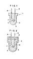
- FIG. 1 illustrates one preferred embodiment of the light-emitting or receiving device according to the present invention.
- the light-emitting or receiving device 1 may be any such device and is not particularly limited in shape or the like insofar as a light-emitting or receiving element 4, for example, a diode 4 (such as light-emitting diode or ultraviolet light-emitting diode) is encapsulated with a specific polymer 3.
- a diode 4 such as light-emitting diode or ultraviolet light-emitting diode
- lead frames 6 and 6 which project beyond the polymer 3 are provided on the upper surface of the polymer 3.
- One lead frame 6 is connected to a die bonding electrode 7 to which the light-emitting or receiving element 4 is secured.
- the other lead frame 6 is connected to a bonding wire 5 such as a gold wire.
- the bonding wire 5 is connected to the light-emitting or receiving element 4.
- a lower portion of the lead frames 6, die bonding electrode 7, and bonding wire 5 are sealed in the polymer 3.
- the light-emitting or receiving device of the present invention is characterized by encapsulation with a specific polymer, more particularly by encapsulation with a polymer of a polymerizable liquid composition (to be referred to as encapsulant A, hereinafter) comprising (a) a monomer or an oligomer or a mixture thereof containing a diallyl compound as an essential ingredient.
- encapsulant A a polymerizable liquid composition
- the encapsulant [A] prior to polymerization into the polymer with which the light-emitting or receiving device of the present invention is encapsulated is a polymerizable liquid composition comprising (a) a monomer or an oligomer or a mixture thereof containing a diallyl compound as an essential ingredient, preferably comprising (a) a monomer or an oligomer or a mixture thereof of a bis(allyl carbonate) of an aliphatic, cycloaliphatic or aromatic dihydric alcohol as an essential ingredient.
- diallyl compounds include a composition comprising (a') a monomer or an oligomer or a mixture thereof of a bis(allyl carbonate) of an aliphatic, cycloaliphatic or aromatic dihydric alcohol having the general formula: wherein R is a residue of a dihydric alcohol, and n has a value or an average value in the range of from 1 to 10, preferably from 2 to 10.
- Component (a') is preferably the reaction product of diallyl carbonate and a dihydric alcohol in a molar ratio of 4:1 or lower, more preferably in a molar ratio of 2:1.
- dihydric alcohol examples include ethylene glycol, 1,3-propanediol, 1,4-butanediol, 1,6-hexanediol, diethylene glycol, polyethylene glycol, dipropylene glycol, propylene glycol, neopentyl glycol, trimethylpentane diol, cyclohexane dimethanol, bis(hydroxymethyl)tricyclodecane, 2,7-norbornane diol, a,a'-xylene diol, 1,4-bis (hydroxyethoxybenzene), and 2,2-bis[4-(hydroxyethoxy)phenyi]propane alone and mixtures thereof.
- the encapsulant [A] of the present invention is preferably a liquid composition comprising components (a"), (b), and (c) shown below.
- Japanese Patent Application Kokai No. 59-140214 is incorporated herein by reference.
- the preferred composition comprises
- the preferred component (a") is the reaction product of diallyl carbonate and a dihydric alcohol in a molar ratio of 4:1 or lower, more preferably in a molar ratio of 2:1.
- the dihydric alcohol is preferably selected from the group consisting of ethylene glycol, 1,3-propanediol, 1,4-butanediol, 1,6-hexanediol, diethylene glycol, polyethylene glycol, dipropylene glycol, propylene glycol, neopentyl glycol, trimethylpentane diol, cyclohexane dimethanol, bis(hydroxymethyl)tricyclodecane, 2,7-norbornane diol, a,a'-xylene diol, 1,4-bis(hydroxyethoxybenzene), and 2,2-bis[4-(hydroxyethoxy)phenyl]propane.
- the preferred component (b) is the reaction product of diallyl carbonate and a di- or trihydric alcohol in a molar ratio of 6:1 or higher, more preferably in a molar ratio of 12:1.
- the di- or trihydric alcohol is preferably selected from the group consisting of ethylene glycol, 1,3-propanediol, 1,4-butanediol, 1,6-hexanediol, diethylene glycol, polyethylene glycol, dipropylene glycol, propylene glycol, neopentyl glycol, trimethylpentane diol, cyclohexane dimethanol, bis(hydroxymethyl)tricyclodecane, 2,7-norbornane diol, a,a'-xylene diol, 1,4-bis(hydroxyethoxybenzene), 2,2-bis[4-(hydroxyethoxy)phenyl]propane, trimethylol propane, and tri(hydroxyethyl) isocyan
- component (b) Also included in component (b) are diallyl phthalate, diallyl succinate, diallyl adipate, diallyl chlorendate, diallyl glycolate, diallyl naphthalene dicarboxylate, and triallyl mellitate.
- Component (c) is preferably selected from vinyl acetate, vinyl benzoate, methyl methacrylate, phenyl methacrylate, methyl acrylate, methyl maleate, maleic anhydride, and vinylidene chloride alone and mixtures thereof.
- diallyl compounds include
- the polymerizable liquid composition may contain another monomer and a filler in such amounts that they do not detract from the physical properties of the resulting polymer.
- a mono (meth)acrylic compound, di(meth)acrylic compound, or unsaturated carboxylic acid such as maleic anhydride may be added in an amount of up to 30 0 / 0 by weight
- a silane coupling agent such as vinyl triethoxysilane may be added in an amount of up to 10 0 / 0 by weight, based on the weight of the polymer.
- encapsulant [A] may further contain a polymerization initiator [B].
- the polymerization initiator [B] used in polymerizing encapsulant [A] may be any of photo polymerization initiators, thermal polymerization initiators, and photo and thermal polymerization initiators, and mixtures thereof.
- the photo polymerization initiators include electron beam and radiation polymerization initiators as well as photo polymerization initiators.
- a typical example of the photo polymerization initiator is 2-hydroxy-2-methyl-1-phenyl-propan-1-one.
- thermal polymerization initiators examples include peroxydicarbonates such as diisopropyl peroxydicarbonate, di-sec-butyl peroxydicarbonate, dicyclohexyl peroxydicarbonate, and tert-butyl perbenzoate; organic peroxides such as benzoyl peroxide, acetyl peroxide, tert-butyl hydroperoxide, cumene hydroperoxide, di-tert-butyl peroxide, tert-butyl peroxybenzoate, lauroyl peroxide, diisopropyl peroxydicarbonate, dimethyl ethyl ketone peroxide, and diacyl peroxide; and radical initiators such as azobisisobutyronitrile and azobismethylisovaleronitrile.
- peroxydicarbonates such as diisopropyl peroxydicarbonate, di-sec-butyl peroxydicarbonate, dicyclohexyl
- a typical example of the photo and thermal polymerization initiators is the compound of the following formula:
- Polymerization initiator [B] may be used to polymerize encapsulant [A] in an amount of 0.1 to 100/0 by weight, preferably 1 to 60/o by weight based on encapsulant [A].
- Encapsulant [A] may be used in semi-cured state or B stage if desired.
- the method for encapsulating the element 4 with encapsulant [A] is not particularly limited insofar as the method can form the polymer 3 (see FIG. 1) by placing the element 4 in a mold 2, filling the mold with encapsulant [A] 13, polymerizing encapsulant [A] as shown in FIG. 2.
- the following encapsulating method is preferred.
- Encapsulant [A] is polymerized in the mold while the surface of encapsulant [A] 13 in the mold is in contact with an inert gas atmosphere having an oxygen concentration of up to 1 0 / 0 , preferably up to 0.50/o, more preferably up to 0.01%.
- encapsulant [A] to be polymerized in the presence of a radical polymerization initiator is in contact with air, oxygen will consume active radicals so that the surface of the polymerizing encapsulant in contact with air may sometimes remain liquid or gel without reaching a sufficient molecular weight.
- the atmosphere under which polymerization is carried out should be an inert gas such as nitrogen and argon having an oxygen concentration of up to 1 0 / 0 , preferably up to 0.5 0 /o, more preferably up to 0.01%.
- Encapsulant [A] is polymerized in the mold while the surface of encapsulant [A] 13 in the mold is covered with a liquid [C] 8 having low solubility in encapsulant [A] 13 and a lower density than encapsulant [A] 13.
- Liquid [C] is not particularly limited as long as it is less soluble in encapsulant [A] and has a lower density than encapsulant [A].
- the density of liquid [C] is preferably from 0.7 to 1 g/cm 3 , more preferably from 0.8 to 0.95 g/cm 3 .
- Liquid [C] may be water, for example, which seals any opening to block oxygen. Water is suitable for polymerization at relatively low temperatures because of its high vapor pressure.
- Liquid [C] may also be a liquid synthetic hydrocarbon polymer having a low molecular weight or a liquid hydrocarbon mixture such as mineral oil.
- Examples of the synthetic hydrocarbon polymers include poly(a-olefin) oils such as polydecene-1, alkyl aromatic oils such as alkylbenzenes, polybutene oil or liquid polybutene, polyhexene, alkylnaphthene oils such as 2,4-dicyclohexyl-2-methylpentane oil, and ethylene-a-olefin random copolymer oils such as ethylene-propylene random copolymer oil.
- poly(a-olefin) oils such as polydecene-1
- alkyl aromatic oils such as alkylbenzenes
- polyhexene such as 2,4-dicyclohexyl-2-methylpentane oil
- ethylene-a-olefin random copolymer oils such as ethylene-propylene random copolymer oil.
- Preferred among them are those having a molecular weight of at least 500, more preferably from 1,000 to 10,000.
- ethylene-a-olefin random copolymer oils having a number average molecular weight (Mn) of from 500 to 5,000, especially from 1,500 to 3,000.
- liquid, low-molecular weight ethylene-a-olefin copolymers consisting of 30 to 70 mol O /o of ethylene units and 30 to 70 molO/o of a-olefin units and having a number average molecular weight (Mn) of from 1,000 to 5,000 and a Q value (weight average molecular weight/number average molecular weight) of up to 3.
- liquid [C] is a liquid polyolefin or the like
- the liquid itself exhibits mold release effect, considerably facilitating mold release operation.
- the liquid polyolefin may be readily removed with an organic solvent such as hexane, kerosene, and trichloroethylene.
- Encapsulant [A] is polymerized in the mold while the surface of encapsulant [A] in the mold is covered with liquid [C] and further with an inert gas atmosphere having an oxygen concentration of up to 1%. Better results are obtained from the combined use of encapsulating methods (1) and (2).
- Polymerization may be carried out under various conditions depending on the identity of polymerization initiator.
- the composition may be heated in a heating tank to a temperature of about 30 to 150° C, preferably about 40 to 120°C for about 1/2 to 72 hours, preferably about 1 to 4 hours, although the exact value will vary with the shape and size.
- polymerization may be carried out under a high-pressure mercury lamp with a power of 60 to 150 W/cm for about 1 minute to 2 hours, preferably 3 to 30 minutes at a temperature of about 40 to 120° C, preferably about 60 to 100°C.
- An assembly of a GaAlAs light-emitting diode with lead frames was set in a mold of polypropylene having an inner diameter of 5 mm and a depth of 10 mm.
- the mold was changed. with a homogeneously mixed liquid composition given below as encapsulant [A]-I.
- the mold was placed in a vacuum oven, which was purged with argon gas and then heated stepwise from 40°C to 90°C, completing polymerization in 3 hours.
- An assembly of a light-emitting diode with lead frames was set in a mold TPX O having an inner diameter of 5 mm and a depth of 10 mm as shown in FIG. 2.
- a composition given below as encapsulant [A]-II was cast into the mold and then covered with a layer of a liquid ethylene-propylene copolymer (Mn 2500, Q 2.0, specific gravity 0.846) having a thickness of about 2 mm.
- the mold was placed in an air oven, which was heated stepwise from 40°C from 90°C, completing polymerization in 3 hours.
- Example 2 The procedure of Example 2. was repeated except that encapsulant [A]-II was replaced by [A]-I, completing polymerization in 3 hours as in Example 2.
- An assembly of a light-emitting diode with lead frames was set in a mold of TPX® having an inner diameter of 5 mm and a depth of 10 mm as shown in FIG. 2.
- An epoxy resin of the light-emitting diode encapsulating grade was cast into the mold, the epoxy resin consisting of 100 parts of a major agent, Pelnox XN-1886-3 and 110 parts of a curing agent, Pelcure XV-2263 (manufactured by NIPPON PELNOX K.K.). The epoxy resin was cured at 120° C for 8 hours.
- Mold release was evaluated by removing the cured resin from the mold without using a mold release agent.
- encapsulants [A]-I and [A]-II were polymerized into plates of 3.0 mm thick by the same method as described for Examples 1-3 and Comparative Example 1 and measured for light transmittance using a spectrophotometer.
- Light transmittance measurement auto-recording spectrophotometer, model U-3400 of Hitachi, Ltd.
- the light transmittance and luminous power were measured before and after the above-mentioned weathering tests.
- a barrel portion of the encapsulant was measured for surface hardness by a similar method according to JIS K5401.
- the light-emitting or receiving device of the present invention which is encapsulated with a specific polymer has improved weatherability, chemical resistance, hardness, and optical properties such as transparency.
- the encapsulant of the present invention is used in light-emitting or receiving devices having the above-mentioned characteristics and has a reduced curing time and improved mold release after curing.
- the applications in which the light-emitting or receiving device of the present invention is utilized include light emitting devices such as LED, laser diodes, photosensors, photodiodes, and electroluminescence cells as well as light-receiving devices such as photodiodes.
- the encapsulating method of the present invention using a cover liquid can produce a light-emitting or receiving device with a high surface hardness.
- the device can be readily removed from the mold because the cover liquid has mold release property.
- the encapsulating method of the present invention using an inert gas atmosphere having an oxygen concentration of up to 1% can produce a light-emitting or receiving device with a high surface hardness at a low cost because the product and the mold need not be cleaned after molding.
Abstract
Description
- This invention relates to light-emitting or receiving devices (or parts) such as LED, laser diodes, and photosensors, and more particularly, to encapsulants having improved weatherability, chemical resistance, hardness, and optical properties and light-emitting or receiving devices using the same and having such improved properties.
- This invention further relates to an encapsulating method useful in the manufacture of light-emitting or receiving devices.
- In the prior art manufacture of light-emitting or receiving devices such as LED, laser diodes, and photosensors, light-emitting diodes and similar elements are encapsulated by casting epoxy resin followed by polymerization.
- The encapsulating method using epoxy resin, however, has the following drawbacks.
- (1) Since the epoxy resin has poor weatherability, its outdoor use is substantially limited. This is because light-emitting elements experience a drastic drop in luminous power with a lapse of time and light-receiving elements experience a drop in light-receiving sensitivity with a lapse of time when used outdoors.
- (2) Since it takes a long time of 5 to 20 hours to cure the epoxy resin, the productivity of light-emitting or receiving devices is low.
- (3) Since the epoxy resin has poor mold release characteristics, the productivity of light-emitting or receiving devices is low.
- If a mold release agent is used to improve mold release, it is necessary to remove the mold release agent adhered to the surface of the epoxy resin encapsulant, creating a serious problem in the production process.
- An object of the present invention is to overcome the above-mentioned problems of the prior art and to provide a light-emitting or receiving device having improved weatherability, chemical resistance, hardness, and optical properties.
- Another object of the present invention is to provide an encapsulant for light-emitting or receiving elements which is used to form light-emitting or receiving devices having the above-mentioned properties and characterized by a reduced curing time and good mold release.
- Another object of the present invention is to provide an encapsulating method suitable for the manufacture of a light-emitting or receiving device (or part) having improved weatherability, chemical resistance, hardness, and optical properties.
- According to a first aspect of the present invention, there is provided a light-emitting or receiving device wherein a light-emitting or receiving element is encapsulated with a polymer of a polymerizable liquid composition comprising (a) a monomer or an oligomer or a mixture thereof containing a diallyl compound as an essential ingredient.
- According to a second aspect of the present invention, there is provided an encapsulant for light-emitting or receiving elements, comprising (a) a monomer or an oligomer or a mixture thereof containing a diallyl compound as an essential ingredient.
- According to a first aspect of the present invention, there is provided a method for encapsulating a light-emitting or receiving element, comprising placing a light-emitting or receiving element in a mold, casting an encapsulant [A] comprising (a) a monomer or an oligomer or a mixture thereof containing a diallyl compound as an essential ingredient into the mold, and polymerizing encapsulant [A].
- According to a second aspect of the present invention, there is provided a method for encapsulating a light-emitting or receiving element, comprising placing a light-emitting or receiving element in a mold, casting an encapsulant [A] comprising (a) a monomer or an oligomer or a mixture thereof containing a diallyl compound as an essential ingredient into the mold, and polymerizing encapsulant [A] while a liquid [C] having less solubility in encapsulant [A] and a lower density than encapsulant [A] is present on encapsulant [A].
- According to a third aspect of the present invention, there is provided a method for encapsulating a light-emitting or receiving element, comprising placing a light-emitting or receiving element in a mold, casting an encapsulant [A] comprising (a) a monomer or an oligomer or a mixture thereof containing a diallyl compound as an essential ingredient into the mold, and polymerizing encapsulant [A] while keeping the surface of encapsulant [A] in contact with an inert gas atmosphere having an oxygen concentration of up to 10/0.
- The polymerizable liquid composition comprising (a) a monomer or an oligomer or a mixture thereof of a bis(allyl carbonate) of an aliphatic, cycloaliphatic or aromatic dihydric alcohol as an essential ingredient is preferred.
- The liquid [C] is preferred a liquid synthetic hydrocarbon polymer having a low molecular weight or a liquid hydrocarbon mixture or a mixture thereof.
- The monomer or oligomer or mixture thereof containing a diallyl compound as an essential ingredient used in the present disclosure encompasses a monomer alone, an oligomer alone, a mixture of a monomer and an oligomer, a mixture of two or more monomers, a mixture of two or more oligomers, and a mixture of at least one monomer and at least one oligomer.
- The polymer used in the present disclosure may be either a homopolymer or a copolymer.
-
- FIG. 1 is a vertical cross section of a light-emitting or receiving device according to the present invention.
- FIG. 2 is a vertical cross section illustrating an encapsulating method.
- The invention will be described in detail by referring to the preferred embodiments shown in the drawings.
- FIG. 1 illustrates one preferred embodiment of the light-emitting or receiving device according to the present invention.
- The light-emitting or receiving device 1 according to the present invention may be any such device and is not particularly limited in shape or the like insofar as a light-emitting or receiving
element 4, for example, a diode 4 (such as light-emitting diode or ultraviolet light-emitting diode) is encapsulated with aspecific polymer 3. - In general,
lead frames polymer 3 are provided on the upper surface of thepolymer 3. Onelead frame 6 is connected to adie bonding electrode 7 to which the light-emitting or receivingelement 4 is secured. Theother lead frame 6 is connected to abonding wire 5 such as a gold wire. The bondingwire 5 is connected to the light-emitting or receivingelement 4. - A lower portion of the
lead frames 6, diebonding electrode 7, and bondingwire 5 are sealed in thepolymer 3. - The light-emitting or receiving device of the present invention is characterized by encapsulation with a specific polymer, more particularly by encapsulation with a polymer of a polymerizable liquid composition (to be referred to as encapsulant A, hereinafter) comprising (a) a monomer or an oligomer or a mixture thereof containing a diallyl compound as an essential ingredient.
- The encapsulant [A] prior to polymerization into the polymer with which the light-emitting or receiving device of the present invention is encapsulated is a polymerizable liquid composition comprising (a) a monomer or an oligomer or a mixture thereof containing a diallyl compound as an essential ingredient, preferably comprising (a) a monomer or an oligomer or a mixture thereof of a bis(allyl carbonate) of an aliphatic, cycloaliphatic or aromatic dihydric alcohol as an essential ingredient.
- Examples of the diallyl compounds include a composition comprising (a') a monomer or an oligomer or a mixture thereof of a bis(allyl carbonate) of an aliphatic, cycloaliphatic or aromatic dihydric alcohol having the general formula:

- Component (a') is preferably the reaction product of diallyl carbonate and a dihydric alcohol in a molar ratio of 4:1 or lower, more preferably in a molar ratio of 2:1.
- Preferred examples of the dihydric alcohol include ethylene glycol, 1,3-propanediol, 1,4-butanediol, 1,6-hexanediol, diethylene glycol, polyethylene glycol, dipropylene glycol, propylene glycol, neopentyl glycol, trimethylpentane diol, cyclohexane dimethanol, bis(hydroxymethyl)tricyclodecane, 2,7-norbornane diol, a,a'-xylene diol, 1,4-bis (hydroxyethoxybenzene), and 2,2-bis[4-(hydroxyethoxy)phenyi]propane alone and mixtures thereof.
- The encapsulant [A] of the present invention is preferably a liquid composition comprising components (a"), (b), and (c) shown below. Japanese Patent Application Kokai No. 59-140214 is incorporated herein by reference.
- The preferred composition comprises
- (a") 10 to 900/0 by weight of an oligomer or a mixture of oligomers of a bis(allyl carbonate) of an aliphatic, cycloaliphatic or aromatic dihydric alcohol having the general formula:

- (b) 0 to 900/0 by weight of a compound selected from the group consisting of (b-1) a monomeric di- or tri(allyl carbonate) of an aliphatic, cycloaliphatic or aromatic di- or trihydric alcohol having the general formula:


- (c) 0 to 300/0 by weight of an acrylic or vinyl monomer; with the proviso that the total of components (b) and (c) is more than 0.
- The preferred component (a") is the reaction product of diallyl carbonate and a dihydric alcohol in a molar ratio of 4:1 or lower, more preferably in a molar ratio of 2:1. The dihydric alcohol is preferably selected from the group consisting of ethylene glycol, 1,3-propanediol, 1,4-butanediol, 1,6-hexanediol, diethylene glycol, polyethylene glycol, dipropylene glycol, propylene glycol, neopentyl glycol, trimethylpentane diol, cyclohexane dimethanol, bis(hydroxymethyl)tricyclodecane, 2,7-norbornane diol, a,a'-xylene diol, 1,4-bis(hydroxyethoxybenzene), and 2,2-bis[4-(hydroxyethoxy)phenyl]propane.
- The preferred component (b) is the reaction product of diallyl carbonate and a di- or trihydric alcohol in a molar ratio of 6:1 or higher, more preferably in a molar ratio of 12:1. The di- or trihydric alcohol is preferably selected from the group consisting of ethylene glycol, 1,3-propanediol, 1,4-butanediol, 1,6-hexanediol, diethylene glycol, polyethylene glycol, dipropylene glycol, propylene glycol, neopentyl glycol, trimethylpentane diol, cyclohexane dimethanol, bis(hydroxymethyl)tricyclodecane, 2,7-norbornane diol, a,a'-xylene diol, 1,4-bis(hydroxyethoxybenzene), 2,2-bis[4-(hydroxyethoxy)phenyl]propane, trimethylol propane, and tri(hydroxyethyl) isocyanurate alone and mixtures thereof.
- Also included in component (b) are diallyl phthalate, diallyl succinate, diallyl adipate, diallyl chlorendate, diallyl glycolate, diallyl naphthalene dicarboxylate, and triallyl mellitate.
- Component (c) is preferably selected from vinyl acetate, vinyl benzoate, methyl methacrylate, phenyl methacrylate, methyl acrylate, methyl maleate, maleic anhydride, and vinylidene chloride alone and mixtures thereof.
- Another example of the diallyl compounds include
- (I) a copolymerizable composition comprising a diallyl ester of a nuclearly halo-substituted benzene dicarboxylic acid and diethylene glycol diallyl carbonate as disclosed in Japanese Patent Application Kokai No. 59-45312;
- (II) a copolymerizable composition comprising at least one ester of a nuclearly halo-substituted benzene dicarboxylic acid (for example, bisallyl 2,4-dichloroterephthalate) and at least one radical-polymerizable monofunctional monomer bearing an aromatic ring and capable of forming a homopolymer having a refractive index of at least 1.55 (for example, phenyl methacrylate) as disclosed in Japanese Patent Application Kokai No. 59-8709;
- (III) a copolymerizable composition comprising at least one bisallyl carbonate or bis-β-methylallyl carbonate (for example, 1,4-bis(hydroxyethoxy)benzene bisallyl carbonate) and at least one radical-polymerizable monofunctional monomer bearing an aromatic ring and capable of forming a homopolymer having a refractive index of at least 1.55 (for example, phenyl methacrylate) as disclosed in Japanese Patent Application Kokai No. 59-8710;
- (IV) a copolymerizable composition comprising a monomer obtained by reacting a monool (for example, 4-benzyl-phenol) with an unsaturated carboxylic acid or chloride thereof (for example, acrylic acid or chloride thereof) and a radical-polymerizable monomer capable of forming a homopolymer having a refractive index of at least 1.55 (for example, styrene) as disclosed in Japanese Patent Application Kokai No. 59-96109;
- (V) a copolymerizable composition comprising a chlorobenzoic acid allyl ester (for example, 2,3-dichlorobenzoic acid diallyl ester) and a difunctional monomer (for example, tetrabromophthalic acid diallyl ester) as disclosed in Japanese Patent Application Kokai No. 59-96113;
- (VI) a copolymerizable composition as disclosed in Japanese Patent Application Kokai No. 59-184210;
- (VII) diethylene glycol bisallyl carbonate; and
- (VIII) copolymereizable compositions of a bisallyl compound such as diethylene glycol bisallyl carbonate, 1-4-bis(hydroxyethoxy)benzene bisallyl carbonate, and 2,4-dichloroterephthalic acid bisallyl ester and a vinyl monomer having an aromatic ring such as phenyl methacrylate and benzyl methacrylate.
- The polymerizable liquid composition may contain another monomer and a filler in such amounts that they do not detract from the physical properties of the resulting polymer. For example, a mono (meth)acrylic compound, di(meth)acrylic compound, or unsaturated carboxylic acid such as maleic anhydride may be added in an amount of up to 300/0 by weight, or a silane coupling agent such as vinyl triethoxysilane may be added in an amount of up to 100/0 by weight, based on the weight of the polymer.
- In the practice of the present invention, encapsulant [A] may further contain a polymerization initiator [B].
- The polymerization initiator [B] used in polymerizing encapsulant [A] may be any of photo polymerization initiators, thermal polymerization initiators, and photo and thermal polymerization initiators, and mixtures thereof.
- The photo polymerization initiators include electron beam and radiation polymerization initiators as well as photo polymerization initiators.
- A typical example of the photo polymerization initiator is 2-hydroxy-2-methyl-1-phenyl-propan-1-one.
- Examples of the thermal polymerization initiators include peroxydicarbonates such as diisopropyl peroxydicarbonate, di-sec-butyl peroxydicarbonate, dicyclohexyl peroxydicarbonate, and tert-butyl perbenzoate; organic peroxides such as benzoyl peroxide, acetyl peroxide, tert-butyl hydroperoxide, cumene hydroperoxide, di-tert-butyl peroxide, tert-butyl peroxybenzoate, lauroyl peroxide, diisopropyl peroxydicarbonate, dimethyl ethyl ketone peroxide, and diacyl peroxide; and radical initiators such as azobisisobutyronitrile and azobismethylisovaleronitrile.
- A typical example of the photo and thermal polymerization initiators is the compound of the following formula:

- Polymerization initiator [B] may be used to polymerize encapsulant [A] in an amount of 0.1 to 100/0 by weight, preferably 1 to 60/o by weight based on encapsulant [A].
- Encapsulant [A] may be used in semi-cured state or B stage if desired.
- The method for encapsulating the
element 4 with encapsulant [A] is not particularly limited insofar as the method can form the polymer 3 (see FIG. 1) by placing theelement 4 in a mold 2, filling the mold with encapsulant [A] 13, polymerizing encapsulant [A] as shown in FIG. 2. The following encapsulating method is preferred. - (1) Encapsulant [A] is polymerized in the mold while the surface of encapsulant [A] 13 in the mold is in contact with an inert gas atmosphere having an oxygen concentration of up to 10/0, preferably up to 0.50/o, more preferably up to 0.01%.
- If encapsulant [A] to be polymerized in the presence of a radical polymerization initiator is in contact with air, oxygen will consume active radicals so that the surface of the polymerizing encapsulant in contact with air may sometimes remain liquid or gel without reaching a sufficient molecular weight.
- In order to complete polymerization evenly so that the surface hardness may reach a pencil hardness of at least 2B, preferably at least HB, the atmosphere under which polymerization is carried out should be an inert gas such as nitrogen and argon having an oxygen concentration of up to 10/0, preferably up to 0.50/o, more preferably up to 0.01%.
- (2) Encapsulant [A] is polymerized in the mold while the surface of encapsulant [A] 13 in the mold is covered with a liquid [C] 8 having low solubility in encapsulant [A] 13 and a lower density than encapsulant [A] 13. Liquid [C] is not particularly limited as long as it is less soluble in encapsulant [A] and has a lower density than encapsulant [A].
- The density of liquid [C] is preferably from 0.7 to 1 g/cm3, more preferably from 0.8 to 0.95 g/cm3.
- Consumption of radicals in encapsulant [A] can be controlled for the same reason as in method (1).
- Liquid [C] may be water, for example, which seals any opening to block oxygen. Water is suitable for polymerization at relatively low temperatures because of its high vapor pressure.
- Liquid [C] may also be a liquid synthetic hydrocarbon polymer having a low molecular weight or a liquid hydrocarbon mixture such as mineral oil.
- Examples of the synthetic hydrocarbon polymers include poly(a-olefin) oils such as polydecene-1, alkyl aromatic oils such as alkylbenzenes, polybutene oil or liquid polybutene, polyhexene, alkylnaphthene oils such as 2,4-dicyclohexyl-2-methylpentane oil, and ethylene-a-olefin random copolymer oils such as ethylene-propylene random copolymer oil.
- Preferred among them are those having a molecular weight of at least 500, more preferably from 1,000 to 10,000.
- Also preferred are ethylene-a-olefin random copolymer oils having a number average molecular weight (Mn) of from 500 to 5,000, especially from 1,500 to 3,000.
- Particularly preferred are liquid, low-molecular weight ethylene-a-olefin copolymers consisting of 30 to 70 molO/o of ethylene units and 30 to 70 molO/o of a-olefin units and having a number average molecular weight (Mn) of from 1,000 to 5,000 and a Q value (weight average molecular weight/number average molecular weight) of up to 3.
- When liquid [C] is a liquid polyolefin or the like, the liquid itself exhibits mold release effect, considerably facilitating mold release operation. At the end of polymerization, the liquid polyolefin may be readily removed with an organic solvent such as hexane, kerosene, and trichloroethylene.
- (3) Encapsulating methods (1) and (2) may be combined.
- Encapsulant [A] is polymerized in the mold while the surface of encapsulant [A] in the mold is covered with liquid [C] and further with an inert gas atmosphere having an oxygen concentration of up to 1%. Better results are obtained from the combined use of encapsulating methods (1) and (2).
- Polymerization may be carried out under various conditions depending on the identity of polymerization initiator. In the case of thermal polymerization, the composition may be heated in a heating tank to a temperature of about 30 to 150° C, preferably about 40 to 120°C for about 1/2 to 72 hours, preferably about 1 to 4 hours, although the exact value will vary with the shape and size. In the case of photo polymerization, polymerization may be carried out under a high-pressure mercury lamp with a power of 60 to 150 W/cm for about 1 minute to 2 hours, preferably 3 to 30 minutes at a temperature of about 40 to 120° C, preferably about 60 to 100°C.
- Examples of the present invention are given below by way of illustration.
- An assembly of a GaAlAs light-emitting diode with lead frames was set in a mold of polypropylene having an inner diameter of 5 mm and a depth of 10 mm. The mold was changed. with a homogeneously mixed liquid composition given below as encapsulant [A]-I. The mold was placed in a vacuum oven, which was purged with argon gas and then heated stepwise from 40°C to 90°C, completing polymerization in 3 hours.
-
- The reaction product obtained by reacting diallyl carbonate with diethylene glycol in a molar ratio of 2:1 in the presence of sodium ethoxide under the conditions described in Japanese Patent Application Kokai No. 56-133246 (consisting of 300/0 by weight of diethylene glycol bisallyl carbonate and 70% by weight of oligo-carbonate, n = 3 to 10) 55% by weight
- Tris(allyl carbonate) of tris(hydroxyethyl) isocyanurate obtained by reacting diallyl carbonate with tris(hydroxyethyl) isocyanurate in a molar ratio of 12:1 12.40/0 by weight
- Diethylene glycol bisallyl carbonate 27.5% by weight
-
Vinyl acetate 50/0 by weight - Polymerization initiator (per 100 parts of the foregoing ingredients)
- Diisopropyl peroxydicarbonate 2.5 pbw
- An assembly of a light-emitting diode with lead frames was set in a mold TPXO having an inner diameter of 5 mm and a depth of 10 mm as shown in FIG. 2. A composition given below as encapsulant [A]-II was cast into the mold and then covered with a layer of a liquid ethylene-propylene copolymer (Mn 2500, Q 2.0, specific gravity 0.846) having a thickness of about 2 mm. The mold was placed in an air oven, which was heated stepwise from 40°C from 90°C, completing polymerization in 3 hours.
-
- The reaction product obtained by reacting diallyl carbonate with diethylene glycol in a molar ratio of 2:1 in the presence of sodium ethoxide under the conditions described in Japanese Patent Application Kokai No. 56-133246 (consisting of 300/o by weight of diethylene glycol bisallyl carbonate and 70% by weight of oligo-carbonate, n = 3 to 10) 58% by weight
- Tris(allyl carbonate) of tris(hydroxyethyl) isocyanurate obtained by reacting diallyl carbonate with tris(hydroxyethyl) isocyanurate in a molar ratio of 12:1 13% by weight
- Diethylene glycol disallyl carbonate 29% by weight
- Polymerization initiator (per 100 parts of the foregoing ingredients)
- Diisopropyl peroxydicarbonate 2.7 pbw
- The procedure of Example 2. was repeated except that encapsulant [A]-II was replaced by [A]-I, completing polymerization in 3 hours as in Example 2.
- An assembly of a light-emitting diode with lead frames was set in a mold of TPX® having an inner diameter of 5 mm and a depth of 10 mm as shown in FIG. 2. An epoxy resin of the light-emitting diode encapsulating grade was cast into the mold, the epoxy resin consisting of 100 parts of a major agent, Pelnox XN-1886-3 and 110 parts of a curing agent, Pelcure XV-2263 (manufactured by NIPPON PELNOX K.K.). The epoxy resin was cured at 120° C for 8 hours.
- The light-emitting or receiving devices obtained in the foregoing Examples and Comparative Example were evaluated as follows, with the results shown in Table 1.
- Mold release was evaluated by removing the cured resin from the mold without using a mold release agent.
- ⓞ: very easily releasable
- O: manually releasable
- X: manually unreleasable
- Visual observation
- ○: good
- @: excellent
- In the case of Comparative Example only, evaluation was made by removing the cured resin using a silicone mold release agent for light-emitting diodes. No mold release agent was used in Examples.
- Separately, encapsulants [A]-I and [A]-II were polymerized into plates of 3.0 mm thick by the same method as described for Examples 1-3 and Comparative Example 1 and measured for light transmittance using a spectrophotometer.
- Light transmittance measurement: auto-recording spectrophotometer, model U-3400 of Hitachi, Ltd.
- Using an accelerated weathering tester (model SUV-W11 of Iwasaki Electric K.K.), a sample was exposed to light under the following conditions.
- Ultraviolet intensity: 100 mW/cm2
- Black panel temperature: 63° C
- Relative humidity: 50-70%
- A cycle consisting of an exposure time of 8 hours and a dewing time of 4 hours was repeated to a total exposure of 48 hours.
- Accelerated weathering tester (model WEL-6X-HC-BEC of Suga Tester K.K.).
- Light source: 6.0 kW xenon lamp
- Black panel temperature: 63°C
- Relative humidity: 50%
- A cycle consisting of an exposure time of 200 minutes (including a raining time of 18 minutes) was repeated to a total exposure of 100 hours.
- The light transmittance and luminous power were measured before and after the above-mentioned weathering tests.
- A barrel portion of the encapsulant was measured for surface hardness by a similar method according to JIS K5401.

- The light-emitting or receiving device of the present invention which is encapsulated with a specific polymer has improved weatherability, chemical resistance, hardness, and optical properties such as transparency. The encapsulant of the present invention is used in light-emitting or receiving devices having the above-mentioned characteristics and has a reduced curing time and improved mold release after curing. The applications in which the light-emitting or receiving device of the present invention is utilized include light emitting devices such as LED, laser diodes, photosensors, photodiodes, and electroluminescence cells as well as light-receiving devices such as photodiodes.
- The encapsulating method of the present invention using a cover liquid can produce a light-emitting or receiving device with a high surface hardness. The device can be readily removed from the mold because the cover liquid has mold release property.
- The encapsulating method of the present invention using an inert gas atmosphere having an oxygen concentration of up to 1% can produce a light-emitting or receiving device with a high surface hardness at a low cost because the product and the mold need not be cleaned after molding.
Claims (7)
Applications Claiming Priority (4)
| Application Number | Priority Date | Filing Date | Title |
|---|---|---|---|
| JP78910/88 | 1988-03-31 | ||
| JP78909/88 | 1988-03-31 | ||
| JP63078909A JPH01251745A (en) | 1988-03-31 | 1988-03-31 | Light-emitting or light-receiving device; sealing agent for light-emitting element or photodetector |
| JP63078910A JPH01251726A (en) | 1988-03-31 | 1988-03-31 | Method of sealing light-emitting element or photodetector |
Publications (3)
| Publication Number | Publication Date |
|---|---|
| EP0335688A2 true EP0335688A2 (en) | 1989-10-04 |
| EP0335688A3 EP0335688A3 (en) | 1990-07-18 |
| EP0335688B1 EP0335688B1 (en) | 1994-06-01 |
Family
ID=26419967
Family Applications (1)
| Application Number | Title | Priority Date | Filing Date |
|---|---|---|---|
| EP89303104A Expired - Lifetime EP0335688B1 (en) | 1988-03-31 | 1989-03-29 | Light-emitting or receiving device, encapsulant for light-emitting or receiving element and the method for encapsulating thereof |
Country Status (7)
| Country | Link |
|---|---|
| US (1) | US5101264A (en) |
| EP (1) | EP0335688B1 (en) |
| KR (1) | KR920005318B1 (en) |
| CN (1) | CN1015583B (en) |
| AT (1) | ATE106610T1 (en) |
| AU (1) | AU608703B2 (en) |
| DE (1) | DE68915600T2 (en) |
Cited By (5)
| Publication number | Priority date | Publication date | Assignee | Title |
|---|---|---|---|---|
| EP0420629A1 (en) * | 1989-09-29 | 1991-04-03 | Mitsui Petrochemical Industries, Ltd. | Light-emitting or receiving device and method for preparing the same |
| ES2042351A2 (en) * | 1991-04-05 | 1993-12-01 | Olmos Diaz Francisco | System for inputting orders by pulses in sealed equipment |
| ES2078165A2 (en) * | 1993-12-16 | 1995-12-01 | Diaz Francisco Olmos | System for entering commands by key-pressure on sealed equipment. |
| EP0769506A1 (en) * | 1995-10-03 | 1997-04-23 | Kureha Kagaku Kogyo Kabushiki Kaisha | Plastic lid material for use in semiconductor device packages and production process thereof |
| US6903171B2 (en) | 1998-10-05 | 2005-06-07 | Promerus, Llc | Polymerized cycloolefins using transition metal catalyst and end products thereof |
Families Citing this family (8)
| Publication number | Priority date | Publication date | Assignee | Title |
|---|---|---|---|---|
| AU617447B2 (en) * | 1988-03-31 | 1991-11-28 | Mitsui Chemicals, Inc. | Process for preparing resins |
| US5514627A (en) * | 1994-01-24 | 1996-05-07 | Hewlett-Packard Company | Method and apparatus for improving the performance of light emitting diodes |
| US6507049B1 (en) * | 2000-09-01 | 2003-01-14 | General Electric Company | Encapsulants for solid state devices |
| JP5032017B2 (en) * | 2005-10-28 | 2012-09-26 | 株式会社東芝 | Semiconductor light emitting device, method for manufacturing the same, and semiconductor light emitting device |
| EP2530524B1 (en) | 2010-01-26 | 2019-05-29 | Nissan Chemical Corporation | Positive-type resist composition and method for producing microlens |
| DE102012108413A1 (en) * | 2012-09-10 | 2014-03-13 | Osram Opto Semiconductors Gmbh | Housing for an optoelectronic component, optoelectronic component and method for producing the optoelectronic component |
| CN106182584A (en) * | 2016-08-18 | 2016-12-07 | 中国人民解放军海军医学研究所 | For encapsulating the injection moulding process of underwater installation |
| ES2960434A1 (en) * | 2022-08-03 | 2024-03-04 | Quality Photonic Optics S L | METHOD FOR THE MANUFACTURE OF OPTICS EMBEDDED IN PHOTONIC COMPONENTS (Machine-translation by Google Translate, not legally binding) |
Citations (6)
| Publication number | Priority date | Publication date | Assignee | Title |
|---|---|---|---|---|
| JPS58186976A (en) * | 1982-04-26 | 1983-11-01 | Tokuyama Soda Co Ltd | Light emitting diode |
| JPS598710A (en) * | 1982-07-08 | 1984-01-18 | Mitsui Toatsu Chem Inc | Resin for high refractive index lens having excellent light resistance |
| EP0110447A1 (en) * | 1982-10-29 | 1984-06-13 | Rtc-Compelec | Method of encapsulating electronic components with plastic material by extrusion, and application to the production of electroluminescent diodes and to the encapsulation of electronic circuits |
| EP0114080A1 (en) * | 1983-01-13 | 1984-07-25 | ENICHEM SYNTHESIS S.p.A. | Polymerizable liquid composition adapted to produce polymers having outstanding optical and mechanical properties, polymers and articles obtained with said composition |
| JPS60103650A (en) * | 1983-11-11 | 1985-06-07 | Toshiba Chem Corp | Light emitting diode |
| US4623705A (en) * | 1980-03-05 | 1986-11-18 | Anic S.P.A. | Process for synthesizing allyl carbonates by polyhydric alcohols and their derivatives |
-
1989
- 1989-03-28 US US07/329,566 patent/US5101264A/en not_active Expired - Fee Related
- 1989-03-29 AT AT89303104T patent/ATE106610T1/en not_active IP Right Cessation
- 1989-03-29 AU AU32223/89A patent/AU608703B2/en not_active Ceased
- 1989-03-29 EP EP89303104A patent/EP0335688B1/en not_active Expired - Lifetime
- 1989-03-29 DE DE68915600T patent/DE68915600T2/en not_active Expired - Fee Related
- 1989-03-31 KR KR1019890004220A patent/KR920005318B1/en not_active IP Right Cessation
- 1989-03-31 CN CN89103278A patent/CN1015583B/en not_active Expired
Patent Citations (6)
| Publication number | Priority date | Publication date | Assignee | Title |
|---|---|---|---|---|
| US4623705A (en) * | 1980-03-05 | 1986-11-18 | Anic S.P.A. | Process for synthesizing allyl carbonates by polyhydric alcohols and their derivatives |
| JPS58186976A (en) * | 1982-04-26 | 1983-11-01 | Tokuyama Soda Co Ltd | Light emitting diode |
| JPS598710A (en) * | 1982-07-08 | 1984-01-18 | Mitsui Toatsu Chem Inc | Resin for high refractive index lens having excellent light resistance |
| EP0110447A1 (en) * | 1982-10-29 | 1984-06-13 | Rtc-Compelec | Method of encapsulating electronic components with plastic material by extrusion, and application to the production of electroluminescent diodes and to the encapsulation of electronic circuits |
| EP0114080A1 (en) * | 1983-01-13 | 1984-07-25 | ENICHEM SYNTHESIS S.p.A. | Polymerizable liquid composition adapted to produce polymers having outstanding optical and mechanical properties, polymers and articles obtained with said composition |
| JPS60103650A (en) * | 1983-11-11 | 1985-06-07 | Toshiba Chem Corp | Light emitting diode |
Non-Patent Citations (3)
| Title |
|---|
| PATENT ABSTRACTS OF JAPAN, vol. 8, no. 25 (E-225)[1462], 2nd February 1984; & JP-A-58 186 976 (TOKUYAMA SODA K.K.) 01-11-1983 * |
| PATENT ABSTRACTS OF JAPAN, vol. 8, no. 93 (C-220)[1530], 27th April 1984, page 11 C 220; & JP-A-59 008 710 (MITSUI TOATSU KAGAKU K.K.) 18-01-1984 * |
| PATENT ABSTRACTS OF JAPAN, vol. 9, no. 255 (E-349)[1978], 12th October 1985; & JP-A-60 103 650 (TOSHIBA CHEMICAL K.K.) 07-06-1985 * |
Cited By (6)
| Publication number | Priority date | Publication date | Assignee | Title |
|---|---|---|---|---|
| EP0420629A1 (en) * | 1989-09-29 | 1991-04-03 | Mitsui Petrochemical Industries, Ltd. | Light-emitting or receiving device and method for preparing the same |
| US5126826A (en) * | 1989-09-29 | 1992-06-30 | Mitsui Petrochemical Industries, Ltd. | Light-emitting or receiving device and method for preparing the same |
| ES2042351A2 (en) * | 1991-04-05 | 1993-12-01 | Olmos Diaz Francisco | System for inputting orders by pulses in sealed equipment |
| ES2078165A2 (en) * | 1993-12-16 | 1995-12-01 | Diaz Francisco Olmos | System for entering commands by key-pressure on sealed equipment. |
| EP0769506A1 (en) * | 1995-10-03 | 1997-04-23 | Kureha Kagaku Kogyo Kabushiki Kaisha | Plastic lid material for use in semiconductor device packages and production process thereof |
| US6903171B2 (en) | 1998-10-05 | 2005-06-07 | Promerus, Llc | Polymerized cycloolefins using transition metal catalyst and end products thereof |
Also Published As
| Publication number | Publication date |
|---|---|
| KR890015397A (en) | 1989-10-30 |
| DE68915600D1 (en) | 1994-07-07 |
| EP0335688B1 (en) | 1994-06-01 |
| CN1015583B (en) | 1992-02-19 |
| EP0335688A3 (en) | 1990-07-18 |
| KR920005318B1 (en) | 1992-07-02 |
| AU3222389A (en) | 1989-10-05 |
| US5101264A (en) | 1992-03-31 |
| DE68915600T2 (en) | 1994-09-15 |
| AU608703B2 (en) | 1991-04-11 |
| CN1038547A (en) | 1990-01-03 |
| ATE106610T1 (en) | 1994-06-15 |
Similar Documents
| Publication | Publication Date | Title |
|---|---|---|
| EP0420629B1 (en) | Light-emitting or receiving device and method for preparing the same | |
| US5101264A (en) | Light-emitting or receiving device with smooth and hard encapsulant resin | |
| KR101365834B1 (en) | Optical semiconductor encapsulating material | |
| KR101351212B1 (en) | Curable composition and fluorine-containing cured product | |
| JP5798033B2 (en) | Acrylate composition | |
| US8648160B2 (en) | Optical semiconductor sealing material | |
| JP2006241462A (en) | Composition for optical material, optical material, manufacturing method thereof, and liquid crystal display device using the same | |
| JP2007327031A (en) | Resin composition and optical member using cured product | |
| JP2006183061A (en) | Composition for electronic material, and electronic material | |
| AU619815B2 (en) | Electronic parts, encapsulant for electronic parts, and encapsulating method | |
| JPH01251745A (en) | Light-emitting or light-receiving device; sealing agent for light-emitting element or photodetector | |
| JP2008075081A (en) | Resin composition and optical member using cured product thereof | |
| KR20140051958A (en) | Acrylate-based composition | |
| JPH01251726A (en) | Method of sealing light-emitting element or photodetector | |
| WO2013133282A1 (en) | Curable composition, encapsulating material for semiconductor light emitting devices using same, and semiconductor light emitting device | |
| JPH0256956A (en) | Electronic part, sealing medium for electronic part and sealing method | |
| JP2008177416A (en) | Sealer composition for light-emitting device, curing material thereof and light-emitting device sealer | |
| JP2597640B2 (en) | Resin manufacturing method | |
| TWI401305B (en) | Encapsulant composition and method for fabricating encapsulant |
Legal Events
| Date | Code | Title | Description |
|---|---|---|---|
| PUAI | Public reference made under article 153(3) epc to a published international application that has entered the european phase |
Free format text: ORIGINAL CODE: 0009012 |
|
| AK | Designated contracting states |
Kind code of ref document: A2 Designated state(s): AT BE CH DE ES FR GB GR IT LI LU NL SE |
|
| PUAL | Search report despatched |
Free format text: ORIGINAL CODE: 0009013 |
|
| AK | Designated contracting states |
Kind code of ref document: A3 Designated state(s): AT BE CH DE ES FR GB GR IT LI LU NL SE |
|
| 17P | Request for examination filed |
Effective date: 19900927 |
|
| 17Q | First examination report despatched |
Effective date: 19920806 |
|
| GRAA | (expected) grant |
Free format text: ORIGINAL CODE: 0009210 |
|
| AK | Designated contracting states |
Kind code of ref document: B1 Designated state(s): AT BE CH DE ES FR GB GR IT LI LU NL SE |
|
| PG25 | Lapsed in a contracting state [announced via postgrant information from national office to epo] |
Ref country code: NL Effective date: 19940601 Ref country code: LI Effective date: 19940601 Ref country code: GR Free format text: LAPSE BECAUSE OF FAILURE TO SUBMIT A TRANSLATION OF THE DESCRIPTION OR TO PAY THE FEE WITHIN THE PRESCRIBED TIME-LIMIT Effective date: 19940601 Ref country code: ES Free format text: THE PATENT HAS BEEN ANNULLED BY A DECISION OF A NATIONAL AUTHORITY Effective date: 19940601 Ref country code: CH Effective date: 19940601 Ref country code: BE Effective date: 19940601 Ref country code: AT Effective date: 19940601 |
|
| REF | Corresponds to: |
Ref document number: 106610 Country of ref document: AT Date of ref document: 19940615 Kind code of ref document: T |
|
| ITF | It: translation for a ep patent filed |
Owner name: ST. DR. CAVATTONI ING. A. RAIMONDI |
|
| REF | Corresponds to: |
Ref document number: 68915600 Country of ref document: DE Date of ref document: 19940707 |
|
| ET | Fr: translation filed | ||
| PG25 | Lapsed in a contracting state [announced via postgrant information from national office to epo] |
Ref country code: SE Effective date: 19940901 |
|
| REG | Reference to a national code |
Ref country code: CH Ref legal event code: PL |
|
| NLV1 | Nl: lapsed or annulled due to failure to fulfill the requirements of art. 29p and 29m of the patents act | ||
| PG25 | Lapsed in a contracting state [announced via postgrant information from national office to epo] |
Ref country code: LU Free format text: LAPSE BECAUSE OF NON-PAYMENT OF DUE FEES Effective date: 19950331 |
|
| PLBE | No opposition filed within time limit |
Free format text: ORIGINAL CODE: 0009261 |
|
| STAA | Information on the status of an ep patent application or granted ep patent |
Free format text: STATUS: NO OPPOSITION FILED WITHIN TIME LIMIT |
|
| 26N | No opposition filed | ||
| PGFP | Annual fee paid to national office [announced via postgrant information from national office to epo] |
Ref country code: FR Payment date: 19970313 Year of fee payment: 9 |
|
| PGFP | Annual fee paid to national office [announced via postgrant information from national office to epo] |
Ref country code: GB Payment date: 19970320 Year of fee payment: 9 |
|
| PGFP | Annual fee paid to national office [announced via postgrant information from national office to epo] |
Ref country code: DE Payment date: 19970404 Year of fee payment: 9 |
|
| PG25 | Lapsed in a contracting state [announced via postgrant information from national office to epo] |
Ref country code: GB Free format text: LAPSE BECAUSE OF NON-PAYMENT OF DUE FEES Effective date: 19980329 |
|
| PG25 | Lapsed in a contracting state [announced via postgrant information from national office to epo] |
Ref country code: FR Free format text: THE PATENT HAS BEEN ANNULLED BY A DECISION OF A NATIONAL AUTHORITY Effective date: 19980331 |
|
| GBPC | Gb: european patent ceased through non-payment of renewal fee |
Effective date: 19980329 |
|
| PG25 | Lapsed in a contracting state [announced via postgrant information from national office to epo] |
Ref country code: DE Free format text: LAPSE BECAUSE OF NON-PAYMENT OF DUE FEES Effective date: 19981201 |
|
| REG | Reference to a national code |
Ref country code: FR Ref legal event code: ST |
|
| PG25 | Lapsed in a contracting state [announced via postgrant information from national office to epo] |
Ref country code: IT Free format text: LAPSE BECAUSE OF NON-PAYMENT OF DUE FEES Effective date: 20050329 |