EP0335314A2 - Method and apparatus of free space enumeration for collision avoidance - Google Patents
Method and apparatus of free space enumeration for collision avoidance Download PDFInfo
- Publication number
- EP0335314A2 EP0335314A2 EP89105426A EP89105426A EP0335314A2 EP 0335314 A2 EP0335314 A2 EP 0335314A2 EP 89105426 A EP89105426 A EP 89105426A EP 89105426 A EP89105426 A EP 89105426A EP 0335314 A2 EP0335314 A2 EP 0335314A2
- Authority
- EP
- European Patent Office
- Prior art keywords
- cells
- collision
- space
- configuration space
- free space
- Prior art date
- Legal status (The legal status is an assumption and is not a legal conclusion. Google has not performed a legal analysis and makes no representation as to the accuracy of the status listed.)
- Withdrawn
Links
Images


Classifications
-
- B—PERFORMING OPERATIONS; TRANSPORTING
- B25—HAND TOOLS; PORTABLE POWER-DRIVEN TOOLS; MANIPULATORS
- B25J—MANIPULATORS; CHAMBERS PROVIDED WITH MANIPULATION DEVICES
- B25J9/00—Programme-controlled manipulators
- B25J9/16—Programme controls
- B25J9/1656—Programme controls characterised by programming, planning systems for manipulators
- B25J9/1664—Programme controls characterised by programming, planning systems for manipulators characterised by motion, path, trajectory planning
- B25J9/1666—Avoiding collision or forbidden zones
Definitions
- the present invention relates to a method and an apparatus of free space enumeration for collision avoidance, which have a primary application in the field of motion plnning of robot manipulators, to be utilized in obtaining a collision-free path in which a moving object such as a manipulator can move without a collision with surrounding objects.
- the method and the apparatus can also be utilized beneficially as a space enumerator in designing an optimal arrangement of various apparatuses, of piping in factory, and of electronic circuitry.
- FIG. 1(B) An example of such a configuration for a manipulator and obstacles shown in Fig. 1(A) is shown in Fig. 1(B), where a vertical axis represents angle of third joint of the manipulator, and a horizontal axis represents angle of second joint of the manipulator.
- the 3-dimensional physical configuration shown in Fig. 1(A) is represented by the configuration space shown in Fig. 1(B) in which those values of the second and the third joint angles that causes collisions between the manipulator and the obstacles are shown as a block of black cells (named as a collision cells in the figure), with the remaining free space surrounding it.
- a path has to be chosen to go around the collision cells.
- the configuration space in general, is divided up into a multiplicity of small regions called cells, it is necessary to determine which cells belong to the free space. Although, in principle, this can easily be accomplished by performing collision detections between the manipulator and the obstacles, a progressive increase in amounts of information to be dealt with accompanying an increase in dimensionality imposes a limit to an extent to which the collision detections can be carried out.
- a manipulator with 6 degrees of freedom calls for a 6-dimensional configuration space, and when each of the 6 coordinates is to be divided up (or quantized) into 32 equal parts in order to define cells, the number of cells becomes a sixth power of 32, which makes a practical implementation of complete collision detections for all the cells almost impossible.
- One known way of achieving this is by considering only those degrees of freedom having major contribution to the motion in accordance with the functional characteristics of the manipulator, and thereby reducing the dimensionality of the configuration space. For example, when the motion of a manipulator with six degrees of freedom can largely be determined by three of those six degrees of freedom related to the main arm alone, the motion of this manipulator may effectively be described by the 3-dimensional configuration space using only three degrees of freedom related to the main arm.
- this way of reducing the amount of information requires a knowledge of those degree of freedom having major contribution to the motion, which have to be decided case by case, so that not only the preparation for such motion planning becomes cumbersome, but also the general applicability of this type of motion planning is severely restricted.
- the conventional methods for motion planning are associated with yet another problem in determination of the free space cells. Since there are many different types of manipulators with different types of degrees of freedom, and also since the changes in environmental conditions of the manipulator delicately affect the state of the configuration space, the method of determining the free space cells in the configuration space have to be chosen carefully, in order for the method to be effective.
- Another object of the present invention is to provide a method and an apparatus of free space enumeration for motion planning, capable of modifying a path and a space obtained in a simplified manner to be more practical ones.
- Another object of the present invention is to provides method and an apparatus of free space enumeration for motion planning, capable of setting up appropriate configuration space quantization for different parameters of the configuration space automatically.
- Another object of the present invention is to provide a method and an apparatus of free space enumeration for motion planning, capable of adopting appropriate strategy for free space enumeration in accordance with a type of a moving object and environmental conditions of the moving object.
- an apparatus for enumerating a free space in a configuration space representing configurations of an object and surrounding obstacles in terms of degrees of freedom of the object the configuration space being divided up into multiplicity of cells defined in terms of intervals in the degrees of freedom, the free space being continuously connecting a given initial point in the configuration space from which a motion of the object starts and a given final point in the configuration space at which the motion ends, the apparatus comprising: means for selecting cells only between the initial point and the final point; means for detecting a collision between the object and the surrounding obstacles in the selected cells; and means for memorizing positions in the configuration space of free space cells which are the selected cells for which the collision cannot be detected.
- an apparatus for enumerating a free space in a configuration space representing configurations of an object and surrounding obstacles in terms of degrees of freedom of the object the configuration space being divided up into multiplicity of cells defined in terms of intervals in the degrees of freedom, the free space being continuously connecting a given initial point in the configuration space from which a motion of the object starts and a given final point in the configuration space at which the motion ends, the apparatus comprising: means for selecting cells between the initial point and the final point, using plurality of strategies for selecting the cells simultaneously; and means for detecting a collision between the object and the surrounding obstacles in the selected cells.
- an apparatus for enumerating a free space in a configuration space representing configurations of an object and surrounding obstacles in terms of degrees of freedom of the object the free space being continuously connecting a given initial point in the configuration space from which a motion of the object starts and a given final point in the configuration space at which the motion ends
- the apparatus comprising: means for dividing the configuration space into multiplicity of cells defined in terms of intervals in the degrees of freedom, including: means for partitioning a physical space into multiplicity of sub-regions; means for calculating a change in a total volume of the sub-regions which contains at least a portion of the object when each one of the degrees of freedom is varied separately by one provisional unit of intervals; and means for determining the intervals for the degrees of freedom defining the cells in the configuration space in accordance with the calculated change; means for selecting cells between the initial point and the final point; and means for detecting a collision between the object and the surrounding obstacles in the selected cells.
- an apparatus for motion planning using free space enumeration in which configurations of an object and surrounding obstacles are represented by a configuration space defined in terms of degrees of freedom of the object, the configuration space being divided up into multiplicity of cells defined in terms of intervals in the degrees of freedom, in which a motion of the object between a given initial point in the configuration space from which the motion starts and a given final point in the configuration space at which the motion ends is to be planned, the apparatus comprising: means for enumerating a continuous free space between the initial point and the final point, in which the motion is possible, including: means for selecting cells only between the initial point and the final point; means for detecting a collision between the object and the surrounding obstacles in the selected cells; and means for memorizing positions in the configuration space of free space cells which are the selected cells for which the collision cannot be detected; and means for determining a collision-free path in the free space joining the initial point and the final point without the collision.
- an apparatus for motion planning using free space enumeration in which configurations of an object and surrounding obstacles are represented by a configuration space defined in terms of degrees of freedom of the object, the configuration space being divided up into multiplicity of cells defined in terms of intervals in the degrees of freedom, in which a motion of the object between a given initial point in the configuration space from which the motion starts and a given final point in the configuration space at which the motion ends is to be planned, the apparatus comprising: means for enumerating a continuous free space between the initial point and the final point, in which the motion is possible: means for determining a collision-free path in the free space joining the initial point and the final point without the collision; and means for modifying the collision-free path.
- a method for enumerating a free space in a configuration space representing configurations of an object and surrounding obstacles in terms of degrees of freedom of the object the configuration space being divided up into multiplicity of cells defined in terms of intervals in the degrees of freedom, the free space being continuously connecting a given initial point in the configuration space from which a motion of the object starts and a given final point in the configuration space at which the motion ends, the method comprising the steps of: selecting cells only between the initial point and the final point; detecting a collision between the object and the surrounding obstacles in the selected cells; and memorizing positions in the configuration space of free space cells which are the selected cells for which the collision cannot be detected.
- a method for enumerating a free space in a configuration space representing configurations of an object and surrounding obstacles in terms of degrees of freedom of the object the configuration space being divided up into multiplicity of cells defined in terms of intervals in the degrees of freedom, the free space being continuously connecting a given initial point in the configuration space from which a motion of the object starts and a given final point in the configuration space at which the motion ends, the method comprising the steps of: selecting cells between the initial point and the final point, using plurality of strategies for selecting the cells simultaneously; and detecting a collision between the object and the surrounding obstacles in the selected cells.
- a method for enumerating a free space in a configuration space representing configurations of an object and surrounding obstacles in terms of degrees of freedom of the object the free space being continuously connecting a given initial point in the configuration space from which a motion of the object starts and a given final point in the configuration space at which the motion ends, the method comprising the steps of: dividing the configuration space into multiplicity of cells defined in terms of intervals in the degrees of freedom, including the steps of: partitioning a physical space into multiplicity of sub-regions; calculating a change in a total volume of the sub-regions which contains at least a portion of the object when each one of the degrees of freedom is varied separately by one provisional unit of intervals; and determining the intervals for the degrees of freedom defining the cells in the configuration space in accordance with the calculated change; selecting cells between the initial point and the final point; and detecting a collision between the object and the surrounding obstacles in the selected cells.
- a method for motion planning using free space enumeration in which configurations of an object and surrounding obstacles are represented by a configuration space defined in terms of degrees of freedom of the object, the configuration space being divided up into multiplicity of cells defined in terms of intervals in the degrees of freedom, in which a motion of the object between a given initial point in the configuration space from which the motion starts and a given final point in the configuration space at which the motion ends is to be planned, the method comprising the steps of: enumerating a continuous free space between the initial point and the final point, in which the motion is possible, including the steps of: selecting cells only between the initial point and the final point; detecting a collision between the object and the surrounding obstacles in the selected cells; and memorizing positions in the configuration space of free space cells which are the selected cells for which the collision cannot be detected; and determining a collision-free path in the free space joining the initial point and the final point without the collision.
- a method for motion planning using free space enumeration in which configurations of an object and surrounding obstacles are represented by a configuration space defined in terms of degrees of freedom of the object, the configuration space being divided up into multiplicity of cells defined in terms of intervals in the degrees of freedom, in which a motion of the object between a given initial point in the configuration space from which the motion starts and a given final point in the configuration space at which the motion ends is to be planned, the method comprising the steps of: enumerating a continuous free space between the initial point and the final point, in which the motion is possible; determining a collision-free path in the free space joining the initial point and the final point without the collision; and modifying the collision-free path.
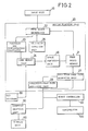
- FIG. 2 there is shown one embodiment of an apparatus for motion planning using free space enumeration according to the present invention.
- This apparatus comprises an input unit 10 for introducing initial position and configuration as well as final position and configuration of a manipulator 100, a motion planning unit 20 for planning a motion for the manipulator 100, a CAD software 30 for assisting the motion planning unit 20, a robot controller 40 for controlling movements of the manipulator 100 in accordance with the motion planned by the motion planning unit 20, a computer graphics unit 50 for preparing computer graphic images of the motion planned by the motion planning unit 20, and a display unit 60 for displaying the computer graphic images prepared by the computer graphics unit 50.
- the motion planning unit 20 further comprises a free space memory 21 for storing and administerring a configuration space defined in terms of degrees of freedom of the manipulator 100 as parameters, a free space enumerator 22 for enumerating a continuous free space containing the initial position and configuration as well as the final position and configuration in the configuration space, a position and configuration calculator 23 for calculating an actual position and configuration of the manipulator 100 in the 2- or 3-dimensional physical space, a form memory unit 24 for memorizing an actual configuration of the manipulator 100 and surrounding obstacles in the physical space at the position and configuration calculated by the position and configuration calculator 23 in accordance with information provided externally from the CAD software 30, a collision detection unit 25 for detecting collisions between the manipulator 100 and the surrounding obstacles in the actual configuration memorized by the form memory unit 24, a space partition unit 26 for determining appropriate quantization of the configuration space in terms of cells, a collision-free path searching unit 27 for deriving a path in the configuration space for the manipulator 100 to move from the initial position and configuration to the final position and configuration
- Fig. 3 shows the 2-dimensional configuration space for the manipulator 100 with two joints whose joint angles are represented by the vertical and horizontal axes where each joint angle is divided up into one hundred equal parts, the partition defined by these divisions defining the cells.
- the black cells are those positions and configurations in which the manipulator 100 collides with the surrounding obstacles, whereas the white cells are those belonging to the free space (referred hereafter as free space cells).
- the collision-free path in this configuration space for the motion of the manipulator 100 between the initial point A and the final point B is to be found out. It is to be noted here that, initially, when only the initial point A and the final point B are given, which cells are the free space cells and which cells are not is largely unknown.
- the free space enumerator 22 utilizes the partition of the configuration space stored in the free space memory 21 as well as occurrence of collisions detected by the collision detection unit 25 in enumerating the free space.
- the cells joining the cell containing the initial point (referred hereafter as an initial cell) and the cell containing the final point (referred hereafter as a final cell) are searched under the assumption that those cells which are not known for certain to be a part of the free space are to be regarded as free space cells. This is done by selecting one adjacent free space cell of a free space cell, successively, starting from the initial cell. This operation is called a cell expansion.
- the direction of searching is immaterial, and can be suitably chosen to be starting either from the initial point, the final point, or both(bi-directional).
- the initial point A in the configuration space is memorized by the free space memory 21 as an unexpanded cell, at the step 101.
- the process terminates as the collision-free path between the initial point A and the final point B is obtained. Otherwise, at the step 103, one unexpanded cell is selected out by the collision-free path searching unit 27. This will be the initial cell at a first time.
- the cell expansion is carried out by the free space enumerator 22 with respect to the unexpanded cell selected at the step 103.
- the free space enumerator 22 For example, in the 2-dimensional configuration space of Fig. 3, four cells neighboring the initial cell are selected as candidates, and each of these four cells are checked by the collision detection unit 25 to see whether these cells are indeed free space cells.
- the collision detection by the collision detection unit 25 can readily be accomplished by using a known algorithm which utilizes the fact that convex polygonal figure can be described as a product set of half spaces. Namely, the collision detection for two convex polygonal figures is carried out by determining whether each vertex of one polygonal figure is located in the opposite side with respect to each face of the other polygonal figure.
- the free space memory 21 memorizes the states of the cells as free space cells already expanded, unexpanded free space cells, cells already checked to cause a collision, and cells not yet checked at the step 105, and the process returns to the step 102.
- the free space enumerator 22 picks out one adjacent free space cell from the candidate cells in accordance with a heuristic function at the step 103.
- h G x ⁇ ⁇ a(i) x [c(i)- Fc(i)]2 (2)
- G is an overall coefficient
- a(i) is an i-th coefficient
- c(i) is an i-th coordinate value of the candidate cell
- Fc(i) is an i-th coordinate value of the final point B, of which the overall coefficient G and, coefficients a(i) are to be prescribed.
- Different prescription gives different strategies for the collision-free path search. This point will be further explored in below. This heuristic function is evaluated for each candidate cell and the one minimizing the heuristic function will be selected as a next unexpanded cell.
- the collision-free path searching unit 27 searches a collision-free path within the enumerated free space cells.
- Fig. 5 The result of this operation is shown in Fig. 5, where a region around the expanded cells are excerpted, with the path given by those cells which are successively selected as a starting unexpanded cell in the cell expansions is indicated as shadowed cells.
- Fig. 6 These expanded cells over the entire configuration space is also shown in Fig. 6. As can be seen from Fig. 6, only a part of the entire configuration space is relevant in searching the path.
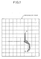
- the entire configuration space is divided up into one hundred blocks, each block containing one hundred cells, as shown in Fig. 7, and only those blocks which contains the expanded cells are allocated with the memory address in the free space memory 21, accompanied by the labelling number.
- those blocks having the memory space allocated are so indicated by being given the labelling numbers appearing as encircled numerals, whereas the others are given crosses to indicate that these others are not allocated with the memory address.
- the free space memory 21 only those blocks with the labelling numbers given are stored, as shown in Fig. 9. Because of this, the memory space in the free space memory 21 to be utilized in this embodiment can be kept small.
- the collision-free path is modified by the collision-free path modifying unit 28.
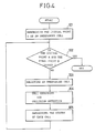
- the operation of this collision-free path modifying unit 28 will now be explained along the flow chart of Fig. 10.
- the collision-free path modifying unit 28 utilizes a method called wavefront expansion, so called because of the analogy to the radially outgoing wave propagation caused by dropping a stone on the water surface.
- wavefront expansion the additional free space is enumerated from the given path by expanding the boundary of the free space in four directions of the neighboring cells in a case of 2-dimensional configuration space.
- the collision-free path obtained by the collision-free path searching unit 27, shown in Fig. 11 comes to the collision-free path modifying unit 28 at the step 201, the enumeration of the additional free space is carried out at the step 202 by performing the wavefront expansion with respect to the path in three-fold, as shown in Fig. 12.
- the expansion will not be continued in a direction in which the edge of the free space (wavefront) reaches the collision cells, as soon as this happens.
- the wavefront expansion is carried out, in three-fold again, with respect to the collision cells located nearby the collision-free path within the free space enumerated at the step 202, as shown in Fig. 13, in order to find out dangerous cells which are free space cells too closely located nearby the collision cells.
- the collision-free path is searched within the free space excluding the dangerous cells found at the step 204, as shown in Fig. 14, to obtain the modified collision-free path at the step 205.
- First way is to utilize local neighborhood operations using a scanning window. This way is closely related to the local neighborhood operations for differentiation and smoothing in the image processing.
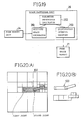
- FIG. 15 An example of the scanning window is shown in Fig. 15, where the scanning window 110 comprises a part for a central cell 111 surrounded by parts for its four neighbors 112 to 115 in four different directions.
- This scanning window 110 scans the entire configuration space, as shown in Fig. 16.
- the wavefront does not cover the central cell part 111, but does so for at least one of the surrounding parts 112 to 115, then the wavefront is expanded so as to cover the central cell part 111.
- the wavefront does cover the central part 111, or when the wave front does not cover any part of the scanning window 110, no wavefront expansion takes place.
- the scanning by the scanning window 110 can be repeated several times.
- Second way is to utilize a evaluation value in determining cells to be expanded. This way resembles the method for the cell expansions explained above.
- each cell on the collision-free path is stored in the candidate memory with a evaluation value of 0 attached.
- the evaluation value indicate a number of wavefront expansion performed in obtaining that cell, so that the evaluation value 0 indicates that this cell is obtained without performing any wavefront expansion.
- one cell in the candidate memory which has the lowest evaluation value is selected out as a candidate cell with respect to which the wavefront expansion is to be performed.
- the selection is made arbitrary. This process of selecting the candidate cell may be facilitated by arranging the cells in the candidate memory in order of the increasing evaluation value. Also, the selected candidate cell is deleted from the candidate memory at this point.
- step 303 whether the operation is finished is determined. When this is the case, the operation terminates as it should, and otherwise the step 304 will be taken.
- the wavefront expansion is performed with respect to the selected candidate cell such that the wavefront will cover those neighboring cells of the candidate cell which has net been covered by the wavefront.
- the neighboring cells of the candidate cell are, for example in the 2-dimensional configuration space, those cells adjacent to the candidate cell in four directions of right, left, up, and down.
- the neighboring cells which became to be covered by the wavefront as a result of this wavefront expansion at the step 304 are then stored in the candidate memory with the evaluation value of 1 attached, at the step 305.
- the operation then returns to the step 302, and will be repeated until the wavefront expansion is finished.
- the cells with the evaluation value 0 will be completely deleted from the candidate memory, so that the cells with the evaluation value 1 can be the candidate cells in the next cycle of the operation.
- the operation can be terminated as soon as the cell with the evaluation value 3 is selected as the candidate cell.
- the operation just described may be further modified by memorizing those free space cells which are being covered by the wave front as such. Also, the evaluation values assigned to each free space cells can be useful in performing the wavefront expansion from the collision cells as an indicators of dangerousness. Such an information can be useful in controlling the speed of the manipulator 100 such that the manipulator 100 moves slowly in passing near the obstacles.
- the wavefront expansion is carried out in three-fold, which is appropriate for the 2-dimensional configuration space
- the three-fold wavefront expansion can be too time consuming, and that in such a case the reduction of the wavefront expansion from three-fold to two-fold has been found to be effective in the trials administered by the present applicant.
- the further wavefront expansion may be performed from the modified collision-free path. Such alternation of wavefront expansion and the collision-free path modification can be repeated as many times as necessary for the desired standard.
- obtaining the less dangerous collision-free path can also be furnished by adjusting the normalised distance c in the heuristic function f utilized above in obtaining the collision-free path by the collision-free path searching unit 27, such that this normalised distance c also reflects the dangerousness of the cells in the collision-free path. For instance, for cells adjacent to the collision cells the value of c can be weighted down by adding 9, for cells in next fold by 4, and cells in next next fold by 1. This will yield the same collision-free path as that obtained above by the collision-free path modifying unit 28, shown in Fig. 14.
- this feature of the collision-free path modifying unit 28 enable this embodiment to obtain the collision-free path which is much more practical and less dangerous, with minimum sacrifice in efficiency of the motion of the manipulator 100.
- This feature of the collision-free path modifying unit 28 is also very advantageous in applications of this embodiment other than the motion planning for the manipulator 100.
- CAD computer aided designing
- space enumeration system to assist designing.
- An example of this can be found in CAD for designing piping in a factory in which appropriate types and arrangement of piping in different areas of the factory are deduced from the conditions on pipes, available spaces and cost.
- this embodiment can be successfully applied to such space enumeration system by using real space coordinates as degrees of freedom defining the configuration space.
- the enumeration of the additional free space is carried out at the step 402 by performing the wavefront expansion with respect to this available space in three-fold.
- the expansion will not be continued in a direction in which the edge of the free space (wavefront) reaches the region not satisfying the conditions, as soon as this happens.
- the wavefront expansion is carried out, in three-fold again, with respect to the region not satisfying the conditions located nearby the available space within the free space enumerated at the step 402, in order to find out dangerous cells which are free space cells too closely located nearby the region not satisfying the conditions.
- the available space is searched within the free space excluding the dangerous cells found at the step 404 to obtain the modified available space at the step 405.
- this space partition unit 26 determines appropriate partition of the configuration space in terms of cells and arrangement of partitioning cells.
- the space partition unit 26 further comprises an occupied space enumerator 261 for enumerating actual physical space occupied by the manipulator 100 in accordance with the actual configuration of the manipulator 100 and surrounding obstacles in the physical space at the position and configuration calculated by the position and configuration calculator 23 stored in the form memory unit 24, a parameter dependence calculator 262 for deriving parameter dependences of the occupied space as differences between the occupied space obtained with one parameter changed by one unit of a given configuration space quantization interval, and a quantization interval modifier 263 for adjusting the quantization interval of the configuration space in accordance with results of comparison between the parameter dependences and the prescribed value.
- the quad-tree is a way of representing the 2-dimensional plane first by a large square, then dividing this square in four equal squares, and so on, as shown in Fig. 20(A) where those squares which contains at least a part of the manipulator 100 is shadowed.
- dividing square continues until sufficiently fine sub-divisions are obtained for the sake of ample approximation of the configuration of the manipulator 100 by the sub-divided squares.
- the particular configuration of the manipulator 100 is represented by three larger squares and four smaller squares, as shown in Fig. 20(B).
- the oct-tree is an equivalent method of the quad-tree in 3-dimension comprising a successive sub-division of a cube into eight cubes. It is to be noted that Fig. 20 does not depict the configuration space, but the actual physical space.
- Fig. 21 the manipulator 100 with two joints is shown with uniform quantization, where the rectangles containing the manipulator 100 are shown as shadowed. It is to be noted that Fig. 21 also does not depict the configuration space, but the actual physical space.
- FIG. 22(A) depicts this manipulator 100 with its two joints straightened. In this case, there are eighteen rectangles containing the manipulator 100 as shown in Fig. 22(A).
- Fig. 22(B) depicts the manipulator 100 when only the second joint is moved by one unit of the quantization interval.
- the parameter dependence of the second joint is 3.
- Fig. 22(C) depicts the manipulator 100 when only the first joint is moved by one unit of the quantization interval.
- the parameter dependence of the first joint is 7.
- the parameter dependences may also be evaluated with respect to a limited part of the manipulator 100, such as just with respect to the second joint, regardless of the state of the first joint.
- the quantization interval modifier 263 adjusts the quantization interval of the configuration space in accordance with results of comparison between the parameter dependences and the prescribed value.
- the prescribed value indicates a desirable value for parameter dependences. For example, in the above example of parameter dependences obtained from Fig. 22, if the desirable value for the parameter dependences is given as 3, then the facts that the second joint already has the desirable parameter dependence, but the first joint doesn't will be found out by the quantization interval modifier 263 upon comparison with respect to that prescribed value of 3. Subsequently, the quantization interval for the second joint angle will be unchanged, but that for the first joint angle will be modified to be three seventh of what is was before.
- the collision-free path search for the situation of the configuration space shown in Fig. 23 where A and B are the initial and final points, respectively, as before, was performed with three different strategies.
- plurality of different strategies are used simultaneously in each collision-free path search. Then, either searches by less efficient strategies are stopped when the most efficient strategy finish its search, or less efficient strategies are detected and dropped in the course of searching by inspections at intermediate moments.
- the collision-free path search was performed for a particular motion of a manipulator with six degree of freedom shown in Fig. 30 in sequential order, in which the initial and final configurations are as shown in Fig. 31(A) and (B), respectively.
- the range for the coefficients a(i) is independently set for each coefficient a(i) such that the range is narrower for a coefficient with smaller difference between the initial point and the final point.
- This equation (3) gives a range between 1 and 3 for a coefficient which has the same value at the initial point and final point, whereas for a coefficient with the largest difference between the initial point and the final point a range between 1 and 9 will be obtained.
- the trials of 300 free space enumeration similar to the above with these ranges for the coefficients a(i) yielded the histogram shown in Fig. 32 which also shows the distribution among 300 trials of free space enumeration in number of the collision detections performed. As can be seen from Fig. 33, the number of the free space enumeration requiring large numbers of the collision detections to be performed decreased in this case, compared with the previous case of Fig. 32.
- (4) or, r(i) 3 + 6 x ⁇
- Fig. 35 shows changes of each of six joint angles in time sequence.
- Figs. 39, 40, and 41 The histograms showing the distributions among 300 trials of free space enumeration in number of the collision detections performed, corresponding to Fig. 32 of the previous example, for these three cases of Figs. 36, 37, and 38 are shown in Figs. 39, 40, and 41, respectively. As can be seen from Figs. 39, 40, and 41, more often only small numbers of collision detections are called for in all of these three cases.
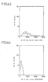
- Figs. 42, 43, and 44 The similar histograms obtained by the multi-strategical procedure using four different strategies simultaneously, corresponding to Fig. 34 of the previous example, are shown in Figs. 42, 43, and 44, respectively.
- Figs. 42, 43, and 44 all shows that the multi-strategical procedure is at least as effective as the single procedure, if not more.
- Fig. 46 shows that the fifth joint have to be moved away from the final position at a time, and the sixth joint angle have to go through rather quick and large changes.
- the free space can be very complicated so that the free space enumeration needs to cover a widely spread regions.
- the obstacles tend to limit the spread of the regions to be covered in the free space enumeration by their sheet presence, so that the fluctuation in the number of the collision detections to be performed in this case chiefly comes from the complexity of the physical configuration. This accounts for rather wide fluctuation shown in both Figs. 43 and 46.
- P C N /F (6)
- C is a number of cells from the initial point to the point
- N is a dimensionality of the configuration space
- F is a total number of cells in the free space already enumerated for reaching the point.
- This quantity P is calculated whenever the collision detection for a cell is performed, and the efficiencies are estimated at intermediate moments as an average of the quantities P for last several collision detections. Also, the rate of expansions of cells in the free space enumeration are slowed down in accordance with the efficiencies as they are estimated, so that the free space enumerations by inefficient strategies do not proceed too far before the most efficient strategy finish its free space enumeration.
- the efficiency P i (j) of i-th strategy in that j-th search is determined as an average of the quantity P for last NP cells expanded in that j-th search by the i-th strategy, where NP is a prescribed number.
- the the number NE i (j) of expansions to be carried out is then defined in terms of this efficiency P i (j) be the expression: so that although the searches start out for all the strategies in a similar fashion, the free space enumerations by inefficient strategies do not proceed too far before the most efficient strategy finish its free space enumeration.
- the useless searches by the inefficient strategies can be spared, and the tendency for the search region to be widened in the multi-strategical search compared with single strategy search can be suppressed.
- the motion planning using free space enumeration it is possible for the motion planning using free space enumeration to have general applicability to various types of moving objects, and at a same time capable of reducing amounts of information and calculations involved in obtaining motion for objects with multiple degrees of freedom, because of the particular manner of enumerating free space and searching collision-free path.
- the motion planning using free space enumeration to be capable of modifying a path and a space obtained in a simplified manner to be more practical ones, because of the collision-free path modifying unit 28.
- the motion planning using free space enumeration it is possible for the motion planning using free space enumeration to be capable of setting up appropriate configuration space partitions for different parameters of the configuration space automatically, because of the space partition unit 26.
- the motion planning using free space enumeration it is possible for the motion planning using free space enumeration to be capable of adopting appropriate strategy for free space enumeration in accordance with a type of a moving object and environmental conditions of the moving object, because of the particular manner the free space enumeration is to be performed.
Abstract
Description
- The present invention relates to a method and an apparatus of free space enumeration for collision avoidance, which have a primary application in the field of motion plnning of robot manipulators, to be utilized in obtaining a collision-free path in which a moving object such as a manipulator can move without a collision with surrounding objects. The method and the apparatus can also be utilized beneficially as a space enumerator in designing an optimal arrangement of various apparatuses, of piping in factory, and of electronic circuitry.
- For a motion planning of a moving object such as a manipulator between given initial position and configuration, and given final position and configuration, where a path capable of avoiding collisions with surrounding obstacles is sought, a use of a so called configuration space of N-dimension parametrically defined in terms of N-degrees of freedom for the manipulator's position and configuration has been considered effective.
- In this type of motion planning, there is a one-to-one correspondence between a point of the configuration space and a unique position and configuration of the manipulator, so that the path of the manipulator capable of avoiding collisions with surrounding obstacles, which can easily be highly complicated in 3-dimensional physical space, can be represented by a simple trajectory of the point of the configuration space through a collision free region of the configuration space called a free space.
- An example of such a configuration for a manipulator and obstacles shown in Fig. 1(A) is shown in Fig. 1(B), where a vertical axis represents angle of third joint of the manipulator, and a horizontal axis represents angle of second joint of the manipulator. The 3-dimensional physical configuration shown in Fig. 1(A) is represented by the configuration space shown in Fig. 1(B) in which those values of the second and the third joint angles that causes collisions between the manipulator and the obstacles are shown as a block of black cells (named as a collision cells in the figure), with the remaining free space surrounding it. Thus, for the manipulator to move from an initial configuration represented by a cell A to a final configuration represented by another cell B without colliding with obstacles, a path has to be chosen to go around the collision cells.
- Since the configuration space, in general, is divided up into a multiplicity of small regions called cells, it is necessary to determine which cells belong to the free space. Although, in principle, this can easily be accomplished by performing collision detections between the manipulator and the obstacles, a progressive increase in amounts of information to be dealt with accompanying an increase in dimensionality imposes a limit to an extent to which the collision detections can be carried out.
- For instance, a manipulator with 6 degrees of freedom calls for a 6-dimensional configuration space, and when each of the 6 coordinates is to be divided up (or quantized) into 32 equal parts in order to define cells, the number of cells becomes a sixth power of 32, which makes a practical implementation of complete collision detections for all the cells almost impossible.
- Thus, in practice a reduction of an amount of information is indispensable.
- One known way of achieving this is by considering only those degrees of freedom having major contribution to the motion in accordance with the functional characteristics of the manipulator, and thereby reducing the dimensionality of the configuration space. For example, when the motion of a manipulator with six degrees of freedom can largely be determined by three of those six degrees of freedom related to the main arm alone, the motion of this manipulator may effectively be described by the 3-dimensional configuration space using only three degrees of freedom related to the main arm. However, this way of reducing the amount of information requires a knowledge of those degree of freedom having major contribution to the motion, which have to be decided case by case, so that not only the preparation for such motion planning becomes cumbersome, but also the general applicability of this type of motion planning is severely restricted.
- Another known way of achieving the reduction of the amount of information is, as discussed by the present applicant in "collision avoidance using free space enumeration method based on Lee's algorithm" on Journal of Robotics Society of Japan, Vol.5, no.4, pp.11-20, 1987, to limit the free space to just a region relevant in obtaining the path. However, in such a conventional motion planning, in order to achieve the reduction of the amount of information, the path has been determined disrespectful of ease in motion, so that practically dangerous paths such as those which are nearly grazing the obstacle have often been resulted. Furthermore, this manner of reducing the amount of information is based on a method called wavefront expansion, which will be explained in detail below, so that the reduction cannot be sufficient for those cases involving six degrees of freedom.
- Likewise, in the application of the free space enumerator to designing of an optimal arrangement of various apparatuses, of piping in factory, and of electronic circuitry, practically dangerous spaces such as those in the immediate vicinity of the obstacles have often been obtained.
- As explained, in conventional methods for motion planning, an enormous amount of information required in performing a complete collision detections cannot be suppressed without sacrificing either the general applicability of the methods or the practicality of the path or the space to be obtained.
- Furthermore, there is another problem in the conventional methods for motion planning, concerning the manner of quantizing the coordinates of the configuration space. Namely, when the coordinates of the configuration space are quantized by the same interval throughout as in the conventional methods, due to the differences in significance with respect to the whole motion possessed by different degree of freedom, the quantization may be unnecessarily fine for some such as a main arm portion and too coarse to obtain a sufficient accuracy for the other such as a finger portion. The unnecessarily fine quantization causes a drastic increase in the amount of information to be dealt with, which in turn causes a tremendous elongation of the operation time. On the other hand, the insufficient accuracy due to the coarse quantization may cause an overlooking of small obstacle such as a thin wire.
- In addition, the conventional methods for motion planning are associated with yet another problem in determination of the free space cells. Since there are many different types of manipulators with different types of degrees of freedom, and also since the changes in environmental conditions of the manipulator delicately affect the state of the configuration space, the method of determining the free space cells in the configuration space have to be chosen carefully, in order for the method to be effective.
- However, it is extremely difficult to select out an appropriate method for determining the free space cells, as the state of the configuration space is generally not known, and also as it is impossible to deal with all the information on the configuration space. The choice of an inappropriate method for determining the free space cells results in very inefficient operation and all the inconveniences caused by such operation.
- It is therefore an object of the present invention to provide a method and an apparatus of free space enumeration for motion planning, having general applicability to various types of moving objects, and at a same time capable of reducing amounts of information and calculations involved in obtaining motion for objects with multiple degrees of freedom.
- Another object of the present invention is to provide a method and an apparatus of free space enumeration for motion planning, capable of modifying a path and a space obtained in a simplified manner to be more practical ones.
- Another object of the present invention is to provides method and an apparatus of free space enumeration for motion planning, capable of setting up appropriate configuration space quantization for different parameters of the configuration space automatically.
- Another object of the present invention is to provide a method and an apparatus of free space enumeration for motion planning, capable of adopting appropriate strategy for free space enumeration in accordance with a type of a moving object and environmental conditions of the moving object.
- According to one aspect of the present invention there is provided an apparatus for enumerating a free space in a configuration space representing configurations of an object and surrounding obstacles in terms of degrees of freedom of the object, the configuration space being divided up into multiplicity of cells defined in terms of intervals in the degrees of freedom, the free space being continuously connecting a given initial point in the configuration space from which a motion of the object starts and a given final point in the configuration space at which the motion ends, the apparatus comprising: means for selecting cells only between the initial point and the final point; means for detecting a collision between the object and the surrounding obstacles in the selected cells; and means for memorizing positions in the configuration space of free space cells which are the selected cells for which the collision cannot be detected.
- According to another aspect of the present invention there is provided an apparatus for enumerating a free space in a configuration space representing configurations of an object and surrounding obstacles in terms of degrees of freedom of the object, the configuration space being divided up into multiplicity of cells defined in terms of intervals in the degrees of freedom, the free space being continuously connecting a given initial point in the configuration space from which a motion of the object starts and a given final point in the configuration space at which the motion ends, the apparatus comprising: means for selecting cells between the initial point and the final point, using plurality of strategies for selecting the cells simultaneously; and means for detecting a collision between the object and the surrounding obstacles in the selected cells.
- Another to another aspect of the present invention there is provided an apparatus for enumerating a free space in a configuration space representing configurations of an object and surrounding obstacles in terms of degrees of freedom of the object, the free space being continuously connecting a given initial point in the configuration space from which a motion of the object starts and a given final point in the configuration space at which the motion ends, the apparatus comprising: means for dividing the configuration space into multiplicity of cells defined in terms of intervals in the degrees of freedom, including: means for partitioning a physical space into multiplicity of sub-regions; means for calculating a change in a total volume of the sub-regions which contains at least a portion of the object when each one of the degrees of freedom is varied separately by one provisional unit of intervals; and means for determining the intervals for the degrees of freedom defining the cells in the configuration space in accordance with the calculated change; means for selecting cells between the initial point and the final point; and means for detecting a collision between the object and the surrounding obstacles in the selected cells.
- According to another aspect of the present invention there is provided an apparatus for motion planning using free space enumeration, in which configurations of an object and surrounding obstacles are represented by a configuration space defined in terms of degrees of freedom of the object, the configuration space being divided up into multiplicity of cells defined in terms of intervals in the degrees of freedom, in which a motion of the object between a given initial point in the configuration space from which the motion starts and a given final point in the configuration space at which the motion ends is to be planned, the apparatus comprising: means for enumerating a continuous free space between the initial point and the final point, in which the motion is possible, including: means for selecting cells only between the initial point and the final point; means for detecting a collision between the object and the surrounding obstacles in the selected cells; and means for memorizing positions in the configuration space of free space cells which are the selected cells for which the collision cannot be detected; and means for determining a collision-free path in the free space joining the initial point and the final point without the collision.
- According to another aspect of the present invention there is provided an apparatus for motion planning using free space enumeration, in which configurations of an object and surrounding obstacles are represented by a configuration space defined in terms of degrees of freedom of the object, the configuration space being divided up into multiplicity of cells defined in terms of intervals in the degrees of freedom, in which a motion of the object between a given initial point in the configuration space from which the motion starts and a given final point in the configuration space at which the motion ends is to be planned, the apparatus comprising: means for enumerating a continuous free space between the initial point and the final point, in which the motion is possible: means for determining a collision-free path in the free space joining the initial point and the final point without the collision; and means for modifying the collision-free path.
- According to another aspect of the present invention there is provided a method for enumerating a free space in a configuration space representing configurations of an object and surrounding obstacles in terms of degrees of freedom of the object, the configuration space being divided up into multiplicity of cells defined in terms of intervals in the degrees of freedom, the free space being continuously connecting a given initial point in the configuration space from which a motion of the object starts and a given final point in the configuration space at which the motion ends, the method comprising the steps of: selecting cells only between the initial point and the final point; detecting a collision between the object and the surrounding obstacles in the selected cells; and memorizing positions in the configuration space of free space cells which are the selected cells for which the collision cannot be detected.
- According to another aspect of the present invention there is provide a method for enumerating a free space in a configuration space representing configurations of an object and surrounding obstacles in terms of degrees of freedom of the object, the configuration space being divided up into multiplicity of cells defined in terms of intervals in the degrees of freedom, the free space being continuously connecting a given initial point in the configuration space from which a motion of the object starts and a given final point in the configuration space at which the motion ends, the method comprising the steps of: selecting cells between the initial point and the final point, using plurality of strategies for selecting the cells simultaneously; and detecting a collision between the object and the surrounding obstacles in the selected cells.
- According to another aspect of the present invention there is provided a method for enumerating a free space in a configuration space representing configurations of an object and surrounding obstacles in terms of degrees of freedom of the object, the free space being continuously connecting a given initial point in the configuration space from which a motion of the object starts and a given final point in the configuration space at which the motion ends, the method comprising the steps of: dividing the configuration space into multiplicity of cells defined in terms of intervals in the degrees of freedom, including the steps of: partitioning a physical space into multiplicity of sub-regions; calculating a change in a total volume of the sub-regions which contains at least a portion of the object when each one of the degrees of freedom is varied separately by one provisional unit of intervals; and determining the intervals for the degrees of freedom defining the cells in the configuration space in accordance with the calculated change; selecting cells between the initial point and the final point; and detecting a collision between the object and the surrounding obstacles in the selected cells.
- According to another aspect of the present invention there is provided a method for motion planning using free space enumeration, in which configurations of an object and surrounding obstacles are represented by a configuration space defined in terms of degrees of freedom of the object, the configuration space being divided up into multiplicity of cells defined in terms of intervals in the degrees of freedom, in which a motion of the object between a given initial point in the configuration space from which the motion starts and a given final point in the configuration space at which the motion ends is to be planned, the method comprising the steps of: enumerating a continuous free space between the initial point and the final point, in which the motion is possible, including the steps of: selecting cells only between the initial point and the final point; detecting a collision between the object and the surrounding obstacles in the selected cells; and memorizing positions in the configuration space of free space cells which are the selected cells for which the collision cannot be detected; and determining a collision-free path in the free space joining the initial point and the final point without the collision.
- According to another aspect of the present invention there is provided a method for motion planning using free space enumeration, in which configurations of an object and surrounding obstacles are represented by a configuration space defined in terms of degrees of freedom of the object, the configuration space being divided up into multiplicity of cells defined in terms of intervals in the degrees of freedom, in which a motion of the object between a given initial point in the configuration space from which the motion starts and a given final point in the configuration space at which the motion ends is to be planned, the method comprising the steps of: enumerating a continuous free space between the initial point and the final point, in which the motion is possible; determining a collision-free path in the free space joining the initial point and the final point without the collision; and modifying the collision-free path.
- Other features and advantages of the present invention will become apparent from the following description taken in conjunction with the accompanying drawings.
-
- Fig. 1(A) and (B) are illustrations of a manipulator with surrounding obstacles and a corresponding configuration space, respectively, for explaining the relationship between the physical configuration and the corresponding configuration space.
- Fig. 2 is a schematic block diagram of one embodiment of an apparatus for motion planning using free space enumeration according to the present invention.
- Fig. 3 is an illustration of an example of the configuration space to be utilized by the apparatus of Fig. 2.
- Fig. 4 is a flow chart for the operation of free space enumeration by the apparatus of Fig. 2.
- Fig. 5 is an illustration of the configuration space of Fig. 3 showing in addition the result of the free space enumeration and the collision-free path search by the apparatus of Fig. 2.
- Fig. 6 is an illustration of the configuration space of Fig. 3, showing in particular the free space enumerated by the apparatus of Fig. 2.
- Fig. 7 is an illustration of the configuration space of Fig. 3, showing in particular the free space enumerated by the apparatus of Fig. 2 along with partitions of the configuration space.
- Fig. 8 is a diagrammatic illustration of blocks in the configuration space of Fig. 3, for explaining the manner of memorizing the free space by the apparatus of Fig. 2.
- Fig. 9 is a diagrammatic illustration of a free space memory unit of the apparatus of Fig. 2, for explaining the manner of memorizing the free space by the apparatus of Fig. 2.
- Fig. 10 is a flow chart for the operation of collision-free path modification by the apparatus of Fig. 2.
- Fig. 11 is an illustration of the free space enumerated and the collision-free path found, for explaining the manner of collision-free path modification by the apparatus of Fig. 2.
- Fig. 12 is an illustration of the free space expanded and the collision-free path found, for explaining the manner of collision-free path modification by the apparatus of Fig. 2.
- Fig. 13 is an illustration of the free space expanded and the collision-free path found, showing in particular dangerous cells, for explaining the manner of collision-free path modification by the apparatus of Fig. 2.
- Fig. 14 is an illustration of the free space expanded and the modified collision-free path, for explaining the manner of collision-free path modification by the apparatus of Fig. 2.
- Fig. 15 is an illustration of a scanning window to be utilized for the expansion of free space by the apparatus of Fig. 2.
- Fig. 16 is an illustration of the scanning window of Fig. 15 on the configuration space, for explaining the manner of utilizing the scanning window in the expansion of free space by the apparatus of Fig. 2.
- Fig. 17 is a flow chart for wavefront expansion to be performed by the apparatus of Fig. 2.
- Fig. 18 is a flow chart for the operation of free space enumeration and collision-free path search by the apparatus shown in Fig. 2, in the application to the designing by CAD system.
- Fig. 19 is a detail block diagram of a space partition unit of the apparatus of Fig. 2.
- Fig. 20(A) and (B) are illustrations of the manipulator in the physical space and its decomposition, for explaining the operation of space partition by the apparatus of Fig. 2.
- Fig. 21 is an illustration of the manipulator in the physical space and its decomposition, for explaining the operation of space partition by the apparatus of Fig. 2.
- Fig. 22(A), (B) and (C) are illustrations of the manipulator in the physical space and its decomposition at different configuration, for explaining the operation of space partition by the apparatus of Fig. 2.
- Fig. 23 is an illustration of an example of the configuration space to be used for explaining the manner of collision-free path search by the apparatus of Fig. 2.
- Fig. 24 is an illustration of free space enumerated for the configuration space of Fig. 23 by the apparatus of Fig. 2, for explaining the manner of collision-free path search by the apparatus of Fig. 2.
- Fig. 25 is an illustration of free space enumerated for the configuration space of Fig. 23 by the apparatus of Fig. 2, for explaining the manner of collision-free path search by the apparatus of Fig. 2.
- Fig. 26 is an illustration of free space enumerated for the configuration space of Fig. 23 by the apparatus of Fig. 2, for explaining the manner of collision-free path search by the apparatus of Fig. 2.
- Fig. 27 is an illustration of free space enumerated for the configuration space of Fig. 23 by the apparatus of Fig. 2, for explaining the manner of collision-free path search by the apparatus of Fig. 2.
- Fig. 28 is an illustration of free space enumerated for the configuration space of Fig. 23 by the apparatus of Fig. 2, for explaining the manner of collision-free path search by the apparatus of Fig. 2.
- Fig. 29 is an illustration of free space enumerated for the configuration space of Fig. 23 by the apparatus of Fig. 2, for explaining the manner of collision-free path search by the apparatus of Fig. 2.
- Fig. 30 is a sequential illustrations of the manipulator showing an example of motion to be planned by the apparatus of Fig. 2.
- Fig. 31(A) and (B) are illustration of an initial and final configuration of the manipulator in the motion shown in Fig. 30.
- Fig. 32 is a histogram showing the distribution of the number of collision detections to be performed by different strategy of free space enumeration for the configuration of Fig. 31 by the apparatus of Fig. 2.
- Fig. 33 is a histogram showing the distribution of the number of collision detections to be performed by different strategy of free space enumeration by the apparatus of Fig. 2.
- Fig. 34 is a histogram showing the distribution of the number of collision detections to be performed by different strategy of free space enumeration by the apparatus of Fig. 2.
- Fig. 35 is a graph showing the collision-free path found for the configuration of Fig. 31 by the apparatus of Fig. 2.
- Fig. 36(A) and (B) are illustration of an initial and final configuration of the manipulator in the motion to be planned by the apparatus of Fig. 2.
- Fig. 37(A) and (B) are illustration of an initial and final configuration of the manipulator in the motion to be planned by the apparatus of Fig. 2.
- Fig. 38(A) and (B) are illustration of an initial and final configuration of the manipulator in the motion to be planned by the apparatus of Fig. 2.
- Fig. 39 is a histogram showing the distribution of the number of collision detections to be performed by different strategy of free space enumeration for the configuration of Fig. 36 by the apparatus of Fig. 2.
- Fig. 40 is a histogram showing the distribution of the number of collision detections to be performed by different strategy of free space enumeration for the configuration of Fig. 37 by the apparatus of Fig. 2.
- Fig. 41 is a histogram showing the distribution of the number of collision detections to be performed by different strategy of free space enumeration for the configuration of Fig. 38 by the apparatus of Fig. 2.
- Fig. 42 is a histogram showing the distribution of the number of collision detections to be performed by different strategy of free space enumeration for the configuration of Fig. 36 by the apparatus of Fig. 2.
- Fig. 43 is a histogram showing the distribution of the number of collision detections to be performed by different strategy of free space enumeration for the configuration of Fig. 37 by the apparatus of Fig. 2.
- Fig. 44 is a histogram showing the distribution of the number of collision detections to be performed by different strategy of free space enumeration for the configuration of Fig. 38 by the apparatus of Fig. 2.
- Fig. 45 is a graph showing the collision-free path found for the configuration of Fig. 36 by the apparatus of Fig. 2.
- Fig. 46 is a graph showing the collision-free path found for the configuration of Fig. 37 by the apparatus of Fig. 2.
- Fig. 47 is a graph showing the collision-free path found for the configuration of Fig. 38 by the apparatus of Fig. 2.
- Referring now to Fig. 2, there is shown one embodiment of an apparatus for motion planning using free space enumeration according to the present invention.
- This apparatus comprises an
input unit 10 for introducing initial position and configuration as well as final position and configuration of amanipulator 100, amotion planning unit 20 for planning a motion for themanipulator 100, aCAD software 30 for assisting themotion planning unit 20, arobot controller 40 for controlling movements of themanipulator 100 in accordance with the motion planned by themotion planning unit 20, acomputer graphics unit 50 for preparing computer graphic images of the motion planned by themotion planning unit 20, and adisplay unit 60 for displaying the computer graphic images prepared by thecomputer graphics unit 50. - The motion planning unit 20 further comprises a free space memory 21 for storing and administerring a configuration space defined in terms of degrees of freedom of the manipulator 100 as parameters, a free space enumerator 22 for enumerating a continuous free space containing the initial position and configuration as well as the final position and configuration in the configuration space, a position and configuration calculator 23 for calculating an actual position and configuration of the manipulator 100 in the 2- or 3-dimensional physical space, a form memory unit 24 for memorizing an actual configuration of the manipulator 100 and surrounding obstacles in the physical space at the position and configuration calculated by the position and configuration calculator 23 in accordance with information provided externally from the CAD software 30, a collision detection unit 25 for detecting collisions between the manipulator 100 and the surrounding obstacles in the actual configuration memorized by the form memory unit 24, a space partition unit 26 for determining appropriate quantization of the configuration space in terms of cells, a collision-free path searching unit 27 for deriving a path in the configuration space for the manipulator 100 to move from the initial position and configuration to the final position and configuration without a collision, and a collision-free path modifying unit 28 for modifying the collision-free path derived by the collision-free path searching unit 27 to be more practical one.
- Now, the operation of the
free space memory 21, thefree space enumerator 22, thecollision detection unit 25, and the collision-freepath searching unit 27 will be explained for an example of the configuration space shown in Fig. 3, along the flow chart of Fig. 4. Further detail of the other elements of this embodiment will be explained later. - Fig. 3 shows the 2-dimensional configuration space for the
manipulator 100 with two joints whose joint angles are represented by the vertical and horizontal axes where each joint angle is divided up into one hundred equal parts, the partition defined by these divisions defining the cells. The black cells are those positions and configurations in which themanipulator 100 collides with the surrounding obstacles, whereas the white cells are those belonging to the free space (referred hereafter as free space cells). The collision-free path in this configuration space for the motion of themanipulator 100 between the initial point A and the final point B is to be found out. It is to be noted here that, initially, when only the initial point A and the final point B are given, which cells are the free space cells and which cells are not is largely unknown. - The
free space enumerator 22 utilizes the partition of the configuration space stored in thefree space memory 21 as well as occurrence of collisions detected by thecollision detection unit 25 in enumerating the free space. - In short, the cells joining the cell containing the initial point (referred hereafter as an initial cell) and the cell containing the final point (referred hereafter as a final cell) are searched under the assumption that those cells which are not known for certain to be a part of the free space are to be regarded as free space cells. This is done by selecting one adjacent free space cell of a free space cell, successively, starting from the initial cell. This operation is called a cell expansion. Here, the direction of searching is immaterial, and can be suitably chosen to be starting either from the initial point, the final point, or both(bi-directional).
- What is outlined above is actually carried out as follows.
- First, after the initial and final positions and configurations are entered at the
input unit 10, the initial point A in the configuration space is memorized by thefree space memory 21 as an unexpanded cell, at thestep 101. - Then, at the
step 102, whether the initial point A and the final point B is joined is determined by thefree space enumerator 22. - When this is the case, the process terminates as the collision-free path between the initial point A and the final point B is obtained. Otherwise, at the
step 103, one unexpanded cell is selected out by the collision-freepath searching unit 27. This will be the initial cell at a first time. - Next, at the
step 104, the cell expansion is carried out by thefree space enumerator 22 with respect to the unexpanded cell selected at thestep 103. For example, in the 2-dimensional configuration space of Fig. 3, four cells neighboring the initial cell are selected as candidates, and each of these four cells are checked by thecollision detection unit 25 to see whether these cells are indeed free space cells. - The collision detection by the
collision detection unit 25 can readily be accomplished by using a known algorithm which utilizes the fact that convex polygonal figure can be described as a product set of half spaces. Namely, the collision detection for two convex polygonal figures is carried out by determining whether each vertex of one polygonal figure is located in the opposite side with respect to each face of the other polygonal figure. - The
free space memory 21 memorizes the states of the cells as free space cells already expanded, unexpanded free space cells, cells already checked to cause a collision, and cells not yet checked at thestep 105, and the process returns to thestep 102. - From the second time on, the
free space enumerator 22 picks out one adjacent free space cell from the candidate cells in accordance with a heuristic function at thestep 103. An example of the heuristic function is a function f given by:
f = c + h (1)
where c is a normalized distance given in terms of a number of cells from the initial cell, and h is a estimated distance to the final cell which can, for instance, be set equal to twice the length of the straight line to the final point B. More sophisticated way to derive the estimated distance h is according to the following equation:
h = G x √Σ a(i) x [c(i)- Fc(i)]² (2)
where G is an overall coefficient, a(i) is an i-th coefficient, c(i) is an i-th coordinate value of the candidate cell, Fc(i) is an i-th coordinate value of the final point B, of which the overall coefficient G and, coefficients a(i) are to be prescribed. Different prescription gives different strategies for the collision-free path search. This point will be further explored in below. This heuristic function is evaluated for each candidate cell and the one minimizing the heuristic function will be selected as a next unexpanded cell. - When the free space enumeration is completed by joining the initial and final points continuously with free space cells, the collision-free
path searching unit 27 searches a collision-free path within the enumerated free space cells. - The result of this operation is shown in Fig. 5, where a region around the expanded cells are excerpted, with the path given by those cells which are successively selected as a starting unexpanded cell in the cell expansions is indicated as shadowed cells. These expanded cells over the entire configuration space is also shown in Fig. 6. As can be seen from Fig. 6, only a part of the entire configuration space is relevant in searching the path.
- For this reason, in this embodiment, the entire configuration space is divided up into one hundred blocks, each block containing one hundred cells, as shown in Fig. 7, and only those blocks which contains the expanded cells are allocated with the memory address in the
free space memory 21, accompanied by the labelling number. In Fig. 8, those blocks having the memory space allocated are so indicated by being given the labelling numbers appearing as encircled numerals, whereas the others are given crosses to indicate that these others are not allocated with the memory address. Thus, in thefree space memory 21, only those blocks with the labelling numbers given are stored, as shown in Fig. 9. Because of this, the memory space in thefree space memory 21 to be utilized in this embodiment can be kept small. - After the path has been obtained by the cell expansion, as shown in Fig. 5, the collision-free path is modified by the collision-free
path modifying unit 28. The operation of this collision-freepath modifying unit 28 will now be explained along the flow chart of Fig. 10. - The collision-free
path modifying unit 28 utilizes a method called wavefront expansion, so called because of the analogy to the radially outgoing wave propagation caused by dropping a stone on the water surface. In short, in the wavefront expansion the additional free space is enumerated from the given path by expanding the boundary of the free space in four directions of the neighboring cells in a case of 2-dimensional configuration space. - Thus, when the collision-free path obtained by the collision-free
path searching unit 27, shown in Fig. 11, comes to the collision-freepath modifying unit 28 at thestep 201, the enumeration of the additional free space is carried out at thestep 202 by performing the wavefront expansion with respect to the path in three-fold, as shown in Fig. 12. Here, the expansion will not be continued in a direction in which the edge of the free space (wavefront) reaches the collision cells, as soon as this happens. - Next, at the
step 203, the wavefront expansion is carried out, in three-fold again, with respect to the collision cells located nearby the collision-free path within the free space enumerated at thestep 202, as shown in Fig. 13, in order to find out dangerous cells which are free space cells too closely located nearby the collision cells. - Then, at the
step 204, the collision-free path is searched within the free space excluding the dangerous cells found at thestep 204, as shown in Fig. 14, to obtain the modified collision-free path at thestep 205. - To be more specific, there are several possible way to carry out the operation of the wavefront expansion, of which two most representative ways will be explained now.
- First way is to utilize local neighborhood operations using a scanning window. This way is closely related to the local neighborhood operations for differentiation and smoothing in the image processing.
- An example of the scanning window is shown in Fig. 15, where the
scanning window 110 comprises a part for acentral cell 111 surrounded by parts for its fourneighbors 112 to 115 in four different directions. - This
scanning window 110 scans the entire configuration space, as shown in Fig. 16. When the wavefront does not cover thecentral cell part 111, but does so for at least one of the surroundingparts 112 to 115, then the wavefront is expanded so as to cover thecentral cell part 111. When the wavefront does cover thecentral part 111, or when the wave front does not cover any part of thescanning window 110, no wavefront expansion takes place. To expand the wavefront by several cells, the scanning by thescanning window 110 can be repeated several times. - This type of wavefront expansion operation can be handled by an appropriately programmed software on an ordinary computer, but there is also a specially developed hardware for this purpose which has been disclosed in the Japanese Patent Laid Open NO. S63-30908 by the present applicant and others.
- Second way is to utilize a evaluation value in determining cells to be expanded. This way resembles the method for the cell expansions explained above.
- The flow chart for this way of carrying out the wavefront expansion is shown in Fig. 17. This way requires a candidate memory device for memorizing candidate cells.
- First, at the
step 301, each cell on the collision-free path is stored in the candidate memory with a evaluation value of 0 attached. The evaluation value indicate a number of wavefront expansion performed in obtaining that cell, so that the evaluation value 0 indicates that this cell is obtained without performing any wavefront expansion. - Next, at the
step 302, one cell in the candidate memory which has the lowest evaluation value is selected out as a candidate cell with respect to which the wavefront expansion is to be performed. When there are more than one cells in the candidate memory with the same lowest evaluation value, the selection is made arbitrary. This process of selecting the candidate cell may be facilitated by arranging the cells in the candidate memory in order of the increasing evaluation value. Also, the selected candidate cell is deleted from the candidate memory at this point. - Next, at the
step 303, whether the operation is finished is determined. When this is the case, the operation terminates as it should, and otherwise thestep 304 will be taken. - At the
step 304, the wavefront expansion is performed with respect to the selected candidate cell such that the wavefront will cover those neighboring cells of the candidate cell which has net been covered by the wavefront. The neighboring cells of the candidate cell are, for example in the 2-dimensional configuration space, those cells adjacent to the candidate cell in four directions of right, left, up, and down. - The neighboring cells which became to be covered by the wavefront as a result of this wavefront expansion at the
step 304 are then stored in the candidate memory with the evaluation value of 1 attached, at thestep 305. - The operation then returns to the
step 302, and will be repeated until the wavefront expansion is finished. After all the cells on the collision-free path in the candidate memory has been selected as the candidate cell, the cells with the evaluation value 0 will be completely deleted from the candidate memory, so that the cells with theevaluation value 1 can be the candidate cells in the next cycle of the operation. Thus, when the wavefront expansion is to be performed in three-fold as in the above, the operation can be terminated as soon as the cell with theevaluation value 3 is selected as the candidate cell. - The operation just described may be further modified by memorizing those free space cells which are being covered by the wave front as such. Also, the evaluation values assigned to each free space cells can be useful in performing the wavefront expansion from the collision cells as an indicators of dangerousness. Such an information can be useful in controlling the speed of the
manipulator 100 such that themanipulator 100 moves slowly in passing near the obstacles. - It is to be noted that although in the above explanation the wavefront expansion is carried out in three-fold, which is appropriate for the 2-dimensional configuration space, when the configuration space of the higher dimensionality is to be dealt with, the three-fold wavefront expansion can be too time consuming, and that in such a case the reduction of the wavefront expansion from three-fold to two-fold has been found to be effective in the trials administered by the present applicant. To improve the result in such cases, the further wavefront expansion may be performed from the modified collision-free path. Such alternation of wavefront expansion and the collision-free path modification can be repeated as many times as necessary for the desired standard.
- It is also to be noted that obtaining the less dangerous collision-free path can also be furnished by adjusting the normalised distance c in the heuristic function f utilized above in obtaining the collision-free path by the collision-free
path searching unit 27, such that this normalised distance c also reflects the dangerousness of the cells in the collision-free path. For instance, for cells adjacent to the collision cells the value of c can be weighted down by adding 9, for cells in next fold by 4, and cells in next next fold by 1. This will yield the same collision-free path as that obtained above by the collision-freepath modifying unit 28, shown in Fig. 14. - In summary, this feature of the collision-free
path modifying unit 28 enable this embodiment to obtain the collision-free path which is much more practical and less dangerous, with minimum sacrifice in efficiency of the motion of themanipulator 100. - This feature of the collision-free
path modifying unit 28 is also very advantageous in applications of this embodiment other than the motion planning for themanipulator 100. - For example, CAD(computer aided designing) is widely used in designing various types of factories, apparatuses, and electric circuitries with reduced time and work. There are some CAD which incorporates space enumeration system to assist designing. An example of this can be found in CAD for designing piping in a factory in which appropriate types and arrangement of piping in different areas of the factory are deduced from the conditions on pipes, available spaces and cost. Thus, this embodiment can be successfully applied to such space enumeration system by using real space coordinates as degrees of freedom defining the configuration space.
- The flow chart for this application with close resemblance to that for the motion planning shown in Fig. 10 above, can be devised which is shown in Fig. 18.
- Thus, when the available space obtained in usual way comes to the collision-free
path modifying unit 28 at thestep 401, the enumeration of the additional free space is carried out at thestep 402 by performing the wavefront expansion with respect to this available space in three-fold. Here, the expansion will not be continued in a direction in which the edge of the free space (wavefront) reaches the region not satisfying the conditions, as soon as this happens. - Next, at the
step 403, the wavefront expansion is carried out, in three-fold again, with respect to the region not satisfying the conditions located nearby the available space within the free space enumerated at thestep 402, in order to find out dangerous cells which are free space cells too closely located nearby the region not satisfying the conditions. - Then, at the
step 404, the available space is searched within the free space excluding the dangerous cells found at thestep 404 to obtain the modified available space at thestep 405. - As a result, space enumeration for designing various types of factories, apparatuses, and electric circuitries with reduced time and work can be done in this embodiment with ample attentions paid for safety. Here, for instance, the wiring in an electric circuit can be arranged such that the effect due to the heat generated by the other wires can be minimized. Likewise, designing of various different objects can be done by this embodiment with attention paid to numerous different characteristics such as heat, magnetic field, vibration, noise, light etc.
- Referring now to Fig. 19, detail of the
space partition unit 26 of themotion planning unit 20 will be explained. As mentioned above, thisspace partition unit 26 determines appropriate partition of the configuration space in terms of cells and arrangement of partitioning cells. - The
space partition unit 26 further comprises an occupiedspace enumerator 261 for enumerating actual physical space occupied by themanipulator 100 in accordance with the actual configuration of themanipulator 100 and surrounding obstacles in the physical space at the position and configuration calculated by the position andconfiguration calculator 23 stored in theform memory unit 24, aparameter dependence calculator 262 for deriving parameter dependences of the occupied space as differences between the occupied space obtained with one parameter changed by one unit of a given configuration space quantization interval, and aquantization interval modifier 263 for adjusting the quantization interval of the configuration space in accordance with results of comparison between the parameter dependences and the prescribed value. - To be more specific, there are several possible way to carry out the operation of space partition, of which two most representative ways will be explained now.
- First way is to utilize a straightforward uniform partition by grid array of equal rectangles in 2-dimension, or of equal equilateral figures in general.
- Second way is to utilize quad-tree or oct-tree. The quad-tree is a way of representing the 2-dimensional plane first by a large square, then dividing this square in four equal squares, and so on, as shown in Fig. 20(A) where those squares which contains at least a part of the
manipulator 100 is shadowed. Here, dividing square continues until sufficiently fine sub-divisions are obtained for the sake of ample approximation of the configuration of themanipulator 100 by the sub-divided squares. In this quad-tree, the particular configuration of themanipulator 100 is represented by three larger squares and four smaller squares, as shown in Fig. 20(B). The oct-tree is an equivalent method of the quad-tree in 3-dimension comprising a successive sub-division of a cube into eight cubes. It is to be noted that Fig. 20 does not depict the configuration space, but the actual physical space. - When either type of the physical space decomposition is used, there are still mny ways to furnish the calculation of the parameter dependences, but only the simplest way will be explained now, for the case of uniform partition.
- In Fig. 21, the
manipulator 100 with two joints is shown with uniform quantization, where the rectangles containing themanipulator 100 are shown as shadowed. It is to be noted that Fig. 21 also does not depict the configuration space, but the actual physical space. - Now, Fig. 22(A) depicts this
manipulator 100 with its two joints straightened. In this case, there are eighteen rectangles containing themanipulator 100 as shown in Fig. 22(A). - Next, Fig. 22(B) depicts the
manipulator 100 when only the second joint is moved by one unit of the quantization interval. In this case, there are nineteen rectangles containing themanipulator 100 as shown in Fig. 22(B), and in particular three shadowed rectangles are not present in Fig. 22(A). Thus, the parameter dependence of the second joint is 3. - Similarly, Fig. 22(C) depicts the
manipulator 100 when only the first joint is moved by one unit of the quantization interval. In this case, there are twenty rectangles containing themanipulator 100 as shown in Fig. 22(C), and in particular seven shadowed rectangles are not present in Fig. 22(A). Thus, the parameter dependence of the first joint is 7. - The parameter dependences may also be evaluated with respect to a limited part of the
manipulator 100, such as just with respect to the second joint, regardless of the state of the first joint. - As mentioned above, the
quantization interval modifier 263 adjusts the quantization interval of the configuration space in accordance with results of comparison between the parameter dependences and the prescribed value. The prescribed value here indicates a desirable value for parameter dependences. For example, in the above example of parameter dependences obtained from Fig. 22, if the desirable value for the parameter dependences is given as 3, then the facts that the second joint already has the desirable parameter dependence, but the first joint doesn't will be found out by thequantization interval modifier 263 upon comparison with respect to that prescribed value of 3. Subsequently, the quantization interval for the second joint angle will be unchanged, but that for the first joint angle will be modified to be three seventh of what is was before. - Obviously, this particular manner of utilizing the parameter dependences and the prescribed value can be variously modified, and no particular preference among many such possibilities is intended by the use of that particular manner for the sake of less indefinite explanation.
- Now, in the above, the manner of carrying out the collision-free path search in this embodiment has been described. There it has been remarked that the different strategies can be devised by prescribing different values for the overall coefficient G and the coefficients a(i) in the equation (2) above. Since these coefficients affect the estimated distance h which in turn affects the heuristic function f, different strategies results in different number of free space cells. But, the number of the free space cell is proportional to the number of collision detections to be carried out, so the different strategies results in different efficiencies for performing the collision-free path search.
- As an example, the collision-free path search for the situation of the configuration space shown in Fig. 23 , where A and B are the initial and final points, respectively, as before, was performed with three different strategies. The resultant free space enumerated for the first case with G = 3, a(1) = 1, and a(2) = 1 is shown in Fig. 24, for the second case with G = 3, a(1) = 3, and a(2) = 1 is shown in Fig. 25, and for the third case with G = 3, a(1) = 1, and a(2) = 3 is shown in Fig. 26. These results assert the aforementioned fact very clearly, that is, that the different strategies results in different number of free space cells. By inspecting these results, one can also conclude that in this particular example, the second case shown in Fig. 25 was most efficient.
- However, in general, it is not certain at all as to which one of the many possible strategies is going to be most efficient. In fact, even in the above example, if the vertical and horizontal axes were interchanged, the most efficient strategy would have been the third case, not the second case.
- For this reason, in this embodiment, plurality of different strategies are used simultaneously in each collision-free path search. Then, either searches by less efficient strategies are stopped when the most efficient strategy finish its search, or less efficient strategies are detected and dropped in the course of searching by inspections at intermediate moments.
- The reason for such a multi-strategical procedure to be effective is the following. For the above example in which three strategies are used, the second case of Fig. 25 finished its search after 85 collision detections. At that moment, the first case and the third case were as shown in Figs. 27 and 28, respectively. Now, the collision detection for each cell need to be done only once, so that even when three strategies are used simultaneously, those cells which are shared by more than one of these three strategies reduces the total number of the collision detections to be performed. In fact, in the above example, by superposing Figs. 25,27, and 28, one obtains Fig. 29, which has considerable numbers of cells in common with Fig. 25. Thus, the use of three different strategies simultaneously does not triple the total number of the collision detections to be performed. In fact, it has been established that this multi-strategical procedure yields much more efficient results in large than taking risks with one strategy of uncertain efficiency.
- Now, to see the efficiencies of different strategies in general, the values of coefficients in equation (2) are determined from randomly selected values within a given range by trials.
- As an example, the collision-free path search was performed for a particular motion of a manipulator with six degree of freedom shown in Fig. 30 in sequential order, in which the initial and final configurations are as shown in Fig. 31(A) and (B), respectively.
- First, with G = 3 fixed, free space enumerations for this motion were performed 300 times in which the other coefficients a(i),i = 1 to 6, are chosen randomly within a range of 1 to 9. This yielded the histogram shown in Fig. 32 which shows the distribution among 300 trials of free space enumeration in number of the collision detections performed. As can be seen from Fig. 32, most trials required relatively small number of the collision detections, but some trials in which evidently inappropriate values were chosen for the coefficients a(i) required very large number of the collision detections.
- Next, the range for the coefficients a(i) is independently set for each coefficient a(i) such that the range is narrower for a coefficient with smaller difference between the initial point and the final point. Namely, when the j-th coefficient a(j) has a largest difference between the initial point and the final point, the upper limit of the range r(i) is determined by:
r(i) = 3 + 6 x |Ic(i) - Fc(i)|/ |Ic(j) - Fc(j)| (3)
where Ic(i) and Fc(i) are values of the i-th parameter at the initial and the final points, respectively. This equation (3) gives a range between 1 and 3 for a coefficient which has the same value at the initial point and final point, whereas for a coefficient with the largest difference between the initial point and the final point a range between 1 and 9 will be obtained. The trials of 300 free space enumeration similar to the above with these ranges for the coefficients a(i) yielded the histogram shown in Fig. 32 which also shows the distribution among 300 trials of free space enumeration in number of the collision detections performed. As can be seen from Fig. 33, the number of the free space enumeration requiring large numbers of the collision detections to be performed decreased in this case, compared with the previous case of Fig. 32. - This can be explained as follows. In the free space enumeration, choices are made successively for those cells which bear more relevancy to the collision-free path search, which in the above example are those with smaller value for the heuristic function. On the other hand, when there are cells for which a certain parameter has the value outside the range between the initial value and the final value, the coefficient c corresponding to this parameter and therefore the heuristic function itself increase in proportion to how far this value is from the range. Here, the proportionality for the increase in the heuristic function tends to be greater as the coefficients a(i) get larger. This implies that for a parameter with larger corresponding coefficient, the values for this parameter tends more likely to be in the range between the initial and final values. Thus, in a situation where a parameter is required to be varied greatly outside the range between the initial and final points in order to avoid a collision, the larger coefficient will be confined within the narrower range, which prevents necessary cells from being chosen so that the free space enumeration becomes less effective. In other words, to avoid this type of situation from arising, parameters with small difference between the initial and final points need to be kept small.
- It is to be noted that the equation (3) above may be replaced by other expressions such as:
r(i) = 2 + 7 x |Ic(i) - Fc(i)|/ |Ic(j) - Fc(j)| (4)
or,
r(i) = 3 + 6 x √|Ic(i) - Fc(i)|/ |Ic(j) - Fc(j)| (5)
for the similarly effective cause. - It has already been observed from Fig. 33 above that although this type of setting the ranges for coefficients improves efficiencies of the strategies, there are still some values of coefficients which requires large numbers of collision detections to be performed. This circumstance can be further improved by using the multi-strategical procedure explained above. The trials of 300 free space enumeration similar to the above with the independently set ranges for the coefficients a(i) as in the above, but now by the multi-strategical procedure using four different strategies simultaneously yielded the histogram shown in Fig. 34 which also shows the distribution among 300 trials of free space enumeration in number of the collision detections performed. It can be seen from Fig. 34 that the collision detections were performed at most 6574 times in these 300 trials, in contrast to the case of Fig. 32 in which the collision detections were performed at most 59789 times in 300 trials.
- The resultant collision-free path found is indicated in Fig. 35 which shows changes of each of six joint angles in time sequence.
- Thus, by setting the range for the coefficients a(i) independently for each coefficient a(i) such that the range is narrower for a coefficient with smaller difference between the initial point and the final point, and using the multi-strategical procedure, the free space enumeration can be made considerably more efficient.
- Further observations can be obtained from other examples of the collision-free path search for three different motions of the same manipulator with six degree of freedom, of which the initial and final configurations corresponding to Fig. 31(A) and (B) of the previous example are shown in Figs. 36, 37, and 38. Among these, the last one shown in Fig. 38 actually involves two such manipulators with six degrees of freedom cooperating. However, by excluding those points from the free space for which the cooperation by two manipulators becomes impossible,i.e., those for which two manipulators can move independently, the problem reduces to that involving six degrees of freedom of one manipulator, as the configuration of the other manipulator can be derived backwards from that of the one manipulator. Thus, in this last example, such configuration for which the cooperation by two manipulators becomes impossible, i.e., for which the configuration of the other manipulator cannot be derived backwards, are also regarded as causing collisions.
- The histograms showing the distributions among 300 trials of free space enumeration in number of the collision detections performed, corresponding to Fig. 32 of the previous example, for these three cases of Figs. 36, 37, and 38 are shown in Figs. 39, 40, and 41, respectively. As can be seen from Figs. 39, 40, and 41, more often only small numbers of collision detections are called for in all of these three cases.
- The similar histograms obtained by the multi-strategical procedure using four different strategies simultaneously, corresponding to Fig. 34 of the previous example, are shown in Figs. 42, 43, and 44, respectively. Although the difference between the single strategy procedure and the multi-strategical procedure is not as prominent of any of these three cases as in the previous examples of Figs. 32 and 34, Figs. 42, 43, and 44 all shows that the multi-strategical procedure is at least as effective as the single procedure, if not more.
- Finally, equivalents for these three cases of Fig. 35 for the previous example, which shows the resultant collision-free paths found in terms of the changes of each of six joint angles in time sequence, are shown in Figs. 45, 46, and 47.
- From the configuration shown in Fig. 36, this case may seems to present some elaboration in avoiding the obstacles, but Fig. 45 shows that the changes in six joint angles are rather straightforward, implying the fact that the free space in the configuration space is not so complicated as might be conjectured from the complexity of the physical configuration. This also gives the explanation to the fact shown in Fig. 42 that the free space enumeration can be very effectively performed in this case.
- On the other hand, from the configuration shown in Fig. 37, great deal of elaborations are expected in pulling out an object from a box. In fact, Fig. 46 shows that the fifth joint have to be moved away from the final position at a time, and the sixth joint angle have to go through rather quick and large changes. In cases like this one, the free space can be very complicated so that the free space enumeration needs to cover a widely spread regions. Meanwhile, the obstacles tend to limit the spread of the regions to be covered in the free space enumeration by their sheet presence, so that the fluctuation in the number of the collision detections to be performed in this case chiefly comes from the complexity of the physical configuration. This accounts for rather wide fluctuation shown in both Figs. 43 and 46. It is worthwhile to note in this respect that the situation of this case of Fig. 37 is in sharp contrast to those of Figs. 31 and 36 in which the simplicity of the physical configuration makes the number of the collision detections to be performed depending largely on the type of strategy to be used, so that the efficiencies drop sharply for inappropriate strategies.
- Lastly, the configuration of Fig. 38 also seems to promise great deal of elaborations, but Figs. 44 and 47 show that the free space in the configuration space is not so complicated as might be conjectured from the complexity of the physical configuration, as in the case of Fig. 36 above.
- Mention has already been made of the fact that in this embodiment, plurality of different strategies are used simultaneously in each collision-free path search, and either searches by less collision-free path search. Then, either searches by less efficient strategies are stopped when the most efficient strategy finish its search, or less efficient strategies are detected and dropped in the course of searching by inspections at intermediate moments. Of the two, the latter way of detecting the less efficient strategies in the course of searching by inspections at intermediate moments can be more efficient as inconsequential searches by the less efficient strategies do not continue unduly. The inspections at intermediate moments are carried out in terms of a quantity P defined for a point in the configuration space by:
P = CN/F (6)
where C is a number of cells from the initial point to the point, N is a dimensionality of the configuration space, and F is a total number of cells in the free space already enumerated for reaching the point. Thus, the larger P becomes, the more efficient free space enumeration is, since the larger P indicates that more free space has already been enumerated within a given region of search. - This quantity P is calculated whenever the collision detection for a cell is performed, and the efficiencies are estimated at intermediate moments as an average of the quantities P for last several collision detections. Also, the rate of expansions of cells in the free space enumeration are slowed down in accordance with the efficiencies as they are estimated, so that the free space enumerations by inefficient strategies do not proceed too far before the most efficient strategy finish its free space enumeration.
- To be more specific, this is done as follows. For a case in which the number of strategies to be used is NS, a certain numbers of expansions are carried out for each of the NS strategies in one search, successively. Now, this number NEi (j) of expansions to be performed by i-th strategy in j-th search is determined as follows. At first, as the efficiencies are not known, the number NEi(j) is the same for all NS strategies, i.e.,
NEi (1) = NEi n i (7)
i = 1 to NS
and the quantity P is calculated for all the expanded cells. When j-th search is completed for all of NS strategies, the efficiency Pi (j) of i-th strategy in that j-th search is determined as an average of the quantity P for last NP cells expanded in that j-th search by the i-th strategy, where NP is a prescribed number. The the number NEi (j) of expansions to be carried out is then defined in terms of this efficiency Pi (j) be the expression:
- The histograms of Figs. 42, 43, and 44, which are obtained by the multi-strategical procedure using four different strategies simultaneously, were obtained with such inspections at intermediate moments in which the inspections are conducted after every 50 cell expansions, and each efficiency is estimated as an average of the quantities P for last 20 collision detections, i.e., NEi n i = 50 and NP = 20.
- As described, according to this embodiment, it is possible for the motion planning using free space enumeration to have general applicability to various types of moving objects, and at a same time capable of reducing amounts of information and calculations involved in obtaining motion for objects with multiple degrees of freedom, because of the particular manner of enumerating free space and searching collision-free path.
- It is also possible, according to this embodiment, for the motion planning using free space enumeration to be capable of modifying a path and a space obtained in a simplified manner to be more practical ones, because of the collision-free
path modifying unit 28. - In addition, according to this embodiment, it is possible for the motion planning using free space enumeration to be capable of setting up appropriate configuration space partitions for different parameters of the configuration space automatically, because of the
space partition unit 26. - Furthermore, according to this embodiment, it is possible for the motion planning using free space enumeration to be capable of adopting appropriate strategy for free space enumeration in accordance with a type of a moving object and environmental conditions of the moving object, because of the particular manner the free space enumeration is to be performed.
- It is to be noted that many modifications and variations of this embodiment, besides these already mentioned in the foregoing, may be made without departing from the novel and advantageous features of the present invention. Accordingly, all such modifications and variations are intended to be included within the scope of the appended claims.
Claims (100)
means for selecting(22) cells;
means for detecting(25) a collision between the object and the surrounding obstacles in the selected cells; and
means for memorizing(21) positions in the configuration space of free space cells which are the selected cells for which the collision cannot be detected; characterized in that the selecting means(22) selects only those cells between the initial point and the final point.
h = G x √
where G is an overall coefficient, each a (i) is a coefficient for each degree of freedom of the object, c(i) is a value of i-th degree of freedom at the particular cell, and Fc(i) is a value of i-th degree of freedom at the final point.
means for selecting(22) cells between the initial point and the final point; and
means for detecting(25) a collision between the object and the surrounding obstacles in the selected cells; characterized in that the selecting means(22) uses plurality of strategies for selecting the cells simultaneously.
means for inspecting progress of the selection by each of the plurality of strategies at intermediate points between the initial point and the final point; and
means for deterring the selections by those strategies found by the inspections to be slower in progress than at least one of the other strategies.
P = CN/F
where C is a number of cells from the initial point, N is a dimensionality of the configuration space, and F is a total number of cells in the free space already enumerated.
h = G x √
where G is an overall coefficient, each a(i) is a coefficient for each degree of freedom of the object, c(i) is a value of i-th degree of freedom at the particular cell, and Fc(i) is a value of i-th degree of freedom at the final point, and wherein the different strategies being given by at least one of the overall coefficient G and coefficient a(i) different from each other.
means for selecting(22) cells between the initial point and the final point; and
means for detecting(25) a collision between the object and the surrounding obstacles in the selected cells; characterized by further comprising:
means for dividing(26) the configuration space into multiplicity of cells defined in terms of intervals in the degrees of freedom, including:
means for partitioning(261) a physical space into multiplicity of sub-regions;
means for calculating(262) a change in a total volume of the sub-regions which contains at least a portion of the object when each one of the degrees of freedom is varied separately by one provisional unit of intervals; and
means for determining(263) the intervals for the degrees of freedom defining the cells in the configuration space in accordance with the calculated change.
means for enumerating(21, 22, 25) a continuous free space between the initial point and the final point, in which the motion is possible, including:
means for selecting(22) cells;
means for detecting(25) a collision between the object and the surrounding obstacles in the selected cells; and
means for memorizing(21) positions in the configuration space of free space cells which are the selected cells for which the collision cannot be detected; and
means for determining(27) a collision-free path in the free space joining the initial point and the final point without the collision:
characterized in that the selecting means(22) selects only those cells between the initial point and the final point.
h = G x √
where G is an overall coefficient, each a(i) is a coefficient for each degree of freedom of the object, c(i) is a value of i-th degree of freedom at the particular cell, and Fc(i) is a value of i-th degree of freedom at the final point.
means for enumerating(21, 22, 25) a continuous free space between the initial point and the final point, in which the motion is possible; and
means for determining(27) a collision-free path in the free space joining the initial point and the final point without the collision;
characterized by further comprising:
means for modifying(28) the collision-free path.
means for selecting(22) cells only between the initial point and the final point;
means for detecting(25) a collision between the object and the surrounding obstacles in the selected cells; and
means for memorizing(21) positions in the configuration space of free space cells which are the selected cells for which the collision cannot be detected.
means for deciding a part of the free space as dangerous part; and
means for adjusting the collision-free path such that the dangerous part do not overlap with the collision-free path.
means for enumerating(21, 22, 25) a continuous free space between the initial point and the final point, in which the object can be located; and
means for determining(27) a collision-free area in the free space joining the initial point and the final point without the collision;
characterized by further comprising:
means for modifying(28) the collision-free area.
means for selecting(22) cells only between the initial point and the final point;
means for detecting(25) a collision between the object and the surrounding obstacles in the selected cells; and
means for memorizing(21) positions in the configuration space of free space cells which are the selected cells for which the collision cannot be detected.
means for deciding a part of the free space as dangerous part; and
means for adjusting the collision-free area such that the dangerous part do not overlap with the collision-free area.
selecting(102, 103) cells;
detecting(104) a collision between the object and the surrounding obstacles in the selected cells; and
memorizing(105) positions in the configuration space of free space cells which are the selected cells for which the collision cannot be detected;
characterized in that at the selecting step(102, 103) only those cells between the initial point and the final point are selected.
h = G x √
where G is an overall coefficient, each a(i) is a coefficient for each degree of freedom of the object, c(i) is a value of i-th degree of freedom at the particular cell, and Fc(i) is a value of i-th degree of freedom at the final point.
selecting cells(102, 103) between the initial point and the final point; and
detecting(104) a collision between the object and the surrounding obstacles in the selected cells;
characterized in that at the selecting step(102, 103) plurality of strategies for selecting the cells simultaneously are used.
inspecting progress of the selection by each of the plurality of strategies at intermediate points between the initial point and the final point; and
deterring the selections by those strategies found by the inspections to be slower in progress than at least one of the other strategies.
P = CN/F
where C is a number of cells from the initial point, N is a dimensionality of the configuration space, and F is a total number of cells in the free space already enumerated, is utilized.
h = G x √
where G is an overall coefficient, each a(i) is a coefficient for each degree of freedom of the object, c(i) is a value of i-th degree of freedom at the particular cell, and Fc(i) is a value of i-th degree of freedom at the final point, and wherein the different strategies being given by at least one of the overall coefficient G and coefficients a(i) different from each other.
selecting (102, 103) cells between the initial point and the final point; and
detecting(104) a collision between the object and the surrounding obstacles in the selected cells;
characterized by further comprising the steps of:
dividing the configuration space into multiplicity of cells defined in terms of intervals in the degrees of freedom, including the steps of:
partitioning a physical space into multiplicity of sub-regions;
calculating a change in a total volume of the sub-regions which contains at least a portion of the object when each one of the degrees of freedom is varied separately by one provisional unit of intervals; and
determining the intervals for the degrees of freedom defining the cells in the configuration space in accordance with the calculated change.
enumerating(101-105) a continuous free space between the initial point and the final point, in which the motion is possible, including the steps of:
selecting(102, 103) cells;
detecting(104) a collision between the object and the surrounding obstacles in the selected cells; and
memorizing(105) positions in the configuration space of free space cells which are the selected cells for which the collision cannot be detected; and
determining a collision-free path in the free space joining the initial point and the final point without the collision;
characterized in that at the selecting step(102, 103) only those cells between the initial point and the final point are selected.
h = G x √
where G is an overall coefficient, each a(i) is a coefficient for each degree of freedom of the object, c(i) is a value of i-th degree of freedom at the particular cell, and Fc(i) is a value of i-th degree of freedom at the final point.
enumerating(101-105) a continuous free space between the initial point and the final point, in which the motion is possible; and
determining(201) a collision-free path in the free space joining the initial point and the final point without the collision;
characterized by further comprising the step of:
modifying(202-205) the collision-free path.
selecting(102, 103) cells only between the initial point and the final point;
detecting(104) a collision between the object and the surrounding obstacles in the selected cells; and
memorizing(105) positions in the configuration space of free space cells which are the selected cells for which the collision cannot be detected.
deciding(203) a part of the free space as dangerous part; and
adjusting(204, 205) the collision-free path such that the dangerous part do not overlap with the collision-free path.
enumerating(101-105) a continuous free space between the initial point and the final point, in which the object can be located; and
determining(201) a collision-free area in the free space joining the initial point and the final point without the collision;
characterized by further comprising the step of:
modifying(202-205) the collision-free area.
selecting(102, 103) cells only between the initial point and the final point;
detecting(104) a collision between the object and the surrounding obstacles in the selected cells; and
memorizing(105) positions in the configuration space of free space cells which are the selected cells for which the collision cannot be detected.
deciding(203) a part of the free space as dangerous part; and
adjusting(204, 205) the collision-free path such that the dangerous part do not overlap with the collision-free path.
Applications Claiming Priority (6)
| Application Number | Priority Date | Filing Date | Title |
|---|---|---|---|
| JP69832/88 | 1988-03-25 | ||
| JP6983388 | 1988-03-25 | ||
| JP69833/88 | 1988-03-25 | ||
| JP6983288 | 1988-03-25 | ||
| JP18030488A JPH0231203A (en) | 1988-07-21 | 1988-07-21 | Method and device for searching space and moving route |
| JP180304/88 | 1988-07-21 |
Publications (2)
| Publication Number | Publication Date |
|---|---|
| EP0335314A2 true EP0335314A2 (en) | 1989-10-04 |
| EP0335314A3 EP0335314A3 (en) | 1992-02-12 |
Family
ID=27300156
Family Applications (1)
| Application Number | Title | Priority Date | Filing Date |
|---|---|---|---|
| EP19890105426 Withdrawn EP0335314A3 (en) | 1988-03-25 | 1989-03-28 | Method and apparatus of free space enumeration for collision avoidance |
Country Status (3)
| Country | Link |
|---|---|
| US (1) | US5047916A (en) |
| EP (1) | EP0335314A3 (en) |
| CA (1) | CA1329266C (en) |
Cited By (11)
| Publication number | Priority date | Publication date | Assignee | Title |
|---|---|---|---|---|
| WO1996003078A1 (en) * | 1994-07-26 | 1996-02-08 | Lunar Corporation | Radiographic gantry with software collision avoidance |
| WO1996014967A1 (en) * | 1994-11-09 | 1996-05-23 | Amada Company, Limited | Method for planning/controlling robot motion |
| US5761940A (en) * | 1994-11-09 | 1998-06-09 | Amada Company, Ltd. | Methods and apparatuses for backgaging and sensor-based control of bending operations |
| US5844146A (en) * | 1994-11-09 | 1998-12-01 | Amada America, Inc. | Fingerpad force sensing system |
| US5969973A (en) * | 1994-11-09 | 1999-10-19 | Amada Company, Ltd. | Intelligent system for generating and executing a sheet metal bending plan |
| US6233538B1 (en) | 1997-09-11 | 2001-05-15 | Amada America, Inc. | Apparatus and method for multi-purpose setup planning for sheet metal bending operations |
| US6341243B1 (en) | 1994-11-09 | 2002-01-22 | Amada America, Inc. | Intelligent system for generating and executing a sheet metal bending plan |
| DE102008013400A1 (en) * | 2008-03-06 | 2009-09-10 | Hörmann Engineering GmbH | Locking areas determining method for industrial robots in room, involves representing area, which is not collision-endangered, and collision-endangered area in table, and determining locking areas of objects from represented areas |
| CN103878634A (en) * | 2014-04-16 | 2014-06-25 | 温岭普瑞斯磨床有限公司 | Mechanical arm collision preventing structure |
| WO2017028935A1 (en) * | 2015-08-19 | 2017-02-23 | Brainlab Ag | Determining a configuration of a medical robotic arm |
| EP3781998B1 (en) | 2018-04-19 | 2022-10-19 | G.D Società per Azioni | Method to restore the functional state of an automatic machine for the production of tobacco industry articles |
Families Citing this family (32)
| Publication number | Priority date | Publication date | Assignee | Title |
|---|---|---|---|---|
| US5304906A (en) * | 1989-12-26 | 1994-04-19 | Fanuc Ltd. | Collision detecting method using an observer |
| US5287446A (en) * | 1990-10-15 | 1994-02-15 | Sierra On-Line, Inc. | System and methods for intelligent movement on computer displays |
| US5544282A (en) * | 1991-04-05 | 1996-08-06 | Chen; Pang C. | Method and apparatus for planning motions of robot manipulators |
| JPH05127718A (en) * | 1991-11-08 | 1993-05-25 | Fujitsu Ltd | Automatic generation device for hand tip track of manipulator |
| US5515489A (en) * | 1991-12-31 | 1996-05-07 | Apple Computer, Inc. | Collision detector utilizing collision contours |
| US5502638A (en) * | 1992-02-10 | 1996-03-26 | Honda Giken Kogyo Kabushiki Kaisha | System for obstacle avoidance path planning for multiple-degree-of-freedom mechanism |
| US5349533A (en) * | 1992-05-08 | 1994-09-20 | Lockheed Missiles & Space Company, Inc. | System and method for collision checking between solid objects and vectors |
| FR2700532B1 (en) * | 1993-01-19 | 1995-03-03 | Potain Sa | Method of hybrid position / force control for manipulator robot. |
| US5347459A (en) * | 1993-03-17 | 1994-09-13 | National Research Council Of Canada | Real time collision detection |
| US5511147A (en) * | 1994-01-12 | 1996-04-23 | Uti Corporation | Graphical interface for robot |
| JPH07295625A (en) * | 1994-04-28 | 1995-11-10 | Fanuc Ltd | Jog feed information display device for robot |
| US5761391A (en) * | 1996-05-22 | 1998-06-02 | Fujitsu Ltd. | Arithmetic unit for calculating distance between objects |
| US6004016A (en) * | 1996-08-06 | 1999-12-21 | Trw Inc. | Motion planning and control for systems with multiple mobile objects |
| FR2760161B1 (en) * | 1997-02-27 | 1999-09-24 | Alsthom Cge Alcatel | COMPUTER NETWORK WITH NON-DETERMINED ACCESS, BUT WITH DETERMINISTIC ACCESS TIME |
| US6014145A (en) * | 1997-07-07 | 2000-01-11 | International Business Machines Corporation | Navagation with optimum viewpoints in three-dimensional workspace interactive displays having three-dimensional objects with collision barriers |
| US6099573A (en) * | 1998-04-17 | 2000-08-08 | Sandia Corporation | Method and apparatus for modeling interactions |
| US6407748B1 (en) | 1998-04-17 | 2002-06-18 | Sandia Corporation | Method and apparatus for modeling interactions |
| JP3415438B2 (en) | 1998-05-12 | 2003-06-09 | 富士通株式会社 | Interference checking apparatus and method |
| US6317690B1 (en) * | 1999-06-28 | 2001-11-13 | Min-Chung Gia | Path planning, terrain avoidance and situation awareness system for general aviation |
| US6907579B2 (en) * | 2001-10-30 | 2005-06-14 | Hewlett-Packard Development Company, L.P. | User interface and method for interacting with a three-dimensional graphical environment |
| US7129951B2 (en) * | 2004-05-06 | 2006-10-31 | Valve Corporation | Method and system for performing speculative collisions for a video game |
| US7634471B2 (en) * | 2006-03-30 | 2009-12-15 | Microsoft Corporation | Adaptive grouping in a file network |
| US7974737B2 (en) * | 2006-10-31 | 2011-07-05 | GM Global Technology Operations LLC | Apparatus and method of automated manufacturing |
| JP5696987B2 (en) * | 2010-01-13 | 2015-04-08 | 独立行政法人 宇宙航空研究開発機構 | Turbulence avoidance operation support device |
| US8645305B2 (en) * | 2010-10-26 | 2014-02-04 | Raytheon Company | Assigning sensors to paths |
| US10723024B2 (en) * | 2015-01-26 | 2020-07-28 | Duke University | Specialized robot motion planning hardware and methods of making and using same |
| US10417917B2 (en) * | 2016-03-08 | 2019-09-17 | International Business Machines Corporation | Drone management data structure |
| US9852642B2 (en) | 2016-03-08 | 2017-12-26 | International Business Machines Corporation | Drone air traffic control and flight plan management |
| US9950791B2 (en) | 2016-03-08 | 2018-04-24 | International Business Machines Corporation | Drone receiver |
| US10062292B2 (en) | 2016-03-08 | 2018-08-28 | International Business Machines Corporation | Programming language for execution by drone |
| US10579065B2 (en) | 2016-11-23 | 2020-03-03 | Baidu Usa Llc | Algorithm and infrastructure for robust and efficient vehicle localization |
| JP6445092B2 (en) | 2017-05-31 | 2018-12-26 | ファナック株式会社 | Robot system displaying information for teaching robots |
Citations (4)
| Publication number | Priority date | Publication date | Assignee | Title |
|---|---|---|---|---|
| US4205308A (en) * | 1977-11-21 | 1980-05-27 | Fmc Corporation | Programmable alarm system for marine loading arms |
| US4481568A (en) * | 1980-10-23 | 1984-11-06 | Fujitsu Fanuc Limited | Numerical control method and apparatus |
| US4482968A (en) * | 1980-12-30 | 1984-11-13 | Fanuc Ltd. | Method and apparatus for robot control |
| US4674048A (en) * | 1983-10-26 | 1987-06-16 | Automax Kabushiki-Kaisha | Multiple robot control system using grid coordinate system for tracking and completing travel over a mapped region containing obstructions |
Family Cites Families (4)
| Publication number | Priority date | Publication date | Assignee | Title |
|---|---|---|---|---|
| SE456048B (en) * | 1982-02-24 | 1988-08-29 | Philips Norden Ab | SET AND DEVICE FOR DETERMINING THE RISK OF COLLISION FOR TWO INBOARD'S LOVELY BODIES |
| US4764873A (en) * | 1987-02-13 | 1988-08-16 | Dalmo Victor, Inc., Div. Of The Singer Company | Path blockage determination system and method |
| US4862373A (en) * | 1987-05-13 | 1989-08-29 | Texas Instruments Incorporated | Method for providing a collision free path in a three-dimensional space |
| JPH07107648B2 (en) * | 1987-09-09 | 1995-11-15 | インターナシヨナル・ビジネス・マシーンズ・コーポレーシヨン | Inter-object collision detection device |
-
1989
- 1989-03-24 US US07/328,682 patent/US5047916A/en not_active Expired - Fee Related
- 1989-03-28 CA CA000594915A patent/CA1329266C/en not_active Expired - Fee Related
- 1989-03-28 EP EP19890105426 patent/EP0335314A3/en not_active Withdrawn
Patent Citations (4)
| Publication number | Priority date | Publication date | Assignee | Title |
|---|---|---|---|---|
| US4205308A (en) * | 1977-11-21 | 1980-05-27 | Fmc Corporation | Programmable alarm system for marine loading arms |
| US4481568A (en) * | 1980-10-23 | 1984-11-06 | Fujitsu Fanuc Limited | Numerical control method and apparatus |
| US4482968A (en) * | 1980-12-30 | 1984-11-13 | Fanuc Ltd. | Method and apparatus for robot control |
| US4674048A (en) * | 1983-10-26 | 1987-06-16 | Automax Kabushiki-Kaisha | Multiple robot control system using grid coordinate system for tracking and completing travel over a mapped region containing obstructions |
Non-Patent Citations (14)
| Title |
|---|
| AUTOMATICA, vol. 23, no. 5, 1987, pages 551-570, International Federation of Automatic Control, London, GB; V.J. LUMELSKY: "Dynamic path planning for a planar articulated robot arm moving amidst unknown obstacles", Whole article. * |
| COMMUNICATIONS OF THE ASSOCIATION FOR COMPUTING MACHINERY, vol. 22, no. 10, October 1979, pages 560-570; T. LOZANO-PEREZ et al.: "An algorithm for planning collision-free paths among polyhedral obstacles", Whole article. * |
| IEEE FIRST INTERNATIONAL CONFERENCE ON NEURAL NETWORKS, San Diego, 21st - 24th June 1987, pages 525-534, New York, US; K. TSUTSUMI et al.: "Neural computation and learning strategy for manipulator position control", Whole article. * |
| IEEE JOURNAL OF ROBOTICS & AUTOMATION, vol. RA-3, no. 3, June 1987, pages 224-238, New York, US; T. LOZANO-PEREZ: "A simple motion-planning algorithmm for general robot manipulators", pages 224-238; figures 4, 5. * |
| IEEE JOURNAL OF ROBOTICS AND AUTOMATION, vol. 4, no. 1, February 1988, pages 2-13, New York, NY, US; T. NAGATA et al.: "Mutlirobot plan generation in a continuous domain: Planning by use of plan graph and avoiding collisions among robots", pages 2-13. * |
| IEEE JOURNAL OF ROBOTICS AND AUTOMATION, vol. 4, no. 3, June 1988, pages 334-349, New York, NY, US; S.-H. SUH et al.: "A variational dynamic programming approach to robot-path planning with a distance-safety criterion", Whole article. * |
| IEEE SOUTHEASTCON '87, Tampa, Florida, 5th - 8th April 1987, pages 320-323; D.M. KRAUSE: "Path planning with obstacle avoidance", pages 320-323. * |
| IEEE TRANSACTIONS ON COMPUTERS, vol. C-32, no. 2, February 1983, pages 108-120, New York, US; T. LOZANO-PEREZ: "Spatial planning: A configuration space approach", Whole article. * |
| IEEE TRANSACTIONS ON SYSTEMS, MAN AND CYBERNETICS, vol. 13, no. 3, 1983, pages 190-197, New York, US; R.A. BROOKS: "Solving the findpath problem by good representation of free space", Whole article. * |
| IEEE TRANSACTIONS ON SYSTEMS, MAN AND CYBERNETICS, vol. SMC-15, no. 4, July/August 1985, pages 558-563, New York, US; Y. ICHIKAWA et al.: "A heuristic planner and an executive for mobile robot control", pages 558-563. * |
| JOURNAL OF COMPLEXITY, vol. 3, 1987, pages 146-182, Academic Press, Inc.; V.J. LUMELSKY: "Algorithmic and complexity issues of robot motion in an uncertain environment", Whole article. * |
| PROCEEDINGS 1987 IEEE INTERNATIONAL CONFERENCE ON ROBOTICS AND AUTOMATION, Raleigh, North Carolina, 31st March - 3rd April 1987, pages 1929-1934; V. LUMELSKY et al.: "Gross motion planning for a simple 3D articulated robot arm moving amidst unknown arbitrarily shaped obstacles", pages 1929-1934. * |
| PROCEEDINGS OF THE 26TH IEEE CONFERENCE ON DECISION AND CONTROL, Los Angeles, CA, 9th - 11th December 1987, pages 180-185; R. VOLPE et al.: "Artificial potentials with elliptical isopotential contours for obstacle avoidance", pages 180-185. * |
| PROCEEDINGS OF THE IEEE INTERNATIONAL CONFERENCE ON ROBOTICS AND AUTOMATION, Raleigh, North Carolina, 31st March - 3rd April 1987, vol. 3, pages 1616-1622, New York, US; M. MONTGOMERY et al.: "Navigation algorithm for a nested hierarchical system of robot path planning among polyhedral obstacles", Whole article. * |
Cited By (21)
| Publication number | Priority date | Publication date | Assignee | Title |
|---|---|---|---|---|
| WO1996003078A1 (en) * | 1994-07-26 | 1996-02-08 | Lunar Corporation | Radiographic gantry with software collision avoidance |
| US6292716B1 (en) | 1994-11-09 | 2001-09-18 | Amada America, Inc. | Method and apparatuses for backgaging and sensor-based control of bending operations |
| US6507767B2 (en) | 1994-11-09 | 2003-01-14 | Amada America, Inc. | Intelligent system for generating and executing a sheet metal bending plan |
| US5835684A (en) * | 1994-11-09 | 1998-11-10 | Amada Company, Ltd. | Method for planning/controlling robot motion |
| US5844146A (en) * | 1994-11-09 | 1998-12-01 | Amada America, Inc. | Fingerpad force sensing system |
| US5889926A (en) * | 1994-11-09 | 1999-03-30 | Amada America, Inc. | Method for planning/controlling robot motion |
| US5969973A (en) * | 1994-11-09 | 1999-10-19 | Amada Company, Ltd. | Intelligent system for generating and executing a sheet metal bending plan |
| US5987958A (en) * | 1994-11-09 | 1999-11-23 | Amada Company, Ltd. | Methods and apparatus for backgaging and sensor-based control of bending operation |
| US6341243B1 (en) | 1994-11-09 | 2002-01-22 | Amada America, Inc. | Intelligent system for generating and executing a sheet metal bending plan |
| WO1996014967A1 (en) * | 1994-11-09 | 1996-05-23 | Amada Company, Limited | Method for planning/controlling robot motion |
| US5761940A (en) * | 1994-11-09 | 1998-06-09 | Amada Company, Ltd. | Methods and apparatuses for backgaging and sensor-based control of bending operations |
| US6067862A (en) * | 1994-11-09 | 2000-05-30 | Amada Company, Ltd. | Fingerpad force sensing system |
| US6493607B1 (en) | 1994-11-09 | 2002-12-10 | Amada America, Inc. | Method for planning/controlling robot motion |
| US7031893B2 (en) | 1997-09-11 | 2006-04-18 | Amada Company, Ltd. | Apparatus and method for multi-part setup planning for sheet metal bending operations |
| US6233538B1 (en) | 1997-09-11 | 2001-05-15 | Amada America, Inc. | Apparatus and method for multi-purpose setup planning for sheet metal bending operations |
| DE102008013400A1 (en) * | 2008-03-06 | 2009-09-10 | Hörmann Engineering GmbH | Locking areas determining method for industrial robots in room, involves representing area, which is not collision-endangered, and collision-endangered area in table, and determining locking areas of objects from represented areas |
| DE102008013400B4 (en) * | 2008-03-06 | 2016-03-10 | Voith Engineering Services Gmbh | Method for determining locking areas of at least one first object movable in space |
| CN103878634A (en) * | 2014-04-16 | 2014-06-25 | 温岭普瑞斯磨床有限公司 | Mechanical arm collision preventing structure |
| WO2017028935A1 (en) * | 2015-08-19 | 2017-02-23 | Brainlab Ag | Determining a configuration of a medical robotic arm |
| US10973587B2 (en) | 2015-08-19 | 2021-04-13 | Brainlab Ag | Reference array holder |
| EP3781998B1 (en) | 2018-04-19 | 2022-10-19 | G.D Società per Azioni | Method to restore the functional state of an automatic machine for the production of tobacco industry articles |
Also Published As
| Publication number | Publication date |
|---|---|
| CA1329266C (en) | 1994-05-03 |
| EP0335314A3 (en) | 1992-02-12 |
| US5047916A (en) | 1991-09-10 |
Similar Documents
| Publication | Publication Date | Title |
|---|---|---|
| US5047916A (en) | Method and apparatus of free space enumeration for collision avoidance | |
| KR900003123B1 (en) | Method for evaluating free surface and n.c. system | |
| JP3604005B2 (en) | Optimization tool for laying out assembly workcells | |
| US5999881A (en) | Automated path planning | |
| US5510995A (en) | Sculptured surface synthesis based on functional design constraints | |
| US6089742A (en) | Method and apparatus for controlling robots and the like using a bubble data hierarchy placed along a medial axis | |
| EP0317020B1 (en) | Method and apparatus for path planning | |
| Yeh et al. | UOBPRM: A uniformly distributed obstacle-based PRM | |
| US5808887A (en) | Animation of path planning | |
| Maciejewski et al. | Path planning and the topology of configuration space | |
| JP2002073130A (en) | Planning method for gross motion path of robot and its controller | |
| Challou et al. | A parallel formulation of informed randomized search for robot motion planning problems | |
| US5475799A (en) | Method of modeling shapes using a combination of different shapes to represent the resultant shape | |
| US11813756B2 (en) | Disassembly based assembly planning | |
| Verwer | A multiresolution work space, multiresolution configuration space approach to solve the path planning problem | |
| Malhotra et al. | Synthesis of spatially and intrinsically constrained curves using simulated annealing | |
| Hwang et al. | On-line collision-avoidance trajectory planning of two planar robots based on geometric modeling | |
| Hlavac | Kinematics control of a redundant planar manipulator with a MLP neural network | |
| JPH02260008A (en) | Method and device for dividing searching space | |
| Zou et al. | Tracking minimum distances between curved objects with parametric surfaces in real time | |
| JPH01315802A (en) | Free space calculating device, free space control device and method | |
| Lang et al. | Building geometric world models with graph synthesis for sensor fusion in mobile robots 1 | |
| CN114986501A (en) | Mechanical arm path planning method and system and mechanical arm | |
| JPH04235606A (en) | Method and device for deciding free space connection | |
| Xue et al. | Collision-free path planning for a shape-changeable mobile robot in a 3-dimensional environment |
Legal Events
| Date | Code | Title | Description |
|---|---|---|---|
| PUAI | Public reference made under article 153(3) epc to a published international application that has entered the european phase |
Free format text: ORIGINAL CODE: 0009012 |
|
| 17P | Request for examination filed |
Effective date: 19890328 |
|
| AK | Designated contracting states |
Kind code of ref document: A2 Designated state(s): DE FR GB |
|
| PUAL | Search report despatched |
Free format text: ORIGINAL CODE: 0009013 |
|
| AK | Designated contracting states |
Kind code of ref document: A3 Designated state(s): DE FR GB |
|
| 17Q | First examination report despatched |
Effective date: 19940608 |
|
| STAA | Information on the status of an ep patent application or granted ep patent |
Free format text: STATUS: THE APPLICATION IS DEEMED TO BE WITHDRAWN |
|
| 18D | Application deemed to be withdrawn |
Effective date: 19941019 |