EP0332591B1 - Automatic instrument for pursestring sutures for surgical use - Google Patents
Automatic instrument for pursestring sutures for surgical use Download PDFInfo
- Publication number
- EP0332591B1 EP0332591B1 EP89830106A EP89830106A EP0332591B1 EP 0332591 B1 EP0332591 B1 EP 0332591B1 EP 89830106 A EP89830106 A EP 89830106A EP 89830106 A EP89830106 A EP 89830106A EP 0332591 B1 EP0332591 B1 EP 0332591B1
- Authority
- EP
- European Patent Office
- Prior art keywords
- jaws
- instrument
- drums
- needles
- flexible wires
- Prior art date
- Legal status (The legal status is an assumption and is not a legal conclusion. Google has not performed a legal analysis and makes no representation as to the accuracy of the status listed.)
- Expired - Lifetime
Links
Images
Classifications
-
- A—HUMAN NECESSITIES
- A61—MEDICAL OR VETERINARY SCIENCE; HYGIENE
- A61B—DIAGNOSIS; SURGERY; IDENTIFICATION
- A61B17/00—Surgical instruments, devices or methods, e.g. tourniquets
- A61B17/11—Surgical instruments, devices or methods, e.g. tourniquets for performing anastomosis; Buttons for anastomosis
-
- A—HUMAN NECESSITIES
- A61—MEDICAL OR VETERINARY SCIENCE; HYGIENE
- A61B—DIAGNOSIS; SURGERY; IDENTIFICATION
- A61B17/00—Surgical instruments, devices or methods, e.g. tourniquets
- A61B17/04—Surgical instruments, devices or methods, e.g. tourniquets for suturing wounds; Holders or packages for needles or suture materials
- A61B17/0469—Suturing instruments for use in minimally invasive surgery, e.g. endoscopic surgery
-
- A—HUMAN NECESSITIES
- A61—MEDICAL OR VETERINARY SCIENCE; HYGIENE
- A61B—DIAGNOSIS; SURGERY; IDENTIFICATION
- A61B17/00—Surgical instruments, devices or methods, e.g. tourniquets
- A61B17/04—Surgical instruments, devices or methods, e.g. tourniquets for suturing wounds; Holders or packages for needles or suture materials
- A61B17/0491—Sewing machines for surgery
-
- A—HUMAN NECESSITIES
- A61—MEDICAL OR VETERINARY SCIENCE; HYGIENE
- A61B—DIAGNOSIS; SURGERY; IDENTIFICATION
- A61B17/00—Surgical instruments, devices or methods, e.g. tourniquets
- A61B17/11—Surgical instruments, devices or methods, e.g. tourniquets for performing anastomosis; Buttons for anastomosis
- A61B2017/1142—Purse-string sutures
Definitions
- This invention relates to an automatic instrument for the so called “purse-string” sutures, for surgical use, including two toothed jaws, the instrument being usable in narrow spaces and in deep spots, without requiring the needles to be manually inserted into said jaws.
- a suture of the subject type does not involve particular difficulty and can be performed quite quickly, when operating in areas which are neither narrow nor positioned at a depth.
- said sutures may be made manually or mechanically, using the straight toothed jaw instruments, provided with openings through which one or more needles are manually slid, along one of the jaws in a first direction and subsequently along the second jaw in the opposite direction.
- Said instrument which is described in British Patent No. 2 081 099, has a drawback, in that it can be used only in wide operating areas, wherein the instrument can be inserted and the straight needle can be slid through the openings provided for that purpose on the jaws.
- a main object of this invention is to find a solution to the technical problem outlined above, in order to eliminate the drawbacks of the above mentioned instruments already known, and to provide an instrument having the following advantages:
- support means are provided with a pair of pusher means which, at one end thereof are fastened to control means, while at the opposite end they are each connected to a respective needle, in such a way that by actuating said control means, the needles are pushed by said pusher means along the openings provided through said jaws, all the way to make said needles to project out of the free ends of said jaws.
- a further feature is the fact that a knob is integrally fastened to a pair of coaxial drums, said pusher means, comprising a pair of flexible wires being wound around said drums in the disabled position of said knob, while they unwind when said knob is operated for the purpose of pushing said flexible wires along openings in the jaws.
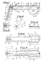
- the subject instrument comprises substantially two toothed jaws 1 and 2, integral with a pair of supporting members 3 and 4 associated with a pair of drums 5 and 6 provided with a knob 7.
- Jaws 1 and 2 are provided with teeth 8 and 9 respectively, wherein as it is clearly shown in Figure 9, openings 10 and 11 are provided, in turn having side slots 12.
- Needles 13, only one of which is shown in Figure 1 are inserted through said openings 10 and 11, and the ends of a suture thread 14 contained in a small protection tube 15 located between supporting members 3 and 4, are fastened to said needles.
- Pusher means are provided under the form of flexible wires 16 and 17 which, at one end thereof, are each fastened to drums 5 and 6, while at the opposite end they are connected to needles 13.
- jaws 1 and 2 form an angle with the supporting members 3 and 4 thereof, and this enables the instrument to be inserted through narrow areas, and a transition portion 18, shaped as an arc of a circle is provided between the jaws and the support members, so that flexible wires 16 and 17 follow an arc shaped path at said circular transition portion, while they extend straight through two thin channels 19 and 20 towards drums 5 and 6.
- Said thin channels 19 and 20, wherein flexible wires 16 and 17 are slidably mounted can be provided at the molding stage of said support members 3 and 4, or else they can be attached to the latter in the form of small tubes.
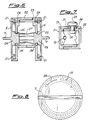
- drums 5 and 6 are provided with circumferential slots 21, preferably extending along a 270° arc, wherein wires 16 and 17 are wound.
- Said slots 21 are closed by stationary covers 22 and 23 provided with short slots 24 connected with thin channels 19 and 20 which slidably receive flexible wires 16 and 17.
- Said stationary covers 22 and 23 have a central opening 25 and hubs 26, integral with drums 5 and 6, are received through said opening and are provided with suitable coupling means 27 in order to rigidly connect said drums 5 and 6 to each other.
- the needle length must not be shorter than the length of the cavities between pairs of jaw teeth, in order to make sure that the needles enter correctly into jaw openings 10 and 11.
- overlapping support members 3 and 4 are hingedly connected to each other at 30 and they are provided with a constant width longitudinal slot 31 and with an underlying slot 32, having the same width of slot 31 at the end thereof on the side of jaws 1 and 2, while in the direction towards the support members hinge connection, said second slot 32 is gradually widening.
- a control knob 33 having a shank slidably mounted in the pair of overlapping slots 31 and 32, makes the pair of jaws to close when it is brought to the position where both slots have the same width, i.e. the position of knob 33 shown in Figure 5.
- a saw teeth retaining system just outlined in Figure 6 and shown at 34, to prevent the drums from rotating in a direction opposite to the flexible wires 16 and 17 unwinding direction from circumferential slots 21 according to arrow 28.
- the diameter of said circumferential slots is such that, when knob 7 is rotated three quarters of a turn, flexible wires 16 and 17, and therefore straight needles 13 move forward approximately 80 mm, whereby the latter can project out of ends 29 of jaws 1 and 2.
- suture thread 14 is about 0,3 mm in diameter
- slots 12 are approximately 0,4 mm wide
- flexible wires 16 and 17 are about 0,5 mm in diameter
- the diameter of the passage openings for needles 13 is about 1 mm.
- the suture thread has a diameter smaller than the width of the slots, the latter width being smaller than the flexible wire diameter, which is in turn smaller than the needle passage opening diameter, this arrangement being provided in order that suture thread 14 be able to come out of slots 12 when it is pulled by means of needles 13 passing through openings 10 and 11 of teeth 8 and 9 while being prevented to come out of slots 12.
- a modified embodiment of the subject instrument provides for a disposable central plastic material core, provided with flexible wires 16 and 17, with needles 13 and with suture thread 14. Said central core is enclosed between the pair of support members 3 and 4 which can be made out of metal in this case, provided with jaws 1 and 2 and with control drums 5 and 6, the feature being in this case that said support members are adapted for permanent use, each time with a new central core.
Abstract
Description
- This invention relates to an automatic instrument for the so called "purse-string" sutures, for surgical use, including two toothed jaws, the instrument being usable in narrow spaces and in deep spots, without requiring the needles to be manually inserted into said jaws.
- As it is known, in order to be able to take advantage of the circular mechanical suturing instruments which have been known for some time in the surgical field, it has been necessary to resort to the so called "purse-string" type sutures.
- A suture of the subject type does not involve particular difficulty and can be performed quite quickly, when operating in areas which are neither narrow nor positioned at a depth. In the above conditions said sutures may be made manually or mechanically, using the straight toothed jaw instruments, provided with openings through which one or more needles are manually slid, along one of the jaws in a first direction and subsequently along the second jaw in the opposite direction. Said instrument, which is described in British Patent No. 2 081 099, has a drawback, in that it can be used only in wide operating areas, wherein the instrument can be inserted and the straight needle can be slid through the openings provided for that purpose on the jaws.
- In order to overcome said difficulties there has been studied an instrument provided with two jaws extending along an arc, and supported by arms which are arc shaped as well. Said instrument is disclosed in European Patent No. 0119 967 and, while it is improved compared to the instrument disclosed in British Patent No. 2 081 099, still doesn't completely solve all the problems related to the purse-string suture technique: in fact, in this case as well, the needles have to be inserted manually, and the operation may prove difficult in the narrower surgical spaces.
- As it is apparent, to an extended needle length there corresponds a large surgical area required, therefore the technical problem to be solved was one of providing an automatic short needle instrument, in order to be able to use said instrument in narrow areas.
- Therefore, a main object of this invention is to find a solution to the technical problem outlined above, in order to eliminate the drawbacks of the above mentioned instruments already known, and to provide an instrument having the following advantages:
- possibility to automatically slide the needles through the openings in the jaws, i.e. without having to manually pass the needles through the openings;
- possibility to use reduced length needles, said needle length in particular being no shorter than the length of the slots between adjacent jaw teeth; and
- possibility to use straight jaws, whose manufacturing cost is lower compared to arc-shaped jaws.
- The object and the advantages mentioned above are thouroughly reached by means of the subject instrument, characterized in that support means are provided with a pair of pusher means which, at one end thereof are fastened to control means, while at the opposite end they are each connected to a respective needle, in such a way that by actuating said control means, the needles are pushed by said pusher means along the openings provided through said jaws, all the way to make said needles to project out of the free ends of said jaws.
- A further feature is the fact that a knob is integrally fastened to a pair of coaxial drums, said pusher means, comprising a pair of flexible wires being wound around said drums in the disabled position of said knob, while they unwind when said knob is operated for the purpose of pushing said flexible wires along openings in the jaws.
- Further features and advantages of this invention will become apparent from the following detailed description of a preferred although non exclusive embodiment of the subject instrument, which is also shown merely for exemplary and non limiting purposes in the attached drawing, wherein:
- Figure 1 shows a longitudinal section of the subject instrument;
- Figure 2 shows a partial view of the instrument of Figure 1, looking in the direction of arrow A;
- Figure 3 shows a partial cross section of the instrment along line III-III of Figure 1;
- Figure 4 is a view of the instrument shown in Figure 1, looking in the direction of arrow B;
- Figure 5 is a view of the instrument shown in Figure 1, looking in the direction of arrow C;
- Figure 6 is an enlarged scale cross section of the instrument, according to line VI-VI of Figure 1;
- Figure 7 is an enlarged scale cross section of the instrument, along line VII-VII of Figure 1;
- Figure 8 is a detail of the instrument of Figure 5, shown in the direction of arrow D; and
- Figure 9 is a partial cross section of both jaws along line IX-IX of Figure 1.
- Referring now to the attached drawing, the subject instrument comprises substantially two
toothed jaws 1 and 2, integral with a pair of supporting members 3 and 4 associated with a pair ofdrums Jaws 1 and 2 are provided with teeth 8 and 9 respectively, wherein as it is clearly shown in Figure 9,openings 10 and 11 are provided, in turn havingside slots 12.Needles 13, only one of which is shown in Figure 1, are inserted through saidopenings 10 and 11, and the ends of asuture thread 14 contained in asmall protection tube 15 located between supporting members 3 and 4, are fastened to said needles. - Pusher means are provided under the form of
flexible wires drums needles 13. - As it should be noted,
jaws 1 and 2 form an angle with the supporting members 3 and 4 thereof, and this enables the instrument to be inserted through narrow areas, and atransition portion 18, shaped as an arc of a circle is provided between the jaws and the support members, so thatflexible wires thin channels drums thin channels flexible wires drums circumferential slots 21, preferably extending along a 270° arc, whereinwires slots 21 are closed bystationary covers short slots 24 connected withthin channels flexible wires stationary covers central opening 25 andhubs 26, integral withdrums drums arrow 28, shown in Figure 8, whereby saidflexible wires circumferential slots 21 and they are slid alongthin channels needles 13 together withsuture thread 14 alongopenings 10 and 11 ofjaws 1 and 2, until they come out of thefree ends 29 of saidjaws 1 and 2. Since the jaws are straight, the needles as well are straight and very short compared to those known in the art, in that they are automatically pushed byflexible wires jaws 1 and 2, until they project out offree ends 29 of said jaws. However, the needle length must not be shorter than the length of the cavities between pairs of jaw teeth, in order to make sure that the needles enter correctly intojaw openings 10 and 11. As it is shown in Figures 5 and 7, to allowjaws 1 and 2 to open, overlapping support members 3 and 4 are hingedly connected to each other at 30 and they are provided with a constant widthlongitudinal slot 31 and with anunderlying slot 32, having the same width ofslot 31 at the end thereof on the side ofjaws 1 and 2, while in the direction towards the support members hinge connection, saidsecond slot 32 is gradually widening. - In that way, a
control knob 33, having a shank slidably mounted in the pair ofoverlapping slots knob 33 shown in Figure 5. - Conversely, at the position of maximum width of the variable width slot, i.e. the position of
knob 33 shown in dashed lines in Figure 1, support members 3 and 4 and therefore alsojaws 1 and 2, can be opened until the axes thereof reach positions a and b, as it is shown in Figure 5. As it is known, opening of the jaws enables the anatomical tissues to be sutured, to be pinched therebetween, and after that the jaws are closed, in this case, just by displacingcontrol knob 33 from the dashed line position to the solid line position in Figure 1. Betweendrums stationary covers flexible wires circumferential slots 21 according toarrow 28. The diameter of said circumferential slots is such that, when knob 7 is rotated three quarters of a turn,flexible wires straight needles 13 move forward approximately 80 mm, whereby the latter can project out ofends 29 ofjaws 1 and 2. - For example,
suture thread 14 is about 0,3 mm in diameter,slots 12 are approximately 0,4 mm wide,flexible wires needles 13 is about 1 mm. In other words, the suture thread has a diameter smaller than the width of the slots, the latter width being smaller than the flexible wire diameter, which is in turn smaller than the needle passage opening diameter, this arrangement being provided in order thatsuture thread 14 be able to come out ofslots 12 when it is pulled by means ofneedles 13 passing throughopenings 10 and 11 of teeth 8 and 9 while being prevented to come out ofslots 12. - A modified embodiment of the subject instrument, not shown in the drawings, provides for a disposable central plastic material core, provided with
flexible wires needles 13 and withsuture thread 14. Said central core is enclosed between the pair of support members 3 and 4 which can be made out of metal in this case, provided withjaws 1 and 2 and withcontrol drums - Practical or embodimental modifications of construction details can be made to this invention.
Claims (12)
- An automatic instrument for placing purse-string sutures for surgical use, including two jaws (1, 2) having free ends (29), each of said jaws having teeth (8, 9) each tooth being provided with an opening (10, 11) having a side slot (12) extending to an engaging surface of said tooth, each of said openings (10, 11) being adapted to receive a needle (13) passing therethrough, an end of a respective suture thread (14) being fastened to said needle (13), and jaws (1, 2) being integral with support members (3, 4) adapted to be opened in order to be able to introduce the part to be sutured between said jaws, characterized in that said support members (3, 4) are provided with a pair of pusher means (16, 17) which at one end thereof are fastened to control means (5,6,7) while at the opposite end they are each connected to a respective needle (13) in such a way that, by actuating said control means, said needles (13) are pushed by said pusher means along said openings (10, 11) provided through said jaws (1, 2), all the way to make said needles (13) to project out of said free ends (29) of said jaws (1, 2).
- The instrument of Claim 1, characterized in that a knob (7) is integrally fastened to a pair of coaxial drums (5, 6), said pusher means comprising a pair of flexible wires (16, 17) being wound around said drums in the disabled position of said knob, while they unwind when said knob (7) is operated for the purpose of pushing said flexible wires (16, 17) along openings (10, 11) of jaws (1, 2).
- The instrument of Claim 2, characterized in that both jaws (1, 2) and needles (13) are straight, the latter having a length no shorter than the length of the intermediate cavities between adjacent teeth of each jaw (1, 2).
- The instrument of Claim 2, characterized in that each drum (5, 6) is provided, for the winding of flexible wires (16, 17), with a circumferential slot (21) closed by a fixed cover (22, 23), said covers being each provided with a short slot (24), said slots (24) communicating with thin channels (19, 20) managed through said support members (3, 4), said thin channels (19, 20) slidably receiving flexible wires (16, 17) while the latter unwind out of circumferential slots (21) when knob (7) is rotated in the unwinding direction.
- The instrument of Claim 4, characterized in that said fixed covers (22, 23) of the pair of drums (5, 6) are provided with a central opening (25), and through each of said openings there is received a hub (26) integral with each drum (5, 6), and in that said hubs (26) are provided with coupling means (27) adapted to engage or disengage said drums (5, 6) relative to each other, whereby said drums may be rotated as an integral assembly by means of said knob (7), in the direction of unwinding said wires (16, 17) out of said circumferential slots (21).
- The instrument of Claim 4, characterized in that said thin channels (19, 20) wherein flexible wires (16, 17) are slidably received, may be provided in the molding stage of said supports (3, 4) or they may be applied thereto as small gauge tubes.
- The instrument of Claim 3, characterized in that each jaw (1, 2) forms an angle relative to its own support member (3, 4) through a circularly radiused transition part (18) wherein said flexible wires (16, 17) are slidably received and extend on one side towards said drums (5, 6) while on the opposite side they are connected to said needles (13) and to the ends of suture thread (14), the latter being contained in a protective small diameter tube (15).
- The instrument of Claim 1, characterized in that said support members (3, 4) are hingedly connected to each other at the end located opposite to said jaws (1, 2) and in that one of said support members is provided with a first constant width longitudinal slot (31), while the other support member is provided with a second slot overlapping the first slot, and having the same width of the latter at the end thereof located on the side of the jaws (1, 2), whereas proceeding towards the support members hinged connection, said slot (32) gradually widens whereby a control knob (33) slidably received within both slots (31, 32), when located at the position where both slots have the same width, causes the pair of jaws (1, 2) to close, whereas at the position of larger width of said slot, the pair of support members (3, 4) and therefore jaws (1, 2) can open in order to enable the part to be sutured to be introduced therebetween.
- The instrument of Claim 2, characterized in that there is provided a disposable plastic material central core containing said flexible wires (16, 17), said needles (13) and said suture thread (14), said core being inserted between said pair of hingedly connected support members (3, 4), preferably made of metal, provided with jaws (1, 2) and with said coaxial drums (5, 6) said support members (3, 4) being adapted to be durably used, each time with a new central core.
- The instrument of Claim 2, characterized in that the diameter of said suture thread (14) is smaller than the width of said slots (12) and the latter width is smaller than the diameter of flexible wires (16, 17), and in that said diameter is smaller than the diameter of openings (10, 11) receiving needles (13) therethrough.
- The instrument of Claim 4, characterized in that the diameter of circumferential slots (21) of drums (5, 6) is such that,to a three quarter of a turn rotation of knob (7) there corresponds such a forward motion of flexible wires (16, 17) to make needles (13) to project out of free end (29) of said jaws (1, 2).
- The instrument of Claim 4, characterized in that between said drums (5, 6) and stationary covers (22, 23) there is provided means (34) adapted to prevent rotation of drums (5, 6) in a direction opposite to the unwinding direction of flexible wires (16, 17) relative to circumferential slots (21).
Priority Applications (1)
| Application Number | Priority Date | Filing Date | Title |
|---|---|---|---|
| AT89830106T ATE89989T1 (en) | 1988-03-09 | 1989-03-08 | AUTOMATIC DEVICE FOR SUTURES WITH ''BAG-STRIP'' STRUCTURE FOR SURGICAL PURPOSES. |
Applications Claiming Priority (2)
| Application Number | Priority Date | Filing Date | Title |
|---|---|---|---|
| IT8819712A IT1216042B (en) | 1988-03-09 | 1988-03-09 | AUTOMATIC TOOL FOR TOBACCO BAG SUTURES FOR SURGICAL USE. |
| IT1971288 | 1988-03-09 |
Publications (2)
| Publication Number | Publication Date |
|---|---|
| EP0332591A1 EP0332591A1 (en) | 1989-09-13 |
| EP0332591B1 true EP0332591B1 (en) | 1993-06-02 |
Family
ID=11160591
Family Applications (1)
| Application Number | Title | Priority Date | Filing Date |
|---|---|---|---|
| EP89830106A Expired - Lifetime EP0332591B1 (en) | 1988-03-09 | 1989-03-08 | Automatic instrument for pursestring sutures for surgical use |
Country Status (8)
| Country | Link |
|---|---|
| US (1) | US4915107A (en) |
| EP (1) | EP0332591B1 (en) |
| JP (1) | JP2657089B2 (en) |
| AT (1) | ATE89989T1 (en) |
| CA (1) | CA1313606C (en) |
| DE (1) | DE68906811T2 (en) |
| ES (1) | ES2041444T3 (en) |
| IT (1) | IT1216042B (en) |
Families Citing this family (93)
| Publication number | Priority date | Publication date | Assignee | Title |
|---|---|---|---|---|
| US5202272A (en) * | 1991-03-25 | 1993-04-13 | International Business Machines Corporation | Field effect transistor formed with deep-submicron gate |
| US5411481A (en) * | 1992-04-08 | 1995-05-02 | American Cyanamid Co. | Surgical purse string suturing instrument and method |
| US5188636A (en) * | 1992-05-07 | 1993-02-23 | Ethicon, Inc. | Purse string suture instrument |
| US5242457A (en) * | 1992-05-08 | 1993-09-07 | Ethicon, Inc. | Surgical instrument and staples for applying purse string sutures |
| US5484451A (en) * | 1992-05-08 | 1996-01-16 | Ethicon, Inc. | Endoscopic surgical instrument and staples for applying purse string sutures |
| IT1255538B (en) * | 1992-10-08 | 1995-11-09 | TOBACCO BAG SUTURE INSTRUMENT | |
| EP0604789A1 (en) * | 1992-12-31 | 1994-07-06 | K. Widmann Ag | Surgical clamping element for making a purse string |
| US6346074B1 (en) | 1993-02-22 | 2002-02-12 | Heartport, Inc. | Devices for less invasive intracardiac interventions |
| US5797960A (en) * | 1993-02-22 | 1998-08-25 | Stevens; John H. | Method and apparatus for thoracoscopic intracardiac procedures |
| US6149660A (en) * | 1996-04-22 | 2000-11-21 | Vnus Medical Technologies, Inc. | Method and apparatus for delivery of an appliance in a vessel |
| US5891159A (en) * | 1997-05-02 | 1999-04-06 | Cardiothoratic Systems, Inc. | Automatic purse string suture device |
| US6015416A (en) * | 1998-02-26 | 2000-01-18 | Ethicon Endo-Surgery, Inc. | Surgical anastomosis instrument |
| US6036700A (en) * | 1998-07-14 | 2000-03-14 | Ethicon Endo-Surgery, Inc. | Surgical anastomosis instrument |
| US6786913B1 (en) | 1999-02-01 | 2004-09-07 | Onux Medical, Inc. | Surgical suturing instrument and method of use |
| US6332889B1 (en) | 1998-08-27 | 2001-12-25 | Onux Medical, Inc. | Surgical suturing instrument and method of use |
| US6511489B2 (en) * | 1999-08-03 | 2003-01-28 | Frederic P. Field | Surgical suturing instrument and method of use |
| US6527785B2 (en) | 1999-08-03 | 2003-03-04 | Onux Medical, Inc. | Surgical suturing instrument and method of use |
| US6679895B1 (en) * | 1999-11-05 | 2004-01-20 | Onux Medical, Inc. | Apparatus and method for placing suture wires into tissue for the approximation and tensioning of tissue |
| US6663643B2 (en) | 2000-03-27 | 2003-12-16 | Onux Medical, Inc. | Surgical suturing instrument and method of use |
| US6514263B1 (en) | 2000-08-30 | 2003-02-04 | Ethicon Endo-Surgery, Inc. | Helical needle and suture combination having a strain relief element |
| US6530932B1 (en) | 2000-08-30 | 2003-03-11 | Ethicon Endo-Surgery, Inc. | Anastomosis device having improved tissue presentation |
| US6520973B1 (en) | 2000-08-30 | 2003-02-18 | Ethicon Endo-Surgery, Inc. | Anastomosis device having an improved needle driver |
| US6613058B1 (en) | 2000-08-30 | 2003-09-02 | Ethicon Endo-Surgery, Inc. | Anastomosis device having needle receiver for capturing the needle |
| WO2002034122A2 (en) | 2000-10-20 | 2002-05-02 | Onux Medical, Inc. | Surgical suturing instrument and method of use |
| JP4139221B2 (en) * | 2000-10-20 | 2008-08-27 | ディーヴイエル アクイジション エスユービー,インク | Surgical suture instrument and method of use thereof |
| US7131980B1 (en) | 2001-01-18 | 2006-11-07 | Dvl Acquisitions Sub, Inc. | Surgical suturing instrument and method of use |
| JP2002338688A (en) * | 2001-05-15 | 2002-11-27 | Sumitomo Chem Co Ltd | Method for producing purified polyethersulfone |
| US7011668B2 (en) * | 2001-07-23 | 2006-03-14 | Dvl Acquistion Sub, Inc. | Surgical suturing instrument and method of use |
| AU2002326917A1 (en) * | 2001-09-14 | 2003-04-01 | Onux Medical, Inc. | Surgical suturing instrument and method of use |
| EP1467661A4 (en) | 2001-12-19 | 2008-11-05 | Nmt Medical Inc | Septal occluder and associated methods |
| US7318833B2 (en) * | 2001-12-19 | 2008-01-15 | Nmt Medical, Inc. | PFO closure device with flexible thrombogenic joint and improved dislodgement resistance |
| US7220265B2 (en) * | 2002-01-14 | 2007-05-22 | Nmt Medical, Inc. | Patent foramen ovale (PFO) closure method and device |
| WO2003082076A2 (en) * | 2002-03-25 | 2003-10-09 | Nmt Medical, Inc. | Patent foramen ovale (pfo) closure clips |
| CA2479974A1 (en) * | 2002-03-25 | 2003-10-09 | Dvl Acquisition Sub, Inc. | Surgical suturing instrument and method of use |
| WO2003096909A1 (en) * | 2002-05-17 | 2003-11-27 | Onux Medical, Inc. | Surgical suturing instrument and method of use |
| WO2003096885A2 (en) * | 2002-05-17 | 2003-11-27 | Onux Medical, Inc. | Surgical suturing instrument and method of use |
| US6984237B2 (en) | 2002-05-22 | 2006-01-10 | Orthopaedic Biosystems Ltd., Inc. | Suture passing surgical instrument |
| AU2003253620A1 (en) | 2002-06-03 | 2003-12-19 | Nmt Medical, Inc. | Device with biological tissue scaffold for intracardiac defect closure |
| JP2005528181A (en) | 2002-06-05 | 2005-09-22 | エヌエムティー メディカル インコーポレイテッド | Patent foramen ovale (PFO) occlusion device with radial and circumferential supports |
| US20040092973A1 (en) * | 2002-09-23 | 2004-05-13 | Nmt Medical, Inc. | Septal puncture device |
| WO2004037333A1 (en) | 2002-10-25 | 2004-05-06 | Nmt Medical, Inc. | Expandable sheath tubing |
| CA2503349A1 (en) * | 2002-11-06 | 2004-05-27 | Nmt Medical, Inc. | Medical devices utilizing modified shape memory alloy |
| AU2003287689A1 (en) * | 2002-11-07 | 2004-06-03 | Nmt Medical, Inc. | Patent foramen ovale (pfo) closure with magnetic force |
| CA2503666A1 (en) * | 2002-12-09 | 2004-06-24 | Nmt Medical, Inc. | Septal closure devices |
| US7658747B2 (en) * | 2003-03-12 | 2010-02-09 | Nmt Medical, Inc. | Medical device for manipulation of a medical implant |
| US8480706B2 (en) | 2003-07-14 | 2013-07-09 | W.L. Gore & Associates, Inc. | Tubular patent foramen ovale (PFO) closure device with catch system |
| US9861346B2 (en) | 2003-07-14 | 2018-01-09 | W. L. Gore & Associates, Inc. | Patent foramen ovale (PFO) closure device with linearly elongating petals |
| EP1651116B1 (en) * | 2003-07-14 | 2013-06-26 | W.L. Gore & Associates, Inc. | Tubular patent foramen ovale (pfo) closure device with catch system |
| WO2005018728A2 (en) * | 2003-08-19 | 2005-03-03 | Nmt Medical, Inc. | Expandable sheath tubing |
| US7691112B2 (en) * | 2003-09-11 | 2010-04-06 | Nmt Medical, Inc. | Devices, systems, and methods for suturing tissue |
| US7419498B2 (en) * | 2003-10-21 | 2008-09-02 | Nmt Medical, Inc. | Quick release knot attachment system |
| US7666203B2 (en) * | 2003-11-06 | 2010-02-23 | Nmt Medical, Inc. | Transseptal puncture apparatus |
| US8292910B2 (en) | 2003-11-06 | 2012-10-23 | Pressure Products Medical Supplies, Inc. | Transseptal puncture apparatus |
| WO2005055834A1 (en) * | 2003-11-20 | 2005-06-23 | Nmt Medical, Inc. | Device, with electrospun fabric, for a percutaneous transluminal procedure, and methods thereof |
| US20050273119A1 (en) | 2003-12-09 | 2005-12-08 | Nmt Medical, Inc. | Double spiral patent foramen ovale closure clamp |
| US8262694B2 (en) * | 2004-01-30 | 2012-09-11 | W.L. Gore & Associates, Inc. | Devices, systems, and methods for closure of cardiac openings |
| US7871419B2 (en) * | 2004-03-03 | 2011-01-18 | Nmt Medical, Inc. | Delivery/recovery system for septal occluder |
| US20050234509A1 (en) * | 2004-03-30 | 2005-10-20 | Mmt Medical, Inc. | Center joints for PFO occluders |
| US20050267524A1 (en) * | 2004-04-09 | 2005-12-01 | Nmt Medical, Inc. | Split ends closure device |
| US8361110B2 (en) * | 2004-04-26 | 2013-01-29 | W.L. Gore & Associates, Inc. | Heart-shaped PFO closure device |
| US7842053B2 (en) * | 2004-05-06 | 2010-11-30 | Nmt Medical, Inc. | Double coil occluder |
| US8308760B2 (en) * | 2004-05-06 | 2012-11-13 | W.L. Gore & Associates, Inc. | Delivery systems and methods for PFO closure device with two anchors |
| US7704268B2 (en) * | 2004-05-07 | 2010-04-27 | Nmt Medical, Inc. | Closure device with hinges |
| US8257389B2 (en) * | 2004-05-07 | 2012-09-04 | W.L. Gore & Associates, Inc. | Catching mechanisms for tubular septal occluder |
| EP1827247B8 (en) * | 2004-09-24 | 2020-05-06 | W.L. Gore & Associates, Inc. | Occluder device double securement system for delivery/recovery of such occluder device |
| US8277480B2 (en) | 2005-03-18 | 2012-10-02 | W.L. Gore & Associates, Inc. | Catch member for PFO occluder |
| WO2007120186A2 (en) * | 2005-10-24 | 2007-10-25 | Nmt Medical, Inc. | Radiopaque bioabsorbable occluder |
| EP1962695A1 (en) * | 2005-12-22 | 2008-09-03 | NMT Medical, Inc. | Catch members for occluder devices |
| CA2647505C (en) * | 2006-03-31 | 2014-07-29 | Nmt Medical, Inc. | Deformable flap catch mechanism for occluder device |
| US8870913B2 (en) | 2006-03-31 | 2014-10-28 | W.L. Gore & Associates, Inc. | Catch system with locking cap for patent foramen ovale (PFO) occluder |
| US8551135B2 (en) * | 2006-03-31 | 2013-10-08 | W.L. Gore & Associates, Inc. | Screw catch mechanism for PFO occluder and method of use |
| US20080082083A1 (en) * | 2006-09-28 | 2008-04-03 | Forde Sean T | Perforated expandable implant recovery sheath |
| WO2008077254A1 (en) * | 2006-12-26 | 2008-07-03 | Socovar Societe En Commandite | Closure apparatus |
| US7981124B2 (en) * | 2007-04-04 | 2011-07-19 | Misder, Llc | Medical device for applying purse string sutures |
| WO2008124603A1 (en) | 2007-04-05 | 2008-10-16 | Nmt Medical, Inc. | Septal closure device with centering mechanism |
| US9138562B2 (en) | 2007-04-18 | 2015-09-22 | W.L. Gore & Associates, Inc. | Flexible catheter system |
| WO2009000161A1 (en) * | 2007-06-27 | 2008-12-31 | Suzhou Touchstone International Medical Science Co., Ltd. | A surgical purse-string staple |
| US20130165967A1 (en) | 2008-03-07 | 2013-06-27 | W.L. Gore & Associates, Inc. | Heart occlusion devices |
| US20120029556A1 (en) | 2009-06-22 | 2012-02-02 | Masters Steven J | Sealing device and delivery system |
| US8956389B2 (en) | 2009-06-22 | 2015-02-17 | W. L. Gore & Associates, Inc. | Sealing device and delivery system |
| US8827136B2 (en) * | 2010-08-11 | 2014-09-09 | Covidien Lp | Endoscopic purse string surgical device |
| US8556916B2 (en) | 2011-02-14 | 2013-10-15 | Smith & Nephew, Inc. | Method and device for suture manipulation |
| US9770232B2 (en) | 2011-08-12 | 2017-09-26 | W. L. Gore & Associates, Inc. | Heart occlusion devices |
| US9821145B2 (en) | 2012-03-23 | 2017-11-21 | Pressure Products Medical Supplies Inc. | Transseptal puncture apparatus and method for using the same |
| US10828019B2 (en) | 2013-01-18 | 2020-11-10 | W.L. Gore & Associates, Inc. | Sealing device and delivery system |
| US10765420B2 (en) | 2014-04-24 | 2020-09-08 | Smith & Nephew, Inc. | Suture passer |
| US9808230B2 (en) | 2014-06-06 | 2017-11-07 | W. L. Gore & Associates, Inc. | Sealing device and delivery system |
| US9936943B1 (en) | 2014-08-07 | 2018-04-10 | Nicholas MANCINI | Suture passing surgical device with atraumatic grasper preventing accidental perforations |
| WO2017089220A1 (en) * | 2015-11-27 | 2017-06-01 | Haldor Topsøe A/S | Method of preparation of a monolithic catalyst for selective catalytic reduction of nitrogen oxides |
| WO2018081374A1 (en) | 2016-10-31 | 2018-05-03 | Smith & Nephew, Inc. | Suture passer and grasper instrument and method |
| US11219457B2 (en) * | 2018-10-11 | 2022-01-11 | Covidien Lp | Laparoscopic purse string suture device |
| US11779342B2 (en) | 2020-02-19 | 2023-10-10 | Covidien Lp | Laparoscopic purse string suture device |
| US20220183681A1 (en) * | 2020-12-15 | 2022-06-16 | Covidien Lp | Purse string suture passer device |
Family Cites Families (10)
| Publication number | Priority date | Publication date | Assignee | Title |
|---|---|---|---|---|
| DE156440C (en) * | ||||
| US3842840A (en) * | 1973-05-07 | 1974-10-22 | E Schweizer | Suture applicator |
| US4164225A (en) * | 1977-12-28 | 1979-08-14 | Johnson & Lorenz, Inc. | Surgical suturing instrument |
| US4236470A (en) * | 1979-01-17 | 1980-12-02 | Stenson Thomas K | Portable stitching device |
| US4345600A (en) * | 1980-08-04 | 1982-08-24 | Senco Products, Inc. | Purse-stringer |
| US4724840A (en) * | 1982-02-03 | 1988-02-16 | Ethicon, Inc. | Surgical fastener applier with rotatable front housing and laterally extending curved needle for guiding a flexible pusher |
| US4471781A (en) * | 1982-02-03 | 1984-09-18 | Ethicon, Inc. | Surgical instrument with rotatable front housing and latch mechanism |
| US4553544A (en) * | 1982-09-20 | 1985-11-19 | Janome Sewing Machine Co. Ltd. | Suturing instrument for surgical operation |
| IT1194556B (en) * | 1983-03-11 | 1988-09-22 | Carlo Rebuffat | CURVED BRANCH ENTER SWITCH FOR THE AUTOMATIC EXECUTION OF TOBACCO BAG SUTURES ON CABLE VISCERS |
| US4621640A (en) * | 1984-01-09 | 1986-11-11 | Mulhollan James S | Mechanical needle carrier and method for its use |
-
1988
- 1988-03-09 IT IT8819712A patent/IT1216042B/en active
-
1989
- 1989-02-27 US US07/316,299 patent/US4915107A/en not_active Expired - Fee Related
- 1989-03-06 CA CA000592837A patent/CA1313606C/en not_active Expired - Fee Related
- 1989-03-08 EP EP89830106A patent/EP0332591B1/en not_active Expired - Lifetime
- 1989-03-08 ES ES198989830106T patent/ES2041444T3/en not_active Expired - Lifetime
- 1989-03-08 DE DE8989830106T patent/DE68906811T2/en not_active Expired - Lifetime
- 1989-03-08 AT AT89830106T patent/ATE89989T1/en active
- 1989-03-09 JP JP1057654A patent/JP2657089B2/en not_active Expired - Lifetime
Also Published As
| Publication number | Publication date |
|---|---|
| DE68906811T2 (en) | 1993-09-23 |
| ATE89989T1 (en) | 1993-06-15 |
| JP2657089B2 (en) | 1997-09-24 |
| US4915107A (en) | 1990-04-10 |
| IT8819712A0 (en) | 1988-03-09 |
| EP0332591A1 (en) | 1989-09-13 |
| ES2041444T3 (en) | 1993-11-16 |
| DE68906811D1 (en) | 1993-07-08 |
| IT1216042B (en) | 1990-02-22 |
| JPH027949A (en) | 1990-01-11 |
| CA1313606C (en) | 1993-02-16 |
Similar Documents
| Publication | Publication Date | Title |
|---|---|---|
| EP0332591B1 (en) | Automatic instrument for pursestring sutures for surgical use | |
| JP2873366B2 (en) | Forceps | |
| US4633870A (en) | Apparatus for effecting anastomosis of tubular tissue by laser welding | |
| US4788978A (en) | Surgical instrument for applying linear staple sutures and intersecting the tissue therebetween | |
| AU742319B2 (en) | Surgical anastomosis instrument | |
| EP1300116B1 (en) | Surgical suturing apparatus | |
| US7122039B2 (en) | Tying knots | |
| US6117148A (en) | Intraluminal anastomotic device | |
| US7833235B2 (en) | Placing sutures | |
| JP3687683B2 (en) | Medical instruments | |
| US5733293A (en) | Disposable loading unit for a vascular suturing instrument | |
| EP0634141A1 (en) | Instrument for closing trocar puncture wounds | |
| WO1991002490A1 (en) | Surgical suture instrument with remotely controllable suture material advancement | |
| EP0592378B1 (en) | An instrument for performing purse-string sutures | |
| US5628758A (en) | Medical instrument for directed placement of a knot | |
| WO2020157753A1 (en) | Anastomosis device | |
| JP3715999B2 (en) | Suture device | |
| JP3781450B2 (en) | Suture / ligator | |
| CA2537139C (en) | Vascular suturing apparatus | |
| CA2507239C (en) | Endoscopic vascular suturing apparatus | |
| JPH08154941A (en) | Knot forming instrument | |
| JPH0889508A (en) | Suture needle | |
| AU6551599A (en) | Apparatus and method for performing colon/rectal surgery | |
| AU6551699A (en) | Apparatus and method for performing colon/rectal surgery |
Legal Events
| Date | Code | Title | Description |
|---|---|---|---|
| PUAI | Public reference made under article 153(3) epc to a published international application that has entered the european phase |
Free format text: ORIGINAL CODE: 0009012 |
|
| AK | Designated contracting states |
Kind code of ref document: A1 Designated state(s): AT BE CH DE ES FR GB GR LI LU NL SE |
|
| 17P | Request for examination filed |
Effective date: 19900131 |
|
| 17Q | First examination report despatched |
Effective date: 19920429 |
|
| GRAA | (expected) grant |
Free format text: ORIGINAL CODE: 0009210 |
|
| AK | Designated contracting states |
Kind code of ref document: B1 Designated state(s): AT BE CH DE ES FR GB GR LI LU NL SE |
|
| PG25 | Lapsed in a contracting state [announced via postgrant information from national office to epo] |
Ref country code: GR Free format text: LAPSE BECAUSE OF FAILURE TO SUBMIT A TRANSLATION OF THE DESCRIPTION OR TO PAY THE FEE WITHIN THE PRESCRIBED TIME-LIMIT Effective date: 19930602 |
|
| REF | Corresponds to: |
Ref document number: 89989 Country of ref document: AT Date of ref document: 19930615 Kind code of ref document: T |
|
| REF | Corresponds to: |
Ref document number: 68906811 Country of ref document: DE Date of ref document: 19930708 |
|
| ET | Fr: translation filed | ||
| REG | Reference to a national code |
Ref country code: ES Ref legal event code: FG2A Ref document number: 2041444 Country of ref document: ES Kind code of ref document: T3 |
|
| PLBE | No opposition filed within time limit |
Free format text: ORIGINAL CODE: 0009261 |
|
| STAA | Information on the status of an ep patent application or granted ep patent |
Free format text: STATUS: NO OPPOSITION FILED WITHIN TIME LIMIT |
|
| 26N | No opposition filed | ||
| EAL | Se: european patent in force in sweden |
Ref document number: 89830106.4 |
|
| PGFP | Annual fee paid to national office [announced via postgrant information from national office to epo] |
Ref country code: LU Payment date: 19950301 Year of fee payment: 7 |
|
| PGFP | Annual fee paid to national office [announced via postgrant information from national office to epo] |
Ref country code: GB Payment date: 19950321 Year of fee payment: 7 |
|
| PGFP | Annual fee paid to national office [announced via postgrant information from national office to epo] |
Ref country code: ES Payment date: 19950322 Year of fee payment: 7 Ref country code: CH Payment date: 19950322 Year of fee payment: 7 |
|
| PGFP | Annual fee paid to national office [announced via postgrant information from national office to epo] |
Ref country code: SE Payment date: 19950327 Year of fee payment: 7 |
|
| PGFP | Annual fee paid to national office [announced via postgrant information from national office to epo] |
Ref country code: AT Payment date: 19950329 Year of fee payment: 7 |
|
| PGFP | Annual fee paid to national office [announced via postgrant information from national office to epo] |
Ref country code: FR Payment date: 19950330 Year of fee payment: 7 Ref country code: DE Payment date: 19950330 Year of fee payment: 7 |
|
| PGFP | Annual fee paid to national office [announced via postgrant information from national office to epo] |
Ref country code: NL Payment date: 19950331 Year of fee payment: 7 |
|
| PGFP | Annual fee paid to national office [announced via postgrant information from national office to epo] |
Ref country code: BE Payment date: 19950412 Year of fee payment: 7 |
|
| PG25 | Lapsed in a contracting state [announced via postgrant information from national office to epo] |
Ref country code: LU Free format text: LAPSE BECAUSE OF NON-PAYMENT OF DUE FEES Effective date: 19960308 Ref country code: GB Effective date: 19960308 Ref country code: AT Effective date: 19960308 |
|
| PG25 | Lapsed in a contracting state [announced via postgrant information from national office to epo] |
Ref country code: SE Effective date: 19960309 Ref country code: ES Free format text: LAPSE BECAUSE OF NON-PAYMENT OF DUE FEES Effective date: 19960309 |
|
| PG25 | Lapsed in a contracting state [announced via postgrant information from national office to epo] |
Ref country code: LI Effective date: 19960331 Ref country code: CH Effective date: 19960331 Ref country code: BE Effective date: 19960331 |
|
| BERE | Be: lapsed |
Owner name: HARLEY INTERNATIONAL MEDICAL LTD Effective date: 19960331 |
|
| PG25 | Lapsed in a contracting state [announced via postgrant information from national office to epo] |
Ref country code: NL Effective date: 19961001 |
|
| GBPC | Gb: european patent ceased through non-payment of renewal fee |
Effective date: 19960308 |
|
| REG | Reference to a national code |
Ref country code: CH Ref legal event code: PL |
|
| PG25 | Lapsed in a contracting state [announced via postgrant information from national office to epo] |
Ref country code: FR Effective date: 19961129 |
|
| NLV4 | Nl: lapsed or anulled due to non-payment of the annual fee |
Effective date: 19961001 |
|
| PG25 | Lapsed in a contracting state [announced via postgrant information from national office to epo] |
Ref country code: DE Effective date: 19961203 |
|
| EUG | Se: european patent has lapsed |
Ref document number: 89830106.4 |
|
| REG | Reference to a national code |
Ref country code: FR Ref legal event code: ST |
|
| REG | Reference to a national code |
Ref country code: ES Ref legal event code: FD2A Effective date: 19990503 |