EP0331257A2 - Universal remote control transmitter with simplified device indentification - Google Patents
Universal remote control transmitter with simplified device indentification Download PDFInfo
- Publication number
- EP0331257A2 EP0331257A2 EP89200476A EP89200476A EP0331257A2 EP 0331257 A2 EP0331257 A2 EP 0331257A2 EP 89200476 A EP89200476 A EP 89200476A EP 89200476 A EP89200476 A EP 89200476A EP 0331257 A2 EP0331257 A2 EP 0331257A2
- Authority
- EP
- European Patent Office
- Prior art keywords
- remote control
- memory
- keyboard
- devices
- key
- Prior art date
- Legal status (The legal status is an assumption and is not a legal conclusion. Google has not performed a legal analysis and makes no representation as to the accuracy of the status listed.)
- Granted
Links
Images

Classifications
-
- H—ELECTRICITY
- H04—ELECTRIC COMMUNICATION TECHNIQUE
- H04Q—SELECTING
- H04Q9/00—Arrangements in telecontrol or telemetry systems for selectively calling a substation from a main station, in which substation desired apparatus is selected for applying a control signal thereto or for obtaining measured values therefrom
-
- H—ELECTRICITY
- H04—ELECTRIC COMMUNICATION TECHNIQUE
- H04B—TRANSMISSION
- H04B1/00—Details of transmission systems, not covered by a single one of groups H04B3/00 - H04B13/00; Details of transmission systems not characterised by the medium used for transmission
- H04B1/06—Receivers
- H04B1/16—Circuits
- H04B1/20—Circuits for coupling gramophone pick-up, recorder output, or microphone to receiver
- H04B1/202—Circuits for coupling gramophone pick-up, recorder output, or microphone to receiver by remote control
-
- G—PHYSICS
- G08—SIGNALLING
- G08C—TRANSMISSION SYSTEMS FOR MEASURED VALUES, CONTROL OR SIMILAR SIGNALS
- G08C19/00—Electric signal transmission systems
- G08C19/16—Electric signal transmission systems in which transmission is by pulses
- G08C19/28—Electric signal transmission systems in which transmission is by pulses using pulse code
-
- G—PHYSICS
- G08—SIGNALLING
- G08C—TRANSMISSION SYSTEMS FOR MEASURED VALUES, CONTROL OR SIMILAR SIGNALS
- G08C2201/00—Transmission systems of control signals via wireless link
- G08C2201/90—Additional features
- G08C2201/92—Universal remote control
Definitions
- the present invention relates to remote control transmitters and, particularly, to remote control transmitters for controlling home appliances of different manufacturers and categories to carry out selected operations.
- a television set can be turned on and off, a channel can be selected, a video cassette recorder controlled to play or record, etc.
- each manufacturer effects this control differently.
- the bit pattern required to carry out a given operation differs for different manufacturers.
- the basic format such as the bit timing, the number of bits per word, the width of the pulses, the modulating frequency, if any, applied to each pulse, the presence of, length of, and format of start, lead, or trailer pulses and the number of correct receptions of a particular command required to activate the appliance to carry out the selected operation varies from manufacturer to manufacturer.
- the basic format may also be different for different model numbers of the same manufacturer.
- control of, for example, a video cassette recorder frequently requires the ability to control a related appliance, e.g. a television set, in conjunction therewith.
- a related appliance e.g. a television set
- viewing a recorded program requires use of two individual remote control units, particularly if the recorder and the television set are not made by the same manufacturer. If the home is equipped with cable television, or if other appliances such as, for example, an oven can be remotely controlled, the number of required remote control transmitters becomes excessive.
- the present invention is a direct entry system for remote control transmitters. Specifically, it is used in conjunction with remote control transmitters which transmit signals remotely controlling a selected one of a plurality of devices of different categories manufacture by different manufacturers. Each device requires a different signal format, all of the signal formats for the different categories and manufacturers being permanently stored in a memory at respective memory addresses.
- the user first activates an entry initiate key. Thereafter the user selects one of a plurality of keys, each signifying a particular category. Finally, the user activates at least one key (two keys in a preferred embodiment), to signify the address in the memory storing the specific device formatting data. This data is read out and applied to a microprocessor which, in turn, controls the sending of correctly formatted signals to the transmitter driver circuit.
- the transmitters are infrared light emitting diodes.
- microprocessor 10 which is the central control unit for the system, is denoted by reference numeral 10.
- the timing of microprocessor 10 is controlled by a crystal time base 12.
- microprocessor 10 first receives data from two or even only one user-controlled selector device described in detail below.
- the selector device is utilized by a "decode" program located in an internal ROM 14 of microprocessor 10 to calculate an address for an electrically programmable read only memory (EPROM) 16 separate from microprocessor 10.
- EPROM electrically programmable read only memory
- the memory could equally well be an EEPROM or a ROM and internal rather than external to microprocessor 10.
- the generated address is then put out on a two-way, eight line bus 18 and an address latch 20 is enabled.
- the address is stored in latch 20 and, subsequently, as timed by microprocessor 10, the address from latch 20 is applied to an eight line bus 22, and combined with the signal on three lines 24 emanating from microprocessor 10.
- the combined address is applied to an address decoder 26 as well as EPROM 16.
- Address decoder 26 first enables a "select” line and, thereafter, an "output enable” line for EPROM 16, again under microprocessor control.
- Data from EPROM 16 is transmitted through an eight line bus 28 and bus 18 back to microprocessor 10.
- the data from EPROM 16 is then used within microprocessor 10 to energize an infrared transmission drive circuit 29 so that infrared light emitting diodes 30 transmit signals with a corresponding signal structure, i.e. bit pattern and signal format.
- the transmitted infrared radiation is received by the appliance and causes it to operate as desired by the user.
- the word "format” as used herein refers to parameters such as pulse width, frequency, number of bits per word, modulating frequency, if any, applied to each pulse, the presence of, length of, and shape of start, lead or trailer pulses and the number of correct receptions of a particular command required to activate the appliance to carry out the selected operation.
- Other parameters can be added if required, and nonrelevant parameters can be omitted depending upon the particular appliances to be controlled.
- the microprocessor is a Hitachi HD6301 operated in mode 6 with an oscillator frequency of 4MHz and an instruction cycle time of 1 microsecond. This speed is necessary in order to generate the carrier output frequencies of up to 55 KHz required by some IR control systems.
- Tne first of the user-operated selector devices is a category selector switch 32, by which the user selects the category of the appliance which is to be controlled. Its output is connected to microprocessor 10 through five lines 34, the selected line being grounded. A set of category bits signifying the user-selected category is stored in a random access memory (RAM) 44 in microprocessor 10.
- RAM random access memory
- the following categories are provided: a television receiver (TV), a video cassette recorder (VCR), a disc player (disc), an audio system (audio), and an auxiliary input (aux) suitable, for example, for controlling a cable converter.
- This selector switch is present for functions outside of the present invention. It can be omitted with respect to the direct keyboard entry method and system according to this invention.
- the second selector device is used for direct entry of data signifying the manufacturer and model number of the device to be controlled.
- This function is in addition to the other functions carried out by means of keyboard 36 in the parent application and in U.S. 4,703,359, a continuation-in-part of the same parent.
- Fig. 1 hereof is identical to Fig. 1 of U.S. Patent 4,703,359, both the patent and the present application being improvements on the apparatus illustrated in the parent application.
- switches 30a and 30b of Fig. 1 of the parent application are omitted in both continuations-in-part.
- the switches are replaced by an operation in which a command is transmitted in different formats until the controlled device executes the commanded operation.
- direct entry through the keyboard of data permitting the correct address for the tables in EPROM 16 to be formed is provided instead.
- Keyboard 36 is a 3x11 matrix, addressable by 11 address lines of a bus 38.
- Bus 38 is constituted by eight line bus 22 and three line bus 24.
- address decoder 26 enables a buffer 40, and each of the eleven columns is energized in turn by microprocessor 10 via bus 38.
- An output is obtained on the one of the three output lines 42 connected to an energized column by a user-depressed key. This output is then transmitted through buffer 40 and bus 18 to microprocessor 10. There, the result of the keyboard scan is stored in RAM 44.
- keyboard 36 has individual power keys marked "CBL”, "VCR”, and "TV”, etc., respectively marked 36a, 36b and 36c in Fig. 1. It further has a record key, as well as keys numbered from one to nine and 0, channel up and down keys, etc.
- the user procedure for direct keyboard entry is first to press the "entry initiate” button, then to press one of the power buttons described above in order to select the category, and then to enter two digits which together signify the manufacturer and model number.
- This information is available, for example, in an instruction book.
- This keyboard-entry data is also stored in RAM 44. As illustrated in Fig. 1, RAM 44 is internal to microprocessor 10. An external memory could be used equally well.
- EPROM 16 contains command look-up tables which, according to the present invention, can be indexed or addressed by data in RAM 44 derived solely from entries on keyboard 18. Alternatively, keyboard entry data without the power button activation may be combined with category selector switch data to provide the necessary pointers for addressing items in the look-up tables in EPROM 16.
- the data read out from the specific device tables, is passed to a formatter, also stored in EPROM 16.
- Each formatter has a device-specific program designed to generate the precise carrier frequency, pulse width, pulse modulation and overall timing format required by the particular device to be controlled.
- the data output lines from keyboard 36 are also connected to the inputs of a stand-by circuit 46.
- a first and second output of stand-by circuit 46 is connected to a reset and stand-by input of microprocessor 10, respectively.
- Standby circuit 46 was illustrated in greater detail in copending U.S. Application Serial No. 739,357. Its description will not be repeated here since it is not essential for an understanding of the present invention.
- microprocessor 10 is connected to IR drive circuit 29 which in turn drives infrared light emitting diodes (LED's) 30.
- LED's infrared light emitting diodes
- microprocessor initialization takes place.
- RAM 44, the input-output ports, and a flag in the internal memory of the microprocessor are set to initial conditions.
- Data in RAM 44 is set to address the first entry in the tables in EPROM 16.
- the microprocessor then enters the sleep mode. In this mode, stand-by circuit 46 grounds the reset and stand-by pins of the microprocessor.
- a circuit internal to the microprocessor shuts down all internal circuitry except for memory and the circuitry monitoring the "stand-by" and "reset” lines. This state continues until a key of keyboard 36 is pressed.
- microprocessor 10 Upon pressing of a key, the "reset" and “stand-by” circuits in microprocessor 10 are energized. Monitoring of the stand-by and reset lines as well as the previously set flag causes the microprocessor to energize the latch for stand-by circuit 46 and to enable address latch 20.
- the microprocessor then executes a keyboard scan program stored in ROM 14 via bus 38. If a key on keyboard 36 is pressed, one of the keyboard rows is connected to its column, causing one of the lines of bus 42 to be at a high level at a specific step in the program. This information is utilized by a program in ROM 14 to determine the position number of any pressed key.
- the microprocessor then enters the multikey patch subroutine shown in Fig. 3. It is first determined whether the number of keys pressed is equal to one or greater than one. If the number is greater than one, the routine on the right hand side of Fig. 3 is followed.
- This routine includes the "record” mode which is irrelevant to an understanding of the present invention and will therefore not be described further herein. It also allows operation of the "learn” routine described in U.S. Patent 4,703,359. This routine may be used advantageously in conjunction with the direct entry keyboard routine which is the subject of the present invention, but is not essential thereto. Specifically, the "learn" routine of U.S.
- Patent 4,703,359 can be used to select the required signal structure data from the tables in EPROM 16 or its equivalent if the model identification digits which have to be pressed by the user for the direct entry method of this invention are not available, i.e. if, for example, the manufacturer or model number is not listed in the instruction book, or the instructions have been lost. In any case, if the number of keys pressed exceeds one, the routine is not part of the present invention and will not be described in detail herein.
- the microprocessor first tests whether this is the record key. If the user has pressed the record key (herein also referred to as the enter initiate key), he has taken the initial step for implementing the present invention, i.e. for entering the necessary data for identifying a particular manufacturer and model number directly on the keyboard. Therefore if the answer is yes, the subroutine illustrated in Fig. 4 is followed.
- a time-out counter is loaded.
- the keyboard is then scanned. If the user has stopped pressing the record key but has not as yet pressed another key, the "key pressed?" test which is carried out next will yield a "no". If the time-out counter has not as yet run out, the subsequent "time-out” test will also yield a "no". This will cause a repetition of the keyboard scan. If, on the other hand, the time-out counter has run down, the microprocessor goes back to the sleep mode until further activation by the user.
- the procedure followed by the user when directly entering the manufacturer and model identification data into the transmitter is to press one of the power buttons after pressing the record button.
- the microprocessor tests which of the power buttons (three illustrated in Fig. 4) has been pressed and stores category data in RAM 44 accordingly.
- this step is replaced by positioning category selector switch 32 and entering the so-selected category data in RAM 44.
- the program continues as illustrated in Fig. 5.
- the keyboard is again scanned. A test is carried out to see whether a digit has been entered. If no digit has been entered, it is tested whether a non-digit has been entered. If the answer to this is also a no, a ten second time-out is tested. If the time-out has expired, the microprocessor again returns to its sleep state. If the ten second time-out has not as yet expired, the keyboard scan is repeated.
- the user will be entering the two digits which together identify the manufacturer and model number. If a digit has been entered, this is stored as the first digit of the two digit specific device entry pointer or address in RAM 44. Thereafter, the keyboard is again scanned. If the next digit has been entered, this digit is stored as the second digit and the transmitter again enters its sleep state. However, the specific device data required, for example, for calculating the address of a table in EPROM 16 is now stored in RAM 44. If no digit had been entered, it is again tested whether a non-digit has been entered. If so, the main program is reentered as described above with respect to a non-digit entry. If no key at all has been pressed, the time-out clock is again checked. If the clock has run out, the equipment again returns to its sleep state.
- the category switch is read again and the result stored in internal RAM 14 (see Fig. 2).
- the microprocessor executes the keyboard scan program as before, and as before, the multikey patch is entered. If the key is neither the record key nor the play key, the multikey patch (Fig. 3) is exited, and the keyboard position number is stored in the internal RAM 44. (Fig. 2)
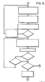
- the program then continues as illustrated in Fig. 6.
- the mode of operation illustrated in Fig. 6 is the send mode.
- the "decode" program in internal ROM 14 of microprocessor 10 uses the stored category data and stored signal structure identification data (specific device pointer) to calculate the address of a command table in EPROM 16.
- the command table stores the following data for each key position:
- the command table address calculated by the decode program is then combined with the command key data to read out the above data from EPROM 16.
- a comparison of the selected category type stored in RAM 44 and the category type found in the command table is carried out. If the two do not match, the category data in RAM is replaced with the category data found in the table.
- the program then reenters the decode program.
- This category matching step is required for use of commands in other categories from the one selected (e.g. T.V. volume up with VCR category selected). Since this process is explained in the parent case and is not required for understanding the present invention, no further explanation will be given here.
- the program jumps to the formatter starting address. Instructions are executed to send infrared code to the infrared driver.
- the formatter instructions stored in EPROM 16 cause the microprocessor to send the command word bit pattern to the IR driver in the format (carrier frequency, pulse type, timing, etc.) appropriate for the controlled appliance.
- a renewed keyboard scan is then carried out. It is determined whether the same key is still pressed. If so, it is further tested whether the repeat flag is on. If the repeat flag is on, the program returns to the formatter starting address and the transmitter repeats sending the previously sent code.
- the method and apparatus of the present invention as described above allow the user to select the manufacturer and model number of the device to be controlled simply by four keyboard entries.
- the present invention can further be combined with the method and system disclosed in U.S. Patent 4,703,359.
- a remote control transmitter embodying both concepts allows the user to enter the manufacturers' model number by means of the keyboard when the keyboard entry values are available and allows the scanning method of the '359 patent to be employed if the instruction book is lost or if the instruction book does not list the particular manufacturer. Since many firms sell other manufacturers' televisions, receivers, VCR'S, etc. under their own label, it is entirely possible that the scanning approach will show that the appliance can be controlled by the remote control transmitter even though no listing appeared in the instruction book.
Abstract
Description
- The present application is a continuation-in-part of the application entitled "Universal Remote Control Unit", Serial No. 739,357, filed May 30, 1985, and assigned to the predecessor in interest of the present assignee.
- The present invention relates to remote control transmitters and, particularly, to remote control transmitters for controlling home appliances of different manufacturers and categories to carry out selected operations.
- At present, many home appliances are available which can be remotely controlled by the user. For example, a television set can be turned on and off, a channel can be selected, a video cassette recorder controlled to play or record, etc. However, each manufacturer effects this control differently. The bit pattern required to carry out a given operation differs for different manufacturers. Similarly, the basic format, such as the bit timing, the number of bits per word, the width of the pulses, the modulating frequency, if any, applied to each pulse, the presence of, length of, and format of start, lead, or trailer pulses and the number of correct receptions of a particular command required to activate the appliance to carry out the selected operation varies from manufacturer to manufacturer. The basic format may also be different for different model numbers of the same manufacturer.
- Further, control of, for example, a video cassette recorder frequently requires the ability to control a related appliance, e.g. a television set, in conjunction therewith. At present, viewing a recorded program requires use of two individual remote control units, particularly if the recorder and the television set are not made by the same manufacturer. If the home is equipped with cable television, or if other appliances such as, for example, an oven can be remotely controlled, the number of required remote control transmitters becomes excessive.
- Althrough some universal remote control transmitters with which devices of different categories and manufactured by different manufacturers can be controlled are known, these are not entirely satisfactory. All "universal" remote control transmitters have the required formatting and bit patterns data permanently stored in memory. The data for controlling the particular device must thus be read out from this memory. In some universal remote control transmitters this requires a relatively awkward setting of switches, while a time consuming process of scanning all device control signals permanently stored in the transmitter must take place in others.
- It is an object of the present invention to furnish a remote control transmitter capable of controlling different types of appliances manufactured by different manufacturers which provides an easy and rapid method for reading out the correct bit pattern and formatting data from the memory storing such data for devices to be controlled.
- The present invention is a direct entry system for remote control transmitters. Specifically, it is used in conjunction with remote control transmitters which transmit signals remotely controlling a selected one of a plurality of devices of different categories manufacture by different manufacturers. Each device requires a different signal format, all of the signal formats for the different categories and manufacturers being permanently stored in a memory at respective memory addresses. The user first activates an entry initiate key. Thereafter the user selects one of a plurality of keys, each signifying a particular category. Finally, the user activates at least one key (two keys in a preferred embodiment), to signify the address in the memory storing the specific device formatting data. This data is read out and applied to a microprocessor which, in turn, controls the sending of correctly formatted signals to the transmitter driver circuit. Preferably, the transmitters are infrared light emitting diodes.
- Detailed operation as well the implementation of the present invention will be explained with reference to drawing.
-
- Fig. 1 is a block diagram of a remote control transmitter and associated apparatus incorporating the present invention;
- Fig. 2 is a flow chart of the main microprocessor program;
- Fig. 3 is a flow chart of the multikey program;
- Fig. 4a and 4b are, together, the flow chart for the direct entry identify program; and
- Fig. 5 is the flow chart for the transmit program.
- The present invention is disclosed herein as part of the remote control transmitter described in the copending application, Serial No. 739,357, which is herein incorporated by reference. Only the parts of the disclosure of the parent application which are required for understanding the present invention will be repeated below. While the so-described apparatus constitutes a preferred embodiment, the present invention is also useable with other types of remote control transmitters or units.
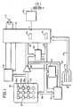
- Referring now to the drawing, in Fig. 1, a microprocessor, which is the central control unit for the system, is denoted by reference numeral 10. The timing of microprocessor 10 is controlled by a
crystal time base 12. In normal operation, microprocessor 10 first receives data from two or even only one user-controlled selector device described in detail below. The selector device is utilized by a "decode" program located in aninternal ROM 14 of microprocessor 10 to calculate an address for an electrically programmable read only memory (EPROM) 16 separate from microprocessor 10. The memory could equally well be an EEPROM or a ROM and internal rather than external to microprocessor 10. The generated address is then put out on a two-way, eightline bus 18 and anaddress latch 20 is enabled. The address is stored inlatch 20 and, subsequently, as timed by microprocessor 10, the address fromlatch 20 is applied to an eight line bus 22, and combined with the signal on threelines 24 emanating from microprocessor 10. The combined address is applied to anaddress decoder 26 as well as EPROM 16.Address decoder 26 first enables a "select" line and, thereafter, an "output enable" line for EPROM 16, again under microprocessor control. Data from EPROM 16 is transmitted through an eightline bus 28 andbus 18 back to microprocessor 10. The data from EPROM 16 is then used within microprocessor 10 to energize an infraredtransmission drive circuit 29 so that infrared light emitting diodes 30 transmit signals with a corresponding signal structure, i.e. bit pattern and signal format. The transmitted infrared radiation is received by the appliance and causes it to operate as desired by the user. - It should be noted that the word "format" as used herein refers to parameters such as pulse width, frequency, number of bits per word, modulating frequency, if any, applied to each pulse, the presence of, length of, and shape of start, lead or trailer pulses and the number of correct receptions of a particular command required to activate the appliance to carry out the selected operation. Other parameters can be added if required, and nonrelevant parameters can be omitted depending upon the particular appliances to be controlled.
- In a preferred embodiment, the microprocessor is a Hitachi HD6301 operated in mode 6 with an oscillator frequency of 4MHz and an instruction cycle time of 1 microsecond. This speed is necessary in order to generate the carrier output frequencies of up to 55 KHz required by some IR control systems.
- Tne first of the user-operated selector devices is a
category selector switch 32, by which the user selects the category of the appliance which is to be controlled. Its output is connected to microprocessor 10 through fivelines 34, the selected line being grounded. A set of category bits signifying the user-selected category is stored in a random access memory (RAM) 44 in microprocessor 10. In the example illustrated in Fig. 1, the following categories are provided: a television receiver (TV), a video cassette recorder (VCR), a disc player (disc), an audio system (audio), and an auxiliary input (aux) suitable, for example, for controlling a cable converter. This selector switch is present for functions outside of the present invention. It can be omitted with respect to the direct keyboard entry method and system according to this invention. - In accordance with the present invention, the second selector device,
keyboard 36, is used for direct entry of data signifying the manufacturer and model number of the device to be controlled. This function is in addition to the other functions carried out by means ofkeyboard 36 in the parent application and in U.S. 4,703,359, a continuation-in-part of the same parent. (It shoudl be noted that Fig. 1 hereof is identical to Fig. 1 of U.S. Patent 4,703,359, both the patent and the present application being improvements on the apparatus illustrated in the parent application. Specifically, switches 30a and 30b of Fig. 1 of the parent application are omitted in both continuations-in-part. In the '359 patent, the switches are replaced by an operation in which a command is transmitted in different formats until the controlled device executes the commanded operation. In the present invention, direct entry through the keyboard of data permitting the correct address for the tables inEPROM 16 to be formed is provided instead.) -
Keyboard 36 is a 3x11 matrix, addressable by 11 address lines of abus 38.Bus 38 is constituted by eight line bus 22 and threeline bus 24. During a keyboard scan, addressdecoder 26 enables abuffer 40, and each of the eleven columns is energized in turn by microprocessor 10 viabus 38. An output is obtained on the one of the threeoutput lines 42 connected to an energized column by a user-depressed key. This output is then transmitted throughbuffer 40 andbus 18 to microprocessor 10. There, the result of the keyboard scan is stored inRAM 44. It should be noted thatkeyboard 36 has individual power keys marked "CBL", "VCR", and "TV", etc., respectively marked 36a, 36b and 36c in Fig. 1. It further has a record key, as well as keys numbered from one to nine and 0, channel up and down keys, etc. - The user procedure for direct keyboard entry is first to press the "entry initiate" button, then to press one of the power buttons described above in order to select the category, and then to enter two digits which together signify the manufacturer and model number. This information is available, for example, in an instruction book. This keyboard-entry data is also stored in
RAM 44. As illustrated in Fig. 1,RAM 44 is internal to microprocessor 10. An external memory could be used equally well. -
EPROM 16 contains command look-up tables which, according to the present invention, can be indexed or addressed by data inRAM 44 derived solely from entries onkeyboard 18. Alternatively, keyboard entry data without the power button activation may be combined with category selector switch data to provide the necessary pointers for addressing items in the look-up tables inEPROM 16. - The data read out from the specific device tables, is passed to a formatter, also stored in
EPROM 16. Each formatter has a device-specific program designed to generate the precise carrier frequency, pulse width, pulse modulation and overall timing format required by the particular device to be controlled. - The data output lines from
keyboard 36 are also connected to the inputs of a stand-by circuit 46. A first and second output of stand-by circuit 46 is connected to a reset and stand-by input of microprocessor 10, respectively. -
Standby circuit 46 was illustrated in greater detail in copending U.S. Application Serial No. 739,357. Its description will not be repeated here since it is not essential for an understanding of the present invention. - Finally, an output port 11 of microprocessor 10 is connected to
IR drive circuit 29 which in turn drives infrared light emitting diodes (LED's) 30. - More detailed operation of the above-described equipment, with particular emphasis on the direct entry keyboard mode will now be described with reference to flow charts, Figs. 2, 3, 4 and 5.
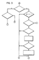
- Referring now to Fig. 2, upon insertion of the battery, microprocessor initialization takes place.
RAM 44, the input-output ports, and a flag in the internal memory of the microprocessor are set to initial conditions. Data inRAM 44 is set to address the first entry in the tables inEPROM 16. The microprocessor then enters the sleep mode. In this mode, stand-by circuit 46 grounds the reset and stand-by pins of the microprocessor. A circuit internal to the microprocessor shuts down all internal circuitry except for memory and the circuitry monitoring the "stand-by" and "reset" lines. This state continues until a key ofkeyboard 36 is pressed. - Upon pressing of a key, the "reset" and "stand-by" circuits in microprocessor 10 are energized. Monitoring of the stand-by and reset lines as well as the previously set flag causes the microprocessor to energize the latch for stand-
by circuit 46 and to enableaddress latch 20. - The microprocessor then executes a keyboard scan program stored in
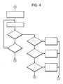
ROM 14 viabus 38. If a key onkeyboard 36 is pressed, one of the keyboard rows is connected to its column, causing one of the lines ofbus 42 to be at a high level at a specific step in the program. This information is utilized by a program inROM 14 to determine the position number of any pressed key. - The microprocessor then enters the multikey patch subroutine shown in Fig. 3. It is first determined whether the number of keys pressed is equal to one or greater than one. If the number is greater than one, the routine on the right hand side of Fig. 3 is followed. This routine includes the "record" mode which is irrelevant to an understanding of the present invention and will therefore not be described further herein. It also allows operation of the "learn" routine described in U.S. Patent 4,703,359. This routine may be used advantageously in conjunction with the direct entry keyboard routine which is the subject of the present invention, but is not essential thereto. Specifically, the "learn" routine of U.S. Patent 4,703,359 can be used to select the required signal structure data from the tables in
EPROM 16 or its equivalent if the model identification digits which have to be pressed by the user for the direct entry method of this invention are not available, i.e. if, for example, the manufacturer or model number is not listed in the instruction book, or the instructions have been lost. In any case, if the number of keys pressed exceeds one, the routine is not part of the present invention and will not be described in detail herein. - If the number of keys pressed is equal to one, the microprocessor first tests whether this is the record key. If the user has pressed the record key (herein also referred to as the enter initiate key), he has taken the initial step for implementing the present invention, i.e. for entering the necessary data for identifying a particular manufacturer and model number directly on the keyboard. Therefore if the answer is yes, the subroutine illustrated in Fig. 4 is followed.
- As illustrated in Fig. 4, if the key that has been pressed is the record key, a time-out counter is loaded. The keyboard is then scanned. If the user has stopped pressing the record key but has not as yet pressed another key, the "key pressed?" test which is carried out next will yield a "no". If the time-out counter has not as yet run out, the subsequent "time-out" test will also yield a "no". This will cause a repetition of the keyboard scan. If, on the other hand, the time-out counter has run down, the microprocessor goes back to the sleep mode until further activation by the user.
- As mentioned above, the procedure followed by the user when directly entering the manufacturer and model identification data into the transmitter is to press one of the power buttons after pressing the record button. Thus if the "key pressed" test yields an affirmative result, the microprocessor tests which of the power buttons (three illustrated in Fig. 4) has been pressed and stores category data in
RAM 44 accordingly. In an alternative embodiment, this step is replaced by positioningcategory selector switch 32 and entering the so-selected category data inRAM 44. - If on the other hand none of the three power buttons has been pressed, the main program of Fig. 3 is reentered at D.
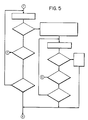
- If one of the category power switches has been pressed, and the corresponding value entered in
RAM 14, the program continues as illustrated in Fig. 5. The keyboard is again scanned. A test is carried out to see whether a digit has been entered. If no digit has been entered, it is tested whether a non-digit has been entered. If the answer to this is also a no, a ten second time-out is tested. If the time-out has expired, the microprocessor again returns to its sleep state. If the ten second time-out has not as yet expired, the keyboard scan is repeated. - At this point, again in accordance with the above-described procedure, the user will be entering the two digits which together identify the manufacturer and model number. If a digit has been entered, this is stored as the first digit of the two digit specific device entry pointer or address in
RAM 44. Thereafter, the keyboard is again scanned. If the next digit has been entered, this digit is stored as the second digit and the transmitter again enters its sleep state. However, the specific device data required, for example, for calculating the address of a table inEPROM 16 is now stored inRAM 44. If no digit had been entered, it is again tested whether a non-digit has been entered. If so, the main program is reentered as described above with respect to a non-digit entry. If no key at all has been pressed, the time-out clock is again checked. If the clock has run out, the equipment again returns to its sleep state. - After the circuit has been reactivated upon pressing of a new key (which will signify a desired command such as "channel up"), the category switch is read again and the result stored in internal RAM 14 (see Fig. 2). The microprocessor executes the keyboard scan program as before, and as before, the multikey patch is entered. If the key is neither the record key nor the play key, the multikey patch (Fig. 3) is exited, and the keyboard position number is stored in the
internal RAM 44. (Fig. 2) - The program then continues as illustrated in Fig. 6. The mode of operation illustrated in Fig. 6 is the send mode.
- In the send mode, the "decode" program in
internal ROM 14 of microprocessor 10 uses the stored category data and stored signal structure identification data (specific device pointer) to calculate the address of a command table inEPROM 16. The command table stores the following data for each key position: - 1. The command word bit pattern
- 2. The formatter starting address
- 3. A repeating/not repeating flag
- 4. Category type
- The command table address calculated by the decode program is then combined with the command key data to read out the above data from
EPROM 16. A comparison of the selected category type stored inRAM 44 and the category type found in the command table is carried out. If the two do not match, the category data in RAM is replaced with the category data found in the table. The program then reenters the decode program. This category matching step is required for use of commands in other categories from the one selected (e.g. T.V. volume up with VCR category selected). Since this process is explained in the parent case and is not required for understanding the present invention, no further explanation will be given here. - If a match in the category data has been found, the program jumps to the formatter starting address. Instructions are executed to send infrared code to the infrared driver. In other words, the formatter instructions stored in
EPROM 16 cause the microprocessor to send the command word bit pattern to the IR driver in the format (carrier frequency, pulse type, timing, etc.) appropriate for the controlled appliance. - A renewed keyboard scan is then carried out. It is determined whether the same key is still pressed. If so, it is further tested whether the repeat flag is on. If the repeat flag is on, the program returns to the formatter starting address and the transmitter repeats sending the previously sent code.
- If the same key is no longer pressed, it is determined whether any key is still pressed. If so, the program exits to the multikey program illustrated in Fig. 3. If not, the standby circuit is unlatched and the main program is reentered as illustrated in Fig. 2.
- The method and apparatus of the present invention as described above allow the user to select the manufacturer and model number of the device to be controlled simply by four keyboard entries. The present invention can further be combined with the method and system disclosed in U.S. Patent 4,703,359. A remote control transmitter embodying both concepts allows the user to enter the manufacturers' model number by means of the keyboard when the keyboard entry values are available and allows the scanning method of the '359 patent to be employed if the instruction book is lost or if the instruction book does not list the particular manufacturer. Since many firms sell other manufacturers' televisions, receivers, VCR'S, etc. under their own label, it is entirely possible that the scanning approach will show that the appliance can be controlled by the remote control transmitter even though no listing appeared in the instruction book.
- Although the invention has been illustrated in a particular preferred embodiment, it is not intended to be limited thereto. Many variations in operation and construction will readily occur to one skilled in the art and are intended to be encompassed in the invention as set forth in the following claims.
Claims (2)
memory means permanently storing respective specific device formatting data for said plurality of devices at respective memory addresses;
keyboard means having a plurality of keys for providing respective keyboard output signals upon user activation of respective ones of said keys, each of said memory addresses corresponding to at least one of said keyboard output signals, said keyboard output signals further comprising an entry initiate signal;
means for addressing said memory means in response to activation of said at least one of said keys following receipt of said entry initiate signal, thereby reading out said specific device formatting data for said selected device; and
transmitter means operative under control of said specific device formatting data to transmit said device control signal towards said selected one of said plurality of devices.
user activation of an entry initiate key;
user activation of at least one address key, said address key signifying the memory address storing specific device formatting data for said selected one of said plurality of devices, thereby reading out said specific device formatting data; and
transmitting device control signals in accordance with said device formatting data to said selected one of said plurality of devices.
Applications Claiming Priority (2)
| Application Number | Priority Date | Filing Date | Title |
|---|---|---|---|
| US16431488A | 1988-03-04 | 1988-03-04 | |
| US164314 | 1988-03-04 |
Publications (3)
| Publication Number | Publication Date |
|---|---|
| EP0331257A2 true EP0331257A2 (en) | 1989-09-06 |
| EP0331257A3 EP0331257A3 (en) | 1991-05-29 |
| EP0331257B1 EP0331257B1 (en) | 1995-01-11 |
Family
ID=22593937
Family Applications (1)
| Application Number | Title | Priority Date | Filing Date |
|---|---|---|---|
| EP89200476A Expired - Lifetime EP0331257B1 (en) | 1988-03-04 | 1989-02-27 | Universal remote control transmitter with simplified device indentification |
Country Status (6)
| Country | Link |
|---|---|
| EP (1) | EP0331257B1 (en) |
| JP (1) | JPH02198299A (en) |
| KR (1) | KR970004797B1 (en) |
| AU (1) | AU634706B2 (en) |
| CA (1) | CA1314936C (en) |
| DE (1) | DE68920458T2 (en) |
Cited By (10)
| Publication number | Priority date | Publication date | Assignee | Title |
|---|---|---|---|---|
| EP0417735A2 (en) * | 1989-09-11 | 1991-03-20 | EDICO S.r.l. | Improved television receiver |
| EP0467587A2 (en) * | 1990-07-17 | 1992-01-22 | Kabushiki Kaisha Toshiba | Audio-visual system |
| EP0513688A1 (en) * | 1991-05-09 | 1992-11-19 | Samsung Electronics Co., Ltd. | Control apparatus and control method of a washing machine |
| DE4210827A1 (en) * | 1991-06-19 | 1992-12-24 | Samsung Electronics Co Ltd | REMOTE CONTROL METHOD |
| EP0616427A1 (en) * | 1993-03-19 | 1994-09-21 | Sony Corporation | Remote controller |
| WO1998000933A1 (en) * | 1996-06-28 | 1998-01-08 | Philips Electronics N.V. | Remote controller |
| EP0854572A2 (en) * | 1997-01-16 | 1998-07-22 | Sony Corporation | Remote control signal transmission device |
| WO1999008165A1 (en) * | 1997-08-06 | 1999-02-18 | Koninklijke Philips Electronics N.V. | Automatic configuration mechanism for universal remote |
| EP0984560A2 (en) * | 1992-06-18 | 2000-03-08 | Sony Corporation | Remote controllers and methods of selectively setting remote control signals |
| EP1021035A1 (en) * | 1999-01-14 | 2000-07-19 | Universal Electronics, Inc. | Universal remote control system with bar code setup |
Families Citing this family (4)
| Publication number | Priority date | Publication date | Assignee | Title |
|---|---|---|---|---|
| JP5051822B2 (en) | 2006-08-02 | 2012-10-17 | 任天堂株式会社 | Game device with general-purpose remote control function |
| JP5841409B2 (en) | 2011-11-09 | 2016-01-13 | 任天堂株式会社 | Control program, input terminal device, control system, and control method |
| JP5122037B1 (en) | 2012-05-25 | 2013-01-16 | 任天堂株式会社 | Operating device, information processing system, and information processing method |
| EP2730995B1 (en) | 2012-05-25 | 2016-11-30 | Nintendo Co., Ltd. | Controller device, information processing system, and communication method |
Citations (5)
| Publication number | Priority date | Publication date | Assignee | Title |
|---|---|---|---|---|
| EP0117121A2 (en) * | 1983-02-18 | 1984-08-29 | Rediffusion Consumer Manufacturing Limited | Remote control system |
| EP0122548A2 (en) * | 1983-04-14 | 1984-10-24 | TELEFUNKEN Fernseh und Rundfunk GmbH | Remote control apparatus for the wireless control of various devices |
| EP0203668A2 (en) * | 1985-05-30 | 1986-12-03 | North American Philips Corporation | Universal remote control unit |
| EP0223311A2 (en) * | 1985-11-19 | 1987-05-27 | Koninklijke Philips Electronics N.V. | Remote control system |
| US4703359A (en) * | 1985-05-30 | 1987-10-27 | Nap Consumer Electronics Corp. | Universal remote control unit with model identification capability |
Family Cites Families (1)
| Publication number | Priority date | Publication date | Assignee | Title |
|---|---|---|---|---|
| US4626848A (en) * | 1984-05-15 | 1986-12-02 | General Electric Company | Programmable functions for reconfigurable remote control |
-
1989
- 1989-02-27 EP EP89200476A patent/EP0331257B1/en not_active Expired - Lifetime
- 1989-02-27 DE DE68920458T patent/DE68920458T2/en not_active Expired - Lifetime
- 1989-03-01 CA CA000592457A patent/CA1314936C/en not_active Expired - Lifetime
- 1989-03-02 AU AU30869/89A patent/AU634706B2/en not_active Expired
- 1989-03-02 KR KR1019890002545A patent/KR970004797B1/en not_active IP Right Cessation
- 1989-03-03 JP JP1050183A patent/JPH02198299A/en active Pending
Patent Citations (5)
| Publication number | Priority date | Publication date | Assignee | Title |
|---|---|---|---|---|
| EP0117121A2 (en) * | 1983-02-18 | 1984-08-29 | Rediffusion Consumer Manufacturing Limited | Remote control system |
| EP0122548A2 (en) * | 1983-04-14 | 1984-10-24 | TELEFUNKEN Fernseh und Rundfunk GmbH | Remote control apparatus for the wireless control of various devices |
| EP0203668A2 (en) * | 1985-05-30 | 1986-12-03 | North American Philips Corporation | Universal remote control unit |
| US4703359A (en) * | 1985-05-30 | 1987-10-27 | Nap Consumer Electronics Corp. | Universal remote control unit with model identification capability |
| EP0223311A2 (en) * | 1985-11-19 | 1987-05-27 | Koninklijke Philips Electronics N.V. | Remote control system |
Cited By (20)
| Publication number | Priority date | Publication date | Assignee | Title |
|---|---|---|---|---|
| EP0417735A3 (en) * | 1989-09-11 | 1991-07-17 | Societa Italiana Per Lo Sviluppo Dell'elettronica S.I.Sv.El S.P.A. | Improved television receiver |
| EP0417735A2 (en) * | 1989-09-11 | 1991-03-20 | EDICO S.r.l. | Improved television receiver |
| EP0467587A2 (en) * | 1990-07-17 | 1992-01-22 | Kabushiki Kaisha Toshiba | Audio-visual system |
| EP0467587A3 (en) * | 1990-07-17 | 1992-09-30 | Kabushiki Kaisha Toshiba | Audio-visual system |
| US5473317A (en) * | 1990-07-17 | 1995-12-05 | Kabushiki Kaisha Toshiba | Audio-visual system having integrated components for simpler operation |
| EP0513688A1 (en) * | 1991-05-09 | 1992-11-19 | Samsung Electronics Co., Ltd. | Control apparatus and control method of a washing machine |
| US5680115A (en) * | 1991-06-19 | 1997-10-21 | Samsung Electronics Co., Ltd. | Remote controlling method |
| DE4210827A1 (en) * | 1991-06-19 | 1992-12-24 | Samsung Electronics Co Ltd | REMOTE CONTROL METHOD |
| EP0984560A3 (en) * | 1992-06-18 | 2000-05-03 | Sony Corporation | Remote controllers and methods of selectively setting remote control signals |
| EP0984560A2 (en) * | 1992-06-18 | 2000-03-08 | Sony Corporation | Remote controllers and methods of selectively setting remote control signals |
| US5745068A (en) * | 1993-03-19 | 1998-04-28 | Sony Corporation | Remote controller and method for presetting control data therein |
| EP0616427A1 (en) * | 1993-03-19 | 1994-09-21 | Sony Corporation | Remote controller |
| WO1998000933A1 (en) * | 1996-06-28 | 1998-01-08 | Philips Electronics N.V. | Remote controller |
| EP0854572A2 (en) * | 1997-01-16 | 1998-07-22 | Sony Corporation | Remote control signal transmission device |
| EP0854572A3 (en) * | 1997-01-16 | 1998-09-30 | Sony Corporation | Remote control signal transmission device |
| US6107951A (en) * | 1997-01-16 | 2000-08-22 | Sony Corporation | Remote control signal transmission device |
| WO1999008165A1 (en) * | 1997-08-06 | 1999-02-18 | Koninklijke Philips Electronics N.V. | Automatic configuration mechanism for universal remote |
| KR100705307B1 (en) * | 1997-08-06 | 2007-04-11 | 코닌클리케 필립스 일렉트로닉스 엔.브이. | Automatic configuration mechanism for universal remote |
| EP1021035A1 (en) * | 1999-01-14 | 2000-07-19 | Universal Electronics, Inc. | Universal remote control system with bar code setup |
| US6225938B1 (en) | 1999-01-14 | 2001-05-01 | Universal Electronics Inc. | Universal remote control system with bar code setup |
Also Published As
| Publication number | Publication date |
|---|---|
| JPH02198299A (en) | 1990-08-06 |
| DE68920458D1 (en) | 1995-02-23 |
| EP0331257A3 (en) | 1991-05-29 |
| CA1314936C (en) | 1993-03-23 |
| KR890015624A (en) | 1989-10-30 |
| EP0331257B1 (en) | 1995-01-11 |
| DE68920458T2 (en) | 1995-08-24 |
| AU3086989A (en) | 1989-09-07 |
| KR970004797B1 (en) | 1997-04-03 |
| AU634706B2 (en) | 1993-03-04 |
Similar Documents
| Publication | Publication Date | Title |
|---|---|---|
| US5872562A (en) | Universal remote control transmitter with simplified device identification | |
| US4703359A (en) | Universal remote control unit with model identification capability | |
| US4774511A (en) | Universal remote control unit | |
| US4999622A (en) | Remote commander having a ROM read-out pre-programmed codes therefrom | |
| JP2612056B2 (en) | Reconfigurable remote control | |
| EP0331257B1 (en) | Universal remote control transmitter with simplified device indentification | |
| EP0176965B1 (en) | Remote control apparatus | |
| US6008735A (en) | Method and system for programming a remote control unit | |
| US5515052A (en) | Universal remote control with function synthesis | |
| US6496135B1 (en) | Remote control with LED capabilities | |
| JPS62236298A (en) | Remote controller | |
| JPH055440B2 (en) | ||
| KR950011487B1 (en) | Universal remote control unit with model identification capability | |
| US6933833B1 (en) | Remote control with LED capabilities | |
| US5822098A (en) | Device and method of communication by infrared radiation between a user and a remotely controllable apparatus | |
| US5680115A (en) | Remote controlling method | |
| JPS61201571A (en) | Remote controller | |
| JP2718475B2 (en) | Remote control device with learning function | |
| US20040164874A1 (en) | Waveform learning apparatus of remote controller | |
| JP2679078B2 (en) | Remote control device | |
| JPH05347785A (en) | Data processing method for remote controller | |
| JPH05252576A (en) | Remote control transmitter-receiver | |
| JPH0448896A (en) | Remote controller | |
| KR19990043004A (en) | How to guide setup information for the universal remote controller | |
| KR19990020564U (en) | Device for checking the memory removal operation on the remote control |
Legal Events
| Date | Code | Title | Description |
|---|---|---|---|
| PUAI | Public reference made under article 153(3) epc to a published international application that has entered the european phase |
Free format text: ORIGINAL CODE: 0009012 |
|
| AK | Designated contracting states |
Kind code of ref document: A2 Designated state(s): DE FR GB SE |
|
| PUAL | Search report despatched |
Free format text: ORIGINAL CODE: 0009013 |
|
| AK | Designated contracting states |
Kind code of ref document: A3 Designated state(s): DE FR GB SE |
|
| 17P | Request for examination filed |
Effective date: 19911127 |
|
| 17Q | First examination report despatched |
Effective date: 19930830 |
|
| RAP1 | Party data changed (applicant data changed or rights of an application transferred) |
Owner name: PHILIPS ELECTRONICS NORTH AMERICA CORPORATION |
|
| GRAA | (expected) grant |
Free format text: ORIGINAL CODE: 0009210 |
|
| AK | Designated contracting states |
Kind code of ref document: B1 Designated state(s): DE FR GB SE |
|
| REF | Corresponds to: |
Ref document number: 68920458 Country of ref document: DE Date of ref document: 19950223 |
|
| ET | Fr: translation filed | ||
| PLBE | No opposition filed within time limit |
Free format text: ORIGINAL CODE: 0009261 |
|
| STAA | Information on the status of an ep patent application or granted ep patent |
Free format text: STATUS: NO OPPOSITION FILED WITHIN TIME LIMIT |
|
| 26N | No opposition filed | ||
| REG | Reference to a national code |
Ref country code: GB Ref legal event code: IF02 |
|
| PGFP | Annual fee paid to national office [announced via postgrant information from national office to epo] |
Ref country code: SE Payment date: 20080226 Year of fee payment: 20 Ref country code: GB Payment date: 20080327 Year of fee payment: 20 |
|
| PGFP | Annual fee paid to national office [announced via postgrant information from national office to epo] |
Ref country code: DE Payment date: 20080415 Year of fee payment: 20 Ref country code: FR Payment date: 20080227 Year of fee payment: 20 |
|
| REG | Reference to a national code |
Ref country code: GB Ref legal event code: PE20 Expiry date: 20090226 |
|
| EUG | Se: european patent has lapsed | ||
| PG25 | Lapsed in a contracting state [announced via postgrant information from national office to epo] |
Ref country code: GB Free format text: LAPSE BECAUSE OF EXPIRATION OF PROTECTION Effective date: 20090226 |