EP0318255B1 - Cuvette - Google Patents
Cuvette Download PDFInfo
- Publication number
- EP0318255B1 EP0318255B1 EP88311059A EP88311059A EP0318255B1 EP 0318255 B1 EP0318255 B1 EP 0318255B1 EP 88311059 A EP88311059 A EP 88311059A EP 88311059 A EP88311059 A EP 88311059A EP 0318255 B1 EP0318255 B1 EP 0318255B1
- Authority
- EP
- European Patent Office
- Prior art keywords
- cuvette
- chamber
- liquid
- opposing walls
- access aperture
- Prior art date
- Legal status (The legal status is an assumption and is not a legal conclusion. Google has not performed a legal analysis and makes no representation as to the accuracy of the status listed.)
- Expired - Lifetime
Links
Images


Classifications
-
- C—CHEMISTRY; METALLURGY
- C12—BIOCHEMISTRY; BEER; SPIRITS; WINE; VINEGAR; MICROBIOLOGY; ENZYMOLOGY; MUTATION OR GENETIC ENGINEERING
- C12Q—MEASURING OR TESTING PROCESSES INVOLVING ENZYMES, NUCLEIC ACIDS OR MICROORGANISMS; COMPOSITIONS OR TEST PAPERS THEREFOR; PROCESSES OF PREPARING SUCH COMPOSITIONS; CONDITION-RESPONSIVE CONTROL IN MICROBIOLOGICAL OR ENZYMOLOGICAL PROCESSES
- C12Q1/00—Measuring or testing processes involving enzymes, nucleic acids or microorganisms; Compositions therefor; Processes of preparing such compositions
- C12Q1/68—Measuring or testing processes involving enzymes, nucleic acids or microorganisms; Compositions therefor; Processes of preparing such compositions involving nucleic acids
- C12Q1/6813—Hybridisation assays
- C12Q1/6834—Enzymatic or biochemical coupling of nucleic acids to a solid phase
-
- B—PERFORMING OPERATIONS; TRANSPORTING
- B01—PHYSICAL OR CHEMICAL PROCESSES OR APPARATUS IN GENERAL
- B01J—CHEMICAL OR PHYSICAL PROCESSES, e.g. CATALYSIS OR COLLOID CHEMISTRY; THEIR RELEVANT APPARATUS
- B01J19/00—Chemical, physical or physico-chemical processes in general; Their relevant apparatus
- B01J19/0046—Sequential or parallel reactions, e.g. for the synthesis of polypeptides or polynucleotides; Apparatus and devices for combinatorial chemistry or for making molecular arrays
-
- B—PERFORMING OPERATIONS; TRANSPORTING
- B01—PHYSICAL OR CHEMICAL PROCESSES OR APPARATUS IN GENERAL
- B01L—CHEMICAL OR PHYSICAL LABORATORY APPARATUS FOR GENERAL USE
- B01L3/00—Containers or dishes for laboratory use, e.g. laboratory glassware; Droppers
- B01L3/50—Containers for the purpose of retaining a material to be analysed, e.g. test tubes
- B01L3/502—Containers for the purpose of retaining a material to be analysed, e.g. test tubes with fluid transport, e.g. in multi-compartment structures
-
- B—PERFORMING OPERATIONS; TRANSPORTING
- B01—PHYSICAL OR CHEMICAL PROCESSES OR APPARATUS IN GENERAL
- B01L—CHEMICAL OR PHYSICAL LABORATORY APPARATUS FOR GENERAL USE
- B01L7/00—Heating or cooling apparatus; Heat insulating devices
- B01L7/52—Heating or cooling apparatus; Heat insulating devices with provision for submitting samples to a predetermined sequence of different temperatures, e.g. for treating nucleic acid samples
-
- C—CHEMISTRY; METALLURGY
- C12—BIOCHEMISTRY; BEER; SPIRITS; WINE; VINEGAR; MICROBIOLOGY; ENZYMOLOGY; MUTATION OR GENETIC ENGINEERING
- C12Q—MEASURING OR TESTING PROCESSES INVOLVING ENZYMES, NUCLEIC ACIDS OR MICROORGANISMS; COMPOSITIONS OR TEST PAPERS THEREFOR; PROCESSES OF PREPARING SUCH COMPOSITIONS; CONDITION-RESPONSIVE CONTROL IN MICROBIOLOGICAL OR ENZYMOLOGICAL PROCESSES
- C12Q1/00—Measuring or testing processes involving enzymes, nucleic acids or microorganisms; Compositions therefor; Processes of preparing such compositions
- C12Q1/68—Measuring or testing processes involving enzymes, nucleic acids or microorganisms; Compositions therefor; Processes of preparing such compositions involving nucleic acids
- C12Q1/6844—Nucleic acid amplification reactions
- C12Q1/686—Polymerase chain reaction [PCR]
-
- B—PERFORMING OPERATIONS; TRANSPORTING
- B01—PHYSICAL OR CHEMICAL PROCESSES OR APPARATUS IN GENERAL
- B01L—CHEMICAL OR PHYSICAL LABORATORY APPARATUS FOR GENERAL USE
- B01L2400/00—Moving or stopping fluids
- B01L2400/06—Valves, specific forms thereof
- B01L2400/0622—Valves, specific forms thereof distribution valves, valves having multiple inlets and/or outlets, e.g. metering valves, multi-way valves
-
- B—PERFORMING OPERATIONS; TRANSPORTING
- B01—PHYSICAL OR CHEMICAL PROCESSES OR APPARATUS IN GENERAL
- B01L—CHEMICAL OR PHYSICAL LABORATORY APPARATUS FOR GENERAL USE
- B01L2400/00—Moving or stopping fluids
- B01L2400/06—Valves, specific forms thereof
- B01L2400/0633—Valves, specific forms thereof with moving parts
- B01L2400/0644—Valves, specific forms thereof with moving parts rotary valves
Definitions
- This invention relates to cuvettes in which reactions are undertaken in liquids confined within the cuvette, and particularly those reactions requiring carefully controlled temperatures, limited amount of sample, and a rapid rate of fluid temperature change.
- a cuvette is usually used to hold the solution while it passes through the aforementioned temperature stages. Depending upon the design given to the cuvette, it can proceed more or less rapidly through the various stages.
- a key aspect controlling this is the thermal transfer efficiency of the cuvette- -that is, its ability to transfer heat more or less instantaneously to or from all of the liquid solution within the cuvette.
- the disposition and the thermal resistance of the liquid solution itself are the major aspects affecting the thermal transfer, since portions of the liquid solution that are relatively far removed from the heat source or sink, will take longer to reach the desired temperature.
- the crudest and earliest type of cuvette used in the prior art is a test tube, which has poor thermal transfer efficiency since a) the walls of the cuvette by being glass or plastic, do not transfer thermal energy well, and b) a cylinder of liquid has relatively poor thermal transfer throughout the liquid. That is, not only does the liquid have low thermal conductivity, but also a cylinder of liquid has a low surface to volume ratio, that is, about 10.6 cm ⁇ 1 (27 in ⁇ 1) for a fill of about 100 ⁇ l.
- a thermal cycling cuvette for controlled reaction of components of a liquid involving cycling through a temperature range of at least 35°C, said cuvette having at least one liquid-confining chamber defined by two spaced-apart opposing walls each providing a major surface of contact, side walls connecting said two opposing walls with a spacing between said opposing walls of no less than 0.5 mm, and means permitting the introduction of liquid into, and the removal of such liquid from, said chamber; characterised in that said opposing walls and said side walls are dimensioned to provide a predetermined surface-to-volume ratio of said chamber, at least one of said opposing walls being provided with a predetermined thermal path length and thermal resistance such that said ratio, path length and thermal resistance are effective to provide, for pure water contained within said chamber in contact with said opposing walls, a thermal time constant for such water that is no greater than 10 seconds, for a liquid volume of no more than 200 ⁇ l.
- said predetermined surface-to-volume ratio is between 25.6 cm ⁇ 1 (65 in ⁇ 1) and 51 cm ⁇ 1 (130 in ⁇ 1) for a fill volume of between 100 and 200 ⁇ l.
- said thermal path length is no more than 0.3 mm and said thermal resistance is no more than 0.01°C/watt.
- said permitting means includes a liquid access aperture, an air vent, and a movable valve for selectively sealing off fluid flow between a) each of said access aperture, and b) said chamber.
- a portion of said valve may be rotatably mounted in the cuvette, and means for rotating said valve portion about an axis may also be provided, said access aperture and said air ven being rotationally oriented about said axis to cooperate with rotation of said valve portion to open and close said access aperture and said air vent.
- said valve may be translatably mounted within the cuvette, and biasing means may be provided for biasing said valve to a closed position wherein said access aperture and said vent are fluidly disconnected from said chamber.
- the cuvette further includes a second liquid-confining chamber defined by two spaced-apart opposing walls, side walls connecting said second chamber two opposing walls, means permitting the introduction of liquid into said second chamber from said first chamber, and means permitting the removal of such liquid out of said second chamber; said chambers further providing a major plane of liquid containment, the major plane of one of said chambers being disposed above the major plane of the other of said chambers.
- a cuvette which allows rapid thermal processing of DNA strands through a multizoned cycle requiring many heat-and-cool repetitions.
- such a cuvette also permits relatively easy withdrawal of the complete liquid contents, once the reactions are complete.
- Another advantageous feature of the invention is the provision of such a cuvette in which the contents can be readily sealed from exposure to the atmosphere.
- Still another advantageous feature of the invention is the provision of such a cuvette with two chambers and with a minimum of length and width.
- the invention is described hereinafter preferably for temperature cycling over a range of at least 35°C, as is particularly useful in replicating DNA strands.
- it is also useful for any kind of reaction of liquid components and reagents that requires repetitive heating and cooling of the cuvette within which the reaction is conducted.
- a cuvette 30 constructed in accord with the invention comprises a liquid-confining chamber 32 defined by two opposing walls 34 & 36, Figure 4, spaced apart a distance t1.
- Such spacing is achieved by side walls 38 and 40, Figure 3, that join at opposite ends 42 and 44 of chamber 32.
- the shape of side walls 38 and 40 is one of a gradual concavity, so that they diverge at end 42 at an angle alpha of about 90°, and at a point halfway between ends 42 and 44, start to reconverge again at an angle of about 90°.
- Distance t1, Figure 4 is selected such that such distance, when considered in light of the shape of sidewalls 38 and 40, minimizes the quantity of liquid that is retained in the cuvette upon removal of liquid.
- the thickness of the liquid between closely-spaced walls 34 and 36 is preferably a non-capillary spacing, namely a spacing ⁇ 0.5 mm and most preferably, 0.5 to 2.5 mm. More precisely, given a particular shape to the liquid container, the ability of the container to empty against such adverse factors as capillary attraction, can be expressed as a capillary number N ca .
- ⁇ viscosity, and for water solutions, this is about 0.01 mPa.s (0.01 centipoise).
- ⁇ is surface tension, which for water solutions is about 0.07 N/m (70 dynes/cm).
- V is velocity in cm/sec, which is determined by the total volume to be emptied, divided by the flow-through area of the exit, and divided by the acceptable time of emptying. Therefore, the velocity factor requires detailed consideration.
- the volume to be emptied varies from 200 to 100 ⁇ l.
- the acceptable times are from 1 to 10 secs.
- V ranges between as a maximum and as a minimum.
- A is assumed to be about 5.2 x 10 ⁇ 3cm2, the flow-through area of exit 60.
- V ranges between about 1.9 cm/sec and about 38.5 cm/sec.
- the capillary number for this cuvette is between about 0.0003 and about 0.006. However, this must be coupled with a non-capillary spacing, since only that spacing allows such a rate of emptying to occur.
- Walls 34 and 36 provide the major surfaces in contact with the liquid. As such, their surface area is selected such that, when considered in light of the thickness of spacing t1, the surface-to-volume ratio for chamber 32 is optimized for a high rate of thermal energy transfer.
- a highly preferred example is the exposed surface area of 2.4 cm2 (0.37 in2) for each of walls 34 and 36, with the surface from the side walls providing a contact area of about 0.36 cm2.
- the surface-to-volume ratio is between about 25.6 cm ⁇ 1 (65 in ⁇ 1) and about 51 cm ⁇ 1 (130 in ⁇ 1) for a fill volume of between 200 and 100 ⁇ l, respectively.
- Such a large fluid surface-to-volume ratio provides an advantage apart from a rapid thermal energy transfer. It also means that, for a given volume, a much larger surface area is provided for coating reagents. This is particularly important for reagents that have to be coated in separate locations on the surface to prevent premature mixing, that is, mixing prior to injection of liquid within the chamber. Also, a more effective dissolution occurs for those reagents when liquid is introduced.
- one or more reagent layers 50 can be applied to the interior surface of wall 36, Figure 4, in a form that will allow the one or more layers to enter into a reaction with liquid sample inserted into chamber 32.
- a reagent is a substance that will interact physically or chemically with the liquid sample.
- Such reagent layer can be applied in conventional ways, such as by spraying and drying.
- Such reagents can include a polymerase enzyme, salts, buffers and stabilizers.
- the coated layer may also include primer-pairs and dinucleotides necessary for replication.
- a liquid access aperture 60 is formed in wall 36 adjacent end 42.
- the aperture has an upper portion 62 and a lower portion 64 that connects the upper portion with chamber 32.
- Preferably at least portion 62 is conical in shape, the slope of which allows a large number of different conical pipette designs P, Figure 2, to mate therewith.
- an air vent 70 is provided, in a manner similar to that described in U.S. Patent No. 4,426,451. Most preferably, air vent 70 extends into a passageway 72, Figure 3, that is routed back to a point adjacent end 42, where it terminates in opening 74 adjacent access aperture 60.
- boss 80 Any conventional closure mechanism is useful with boss 80, for example, a stopper 82, Figure 10.
- stopper can have external threads 84 for engaging mating internal threads, not shown, on the boss, or it can be constructed for a force fit within the boss 80.
- the walls of the device are formed from less wettable materials, such as polycarbonate plastics materials.
- the wall 34 opposite to wall 36 is constructed with a predetermined thermal path length and thermal resistance that will provide a high rate of thermal energy transfer.
- path length (t2 in Figure 5) is no greater than about 0.3 mm, and the thermal resistance is no greater than about 0.1°C/watt.
- R thermal resistance
- Wall 34 can be secured to sidewalls 38 and 40 by any suitable means.
- a layer 90, Figure 5 of a primer which comprises for example a conventional high temperature acrylic adhesive, followed by layer 92 of conventional polyester adhesive.
- layers 90 and 92 need not extend over the surface area of wall 34, as such would increase the thermal resistance of wall 34, and possibly interfere with reactions described within chamber 32.
- the adhesive coats the entire surface area of wall 34.
- a cuvette constructed as described above for Figures 2-4 has been found to produce a thermal time constant tau ( ⁇ ) for its contained liquid that is no greater than about 10 seconds. Most preferred are those in which ⁇ is of the order of 3-8 seconds. That is, Figure 6, when such a cuvette, filled with water, is heated along the exterior of wall 34, and its temperature is measured at point Y, Figure 4, a thermal response curve is generated from 28°C to a final temperature of 103.9°C. The time it takes for the liquid therein to reach a temperature of 76°C (the initial temperature of 28°C plus 63% of the difference (103.9 - 28)) is the approximate value of tau ( ⁇ ).
- tau can be increased to as much as 7 or 8 sec.
- the cuvette described in U.S. Patent No. 3,691,017 has the following properties. Its overall thickness (col. 8, lines 42-44) is 7.94 mm (5/16 in or 0.31 in). The space occupied by the liquid has a thickness of 5 mm (line 44, col. 8). The window is 12.7 mm (1/2 in) by 6.35 mm (1/4 in) (line 45), so that the volume of the liquid of a unit area of one square inch, is estimated to be about 3.23 cm3 (0.197 in3), and its surface area contacting the cuvette is estimated to be about 18 cm2 (2.79 in2). This produces at best a surface/volume ratio of only about 5.6 cm ⁇ 1 (14.2 in ⁇ 1).
- a sphere of the same volume has a S/V ratio of 3.27 cm ⁇ 1 (8.3 in ⁇ 1), indicating that the cuvette is only slightly better in its S/V ratio than the worst possible configuration (the sphere).
- the heating element is a foil of aluminum that has to extend into the cavity from the outside, thus producing a thermal path length well in excess of 1 mm. All of this clearly indicates that the thermal time constant tau of water in such a cuvette is substantially greater than 10 sec.
- cuvette 30a comprises two opposed walls 34a and 36a which, with side walls (of which only 40a is shown), define a chamber 32a.
- a liquid access aperture 60a and an air vent 70a are provided, also as in the previous embodiment, and wall 34a has the same properties as discussed above.
- wall 34a has the same properties as discussed above.
- bumps 110 of plastics material extend from the side walls through appropriate openings in the wall 34a. Bumps 110 are then upset by heat or pressure to rivet wall 34a in place.
- gasket seals 100 can also extend around such bumps.
- cuvette 30b comprises opposed walls 34b and 36b defining, with side walls (only wall 40b shown), a chamber 32b having a spacing t1.
- wall 34b comprises aluminum that is about 0.15 mm thick, then its flexure strength K at the center of flexure is determinable, based on the following:
- wall 36b For wall 36b to have a flexure strength less than that, it need only comprise a layer of polyethylene or polypropylene that is about 0.3 mm thick (thickness t3 that is twice that of the aluminum wall 34b), to have a flexure strength of about 8.3 x 10³ N/m (8.3 x 10⁵ dynes/mm), calculated in the same manner. In such a construction, wall 36b will dome upwardly as pressure is generated within chamber 32b, leaving wall 34b lying planar against the heating element (shown in phantom as "E").
- any of the above-described embodiments is filled to about 90% of being full, with a liquid containing the desired sample for reaction, for example, a solution of a DNA sequence that is to be amplified.
- a liquid containing the desired sample for reaction for example, a solution of a DNA sequence that is to be amplified.
- the device is then inserted into an appropriate incubator and cycled through the necessary stages for the reaction.
- a movable valve is disposed to selectively open and close access to the chamber within the cuvette. Parts similar to those previously described bear the same reference numeral to which the distinguishing letter "c" has been appended.
- end 42c of chamber 32c has both the liquid access aperture 60c and the air vent passageway 72c located adjacent to each other, within raised boss 80c, Figure 11.
- Upper portion 62c is conically shaped, as in previous embodiments, to allow a mating engagement of pipette P, Figure 12.
- a valve comprising a rotatable portion 120 mounted within a mating conically shaped aperture 122, Figure 12.
- Rotatable portion 120 has an exterior, conically shaped surface 123.
- the valve has an axis of rotation 124, preferably concentrically disposed within aperture 60c.
- a handle 126 permits manual or automated rotation of the valve. Both the access aperture 60c, as well as air vent opening 74c, are located in the movable valve portion 120, Figures 11 and 13.
- Path 130 extends from aperture 60c to the exterior surfaces 123, Figure 12, where it is open over an angle ⁇ of that surface, Figure 11.
- Path 132 extends, Figure 14, from aperture 74c to an exit 134 on surface 123.
- the heights of the paths 130 and 132, relative to the chamber 32c and passageway 72c, respectively, are such as to allow the paths to be fluidly connected to the chamber or passageway, when rotatable portion 120 is rotated to the position shown in Figure 13.
- portion 120 can be rotated also to a position (not shown) wherein only the access aperture 60c is in fluid communication with chamber 32c, if desired.
- a tail portion 140 holds rotatable portion 120 vertically in place, and rides in a slot 144, Figure 12.
- the access and air vent valve need not be rotatable. Translatable valves are also useful. Parts similar to those previously described bear the same reference numeral to which the distinguishing suffix "d" is appended.
- valve portion 120d is disposed at end 42d so as to incorporate both the access aperture 60d and air vent opening 74d.
- portion 120d is vertically, translatably mounted, with tail portion 140d riding vertically in a slot 144d that permits no rotation.
- a spring 150 biases portion 120d so that, normally, it is raised to misalign paths 130d and 132d with respect to chamber 32d and vent passageway 72d, respectively, thus sealing off chamber 32d from the outside environment.
- the user need only press down on portion 120d, such as by engaging access aperture 60d with a pipette P, and push against spring 150.
- Vent opening 74d is, in this embodiment, a groove formed in exterior surface 123d, which allows venting of passageway 72d when portion 120d is pushed down a distance sufficient to fluidly connect chamber 32d also with aperture 60d.
- the liquid be moved to a second chamber, after an appropriate residence time in the first chamber.
- DNA probe assays require a single, additional, new thermal cycle with which to bond DNA probes to the amplified target sequence.
- the DNA-bearing broth is brought into contact with DNA probes specific to the amplified target sequence.
- probes can be coated onto the walls of a reaction vessel, and more specifically, on the walls of a second, DNA probe bearing chamber, as shown in Figures 16-17. Parts similar to those previously described, bear the same reference numeral to which the distinguishing suffix "e" is appended.
- cuvette 30e comprises chamber 32e disposed between two opposing walls 34e and 36e, Figure 17, having major surfaces, and side walls 38e and 40e, Figure 16, all of which are generally similar to previous embodiments, with an access aperture 60e, air vent 70e and air vent opening 74e.
- metallic wall 34e is above, rather than below, chamber 32e, Figure 17, so that heat is applied downwardly from above cuvette 30e.
- a filter membrane can be optionally positioned at 70e.
- each of the two chambers provides a major plane of liquid containment, and preferably, has a generally planar configuration due to the opposing walls of primary surface area being also generally planar and respectively coplanar.
- the major containment plane of chamber 32e is disposed above the major containment plane of chamber 160.
- chamber 160 has an opposing, primary surface wall that is in fact wall 36e.
- the opposite wall 164 is the wall that provides the thermal energy transfer, by being constructed substantially the same as wall 34e.
- Side walls 166 and 168, Figure 16 shape the chamber 160 as in the case of chamber 32e,except that chamber 160 is rotated about 45° with respect to chamber 32e, so that its air vent, described below, does not conflict with the lower portion 64e of access aperture 60e.
- air vent and passageway 170 is provided for chamber 160, Figure 16. It is constructed similar to the air vent passageway of the air vent of previous embodiments. Alternatively, not shown, air vent opening 74e can be shaped and positioned to allow direct removal of liquid from chamber 160, without requiring it to be withdrawn back through chamber 32e as shown in Figure 16.
- liquid in chamber 32e is forced to flow into chamber 160, as per the arrows in Figure 17, by injecting either air pressure into chamber 32e through the access aperture, or, e.g., solutions optionally containing reagents for further reaction in the cuvette, or by pulling a vacuum on chamber 160.
- the two chambers can overlie each other with side walls that are exactly aligned, rather than offset by 45°.
- This embodiment is shown in Figure 18, wherein parts similar to those previously described bear the same reference numeral to which the distinguishing letter "f" is appended.
- cuvette 30f comprises upper and lower chambers 32f and 160f, sharing a common wall 36f that is not a thermal transfer wall.
- Air vent 70f feeds liquid from chamber 32f to 160f, and walls 34f and 164f provide the necessary rapid transfer of thermal energy.
- sidewalls 40f of chamber 32f being shown
- sidewalls of chamber 160f wall 166f being shown. This is rendered possible by rotating boss 80f 90° so as to provide access aperture 60f that is totally within the major plane of liquid confined by chamber 32f.
- air vent 170f and its opening 74f are located within the major plane of liquid confined within chamber 160f.
- the advantage achieved is that the length or width of the cuvette is not extended appreciably beyond that of the cuvette of Figure 2, as it would be if the two major planes of liquid confinement were coplanar. Only the vertical thickness is slightly increased to permit the two chambers to be vertically stacked to provide a three-dimensional flow.
- FIG. 20 and 21 Yet another useful configuation is one shown in Figures 20 and 21, in which a third liquid-confining chamber is fluidly connected to said second chamber, with a liquid-permeable membrane isolating and separating the third chamber from the second chamber. Parts similar to those previously described bear the same reference numeral, to which the distinguishing suffix "g" is appended.
- cuvette 30g comprises a first chamber 32g having opposing walls 34g and 36g (of which wall 34g is metallic), sidewalls 38g and 40g ( Figure 21) and access aperture 60g.
- Chamber 32g leads via passageway or air vent 70g to the second chamber 160g, disposed in a major plane of configuration that is parallel to that plane of configuration occupied by chamber 32g, as in the embodiment of Figure 16.
- chamber 160g is above chamber 32g, rather than below it.
- Chamber 160g is defined in part by opposing walls 162 and 136, with wall 136 being preferably a buckling, preferably transparent, wall as in the case of wall 36b in the embodiment of Figure 9.
- Wall 136 is also preferably recessed below surface 137, so as to protect the exterior surface of wall 136 from scratching.
- Chamber 160g is also defined by a liquid-permeable membrane 300 having an upper surface 302 facing into chamber 160g. A lower surface 304 of the membrane faces away from chamber 160g.
- Useful materials for this membrane include cast, woven or electro-optically machined, microfiltration membranes. Sidewalls 166g and 168g, Figure 21, complete that chamber.
- a third chamber 310 is fluidly connected to chamber 160g via membrane 300, so that chamber 310 is isolated and separated from the other two chambers by the membrane.
- chamber 310 is formed within the block located between walls 36g and 162, Figure 20, so that the three chambers form a vertical stack, downwardly, of chamber 160g, 310 and 32g.
- Air vent passageway 170g leads from chamber 310 to air vent opening 74g located within boss 80g, as in previous embodiments.
- an air vent (not shown) containing a liquid-impermeable but air-permeable plug, extends from chamber 160g to boss 80g, in a location that is generally above passageway 170g.
- a liquid-absorbing material 320 is disposed within chamber 310, to fill the chamber and preferably contact lower surface 304 of membrane 300.
- a preferred use of cuvette 30g is to trap and identify a particular nucleic acid sequence, such as of DNA, amplified within the cuvette.
- surface 302 preferably includes means for capturing proteinaceous materials capable of bonding to a DNA strand.
- capture proteins are conventional and comprise a complementary sequence of nucleotides that bond to the DNA sequence of choice, the sequence having attached to it any appropriate means for bonding to the membrane.
- bonding means can be one of a pair of avidin and biotin, as is conventional. The other of the pair is bonded to surface 302.
- Chamber 32g contains in pre-prepared form most or all of the reagents needed for DNA amplification.
- the DNA-containing liquid is injected via pipette P, to only partially fill chamber 32g, and cap C is screwed into place or otherwise attached. Denaturing, incubating, and replicating proceed as in the other embodiments. Subsequently, pipette P is used again to inject into chamber 32g, the capture probes discussed above, and also detection probes.
- detection probes are also conventional, and comprise a protein and complementary nucleotides that attaches to the DNA strand of choice opposite to the end to which the capture probe attaches.
- the detection probe also includes any appropriate signal-generating moiety, for example, horseradish peroxidase, capable of reacting with a leuco dye to produce a detectable signal (e.g., a color change.)
- any appropriate signal-generating moiety for example, horseradish peroxidase, capable of reacting with a leuco dye to produce a detectable signal (e.g., a color change.)
- the technology for attaching two different probes at the opposite 3′ and 5′ end is known. For example in "Efficient Methods for Attachment of Thiol Specific Probes to the 3′ End of Synthetic Oligodeoxyribonucleotides", Vol. 15 of Nucleic Acids Research , p. 5305 (1987), the techniques useful for the 3′ end attachment are discussed. The articles discussing 5′ end attachment are legion, for which the following is only representative: "Introduction of 5′ Terminal Functional Groups. . . .”, Vol. 164 of Analytical Biochemistry , p
- the detection probe and the immobilizing probe can be one and the same, attached at, say, just the 5′ end, using the techniques taught in the aforesaid Analytical Biochemistry article.
- the cuvette now containing both probes as well as the amplified DNA, is agitated or shaken, to promote mixing.
- portion "X" of the cycle shown in Figure 1 is repeated in order to cause the two probes to attach to separate strands of DNA.
- the liquid, still in chamber 32g, is pushed up passageway 70g into chamber 160g.
- This pushing step is achieved by injecting via pipette P either additional liquid, or air, or by pulling a vacuum at vent opening 74g. If a liquid is used, a neutral solution (containing no active ingredients) is used. The liquid is allowed to incubate in chamber 160g, preferably by closing off vent opening 74g with cap C.
- the final step is to inject into chambers 32g and 160g, a liquid containing a leuco dye or some other substance capable of reacting with the detection probe projecting from the DNA strands captured on surface 302.
- leuco dyes include those set forth in U.S. Patent No. 4,089,747, preferably in combination with a solubilizing polymer such as poly(vinyl pyrrolidone).
- a preferred example of the dye is 2-(4-hydroxy-3,5-dimethoxyphenyl)-4,5-bis(4-methoxyphenyl)imidazole, since this gives about 1000 dye molecules per 1 molecule of horse radish peroxidase.
- capture probes bounded to beads also conventional, can be used.
- the beads are selected with a diameter that is too large to pass through the pores of membrane 300.
- any suitable incubator is useful to cycle the cuvettes of this invention through the desired heating and cooling stages.
- the incubator provides stages that cycle through the temperatures shown in Figure 1.
- a convenient incubator 200 for doing this is one having the stations shown in Figure 19.
- a preincubate station 202 has heating means that establishes a temperature of approximately 95°C. From here, the cuvette is pushed by conventional pusher means onto a ring 210 of constant temperature stations, the first one 212 of which is maintained at 55°C. From this station the cuvette is shuttled to station 214, which heats it to 70°C. This temperature is maintained for a period, and accordingly station 216 is also at that temperature.
- a short-time denaturing station 218 is encountered to denature the newly replicated DNA, which station is maintained at 95°C.
- Stations 220-234 simply repeat twice more the cycles already provided by stations 212-218.
- a conventional transfer mechanism (not shown) moves the cuvette off ring 210 for further processing. (Both the injection of liquid into the cuvette and the removal of liquid therefrom are done off-line, that is, outside of incubator 200.) If further amplification is needed, a particular cuvette continues around the incubator for additional cycles.
Landscapes
- Chemical & Material Sciences (AREA)
- Health & Medical Sciences (AREA)
- Organic Chemistry (AREA)
- Life Sciences & Earth Sciences (AREA)
- Chemical Kinetics & Catalysis (AREA)
- Wood Science & Technology (AREA)
- Proteomics, Peptides & Aminoacids (AREA)
- Engineering & Computer Science (AREA)
- General Health & Medical Sciences (AREA)
- Zoology (AREA)
- Molecular Biology (AREA)
- Analytical Chemistry (AREA)
- Biochemistry (AREA)
- Immunology (AREA)
- Genetics & Genomics (AREA)
- Microbiology (AREA)
- Biophysics (AREA)
- Bioinformatics & Cheminformatics (AREA)
- General Engineering & Computer Science (AREA)
- Biotechnology (AREA)
- Physics & Mathematics (AREA)
- Clinical Laboratory Science (AREA)
- Hematology (AREA)
- Apparatus Associated With Microorganisms And Enzymes (AREA)
- Devices For Use In Laboratory Experiments (AREA)
- Investigating Or Analysing Biological Materials (AREA)
- Optical Measuring Cells (AREA)
- Automatic Analysis And Handling Materials Therefor (AREA)
Description
- This invention relates to cuvettes in which reactions are undertaken in liquids confined within the cuvette, and particularly those reactions requiring carefully controlled temperatures, limited amount of sample, and a rapid rate of fluid temperature change.
- Although this invention is not limited to cuvettes used for nucleic acid amplification, the background is described in the context of the latter.
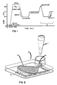
- Nucleic acid amplification generally proceeds via the following steps (shown in Figure 1):
- 1) If DNA is to be amplified, a complete DNA double helix is optionally chemically excised, using an appropriate restriction enzyme(s), to isolate the region of interest.
- 2) A solution of the isolated nucleic acid portion (here, DNA) and nucleotides is heated to and maintained at 92° - 95°C for a length of time, e.g., no more than about 10 minutes, to denature the two nucleic acid strands; i.e., cause them to unwind and separate and form a template.
- 3) The solution is then cooled through a 50° - 60°C zone to cause a primer nucleic acid strand to anneal or "attach" to each of the two template strands. To make sure this happens, the solution is held at an appropriate temperature, such as about 55°C for about 15 seconds, in an "incubation" zone.
- 4) The solution is then heated to and held at about 70°C, to cause an extension enzyme, preferably a thermally stable enzyme such as a polymerase isolated from thermus aquaticus, to extend the primer strand bound to the template strand, by using the nucleotides that are present.
- 5) The completed new pair of strands is heated to 92° - 95°C again, for about 10 - 15 seconds, to cause this pair to separate.
- 6) Steps 3) - 5) are then repeated, a number of times until the appropriate number of strands are obtained. (See, e.g., U.S. Patent 4,683,202 for further illustration.) The more repetitions, the greater the number of multiples of the nucleic acid (here, DNA) that is produced. Preferably the desired concentration of nucleic acid is reached in a minimum amount of time.
- A cuvette is usually used to hold the solution while it passes through the aforementioned temperature stages. Depending upon the design given to the cuvette, it can proceed more or less rapidly through the various stages. A key aspect controlling this is the thermal transfer efficiency of the cuvette- -that is, its ability to transfer heat more or less instantaneously to or from all of the liquid solution within the cuvette. The disposition and the thermal resistance of the liquid solution itself are the major aspects affecting the thermal transfer, since portions of the liquid solution that are relatively far removed from the heat source or sink, will take longer to reach the desired temperature.
- The crudest and earliest type of cuvette used in the prior art is a test tube, which has poor thermal transfer efficiency since a) the walls of the cuvette by being glass or plastic, do not transfer thermal energy well, and b) a cylinder of liquid has relatively poor thermal transfer throughout the liquid. That is, not only does the liquid have low thermal conductivity, but also a cylinder of liquid has a low surface to volume ratio, that is, about 10.6 cm⁻¹ (27 in⁻¹) for a fill of about 100 µl.
- Still another problem in DNA amplification is the manner in which the cuvette allows for ready removal of the liquid after reaction is complete. A test tube configuration readily permits such removal. However, modification of the cuvette to provide better thermal transfer efficiency tends to reduce the liquid transferability.
- Recent cuvette or vessel constructions for reaction of liquid are shown in U.S. Patent Nos. 4,426,451 issued January 17, 1984 and 3,691,017 issued on September 12, 1972. In the former, little attempt is made to provide high thermal transfer efficiency, except that the liquid is distributed as a thin film that will allow rapid heating, if heat penetrates to the liquid. However, no mention is made of the cuvette being constructed of metal or any material that is highly thermally conductive. Furthermore, since the spacing between top and bottom walls is no greater than 125 microns to provide a strong capillary effect, removal of liquid from such cuvette will be difficult. At best, not all the liquid will be removed because of the strong capillary attraction.
- In the case of cuvettes of U.S. Patent No. 3,691,017, more features suitable for DNA amplification are provided. For example, by having a spacing of about 5 mm between major surfaces, it is more readily possible to remove all of the liquid, there being less capillary attraction left at such a gross spacing. In addition, a metal layer is provided on the outside of the cuvette to provide contact with a heating device. However, this cuvette does not have a low thermal time constant for several reasons. One reason is that to ensure transparency, the major surfaces are not constructed of metal, but rather of an insulator. As a result, a long thermal transfer path is needed by extending the metal layer around the edge of the device and into only a portion of the volume of the cuvette. This thermal path length is well in excess of 0.5 mm since it is much more than the thickness of the wall providing either major surface. Indeed, only a portion of the volume of the cuvette is in direct contact with the metallic thermal-energy transfer element.
- Secondly, and more importantly, there is a high thermal resistance in the cuvette of US Patent No. 3691017 because of the low fluid surface/volume ratio provided by cavity geometry, discussed hereinafter in detail.
- Thus, prior to this invention there has been an unsolved problem of providing a cuvette with rapid thermal transfer characteristics, as measured by its thermal time constant when filled with the liquid of choice, such as would be suited for replication of portions of DNA.
- In accord with one aspect of the invention, the above problem is addressed by a thermal cycling cuvette for controlled reaction of components of a liquid involving cycling through a temperature range of at least 35°C, said cuvette having at least one liquid-confining chamber defined by two spaced-apart opposing walls each providing a major surface of contact, side walls connecting said two opposing walls with a spacing between said opposing walls of no less than 0.5 mm, and means permitting the introduction of liquid into, and the removal of such liquid from, said chamber;
characterised in that said opposing walls and said side walls are dimensioned to provide a predetermined surface-to-volume ratio of said chamber, at least one of said opposing walls being provided with a predetermined thermal path length and thermal resistance such that said ratio, path length and thermal resistance are effective to provide, for pure water contained within said chamber in contact with said opposing walls, a thermal time constant for such water that is no greater than 10 seconds, for a liquid volume of no more than 200 µl. - Advantageously, said predetermined surface-to-volume ratio is between 25.6 cm⁻¹ (65 in⁻¹) and 51 cm⁻¹ (130 in⁻¹) for a fill volume of between 100 and 200 µl.
- It is preferred that said thermal path length is no more than 0.3 mm and said thermal resistance is no more than 0.01°C/watt.
- Preferably, said permitting means includes a liquid access aperture, an air vent, and a movable valve for selectively sealing off fluid flow between a) each of said access aperture, and b) said chamber.
- A portion of said valve may be rotatably mounted in the cuvette, and means for rotating said valve portion about an axis may also be provided, said access aperture and said air ven being rotationally oriented about said axis to cooperate with rotation of said valve portion to open and close said access aperture and said air vent.
- Alternatively, said valve may be translatably mounted within the cuvette, and biasing means may be provided for biasing said valve to a closed position wherein said access aperture and said vent are fluidly disconnected from said chamber.
- In one embodiment of the present invention, the cuvette further includes a second liquid-confining chamber defined by two spaced-apart opposing walls, side walls connecting said second chamber two opposing walls, means permitting the introduction of liquid into said second chamber from said first chamber, and means permitting the removal of such liquid out of said second chamber; said chambers further providing a major plane of liquid containment, the major plane of one of said chambers being disposed above the major plane of the other of said chambers.
- Thus, it is an advantageous feature of the invention that rapid thermal energy transfer occurs in and out of the cuvette and its liquid contents, permitting the liquid to undergo multiple temperature changes as needed for the desired reaction. As a result, a required number of repetitive cycles can be achieved in less time than has been heretofore possible.
- It is a related advantageous feature of the invention that a cuvette is provided which allows rapid thermal processing of DNA strands through a multizoned cycle requiring many heat-and-cool repetitions.
- It is still another related advantageous feature of the invention that such a cuvette and its liquid has a reduced thermal time constant, requiring very little delay just to heat up or cool down the liquid.
- It is another advantageous feature of the invention that such a cuvette also permits relatively easy withdrawal of the complete liquid contents, once the reactions are complete.
- Another advantageous feature of the invention is the provision of such a cuvette in which the contents can be readily sealed from exposure to the atmosphere.
- Still another advantageous feature of the invention is the provision of such a cuvette with two chambers and with a minimum of length and width.
- The present invention will now be described by way of example with reference to the accompanying drawings, in which:
- Figure 1 is a graph plotting typical temperature changes for a cuvette in which DNA replication is occurring;
- Figure 2 is an isometric view of a cuvette prepared in accordance with the invention;
- Figure 3 is a plan view of the cuvette of Figure 2;
- Figure 4 is a section view taken generally along the line IV-IV of Figure 3;
- Figure 5 is an enlarged, sectioned fragment taken from the encircled portion of the cuvette, labeled "V", in Figure 4;
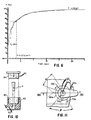
- Figure 6 is a plot of an actual time-temperature response of such a cuvette, to obtain the thermal time constant thereof;
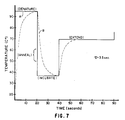
- Figure 7 is a plot of the heating response curve that such a cuvette will have, in light of the data of Figure 6;
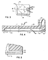
- Figures 8 and 9 are sectional views similar to that of Figure 4, but illustrating two different embodiments;
- Figure 10 is a fragmentary sectional view similar to Figure 4, illustrating the cooperation of both a pipette and a seal, with the cuvette.
- Figure 11 is a fragmentary plan view of an alternate embodiment, particularly of the valving mechanism;
- Figure 12 is a section view taken generally along the line XII-XII of Figure 11;
- Figure 13 is a fragmentary plan view similar to that of Figure 11, but with the valve rotated about 45°;
- Figure 14 is a section view similar to Figure 12, but illustrating the valve rotated as noted for Figure 13, and taken along the line XIV-XIV of Figure 13;
- Figure 15 is a section view similar to that of Figure 12, but of still another embodiment;
- Figure 16 is a plan view of another embodiment of the invention partially broken away;
- Figure 17 is a section view taken generally along the line XVII-XVII of Figure 16;
- Figure 18 is a section view similar to that of Figure 17, but illustrating yet another embodiment;
- Figure 19 is a schematic illustration of an incubating apparatus that is useful in cycling the cuvette through its DNA processing temperatures;
- Figure 20 is a section view similar to Figure 17, of still another embodiment; and
- Figure 21 is a section view taken generally along the line of XXI - XXI of Figure 20.
- The invention is described hereinafter preferably for temperature cycling over a range of at least 35°C, as is particularly useful in replicating DNA strands. In addition, it is also useful for any kind of reaction of liquid components and reagents that requires repetitive heating and cooling of the cuvette within which the reaction is conducted.
- Orientations such as "up", "down", "above" and "below" are used with respect to the cuvette as it is preferably used.
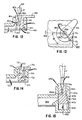
- Turning first to Figures 2-4, a
cuvette 30 constructed in accord with the invention comprises a liquid-confiningchamber 32 defined by two opposingwalls 34 & 36, Figure 4, spaced apart a distance t₁. Such spacing is achieved byside walls chamber 32. Most preferably, the shape ofside walls end 42 at an angle alpha of about 90°, and at a point halfway between ends 42 and 44, start to reconverge again at an angle of about 90°. Distance t₁, Figure 4, is selected such that such distance, when considered in light of the shape ofsidewalls walls - The volume to be emptied varies from 200 to 100 µl. The acceptable times are from 1 to 10 secs. Thus, V ranges between

as a maximum and
as a minimum. For purposes of the invention, A is assumed to be about 5.2 x 10⁻³cm², the flow-through area ofexit 60. Thus, V ranges between about 1.9 cm/sec and about 38.5 cm/sec. In turn, then, the capillary number for this cuvette is between about 0.0003 and about 0.006. However, this must be coupled with a non-capillary spacing, since only that spacing allows such a rate of emptying to occur. -
Walls chamber 32 is optimized for a high rate of thermal energy transfer. A highly preferred example is the exposed surface area of 2.4 cm² (0.37 in²) for each ofwalls - Such a large fluid surface-to-volume ratio provides an advantage apart from a rapid thermal energy transfer. It also means that, for a given volume, a much larger surface area is provided for coating reagents. This is particularly important for reagents that have to be coated in separate locations on the surface to prevent premature mixing, that is, mixing prior to injection of liquid within the chamber. Also, a more effective dissolution occurs for those reagents when liquid is introduced.
- Optionally, therefore, one or more reagent layers 50 can be applied to the interior surface of
wall 36, Figure 4, in a form that will allow the one or more layers to enter into a reaction with liquid sample inserted intochamber 32. Thus "a reagent" is a substance that will interact physically or chemically with the liquid sample. Such reagent layer can be applied in conventional ways, such as by spraying and drying. Such reagents can include a polymerase enzyme, salts, buffers and stabilizers. The coated layer may also include primer-pairs and dinucleotides necessary for replication. - A
liquid access aperture 60 is formed inwall 36adjacent end 42. The aperture has anupper portion 62 and alower portion 64 that connects the upper portion withchamber 32. Preferably atleast portion 62 is conical in shape, the slope of which allows a large number of different conical pipette designs P, Figure 2, to mate therewith. - At
opposite end 44, anair vent 70 is provided, in a manner similar to that described in U.S. Patent No. 4,426,451. Most preferably,air vent 70 extends into apassageway 72, Figure 3, that is routed back to a pointadjacent end 42, where it terminates in opening 74adjacent access aperture 60. - To allow a single closure device to seal both the
access aperture 60 andopening 74 of the air vent, both of these are surrounded by a raised,cylindrical boss 80. Any conventional closure mechanism is useful withboss 80, for example, astopper 82, Figure 10. Such stopper can haveexternal threads 84 for engaging mating internal threads, not shown, on the boss, or it can be constructed for a force fit within theboss 80. - Most preferably, except for
wall 34 described below, the walls of the device are formed from less wettable materials, such as polycarbonate plastics materials. - In accord with one aspect of the invention, the
wall 34 opposite to wall 36 is constructed with a predetermined thermal path length and thermal resistance that will provide a high rate of thermal energy transfer. Most preferably, such path length (t₂ in Figure 5) is no greater than about 0.3 mm, and the thermal resistance is no greater than about 0.1°C/watt. These properties are readily achieved by constructingwall 34 out of a metal such as aluminum that is about 0.15 mm thick. Such aluminum has a thermal resistance R, calculated as thickness χ·1/(thermal conductivity K·surface area A), which is about 0.003°C/watt. (These values can be contrasted for ordinary glass of the same thickness, which has a thermal resistance of about 0.24°C/watt.)
Wall 34 can be secured to sidewalls 38 and 40 by any suitable means. One such means is alayer 90, Figure 5, of a primer, which comprises for example a conventional high temperature acrylic adhesive, followed bylayer 92 of conventional polyester adhesive. In some instances, layers 90 and 92 need not extend over the surface area ofwall 34, as such would increase the thermal resistance ofwall 34, and possibly interfere with reactions described withinchamber 32. On the other hand, it will be apparent that some reactions can equally be adversely affected by metal ions present and for these reactions, the adhesive coats the entire surface area ofwall 34. - A cuvette constructed as described above for Figures 2-4, has been found to produce a thermal time constant tau (τ) for its contained liquid that is no greater than about 10 seconds. Most preferred are those in which τ is of the order of 3-8 seconds. That is, Figure 6, when such a cuvette, filled with water, is heated along the exterior of
wall 34, and its temperature is measured at point Y, Figure 4, a thermal response curve is generated from 28°C to a final temperature of 103.9°C. The time it takes for the liquid therein to reach a temperature of 76°C (the initial temperature of 28°C plus 63% of the difference (103.9 - 28)) is the approximate value of tau (τ). This derives (approximately) from the well-known thermal response equation:

Thus, if the time interval t in question equals tau, then e-t/τ = e⁻¹≃ 0.37. In such a case, T (t) (at t = tau) is the temperature which is equal to the initial temperature, plus 63% of (Final Temperature - Initial Temperature). (The step-wise shape of the data in Figure 6 is an artifact of the recorder.)
Therefore, tau for the liquid of that cuvette is about 3.5 seconds (assuming that the response curve of Figure 6 obeys the equation (1) above, which it does to a sufficiently close approximation). - If the adhesive of
layers wall 34, then tau can be increased to as much as 7 or 8 sec. - With a value of tau equal to about 3.5 sec, the thermal response curve of the same cuvette can be predicted under the conditions it will be subjected in accordance with the protocol of Figure 1. Figure 7 is such a response curve, generally for only the last segment of Figure 1 marked "X", where the stepped portions "A" are the oven or incubator temperatures, and the curve "B" is the temperature of the liquid contents, for tau ≃ 3 seconds. (However, in this example, the incubation temperature was selected to be 37°C instead of 55°C.)
- As a comparative example, the cuvette described in U.S. Patent No. 3,691,017 has the following properties. Its overall thickness (col. 8, lines 42-44) is 7.94 mm (5/16 in or 0.31 in). The space occupied by the liquid has a thickness of 5 mm (
line 44, col. 8). The window is 12.7 mm (1/2 in) by 6.35 mm (1/4 in) (line 45), so that the volume of the liquid of a unit area of one square inch, is estimated to be about 3.23 cm³ (0.197 in³), and its surface area contacting the cuvette is estimated to be about 18 cm² (2.79 in²). This produces at best a surface/volume ratio of only about 5.6 cm⁻¹ (14.2 in⁻¹). A sphere of the same volume has a S/V ratio of 3.27 cm⁻¹ (8.3 in⁻¹), indicating that the cuvette is only slightly better in its S/V ratio than the worst possible configuration (the sphere). In addition, the heating element is a foil of aluminum that has to extend into the cavity from the outside, thus producing a thermal path length well in excess of 1 mm. All of this clearly indicates that the thermal time constant tau of water in such a cuvette is substantially greater than 10 sec. - It is not necessary that the cuvette be assembled using adhesive. A non-adhesive embodiment is illustrated in Figure 8, wherein parts similar to those used in the previous embodiment bear the same reference numeral to which is appended the letter "a". Thus, cuvette 30a comprises two
opposed walls 34a and 36a which, with side walls (of which only 40a is shown), define achamber 32a. Aliquid access aperture 60a and an air vent 70a are provided, also as in the previous embodiment, and wall 34a has the same properties as discussed above. However, in this embodiment there are no adhesive layers between wall 34a andside wall 40a at any point. Instead, around the entire edge ofchamber 32a, there is agasket seal 100 of an elastomer, or other suitable gasket material, between wall 34a and the side wall. In addition, bumps 110 of plastics material extend from the side walls through appropriate openings in the wall 34a.Bumps 110 are then upset by heat or pressure to rivet wall 34a in place. Optionally, gasket seals 100 can also extend around such bumps. - When the access aperture and the air vent are sealed, and the cuvette is heated, pressure builds within
chamber reaction vessel wall 34 and 34a and the incubator. Still further, deformation of some other wall reduces the strain on the seal that holds the thermally conductive wall in place. Such an embodiment is shown in Figure 9, as described and claimed in our copending European Patent Application No. 88311060.3. Parts similar to those previously described bear the same reference numeral, to which the distinguishing suffix "b" is appended. - Thus,
cuvette 30b comprises opposedwalls wall 40b shown), achamber 32b having a spacing t₁. These and theaccess aperture 60b andair vent 70b are constructed as in either of the previous embodiments. However, to insure thatwall 34b does not deform under pressure,wall 36b is constructed to have a flexure strength that is less than that ofwall 34b. Specifically, this is preferably done as follows: ifwall 34b comprises aluminum that is about 0.15 mm thick, then its flexure strength K at the center of flexure is determinable, based on the following: - Deflection X is determined by the well known equation

where P = total applied load, E = plate modulus of elasticity, t = plate thickness, a = the length of one side of the plate, and α is an emperical coefficient (usually equal to about 0.015).
Rearranging,

Because P/X is analogous to F/X which equals K, then

This allows K to be calculated to be about 6.11 x 10⁴ N/m (6.11 x 10⁶ dynes/mm). Forwall 36b to have a flexure strength less than that, it need only comprise a layer of polyethylene or polypropylene that is about 0.3 mm thick (thickness t₃ that is twice that of thealuminum wall 34b), to have a flexure strength of about 8.3 x 10³ N/m (8.3 x 10⁵ dynes/mm), calculated in the same manner. In such a construction,wall 36b will dome upwardly as pressure is generated withinchamber 32b, leavingwall 34b lying planar against the heating element (shown in phantom as "E"). - In use, any of the above-described embodiments is filled to about 90% of being full, with a liquid containing the desired sample for reaction, for example, a solution of a DNA sequence that is to be amplified. The device is then inserted into an appropriate incubator and cycled through the necessary stages for the reaction.
- In accord with another aspect of the invention, a movable valve is disposed to selectively open and close access to the chamber within the cuvette. Parts similar to those previously described bear the same reference numeral to which the distinguishing letter "c" has been appended.
- Thus, in Figures 11-14,
end 42c ofchamber 32c has both theliquid access aperture 60c and theair vent passageway 72c located adjacent to each other, within raisedboss 80c, Figure 11.Upper portion 62c is conically shaped, as in previous embodiments, to allow a mating engagement of pipette P, Figure 12. - However, in this embodiment a valve is provided, comprising a
rotatable portion 120 mounted within a mating conically shapedaperture 122, Figure 12.Rotatable portion 120 has an exterior, conically shapedsurface 123. The valve has an axis ofrotation 124, preferably concentrically disposed withinaperture 60c. Ahandle 126 permits manual or automated rotation of the valve. Both theaccess aperture 60c, as well asair vent opening 74c, are located in themovable valve portion 120, Figures 11 and 13. - To selectively connect
aperture 60c andopening 74c tochamber 32c, two paths are formed inrotatable portion 120.Path 130 extends fromaperture 60c to theexterior surfaces 123, Figure 12, where it is open over an angle ϑ of that surface, Figure 11. Path 132 extends, Figure 14, fromaperture 74c to anexit 134 onsurface 123. The heights of thepaths 130 and 132, relative to thechamber 32c andpassageway 72c, respectively, are such as to allow the paths to be fluidly connected to the chamber or passageway, whenrotatable portion 120 is rotated to the position shown in Figure 13. In addition, because of the angle theta (ϑ) of access provided bypath 130,portion 120 can be rotated also to a position (not shown) wherein only theaccess aperture 60c is in fluid communication withchamber 32c, if desired. - A
tail portion 140 holdsrotatable portion 120 vertically in place, and rides in aslot 144, Figure 12. - The access and air vent valve need not be rotatable. Translatable valves are also useful. Parts similar to those previously described bear the same reference numeral to which the distinguishing suffix "d" is appended.
- Thus, in Figure 15,
valve portion 120d is disposed atend 42d so as to incorporate both theaccess aperture 60d andair vent opening 74d. However, unlike the previous embodiment,portion 120d is vertically, translatably mounted, withtail portion 140d riding vertically in aslot 144d that permits no rotation. Aspring 150biases portion 120d so that, normally, it is raised to misalignpaths chamber 32d and ventpassageway 72d, respectively, thus sealing offchamber 32d from the outside environment. To access the chamber, the user need only press down onportion 120d, such as by engagingaccess aperture 60d with a pipette P, and push againstspring 150. -
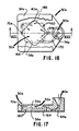
Vent opening 74d is, in this embodiment, a groove formed inexterior surface 123d, which allows venting ofpassageway 72d whenportion 120d is pushed down a distance sufficient to fluidly connectchamber 32d also withaperture 60d. - In certain reactions, it is desirable that the liquid be moved to a second chamber, after an appropriate residence time in the first chamber. For example, DNA probe assays require a single, additional, new thermal cycle with which to bond DNA probes to the amplified target sequence. Subsequent to the DNA amplification temperature cycling discussed above, the DNA-bearing broth is brought into contact with DNA probes specific to the amplified target sequence. Such probes can be coated onto the walls of a reaction vessel, and more specifically, on the walls of a second, DNA probe bearing chamber, as shown in Figures 16-17. Parts similar to those previously described, bear the same reference numeral to which the distinguishing suffix "e" is appended.
- Thus,
cuvette 30e compriseschamber 32e disposed between two opposingwalls side walls access aperture 60e,air vent 70e andair vent opening 74e. However, unlike the previous embodiments,metallic wall 34e is above, rather than below,chamber 32e, Figure 17, so that heat is applied downwardly fromabove cuvette 30e. (A filter membrane, not shown, can be optionally positioned at 70e.)
This rearrangement ofwalls second chamber 160 is provided, disposed underneathchamber 32e. That is, each of the two chambers provides a major plane of liquid containment, and preferably, has a generally planar configuration due to the opposing walls of primary surface area being also generally planar and respectively coplanar. Thus, the major containment plane ofchamber 32e is disposed above the major containment plane ofchamber 160. - As is apparent in Figure 17,
chamber 160 has an opposing, primary surface wall that is infact wall 36e. Theopposite wall 164 is the wall that provides the thermal energy transfer, by being constructed substantially the same aswall 34e.Side walls chamber 160 as in the case ofchamber 32e,except thatchamber 160 is rotated about 45° with respect tochamber 32e, so that its air vent, described below, does not conflict with thelower portion 64e ofaccess aperture 60e. - An air vent and
passageway 170 is provided forchamber 160, Figure 16. It is constructed similar to the air vent passageway of the air vent of previous embodiments. Alternatively, not shown,air vent opening 74e can be shaped and positioned to allow direct removal of liquid fromchamber 160, without requiring it to be withdrawn back throughchamber 32e as shown in Figure 16. - In use, liquid in
chamber 32e is forced to flow intochamber 160, as per the arrows in Figure 17, by injecting either air pressure intochamber 32e through the access aperture, or, e.g., solutions optionally containing reagents for further reaction in the cuvette, or by pulling a vacuum onchamber 160. - Alternatively, the two chambers can overlie each other with side walls that are exactly aligned, rather than offset by 45°. This embodiment is shown in Figure 18, wherein parts similar to those previously described bear the same reference numeral to which the distinguishing letter "f" is appended.
- Thus,
cuvette 30f comprises upper andlower chambers common wall 36f that is not a thermal transfer wall. Air vent 70f feeds liquid fromchamber 32f to 160f, andwalls 34f and 164f provide the necessary rapid transfer of thermal energy. Unlike the previous embodiment, however, sidewalls (40f ofchamber 32f being shown) are aligned with the sidewalls ofchamber 160f (wall 166f being shown). This is rendered possible by rotatingboss 80f 90° so as to provideaccess aperture 60f that is totally within the major plane of liquid confined bychamber 32f. In such a cuvette,air vent 170f and its opening 74f are located within the major plane of liquid confined withinchamber 160f. - In each of the two embodiments of Figures 16-18, the advantage achieved is that the length or width of the cuvette is not extended appreciably beyond that of the cuvette of Figure 2, as it would be if the two major planes of liquid confinement were coplanar. Only the vertical thickness is slightly increased to permit the two chambers to be vertically stacked to provide a three-dimensional flow.
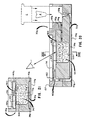
- Yet another useful configuation is one shown in Figures 20 and 21, in which a third liquid-confining chamber is fluidly connected to said second chamber, with a liquid-permeable membrane isolating and separating the third chamber from the second chamber. Parts similar to those previously described bear the same reference numeral, to which the distinguishing suffix "g" is appended.
- Thus,
cuvette 30g comprises afirst chamber 32g having opposingwalls wall 34g is metallic),sidewalls access aperture 60g.Chamber 32g leads via passageway orair vent 70g to thesecond chamber 160g, disposed in a major plane of configuration that is parallel to that plane of configuration occupied bychamber 32g, as in the embodiment of Figure 16. However, in this embodiment,chamber 160g is abovechamber 32g, rather than below it.Chamber 160g is defined in part by opposingwalls wall 136 being preferably a buckling, preferably transparent, wall as in the case ofwall 36b in the embodiment of Figure 9.Wall 136 is also preferably recessed belowsurface 137, so as to protect the exterior surface ofwall 136 from scratching.Chamber 160g is also defined by a liquid-permeable membrane 300 having anupper surface 302 facing intochamber 160g. Alower surface 304 of the membrane faces away fromchamber 160g. Useful materials for this membrane include cast, woven or electro-optically machined, microfiltration membranes.Sidewalls 166g and 168g, Figure 21, complete that chamber. - A
third chamber 310 is fluidly connected tochamber 160g viamembrane 300, so thatchamber 310 is isolated and separated from the other two chambers by the membrane. Preferably,chamber 310 is formed within the block located betweenwalls chamber Air vent passageway 170g leads fromchamber 310 toair vent opening 74g located withinboss 80g, as in previous embodiments. In addition, an air vent (not shown) containing a liquid-impermeable but air-permeable plug, extends fromchamber 160g toboss 80g, in a location that is generally abovepassageway 170g. - Most preferably, a liquid-absorbing
material 320 is disposed withinchamber 310, to fill the chamber and preferably contactlower surface 304 ofmembrane 300. - A preferred use of
cuvette 30g is to trap and identify a particular nucleic acid sequence, such as of DNA, amplified within the cuvette. To this end,surface 302 preferably includes means for capturing proteinaceous materials capable of bonding to a DNA strand. Such capture proteins are conventional and comprise a complementary sequence of nucleotides that bond to the DNA sequence of choice, the sequence having attached to it any appropriate means for bonding to the membrane. For example, such bonding means can be one of a pair of avidin and biotin, as is conventional. The other of the pair is bonded tosurface 302. - The method of use of
cuvette 30g will be apparent from the preceding, and generally is as follows:
Chamber 32g contains in pre-prepared form most or all of the reagents needed for DNA amplification. The DNA-containing liquid is injected via pipette P, to only partially fillchamber 32g, and cap C is screwed into place or otherwise attached. Denaturing, incubating, and replicating proceed as in the other embodiments. Subsequently, pipette P is used again to inject intochamber 32g, the capture probes discussed above, and also detection probes. Such detection probes are also conventional, and comprise a protein and complementary nucleotides that attaches to the DNA strand of choice opposite to the end to which the capture probe attaches. The detection probe also includes any appropriate signal-generating moiety, for example, horseradish peroxidase, capable of reacting with a leuco dye to produce a detectable signal (e.g., a color change.) The technology for attaching two different probes at the opposite 3′ and 5′ end is known. For example in "Efficient Methods for Attachment of Thiol Specific Probes to the 3′ End of Synthetic Oligodeoxyribonucleotides", Vol. 15 of Nucleic Acids Research, p. 5305 (1987), the techniques useful for the 3′ end attachment are discussed. The articles discussing 5′ end attachment are legion, for which the following is only representative: "Introduction of 5′ Terminal Functional Groups. . . .", Vol. 164 of Analytical Biochemistry, p.336 (1987). It will be readily apparent that either the 3′ or the 5′ end is used to attach one of the two probes, and the other end is used to attach the other of the two probes. - Alternatively, the detection probe and the immobilizing probe can be one and the same, attached at, say, just the 5′ end, using the techniques taught in the aforesaid Analytical Biochemistry article.
- The cuvette, now containing both probes as well as the amplified DNA, is agitated or shaken, to promote mixing.
- Thereafter, portion "X" of the cycle shown in Figure 1 is repeated in order to cause the two probes to attach to separate strands of DNA.
- Following this step, the liquid, still in
chamber 32g, is pushed uppassageway 70g intochamber 160g. This pushing step is achieved by injecting via pipette P either additional liquid, or air, or by pulling a vacuum atvent opening 74g. If a liquid is used, a neutral solution (containing no active ingredients) is used. The liquid is allowed to incubate inchamber 160g, preferably by closing offvent opening 74g with cap C. - Thereafter, all the liquid is drawn off through
membrane 300 into absorbingmaterial 320. This is done either by an additional pulse of air being injected, by assisting the natural flow of liquid throughmembrane 300 by applying a partial vacuum to opening 74g or by capillary attraction ofabsorbent material 320. At this point, the capture and detection probes have bonded, as a result of the replication part of portion X of the cycle, to the DNA strand, and the capture probe is captured by thesurface 302 of the membrane. Any DNA strands lacking the capture probe pass throughmembrane 300 and are absorbed bymaterial 320. - The final step is to inject into
chambers surface 302. Useful leuco dyes include those set forth in U.S. Patent No. 4,089,747, preferably in combination with a solubilizing polymer such as poly(vinyl pyrrolidone). A preferred example of the dye is 2-(4-hydroxy-3,5-dimethoxyphenyl)-4,5-bis(4-methoxyphenyl)imidazole, since this gives about 1000 dye molecules per 1 molecule of horse radish peroxidase. - As an alternative to the above, capture probes bounded to beads, also conventional, can be used. The beads are selected with a diameter that is too large to pass through the pores of
membrane 300. - Any suitable incubator is useful to cycle the cuvettes of this invention through the desired heating and cooling stages. Most preferably, the incubator provides stages that cycle through the temperatures shown in Figure 1. A
convenient incubator 200 for doing this is one having the stations shown in Figure 19. Apreincubate station 202 has heating means that establishes a temperature of approximately 95°C. From here, the cuvette is pushed by conventional pusher means onto aring 210 of constant temperature stations, the first one 212 of which is maintained at 55°C. From this station the cuvette is shuttled tostation 214, which heats it to 70°C. This temperature is maintained for a period, and accordingly station 216 is also at that temperature. Next, a short-time denaturing station 218 is encountered to denature the newly replicated DNA, which station is maintained at 95°C. Stations 220-234 simply repeat twice more the cycles already provided by stations 212-218. Afterstation 234 is encountered, and if all amplication is complete, a conventional transfer mechanism (not shown) moves the cuvette offring 210 for further processing. (Both the injection of liquid into the cuvette and the removal of liquid therefrom are done off-line, that is, outside ofincubator 200.) If further amplification is needed, a particular cuvette continues around the incubator for additional cycles.
Claims (24)
- A thermal cycling cuvette (30; 30a; 30b; 30e; 30f; 30g) for controlled reaction of components of a liquid involving cycling through a temperature range of at least 35°C, said cuvette (30; 30a; 30b; 30e; 30f; 30g) having at least one liquid-confining chamber (32; 32a; 32b; 32c; 32d; 32e; 32f; 32g) defined by two spaced-apart opposing walls (34, 36; 34a, 36a; 34b, 36b; 34e, 36e; 34f, 36f; 34g, 36g) each providing a major surface of contact, side walls (38, 40; 40a; 40b; 38e, 40e; 40f; 38g, 40g) connecting said two opposing walls (34, 36; 34a, 36a; 34b, 36b; 34e, 36e; 34f, 36f; 34g, 36g) with a spacing (t₁) between said opposing walls (34, 36; 34a, 36a; 34b, 36b; 34e, 36e; 34f, 36f; 34g, 36g) of no less than 0.5 mm, and means (60, 62, 64; 60a; 60b; 60c, 62c; 60d; 60e, 64e; 60f; 60g) permitting the introduction of liquid into, and the removal of such liquid from, said chamber (32; 32a; 32b; 32c; 32d; 32e; 32f; 32g);
characterised in that said opposing walls (34, 36; 34a, 36a; 34b, 36b; 34e, 36e; 34f, 36f; 34g, 36g) and said side walls (38, 40; 40a; 40b; 38e, 40e; 40f; 38g, 40g) are dimensioned to provide a predetermined surface-to-volume ratio of said chamber (32; 32a; 32b; 32c; 32d; 32e; 32f; 32g), at least one of said opposing walls (34; 34a; 34b; 34e; 34f; 34g) being provided with a predetermined thermal path length (t₂) and thermal resistance such that said ratio, path length and thermal resistance are effective to provide, for pure water contained within said chamber (32; 32a; 32b; 32c; 32d; 32e; 32f; 32g) in contact with said opposing walls (34, 36; 34a, 36a; 34b, 36b; 34e, 36e; 34f, 36f; 34g, 36g), a thermal time constant for such water that is no greater than 10 seconds, for a liquid volume of no more than 200 µl. - A cuvette as defined in claim 1, wherein said predetermined surface-to-volume ratio is between 25.6 cm⁻¹ (65 in⁻¹) and 51 cm⁻¹ (130 in⁻¹) for a fill volume of between 100 and 200 µl.
- A cuvette as defined in claim 1 or 2, wherein said thermal path length (t₂) is no more than 0.3 mm and said thermal resistance is no more than 0.01°C/watt.
- A cuvette as defined in claim 2 or 3, wherein said opposing walls (34, 36; 34a, 36a; 34b, 36b; 34e, 36e; 34f, 36f; 34g, 36g) and said side walls (38, 40; 40a; 40b; 38e, 40e; 40f; 38g, 40g) are spaced so that water can be effectively withdrawn in no longer than 10 seconds with a capillary number of less than 0.05.
- A cuvette as defined in claim 3, wherein said spacing (t₁) between said opposing walls (34, 36; 34a, 36a; 34b, 36b; 34e, 36e; 34f, 36f; 34g, 36g) is from 0.5 mm to 2.5 mm.
- A cuvette as defined in any one of the preceding claims, wherein the structural component of at least one of said opposing walls (34; 34a; 34e; 34f; 34g) comprises aluminum no thicker than 0.15 mm.
- A cuvette as defined in any one of the preceding claims, wherein at least one entire surface of one of said opposing walls (34; 34a; 34e; 34f; 34g) of said chamber (32; 32a; 32b; 32c; 32d; 32e; 32f; 32g) has a thermal resistance of no more than 0.01°C/watt.
- A cuvette as defined in any one of the preceding claims, and further including a reagent coated over at least one of said opposing walls (34, 36; 34a, 36a; 34b, 36b; 34e, 36e; 34f, 36f; 34g, 36g).
- A cuvette as defined in claim 8, wherein said one opposing wall (36; 36a; 36b; 36e; 36f; 36g) is opposite to said opposing wall (34; 34a; 34b; 34e; 34f; 34g) having said thermal path length.
- A cuvette as defined in any one of the preceding claims, wherein said permitting means (60, 62, 64; 60a; 60b; 60c, 62c; 60d; 60e, 64e; 60f; 60g) includes means defining a liquid access aperture (60; 60a; 60b; 60c; 60d; 60e; 60f; 60g).
- A cuvette as defined in claim 10, and further including an opening (80; 80e; 80f; 80g) constructed to be larger than said liquid access aperture (60; 60a; 60b; 60c; 60d; 60e; 60f; 60g), to receive closure means (82) for sealing said larger opening (80; 80e; 80f; 80g), and wherein said aperture (60; 60a; 60b; 60c; 60d; 60e; 60f; 60g) is located within said larger opening (80; 80e; 80f; 80g).
- A cuvette as defined in claim 11, and further including an air vent (70, 72, 74; 70a; 70b; 72c, 74c; 72d, 74d; 70e, 74e; 70f, 74f; 70g, 74g) for said chamber (32; 32a; 32b; 32c; 32d; 32e; 32f; 32g).
- A cuvette as defined in claim 12, wherein said air vent (70, 72, 74; 70a; 70b; 72c, 74c; 72d, 74d; 70e, 74e; 70f, 74f; 70g, 74g) terminates at a location within said larger opening (80; 80e; 80f; 80g).
- A cuvette as defined in claim 10, wherein said liquid access aperture (60, 62, 64; 60a; 60b; 60c, 62c; 60d; 60e, 64e; 60f; 60g) is configured to removably mate with a pipette or pipette tip (P).
- A cuvette as defined in any one of the preceding claims, wherein said permitting means (60c, 62c; 60d) includes a liquid access aperture (60c; 60d), an air vent (74c; 74d), and a movable valve (120, 122, 123, 124, 130, 132; 120d, 130d, 132d, 140d, 114d, 150) for selectively sealing off fluid flow between a) each of said access aperture (60c; 60d) and air vent (74c; 74d), and b) said chamber (32c; 32d).
- A cuvette as defined in claim 15, wherein a portion (120) of said valve (120, 122, 123, 124, 130, 132) is rotatably mounted in the cuvette (30c), and further including means (126) for rotating said valve portion (120) about an axis (124), said access aperture (60c) and said air vent (74c) being rotationally oriented about said axis (124) to cooperate with rotation of said valve portion (120) to open and close said access aperture (60c) and said air vent (74c).
- A cuvette as defined in claim 15, wherein said valve (120d, 130d, 132d, 140d, 114d, 150) is translatably mounted within the cuvette (30d), and further including biasing means (150) for biasing said valve (120d, 130d, 132d, 140d, 114d, 150) to a closed position wherein said access aperture (60d) and said vent (74d) are fluidly disconnected from said chamber (32d).
- A cuvette as defined in any one of the preceding claims, and further including a second liquid-confining chamber (160; 160f; 160g) defined by two spaced-apart opposing walls (36e, 164; 36f, 164f; 36g), side walls (166, 168; 166f, 168f; 166g, 168g) connecting said second chamber two opposing walls (36e, 164; 36f, 164f; 36g), means (70e; 170f; 170g) permitting the introduction of liquid into said second chamber (160; 160f; 160g) from said first chamber (32e; 32f; 32g), and means (74e; 74f; 74g) permitting the removal of such liquid out of said second chamber (32e; 32f; 32g); said chambers (32e, 160; 32f, 160f; 32g, 160g) further providing a major plane of liquid containment, the major plane of one of said chambers being disposed above the major plane of the other of said chambers.
- A cuvette as defined in claim 18, wherein the length and/or width of said cuvette is reduced compared to a comparable cuvette in which said major planes are coplanar.
- A cuvette as defined in claim 18 or 19, and further including a third liquid-confining chamber (310) fluidly connected to said second chamber (160g), and a liquid-permeable membrane (300, 302, 304) separating said third chamber (310) from said second chamber (160g).
- A cuvette as defined in claim 20, and further including a liquid-absorbing material (320) in said third chamber (310).
- A cuvette as defined in claim 20 or 21, and further including on said membrane (300, 302, 304), means for capturing a proteinaceous material capable of bonding to a DNA strand.
- A cuvette as defined in claim 22, wherein said capturing means includes either avidin or biotin, said proteinaceous material having bonded thereto, the other of the avidin/biotin pair.
- A cuvette as defined in any one of the preceding claims, wherein one of said walls is transparent and is recessed to protect it from scratches.
Applications Claiming Priority (4)
| Application Number | Priority Date | Filing Date | Title |
|---|---|---|---|
| US12375187A | 1987-11-23 | 1987-11-23 | |
| US123751 | 1987-11-23 | ||
| US07/273,781 US4902624A (en) | 1987-11-23 | 1988-11-21 | Temperature cycling cuvette |
| US273781 | 1988-11-21 |
Publications (3)
| Publication Number | Publication Date |
|---|---|
| EP0318255A2 EP0318255A2 (en) | 1989-05-31 |
| EP0318255A3 EP0318255A3 (en) | 1990-07-18 |
| EP0318255B1 true EP0318255B1 (en) | 1993-04-28 |
Family
ID=26821857
Family Applications (1)
| Application Number | Title | Priority Date | Filing Date |
|---|---|---|---|
| EP88311059A Expired - Lifetime EP0318255B1 (en) | 1987-11-23 | 1988-11-23 | Cuvette |
Country Status (4)
| Country | Link |
|---|---|
| US (1) | US4902624A (en) |
| EP (1) | EP0318255B1 (en) |
| JP (1) | JPH01266858A (en) |
| DE (1) | DE3880632T2 (en) |
Cited By (3)
| Publication number | Priority date | Publication date | Assignee | Title |
|---|---|---|---|---|
| US5916522A (en) * | 1997-08-07 | 1999-06-29 | Careside, Inc. | Electrochemical analytical cartridge |
| US5919711A (en) * | 1997-08-07 | 1999-07-06 | Careside, Inc. | Analytical cartridge |
| US6002475A (en) * | 1998-01-28 | 1999-12-14 | Careside, Inc. | Spectrophotometric analytical cartridge |
Families Citing this family (102)
| Publication number | Priority date | Publication date | Assignee | Title |
|---|---|---|---|---|
| CA1338505C (en) * | 1989-02-03 | 1996-08-06 | John Bruce Findlay | Containment cuvette for pcr and method of use |
| US6645758B1 (en) | 1989-02-03 | 2003-11-11 | Johnson & Johnson Clinical Diagnostics, Inc. | Containment cuvette for PCR and method of use |
| US5229297A (en) * | 1989-02-03 | 1993-07-20 | Eastman Kodak Company | Containment cuvette for PCR and method of use |
| GB8915680D0 (en) * | 1989-07-08 | 1989-08-31 | Nortech | Heat resistant multiwell plates |
| US5346672A (en) * | 1989-11-17 | 1994-09-13 | Gene Tec Corporation | Devices for containing biological specimens for thermal processing |
| US6787338B2 (en) * | 1990-06-04 | 2004-09-07 | The University Of Utah | Method for rapid thermal cycling of biological samples |
| US5935522A (en) * | 1990-06-04 | 1999-08-10 | University Of Utah Research Foundation | On-line DNA analysis system with rapid thermal cycling |
| US5455175A (en) * | 1990-06-04 | 1995-10-03 | University Of Utah Research Foundation | Rapid thermal cycling device |
| US7081226B1 (en) | 1996-06-04 | 2006-07-25 | University Of Utah Research Foundation | System and method for fluorescence monitoring |
| US7273749B1 (en) | 1990-06-04 | 2007-09-25 | University Of Utah Research Foundation | Container for carrying out and monitoring biological processes |
| EP0533801B1 (en) * | 1990-06-15 | 1994-08-10 | Chiron Corporation | Self-contained assay assembly and apparatus |
| GB9013615D0 (en) * | 1990-06-19 | 1990-08-08 | Wellcome Found | Pharmaceutical compounds |
| DE4022792A1 (en) * | 1990-07-18 | 1992-02-06 | Max Planck Gesellschaft | PLATE WITH AT LEAST ONE RECESS FOR RECEIVING CHEMICAL AND / OR BIOCHEMICAL AND / OR MICROBIOLOGICAL SUBSTANCES AND METHOD FOR PRODUCING THE PLATE |
| US6703236B2 (en) | 1990-11-29 | 2004-03-09 | Applera Corporation | Thermal cycler for automatic performance of the polymerase chain reaction with close temperature control |
| KR100236506B1 (en) * | 1990-11-29 | 2000-01-15 | 퍼킨-엘머시터스인스트루먼츠 | Apparatus for polymerase chain reaction |
| EP0533854A4 (en) * | 1990-12-20 | 1994-06-08 | Hoffmann La Roche | Pcr primers for detection of legionella species and methods for controlling visual intensity in hybridization assays |
| CA2065719A1 (en) | 1991-04-30 | 1992-10-31 | John B. Findlay | Nucleic acid amplification and detection methods using rapid polymerase chain reaction cycle |
| US5994056A (en) * | 1991-05-02 | 1999-11-30 | Roche Molecular Systems, Inc. | Homogeneous methods for nucleic acid amplification and detection |
| US5569582A (en) * | 1991-07-15 | 1996-10-29 | Institute Of Molecular Biology & Technology | Rapid amplification and detection of nucleic acids |
| IL102486A (en) * | 1991-10-04 | 1997-11-20 | Orgenics Ltd | Method and apparatus for detection of nucleic acid sequences with a nucleic acid probe |
| TW313588B (en) * | 1992-10-23 | 1997-08-21 | Eastman Kodak Co | |
| US5840573A (en) * | 1994-02-01 | 1998-11-24 | Fields; Robert E. | Molecular analyzer and method of use |
| US5725831A (en) * | 1994-03-14 | 1998-03-10 | Becton Dickinson And Company | Nucleic acid amplification apparatus |
| CA2143365A1 (en) * | 1994-03-14 | 1995-09-15 | Hugh V. Cottingham | Nucleic acid amplification method and apparatus |
| DE4409436A1 (en) * | 1994-03-19 | 1995-09-21 | Boehringer Mannheim Gmbh | Process for processing nucleic acids |
| US5700695A (en) * | 1994-06-30 | 1997-12-23 | Zia Yassinzadeh | Sample collection and manipulation method |
| US5639428A (en) * | 1994-07-19 | 1997-06-17 | Becton Dickinson And Company | Method and apparatus for fully automated nucleic acid amplification, nucleic acid assay and immunoassay |
| US5622822A (en) | 1994-09-13 | 1997-04-22 | Johnson & Johnson Clinical Diagnostics, Inc. | Methods for capture and selective release of nucleic acids using polyethyleneimine and an anionic phosphate ester surfactant and amplification of same |
| US5705366A (en) | 1994-09-15 | 1998-01-06 | Johnson & Johnson Clinical Diagnostics, Inc. | Coamplification of target nucleic acids using volume exclusion agent in reaction composition, test kit and test device useful therefor |
| US5582988A (en) | 1994-09-15 | 1996-12-10 | Johnson & Johnson Clinical Diagnostics, Inc. | Methods for capture and selective release of nucleic acids using weakly basic polymer and amplification of same |
| ATE212064T1 (en) * | 1994-11-14 | 2002-02-15 | Univ Pennsylvania | DEVICE FOR AMPLIFICATION OF POLYNUCLEOTIDES ON THE MESOM SCALE |
| JPH08196299A (en) * | 1995-01-26 | 1996-08-06 | Tosoh Corp | Thermal cycling reaction apparatus and reaction vessel therefor |
| EP0729021A1 (en) * | 1995-02-25 | 1996-08-28 | Roche Diagnostics GmbH | Device for treating samples on microscope slides |
| JPH0921744A (en) * | 1995-07-06 | 1997-01-21 | Nec Corp | Cell for spectrometer |
| EP0790861A1 (en) * | 1995-09-12 | 1997-08-27 | Becton, Dickinson and Company | Device and method for dna amplification and assay |
| IL118155A (en) | 1996-05-06 | 2000-02-29 | Combact Diagnostic Systems Ltd | Method and device for handling specimens |
| ATE428801T1 (en) * | 1996-06-04 | 2009-05-15 | Univ Utah Res Found | MONITORING HYBRIDIZATION DURING PCR |
| DE69738605T2 (en) * | 1996-06-04 | 2009-04-30 | University Of Utah Research Foundation, Salt Lake City | Container for carrying out and monitoring biological processes |
| GB9616540D0 (en) * | 1996-08-06 | 1996-09-25 | Cavendish Kinetics Ltd | Integrated circuit device manufacture |
| DE19646114B4 (en) * | 1996-11-08 | 2004-09-16 | Eppendorf Ag | Laboratory thermostat with temperature blocks |
| US5958349A (en) * | 1997-02-28 | 1999-09-28 | Cepheid | Reaction vessel for heat-exchanging chemical processes |
| US8293064B2 (en) * | 1998-03-02 | 2012-10-23 | Cepheid | Method for fabricating a reaction vessel |
| AU6343398A (en) | 1997-02-28 | 1998-09-18 | Cepheid | Heat exchanging, optically interrogated chemical reaction assembly |
| US6660228B1 (en) | 1998-03-02 | 2003-12-09 | Cepheid | Apparatus for performing heat-exchanging, chemical reactions |
| US6369893B1 (en) | 1998-05-19 | 2002-04-09 | Cepheid | Multi-channel optical detection system |
| US6723290B1 (en) * | 1998-03-07 | 2004-04-20 | Levine Robert A | Container for holding biologic fluid for analysis |
| US7188001B2 (en) * | 1998-03-23 | 2007-03-06 | Cepheid | System and method for temperature control |
| JP2000304754A (en) * | 1999-02-12 | 2000-11-02 | Ortho Clinical Diagnostics Inc | Method and device for mixing liquid |
| JP4495866B2 (en) † | 1999-05-28 | 2010-07-07 | セフィード | Cartridge for controlling chemical reactions |
| US6818185B1 (en) | 1999-05-28 | 2004-11-16 | Cepheid | Cartridge for conducting a chemical reaction |
| EP1080785A1 (en) | 1999-09-04 | 2001-03-07 | F. Hoffmann-La Roche Ag | System for thermocycling of fluids in cartridges |
| US6403037B1 (en) * | 2000-02-04 | 2002-06-11 | Cepheid | Reaction vessel and temperature control system |
| US7025120B2 (en) * | 2000-09-05 | 2006-04-11 | Oldenburg Kevin R | Rapid thermal cycling device |
| US6640891B1 (en) | 2000-09-05 | 2003-11-04 | Kevin R. Oldenburg | Rapid thermal cycling device |
| US7373968B2 (en) * | 2002-01-08 | 2008-05-20 | Kevin R. Oldenburg | Method and apparatus for manipulating an organic liquid sample |
| US7614444B2 (en) | 2002-01-08 | 2009-11-10 | Oldenburg Kevin R | Rapid thermal cycling device |
| DE10258840A1 (en) * | 2002-01-28 | 2003-08-07 | Eppendorf Ag | Housing for a stack of small capacity reaction vessels, comprises chambers to take the vessels in a positive fit across the stacked direction, where the vessels have upper openings which can be accessed by a pipette |
| EP1403379A1 (en) * | 2002-09-24 | 2004-03-31 | QIAGEN GmbH | Enhanced coamplification of nucleic acids |
| CN100439515C (en) * | 2003-03-03 | 2008-12-03 | 清华大学 | Laboratory nucleic acid analyzing chip system and its application |
| DE10325300A1 (en) * | 2003-06-04 | 2005-01-20 | Siemens Ag | thermocycler |
| EP2402089A1 (en) | 2003-07-31 | 2012-01-04 | Handylab, Inc. | Processing particle-containing samples |
| US8852862B2 (en) | 2004-05-03 | 2014-10-07 | Handylab, Inc. | Method for processing polynucleotide-containing samples |
| US7754473B2 (en) * | 2004-06-04 | 2010-07-13 | Abacus Diagnostica Oy | Temperature control of reaction vessel, system with reaction vessel, software product for system and use of system |
| US20060024204A1 (en) * | 2004-08-02 | 2006-02-02 | Oldenburg Kevin R | Well plate sealing apparatus and method |
| EP1642648A1 (en) | 2004-09-30 | 2006-04-05 | Roche Diagnostics GmbH | Apparatus and method for regulating the temperature of a liquid |
| US8445265B2 (en) * | 2004-10-06 | 2013-05-21 | Universal Bio Research Co., Ltd. | Reaction vessel and reaction controller |
| EP1707267A1 (en) * | 2005-03-30 | 2006-10-04 | F. Hoffman-la Roche AG | Device having a self sealing fluid port |
| US20080118914A1 (en) * | 2006-01-04 | 2008-05-22 | Charlotte Dawn Blowe | Follistatin gene as a genetic marker for first parity litter size in pigs |
| US20070186298A1 (en) * | 2006-01-04 | 2007-08-09 | Blowe Charlotte D | Follistatin gene as a genetic marker for reproductive and performance traits in pigs |
| US11806718B2 (en) | 2006-03-24 | 2023-11-07 | Handylab, Inc. | Fluorescence detector for microfluidic diagnostic system |
| US10900066B2 (en) | 2006-03-24 | 2021-01-26 | Handylab, Inc. | Microfluidic system for amplifying and detecting polynucleotides in parallel |
| JP5415253B2 (en) | 2006-03-24 | 2014-02-12 | ハンディラブ・インコーポレーテッド | Integrated system for processing microfluidic samples and methods of use thereof |
| US7998708B2 (en) | 2006-03-24 | 2011-08-16 | Handylab, Inc. | Microfluidic system for amplifying and detecting polynucleotides in parallel |
| WO2008060604A2 (en) | 2006-11-14 | 2008-05-22 | Handylab, Inc. | Microfluidic system for amplifying and detecting polynucleotides in parallel |
| CA2691451C (en) * | 2007-06-21 | 2015-03-24 | Sara H. Fan | Instrument and receptacles for performing processes |
| US8182763B2 (en) | 2007-07-13 | 2012-05-22 | Handylab, Inc. | Rack for sample tubes and reagent holders |
| CA2693654C (en) | 2007-07-13 | 2018-02-13 | Handylab, Inc. | Polynucleotide capture materials, and methods of using same |
| US9186677B2 (en) | 2007-07-13 | 2015-11-17 | Handylab, Inc. | Integrated apparatus for performing nucleic acid extraction and diagnostic testing on multiple biological samples |
| US8105783B2 (en) | 2007-07-13 | 2012-01-31 | Handylab, Inc. | Microfluidic cartridge |
| US8287820B2 (en) | 2007-07-13 | 2012-10-16 | Handylab, Inc. | Automated pipetting apparatus having a combined liquid pump and pipette head system |
| EP2255010B1 (en) * | 2008-02-20 | 2018-05-30 | Streck Inc. | Thermocycler and sample vessel for rapid amplification of dna |
| CA2761943A1 (en) * | 2009-05-14 | 2010-11-18 | Streck, Inc. | Sample processing cassette, system, and method |
| WO2010131514A1 (en) * | 2009-05-15 | 2010-11-18 | コニカミノルタオプト株式会社 | Microchip |
| DE102009044431A1 (en) * | 2009-11-05 | 2011-06-22 | FRIZ Biochem Gesellschaft für Bioanalytik mbH, 82061 | Device for carrying out a PCR |
| CN102762289B (en) | 2009-12-18 | 2016-08-03 | 艾博特健康公司 | Biological fluid analysis cartridge |
| US9199233B2 (en) | 2010-03-31 | 2015-12-01 | Abbott Point Of Care, Inc. | Biologic fluid analysis cartridge with deflecting top panel |
| EP2571617A1 (en) * | 2010-05-19 | 2013-03-27 | Curetis AG | Reaction vessel for pcr device and method of performing pcr |
| ES2533839T3 (en) | 2010-12-30 | 2015-04-15 | Abbott Point Of Care, Inc. | Biological fluid analysis cartridge with sample manipulation portion and analysis chamber portion |
| CA3082652A1 (en) | 2011-04-15 | 2012-10-18 | Becton, Dickinson And Company | Scanning real-time microfluidic thermocycler and methods for synchronized thermocycling and scanning optical detection |
| CA2835654A1 (en) | 2011-06-01 | 2012-12-06 | Streck, Inc. | Rapid thermocycler system for rapid amplification of nucleic acids and related methods |
| EP2748618A1 (en) | 2011-08-24 | 2014-07-02 | Abbott Point of Care Inc. | Biologic fluid sample analysis cartridge |
| US20130071917A1 (en) * | 2011-09-16 | 2013-03-21 | Chen Su | Capillary for apparatus of insulated isothermal polymerase chain reaction |
| EP2773892B1 (en) | 2011-11-04 | 2020-10-07 | Handylab, Inc. | Polynucleotide sample preparation device |
| AU2013202808B2 (en) * | 2012-07-31 | 2014-11-13 | Gen-Probe Incorporated | System and method for performing multiplex thermal melt analysis |
| CA2879638A1 (en) | 2012-08-10 | 2014-02-13 | Streck, Inc. | Real-time optical system for polymerase chain reaction |
| WO2014210593A1 (en) | 2013-06-28 | 2014-12-31 | Streck, Inc. | Devices for real-time polymerase chain reaction |
| WO2015187849A2 (en) | 2014-06-04 | 2015-12-10 | Lucigen Corporation | Sample collection and analysis devices |
| JP6359348B2 (en) * | 2014-06-06 | 2018-07-18 | キヤノンメディカルシステムズ株式会社 | Sensor chip and liquid supply method to sensor chip |
| JP6941939B2 (en) * | 2016-12-22 | 2021-09-29 | リンテック株式会社 | Inspection member and manufacturing method of inspection member |
| WO2021189064A1 (en) * | 2020-03-16 | 2021-09-23 | Siemens Healthcare Diagnostics Inc. | Sample holders, pcr station assemblies, and methods of operating pcr testing systems |
| US20230067319A1 (en) * | 2021-08-30 | 2023-03-02 | Shanghai Ruiyu Biotech Co., Ltd. | Particle detection device and operation method |
| CN113866158B (en) * | 2021-08-30 | 2024-02-09 | 上海睿钰生物科技有限公司 | Particle detection device and operation method thereof |
Family Cites Families (14)
| Publication number | Priority date | Publication date | Assignee | Title |
|---|---|---|---|---|
| US3799742A (en) * | 1971-12-20 | 1974-03-26 | C Coleman | Miniaturized integrated analytical test container |
| US3791524A (en) * | 1972-04-13 | 1974-02-12 | Atomic Energy Commission | Tissue collector |
| US3994594A (en) * | 1975-08-27 | 1976-11-30 | Technicon Instruments Corporation | Cuvette and method of use |
| US4501719A (en) * | 1981-05-04 | 1985-02-26 | Marquest Medical Products, Inc. | Tray apparatus for freeze-drying biologicals having a predetermined unit dosage |
| DE3201691A1 (en) * | 1982-01-21 | 1983-09-08 | K.J. Steingass GmbH, 5275 Bergneustadt | Stoppers for containers and sampling tubes |
| SE8305704D0 (en) * | 1983-10-18 | 1983-10-18 | Leo Ab | Cuvette |
| US4595561A (en) * | 1984-11-19 | 1986-06-17 | Martin Marietta Corporation | Liquid sample holder |
| US4683195A (en) * | 1986-01-30 | 1987-07-28 | Cetus Corporation | Process for amplifying, detecting, and/or-cloning nucleic acid sequences |
| AU606043B2 (en) * | 1985-03-28 | 1991-01-31 | F. Hoffmann-La Roche Ag | Detection of viruses by amplification and hybridization |
| IL79112A (en) * | 1985-06-13 | 1992-01-15 | Abbott Lab | Method for the isolation of a nucleic acid sequence and kit for performing a hybridization assay |
| US4868105A (en) * | 1985-12-11 | 1989-09-19 | Chiron Corporation | Solution phase nucleic acid sandwich assay |
| CA1284931C (en) * | 1986-03-13 | 1991-06-18 | Henry A. Erlich | Process for detecting specific nucleotide variations and genetic polymorphisms present in nucleic acids |
| EP0238332A2 (en) * | 1986-03-19 | 1987-09-23 | Cetus Corporation | Liquid hybridization method and kit for detecting the presence of nucleic acid sequences in samples |
| US4722463A (en) * | 1986-09-12 | 1988-02-02 | Anderson Jerry L | Fluid dispensing apparatus |
-
1988
- 1988-11-21 US US07/273,781 patent/US4902624A/en not_active Expired - Lifetime
- 1988-11-23 DE DE88311059T patent/DE3880632T2/en not_active Expired - Lifetime
- 1988-11-23 EP EP88311059A patent/EP0318255B1/en not_active Expired - Lifetime
- 1988-11-24 JP JP63297168A patent/JPH01266858A/en active Granted
Cited By (4)
| Publication number | Priority date | Publication date | Assignee | Title |
|---|---|---|---|---|
| US5916522A (en) * | 1997-08-07 | 1999-06-29 | Careside, Inc. | Electrochemical analytical cartridge |
| US5919711A (en) * | 1997-08-07 | 1999-07-06 | Careside, Inc. | Analytical cartridge |
| US6033914A (en) * | 1997-08-07 | 2000-03-07 | Careside, Inc. | Electrochemical analytical cartridge |
| US6002475A (en) * | 1998-01-28 | 1999-12-14 | Careside, Inc. | Spectrophotometric analytical cartridge |
Also Published As
| Publication number | Publication date |
|---|---|
| DE3880632D1 (en) | 1993-06-03 |
| DE3880632T2 (en) | 1993-11-18 |
| JPH0569585B2 (en) | 1993-10-01 |
| EP0318255A3 (en) | 1990-07-18 |
| JPH01266858A (en) | 1989-10-24 |
| EP0318255A2 (en) | 1989-05-31 |
| US4902624A (en) | 1990-02-20 |
Similar Documents
| Publication | Publication Date | Title |
|---|---|---|
| EP0318255B1 (en) | Cuvette | |
| US6645758B1 (en) | Containment cuvette for PCR and method of use | |
| EP0573098B1 (en) | Device and method for providing confined reaction and detection | |
| US9539575B2 (en) | Reaction plate | |
| EP0381501B1 (en) | Containment cuvette for PCR and method of use | |
| US7125711B2 (en) | Method and apparatus for splitting of specimens into multiple channels of a microfluidic device | |
| US5229297A (en) | Containment cuvette for PCR and method of use | |
| EP0925113B1 (en) | Cartridge and system for storing and dispensing of reagents | |
| US6372484B1 (en) | Apparatus for integrated polymerase chain reaction and capillary electrophoresis | |
| US4227810A (en) | Cuvette and method of use | |
| JP4242349B2 (en) | Sample material for use in biological tests and method for filling sample material | |
| US7163823B2 (en) | DNA hybridization device and method | |
| CA2433347A1 (en) | Sample processing device and method | |
| US5316732A (en) | Extraction vial | |
| CA2521999A1 (en) | Assay apparatus and method using microfluidic arrays | |
| WO1997036681A1 (en) | Device and method for multiple analyte detection | |
| CA2022445C (en) | Snap cap | |
| AU729587B2 (en) | New reaction vessel and methods for its use | |
| US4810653A (en) | Cuvette with non-flexing thermally conductive wall | |
| JP2004526138A (en) | Methods and systems for performing biological, chemical or biochemical protocols in a continuous flow | |
| US20040106097A1 (en) | Method, system and reaction vessel for processing a biological sample contained in a liquid | |
| EP0318256B1 (en) | Cuvette with non-flexing thermally conductive wall | |
| JP4286926B2 (en) | Reaction vessel | |
| EP3444592A1 (en) | Method for sample analysis in an automatic analyser | |
| AU2007202887A1 (en) | Hybridization device and method |
Legal Events
| Date | Code | Title | Description |
|---|---|---|---|
| PUAI | Public reference made under article 153(3) epc to a published international application that has entered the european phase |
Free format text: ORIGINAL CODE: 0009012 |
|
| AK | Designated contracting states |
Kind code of ref document: A2 Designated state(s): CH DE FR GB IT LI SE |
|
| PUAL | Search report despatched |
Free format text: ORIGINAL CODE: 0009013 |
|
| AK | Designated contracting states |
Kind code of ref document: A3 Designated state(s): CH DE FR GB IT LI SE |
|
| 17P | Request for examination filed |
Effective date: 19901220 |
|
| 17Q | First examination report despatched |
Effective date: 19911219 |
|
| GRAA | (expected) grant |
Free format text: ORIGINAL CODE: 0009210 |
|
| ITF | It: translation for a ep patent filed |
Owner name: BARZANO' E ZANARDO MILANO S.P.A. |
|
| AK | Designated contracting states |
Kind code of ref document: B1 Designated state(s): CH DE FR GB IT LI SE |
|
| REF | Corresponds to: |
Ref document number: 3880632 Country of ref document: DE Date of ref document: 19930603 |
|
| ET | Fr: translation filed | ||
| PGFP | Annual fee paid to national office [announced via postgrant information from national office to epo] |
Ref country code: GB Payment date: 19931015 Year of fee payment: 6 |
|
| PLBE | No opposition filed within time limit |
Free format text: ORIGINAL CODE: 0009261 |
|
| STAA | Information on the status of an ep patent application or granted ep patent |
Free format text: STATUS: NO OPPOSITION FILED WITHIN TIME LIMIT |
|
| 26N | No opposition filed | ||
| PG25 | Lapsed in a contracting state [announced via postgrant information from national office to epo] |
Ref country code: GB Effective date: 19941123 |
|
| EAL | Se: european patent in force in sweden |
Ref document number: 88311059.5 |
|
| GBPC | Gb: european patent ceased through non-payment of renewal fee |
Effective date: 19941123 |
|
| PGFP | Annual fee paid to national office [announced via postgrant information from national office to epo] |
Ref country code: DE Payment date: 20071115 Year of fee payment: 20 |
|
| PGFP | Annual fee paid to national office [announced via postgrant information from national office to epo] |
Ref country code: CH Payment date: 20071114 Year of fee payment: 20 Ref country code: IT Payment date: 20071126 Year of fee payment: 20 |
|
| PGFP | Annual fee paid to national office [announced via postgrant information from national office to epo] |
Ref country code: SE Payment date: 20071106 Year of fee payment: 20 |
|
| PGFP | Annual fee paid to national office [announced via postgrant information from national office to epo] |
Ref country code: FR Payment date: 20071108 Year of fee payment: 20 |
|
| REG | Reference to a national code |
Ref country code: CH Ref legal event code: PL |