EP0318157A1 - An automatic delivery valve - Google Patents
An automatic delivery valve Download PDFInfo
- Publication number
- EP0318157A1 EP0318157A1 EP88310169A EP88310169A EP0318157A1 EP 0318157 A1 EP0318157 A1 EP 0318157A1 EP 88310169 A EP88310169 A EP 88310169A EP 88310169 A EP88310169 A EP 88310169A EP 0318157 A1 EP0318157 A1 EP 0318157A1
- Authority
- EP
- European Patent Office
- Prior art keywords
- valve
- diaphragm
- valve assembly
- outlet
- inlet
- Prior art date
- Legal status (The legal status is an assumption and is not a legal conclusion. Google has not performed a legal analysis and makes no representation as to the accuracy of the status listed.)
- Granted
Links
Images


Classifications
-
- B—PERFORMING OPERATIONS; TRANSPORTING
- B63—SHIPS OR OTHER WATERBORNE VESSELS; RELATED EQUIPMENT
- B63C—LAUNCHING, HAULING-OUT, OR DRY-DOCKING OF VESSELS; LIFE-SAVING IN WATER; EQUIPMENT FOR DWELLING OR WORKING UNDER WATER; MEANS FOR SALVAGING OR SEARCHING FOR UNDERWATER OBJECTS
- B63C9/00—Life-saving in water
- B63C9/08—Life-buoys, e.g. rings; Life-belts, jackets, suits, or the like
- B63C9/11—Life-buoys, e.g. rings; Life-belts, jackets, suits, or the like covering the torso, e.g. harnesses
- B63C9/125—Life-buoys, e.g. rings; Life-belts, jackets, suits, or the like covering the torso, e.g. harnesses having gas-filled compartments
- B63C9/1255—Life-buoys, e.g. rings; Life-belts, jackets, suits, or the like covering the torso, e.g. harnesses having gas-filled compartments inflatable
-
- B—PERFORMING OPERATIONS; TRANSPORTING
- B63—SHIPS OR OTHER WATERBORNE VESSELS; RELATED EQUIPMENT
- B63C—LAUNCHING, HAULING-OUT, OR DRY-DOCKING OF VESSELS; LIFE-SAVING IN WATER; EQUIPMENT FOR DWELLING OR WORKING UNDER WATER; MEANS FOR SALVAGING OR SEARCHING FOR UNDERWATER OBJECTS
- B63C11/00—Equipment for dwelling or working underwater; Means for searching for underwater objects
- B63C11/02—Divers' equipment
- B63C11/18—Air supply
- B63C11/22—Air supply carried by diver
- B63C11/2245—With provisions for connection to a buoyancy compensator
Definitions
- the present invention relates generally to an automatic delivery valve, and particularly to a delivery valve adapted for use with a a life jacket.
- Adjustable buoyancy life jackets have found increasing popularity with both sport and professional divers. Such life jackets can be used to control buoyancy by the selective introduction of air from an air bottle, and this air is not lost when introduced into the life jacket in the sense that it can be withdrawn for emergency breathing if the main breathing air bottle should become exhausted.
- Such life jackets have a small auxiliary or emergency air bottle, into which air from the main bottle is decanted before a dive, which can be used to inflate the lifejacket from time to time as necessary, and although it contains only a relative small amount of air compared with the main air bottle, this can be critical in determining whether the diver can safely reach the surface in an emergency.
- a secondary hose leads from the interior of the life jacket to a secondary mouthpiece held in a clip from which it can be removed to be placed in the diver's mouth when necessary.
- the present invention seeks therefore to provide a novel valve for breathing apparatus of the like having a single mouthpiece and two inlets, which valve will automatically supply air from one inlet (for example the air bottle) for as long as this is available and then change over to supply air from the other inlet (for example the life jacket) without requiring any action by the user.
- the invention is :
- a valve assembly having two inlets, a single outlet and first and second valves controlling the flow of fluid from a respective inlet to the outlet, characterised in that each valve is controlled to open or close by a respective first and second diaphragm, the said first and second diaphragms experiencing substantially the same pressure differential but having a different mechanical resistance from one another so that the first valve opens to allow fluid flow from one inlet to the outlet when the pressure differential reaches a first critical value and the second valve opens to allow fluid flow from the other inlet to the outlet at a second critical value which is higher than the first.
- the outlet communicates with a common internal chamber to the pressure within which both the first and second diaphragms are exposed on one face.
- the outlet is a mouthpiece for breathing and the first and second inlets are adapted to be connected to primary and secondary sources of breathable gas respectively, although in other embodiments the inlets and outlet may be connected to other sources and destinations and the fluid, the flow of which is controlled by the valve, may be a liquid rather than a gas.
- the present invention also comprehends a life jacket fitted with such a valve assembly.
- This valve assembly may be used as a secondary mouthpiece for the diver's partner if the partner's air supply should fail, and also may be used as an emergency supply of air from the life jacket if the diver's own air supply should fail.
- the only difference between inhalation through the secondary mouthpiece when drawing air from the air bottle or the life jacket is the slightly greater force of suction required to create the higher pressure differential between the interior of the valve chamber and the external environment to open the said other valve which is connected to the life jacket interior.
- the secondary mouthpiece will for the majority of the time be clipped to a mount on the life jacket and not be placed in the user's mouth it will itself fill with water and in order to clear it before use the said first valve is preferably provided with a manually operable control member operable to open the first valve to allow air to pass through and clear water from the valve chamber after having been introduced into the user's mouth and prior to inhalation.
- the life jacket illustrated in Figure 1 comprises two main lateral buoyancy chambers 12, 13 communicating with generally tubular buoyancy chambers 14, 15 which are positioned behind the diver when the life jacket is fitted.
- the life jacket illustrated in Figure 1 also serves as a harness, for mounting a gas bottle 16 (usually air) for which purpose the lifejacket incorporates a main substantially rigid dorsal member 17 which forms a rigid base on which the fabric panels defining the chambers referred to above are held. Attached to this dorsal member 17, and to the buoyancy chambers are attachment straps 18, 19 of a fixing harness, by which the life jacket can be fitted to a wearer.
- This life jacket is shown and described purely as an example of the application of the valve of the present invention, however, and it will be appreciated that other forms of lifejacket, particularly conventional collar-type jackets, may be equally well used.
- a flexible hose 20 which carries at its free end, a valve assembly 21 having a mouthpiece 29, formed as an emergency demand valve, as will be described in more detail in relation to Figure 2, and by means of which it is possible for a second diver to breathe air from the bottle 16 or for either diver to breathe the air contained within the life jacket in an emergency.
- Air can be introduced into the life jacket from an emergency air bottle contained in a pocket 90 or from the main air bottle as will be described below.
- the main lateral buoyancy chambers 12, 13 have a rather elongate flattened configuration and are prevented from adopting a spherical or near spherical shape upon inflation by the use of retainers 26 which act to "quilt" the chambers 12, 13 retaining them in the desired approximately planar shape so that they do not restrict the arms of a wearer as is described in our co-pending British Patent application published under Serial No 2,197,627A.
- valve 21 illustrated is a development of the valve for underwater breathing apparatus described and claimed in our British Patent No 1,339,898, and comprises a valve casing 22, preferably made of injection moulded plastics (although other techniques may be used) in a shape forming two main cylindrical chambers 23, 24 joined by a transverse passage 25.
- the casing 22 may be enclosed within an outer cover shown in broken outline in Figure 2, which provides a shaped exterior surface convenient to grip when handling the valve with gloves.
- a mouthpiece passage 26 defined by a tubular spigot 27 having a perimetral annular ridge 28 for retaining a mouthpiece 29 of conventional form having a cooperating internal annular groove for receiving the ridge 28 and an external annular groove 10.
- the mouthpiece 29 is made of a soft elastomeric material sufficiently resilient to be fitted over the spigot 27 and annular ridge 28 and to retain itself thereon with the aid of a retainer band (not shown) fitted into the groove 10.
- the cylindrical chamber 24 is terminated at one end by an inwardly directed annular projection 31 and at the other end by a cup-shape enlargement 32 comprising a disc-like flat radial wall 33, a cylindrical wall 34 and a conically tapered intermediate wall 35 joining the flat radial wall 33 at the base of the cup with the cylindrical wall 34.
- the cup-shape enlargement 32 houses a resilient diaphragm 36 reinforced on opposite faces by a rigid disc 37, on one side and a relatively hard rubber disc 38 on the other, which also mount the diaphragm 36 to a central valve shaft 39 which extends from the diaphragm 36 through the cylindrical bore 24 and is connected at its other end to a valve shutter 40 having a conical face 41 which cooperates with the radially inwardly projecting annular ridge 31.
- the ridge 31 also acts as an abutment for one end of a compression coil spring 42 the other end of which engages against an enlarged end of the central valve shaft 39, thereby urging the valve stem 39 and consequently the valve 40 axially towards the cup-shape enlargement 32 thereby holding the valve 40 closed with its conical face 41 pressed firmly against the annular inward projection 31.
- Axially aligned with the cylindrical bore 24 is a cylindrical spigot 30 of similar diameter which is shaped to receive a connector 47 to the hose 20 leading to the lifejacket 11.
- the interior bore of the spigot 30 communicates via a transverse passageway 44 with a manually controllable valve generally indicated with the reference numeral 45 housed in one end of the bore 23 which extends parallel to the bore 24 in the valve casing 22.
- the valve 45 comprises a valve body 46 of generally cylindrical form the diameter of which closely matches that of the bore 23 so that it is a sealed fit within it.
- the valve body 46 has an axial passage 48 and a transverse passage 49 intersecting the axial passage 48 and aligned with the transverse passage 44 in the valve body 22 leading to the interior of the spigot 30.
- a slide valve member 50 having a narrow central stem 51 and an enlarged head end 52 which seals within an annular seal 53 housed in an annular groove in the transverse passage 49.
- the foot end 55 has an enlarged cap 56 against which abuts a compression coil spring 57 which surrounds the foot end 55 and passes through an aperture 58 to contact the valve body 46 at its other end urging the valve slide member 50 towards the left as viewed in Figure 2 maintaining the large head end 52 in contact with the sealing, ring 53 and thereby closing communication between the axial passage 48 and the transverse passage 44.
- the valve slide 50 On depression of the lever 59 the valve slide 50 is displaced towards the right as viewed in Figure 2, against the action of the biasing spring 57, to a position where the enlarged head end 52 is displaced from the sealing ring 53 to allow communication between the axial passage 48 and the transverse passage 44 via the transverse passage 49 and the narrow stem 51 of the valve member 50.
- the transverse passage 44 in the valve casing 22 is of slightly greater diameter than the transverse passage 49 in the valve body 46 so that the enlarged head end 52 of the valve member 50 is received in the former with a sufficient clearance to allow the ready transfer of air.
- the axial passage 48 communicates, via a filter 116, with a stem 61 having a connector 62 to which is connected an air line 63 ( Figure 1) leading from a control regulator valve 64 of the main air bottle 16.
- the regulator valve 64 also supplies an air line 65 to a main mouthpiece 66 for normal use and the mouthpiece 21 is provided with a clip or other appropriate housing by which it can be secured against unwanted movement when not in use.
- a servo valve 67 having a pilot valve 80 with a control lever 68 the end of which is engaged against the inner end 69 of a stem 70 carried by a rolling diaphragm 71 within a diaphragm chamber generally indicated 72 having opposite radial walls 73, 74 with respective apertures 75, 76.
- Each of the radial walls 73, 74 has a respective peripheral axial flange 77, 78 defining cylindrical walls the ends of which trap the diaphragm 71 between them.
- the stem 70 is guided in respective central apertures in the radial walls 73, 74 and a free end 79 thereof projects from the diaphragm chamber 72 in order to act as a push button which can be pressed to cause axial displacement of the stem 70, guided by the central apertures in the radial walls 73, 74 causing the lever 68 to depress and open the pilot valve 80 of the servo valve 67 as will be described below.
- Axial displacement of the stem 70 may also be caused by a pressure differential across the diaphragm 71.
- the servo valve 67 comprises an inverted cup-shape body 81 ( Figure 4) fitted over the upper end of the cylindrical valve body 46 housing the manually operable valve 45.
- the cup-shape body 81 has an outer diameter which is less than the inner diameter of the bore 23 so as to leave an annular passage way 82 between them, and the open end of the inverted cup-shape body 81 fits over a radial flange 83 having axial apertures 84 the upper ends of which are closed by the periphery of a resilient disc 85 clamped between the flange 83 and an apertured spacer disc 86 lodged between the perimeter of the disc 85 and a shoulder on the inner wall of the inverted cup-shape valve body 81.
- the resilient disc 85 has a calibrated central aperture 87 whilst the spacer 86 has a plurality of apertures 88 allowing communication between an upper chamber 89 within the inverted cup-shape valve body 81 and an intermediate chamber 90 between the spacer disc 86 and the resilient valve disc 85.
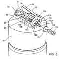
- the pilot valve 80 is shown in more detail in Figure 3 and comprises two aligned semi-cylindrical bodies 91, 92 separated by a gap 93.
- the first body 91 houses a nozzle member 94 having a central body portion 95 the diameter of which is less than that of the bore 96 ( Figure 4) in the body 91 in which it is housed.
- the central body 95 has apertures 97 communicating from its exterior surface to an interior axial passage 98 leading to an orifice 99 at an exposed nozzle end 100 projecting into the gap 93.
- the body 95 has an enlarged threaded head 101 with a slot 102 by means of which the axial position of the nozzle member 94 in the housing 91, and therefore to adjust its position within the gap 93.
- a slidable stem 104 with an enlarged head 105 forming a valve shutter pad engageable against the orifice 99 in the nozzle end 100 of the nozzle member 94.
- the stem 104 is slidable axially of the housing 92 under the action of the lever 68 which, as can be seen in Figure 3, has a bifocated stirrup portion 106 at its pivot end, having two inwardly directed flat fingers 107, 108 which are held against an end face 109 of the housing 92 with the interposition of a washer 110.
- a second washer 111 is held in place on a threaded end 112 of the stem 104 by a pair of lock nuts 113, 114 and the stem 104 is resiliently biased to the left as viewed in Figure 2 by a coil spring 115 which draws the threaded end 112 and, with it, the washer 111 and the lock nuts 113, 114 against the fingers 107, 108 to hold them flat against the washer 110 and to determine the pressure exerted on the nozzle end 100 of the nozzle member 94.
- valve of the invention is fitted to the ends of the hose 20 leading to the life jacket 11 and the line 63 leading to the valve 64 on the air bottle 16.
- valve defined by the valve body 40 and the radial projection 31 is closed by the spring 42
- the valve defined by the enlarged end 52 of the valve member 50 is closed by its engagement with the seal 53
- the servo valve 67 is closed to prevent the flow of air from the axial passage 48.
- the mouthpiece 21 is secured on a suitable mount (not shown) where it is available for use but not in the way of the diver utilising the main mouthpiece 61.
- a first function of the valve of the present invention is to make available the option of a second diver utilising the air supply of the air bottle 16 should any fault in his own air supply develop.
- this depression is transferred to the upper side of the flexible diaphragm 85 which thus flexes upwardly in the middle, being trapped around the periphery by the spacer 86, to lift its surface from the annular array of passages 84 thereby creating a route for air from the chamber 48 between the now upwardly flexed diaphragm 85 and its seat, through the passages 84, along the narrow annular space 82 between the valve body 81 and the cylindrical bore 23, and so through the chamber 25 into the passage 26 of the mouthpiece.
- the calibrated aperture 87 in the flexible diaphragm 85 allows a slow leakage of air from the chamber 48 into the upper chambers 89 and 90 so that this flexible diaphragm 85 will close as the pressure in the chamber 25 rises at the end of inhalation.
- the lever 59 may be depressed to allow air from the gas bottle 16 to be introduced into the lifejacket 11. This causes axial displacement of the end cap 56 and, consequently, the valve stem 51 and enlarged end 52 until the latter is no longer in register with the annular seal 53 in the groove in the valve body 46, whereupon air can communicate through the stem 61 and the axial passage 48, via the transverse passage 44 in the valve casing 22 and into the interior chamber 30 of the spigot 43 which is connected to the hose 20.
- the mouthpiece 21 may be used either by a second diver or by the diver wearing the life jacket 11, either to breathe air from the bottle 16, in parallel with the main mouthpiece 66, or alternatively to breathe air from the life jacket 11 (in which latter case,if there are two divers, the mouthpiece 21 may have to be shared for alternate breaths).
- Buoyancy can be reduced by manual depression of the stem 39, acting on a button 117 at the free end thereof, to open the valve 40 and allow air to pass out through the mouthpiece 29 or, if the diver has the mouthpiece in his mouth, around the edges of the resilient diaphragm 36, thereby controlling the rate of ascent and avoiding the risk of the bends by partially deflating the life jacket.
- the valve also allows the life jacket to be inflated, for example, on the surface, if there is no supply of compressed air available, simply by pressing button 117 on the free end of the shaft 39 hard until the rubber reinforcing disc 38 closes against the shoulder 33 and then blowing into the mouthpiece 29.
Abstract
Description
- The present invention relates generally to an automatic delivery valve, and particularly to a delivery valve adapted for use with a a life jacket.
- Adjustable buoyancy life jackets (ABLJs) have found increasing popularity with both sport and professional divers. Such life jackets can be used to control buoyancy by the selective introduction of air from an air bottle, and this air is not lost when introduced into the life jacket in the sense that it can be withdrawn for emergency breathing if the main breathing air bottle should become exhausted. Such life jackets have a small auxiliary or emergency air bottle, into which air from the main bottle is decanted before a dive, which can be used to inflate the lifejacket from time to time as necessary, and although it contains only a relative small amount of air compared with the main air bottle, this can be critical in determining whether the diver can safely reach the surface in an emergency. In order to make the air from the life jacket available a secondary hose leads from the interior of the life jacket to a secondary mouthpiece held in a clip from which it can be removed to be placed in the diver's mouth when necessary.
- The majority of divers dive in pairs for safety reasons If one diver has difficulty with his air supply it is then possible for the two divers to share the functioning air supply of the other diver whilst ascending to the surface. Conventional techniques for sharing a single mouthpiece have been established, with each diver taking two inhalations and then passing the mouthpiece to the other diver whilst holding his breath for the process to be repeated. This conventional technique has a number of disadvantages; it requires skill and practice to execute, but if the air supply to a diver fails this is very often associated with other problems, and in any case causes stress, a rising pulse and breathing rate and an increased demand for air, which makes sharing a single mouthpiece extremely difficult.
- To overcome this some divers have a secondary mouthpiece connected to a reduction valve on the air bottle for use by their partner in emergencies. This, means that if they also have the above-mentioned subsidiary mouthpiece for an adjustable buoyancy lifejacket, there may be three mouthpieces and hoses on the breathing equipment, and this may be not only cumbersome but also confusing. The present invention seeks therefore to provide a novel valve for breathing apparatus of the like having a single mouthpiece and two inlets, which valve will automatically supply air from one inlet (for example the air bottle) for as long as this is available and then change over to supply air from the other inlet (for example the life jacket) without requiring any action by the user.
- Prior attempts to form such a valve have involved the incorporation of a manually operable control member such as a push button or a lever which had to be operated in synchronism with the breathing. The present invention, on the other hand, provides an entirely automatic breathing valve which requires the diver only to inhale through the mouthpiece in a conventional manner.
- According to the present invention, therefore, there is provided a valve assembly having two inlets, a single outlet and first and second valves controlling the flow of fluid from a respective inlet to the outlet, characterised in that each valve is controlled to open or close by a respective first and second diaphragm, the said first and second diaphragms experiencing substantially the same pressure differential but having a different mechanical resistance from one another so that the first valve opens to allow fluid flow from one inlet to the outlet when the pressure differential reaches a first critical value and the second valve opens to allow fluid flow from the other inlet to the outlet at a second critical value which is higher than the first.
- Preferably the outlet communicates with a common internal chamber to the pressure within which both the first and second diaphragms are exposed on one face.
- In the application specifically described herein the outlet is a mouthpiece for breathing and the first and second inlets are adapted to be connected to primary and secondary sources of breathable gas respectively, although in other embodiments the inlets and outlet may be connected to other sources and destinations and the fluid, the flow of which is controlled by the valve, may be a liquid rather than a gas.
- The present invention also comprehends a life jacket fitted with such a valve assembly. This valve assembly may be used as a secondary mouthpiece for the diver's partner if the partner's air supply should fail, and also may be used as an emergency supply of air from the life jacket if the diver's own air supply should fail. The only difference between inhalation through the secondary mouthpiece when drawing air from the air bottle or the life jacket is the slightly greater force of suction required to create the higher pressure differential between the interior of the valve chamber and the external environment to open the said other valve which is connected to the life jacket interior.
- By utilising two diaphragms having different mechanical resistance values the necessity for any manual controls for breathing is avoided, although a separate manual control lever or button may be provided to allow air to be introduced into the life jacket from the primary air source through the two hoses leading to the mouthpiece, this manual control operating a third valve positioned in the valve housing on the other side of the main valve chamber from the first and second valves so that no air is lost through the mouthpiece when inflating the life jacket.
- Because the secondary mouthpiece will for the majority of the time be clipped to a mount on the life jacket and not be placed in the user's mouth it will itself fill with water and in order to clear it before use the said first valve is preferably provided with a manually operable control member operable to open the first valve to allow air to pass through and clear water from the valve chamber after having been introduced into the user's mouth and prior to inhalation.
- One embodiment of the present invention will now be more particularly described, by way of example, with reference to the accompanying drawings, in which:
- Figure 1 is a perspective view of a life jacket incorporating an automatic delivery valve formed in accordance with the principles of the present invention;
- Figure 2 is a sectional view of a valve formed as an embodiment of the invention;
- Figure 3 is a perspective view of a first detail of the valve shown in Figure 2; and
- Figure 4 is a sectional view of a second detail of the valve shown in Figure 2.
- Referring now to the drawings, the life jacket illustrated in Figure 1, and generally indicated with the
reference numeral 11 comprises two mainlateral buoyancy chambers tubular buoyancy chambers dorsal member 17 which forms a rigid base on which the fabric panels defining the chambers referred to above are held. Attached to thisdorsal member 17, and to the buoyancy chambers areattachment straps - Attached to the upper part of one of the
tubular chambers 15, and in communication with the interior thereof, is aflexible hose 20 which carries at its free end, avalve assembly 21 having amouthpiece 29, formed as an emergency demand valve, as will be described in more detail in relation to Figure 2, and by means of which it is possible for a second diver to breathe air from thebottle 16 or for either diver to breathe the air contained within the life jacket in an emergency. Air can be introduced into the life jacket from an emergency air bottle contained in apocket 90 or from the main air bottle as will be described below. - The main
lateral buoyancy chambers retainers 26 which act to "quilt" thechambers - Referring now to Figure 2 the
valve 21 illustrated is a development of the valve for underwater breathing apparatus described and claimed in our British Patent No 1,339,898, and comprises avalve casing 22, preferably made of injection moulded plastics (although other techniques may be used) in a shape forming two maincylindrical chambers transverse passage 25. Thecasing 22 may be enclosed within an outer cover shown in broken outline in Figure 2, which provides a shaped exterior surface convenient to grip when handling the valve with gloves. In alignment with thetransverse passage 25 is amouthpiece passage 26 defined by atubular spigot 27 having a perimetralannular ridge 28 for retaining amouthpiece 29 of conventional form having a cooperating internal annular groove for receiving theridge 28 and an externalannular groove 10. Themouthpiece 29 is made of a soft elastomeric material sufficiently resilient to be fitted over thespigot 27 andannular ridge 28 and to retain itself thereon with the aid of a retainer band (not shown) fitted into thegroove 10. - The
cylindrical chamber 24 is terminated at one end by an inwardly directedannular projection 31 and at the other end by a cup-shape enlargement 32 comprising a disc-like flat radial wall 33, acylindrical wall 34 and a conically taperedintermediate wall 35 joining the flat radial wall 33 at the base of the cup with thecylindrical wall 34. The cup-shape enlargement 32 houses aresilient diaphragm 36 reinforced on opposite faces by arigid disc 37, on one side and a relativelyhard rubber disc 38 on the other, which also mount thediaphragm 36 to acentral valve shaft 39 which extends from thediaphragm 36 through thecylindrical bore 24 and is connected at its other end to avalve shutter 40 having aconical face 41 which cooperates with the radially inwardly projectingannular ridge 31. Theridge 31 also acts as an abutment for one end of acompression coil spring 42 the other end of which engages against an enlarged end of thecentral valve shaft 39, thereby urging thevalve stem 39 and consequently thevalve 40 axially towards the cup-shape enlargement 32 thereby holding thevalve 40 closed with itsconical face 41 pressed firmly against the annularinward projection 31. - Axially aligned with the
cylindrical bore 24 is acylindrical spigot 30 of similar diameter which is shaped to receive aconnector 47 to thehose 20 leading to thelifejacket 11. - The interior bore of the
spigot 30 communicates via a transverse passageway 44 with a manually controllable valve generally indicated with thereference numeral 45 housed in one end of thebore 23 which extends parallel to thebore 24 in thevalve casing 22. Thevalve 45 comprises avalve body 46 of generally cylindrical form the diameter of which closely matches that of thebore 23 so that it is a sealed fit within it. Thevalve body 46 has anaxial passage 48 and atransverse passage 49 intersecting theaxial passage 48 and aligned with the transverse passage 44 in thevalve body 22 leading to the interior of thespigot 30. - Within the
transverse passage 49 is housed aslide valve member 50 having a narrow central stem 51 and an enlargedhead end 52 which seals within an annular seal 53 housed in an annular groove in thetransverse passage 49. A similarannular seal 54 housed in an annular groove in an enlarged foot end 55 of thevalve slide 50 seals the opposite end thereof in thepassage 49. The foot end 55 has an enlargedcap 56 against which abuts acompression coil spring 57 which surrounds the foot end 55 and passes through anaperture 58 to contact thevalve body 46 at its other end urging thevalve slide member 50 towards the left as viewed in Figure 2 maintaining thelarge head end 52 in contact with the sealing, ring 53 and thereby closing communication between theaxial passage 48 and the transverse passage 44. Alever 59 pivotally mounted at 60 to thevalve body 46 engages thecap 56. On depression of thelever 59 thevalve slide 50 is displaced towards the right as viewed in Figure 2, against the action of thebiasing spring 57, to a position where the enlargedhead end 52 is displaced from the sealing ring 53 to allow communication between theaxial passage 48 and the transverse passage 44 via thetransverse passage 49 and the narrow stem 51 of thevalve member 50. It will be appreciated that the transverse passage 44 in thevalve casing 22 is of slightly greater diameter than thetransverse passage 49 in thevalve body 46 so that the enlargedhead end 52 of thevalve member 50 is received in the former with a sufficient clearance to allow the ready transfer of air. - The
axial passage 48 communicates, via afilter 116, with astem 61 having aconnector 62 to which is connected an air line 63 (Figure 1) leading from acontrol regulator valve 64 of themain air bottle 16. Theregulator valve 64 also supplies anair line 65 to amain mouthpiece 66 for normal use and themouthpiece 21 is provided with a clip or other appropriate housing by which it can be secured against unwanted movement when not in use. - The inner end of the
axial passage 48 in thevalve body 46, that is the end facing inwardly of theaxial bore 23 in thecasing 22 is closed by aservo valve 67 having apilot valve 80 with acontrol lever 68 the end of which is engaged against theinner end 69 of astem 70 carried by arolling diaphragm 71 within a diaphragm chamber generally indicated 72 having oppositeradial walls 73, 74 with respective apertures 75, 76. Each of theradial walls 73, 74 has a respective peripheralaxial flange diaphragm 71 between them. Thestem 70 is guided in respective central apertures in theradial walls 73, 74 and afree end 79 thereof projects from thediaphragm chamber 72 in order to act as a push button which can be pressed to cause axial displacement of thestem 70, guided by the central apertures in theradial walls 73, 74 causing thelever 68 to depress and open thepilot valve 80 of theservo valve 67 as will be described below. Axial displacement of thestem 70 may also be caused by a pressure differential across thediaphragm 71. - The
servo valve 67 comprises an inverted cup-shape body 81 (Figure 4) fitted over the upper end of thecylindrical valve body 46 housing the manuallyoperable valve 45. The cup-shape body 81 has an outer diameter which is less than the inner diameter of thebore 23 so as to leave anannular passage way 82 between them, and the open end of the inverted cup-shape body 81 fits over aradial flange 83 havingaxial apertures 84 the upper ends of which are closed by the periphery of aresilient disc 85 clamped between theflange 83 and an apertured spacer disc 86 lodged between the perimeter of thedisc 85 and a shoulder on the inner wall of the inverted cup-shape valve body 81. Theresilient disc 85 has a calibratedcentral aperture 87 whilst the spacer 86 has a plurality ofapertures 88 allowing communication between anupper chamber 89 within the inverted cup-shape valve body 81 and anintermediate chamber 90 between the spacer disc 86 and theresilient valve disc 85. - The
pilot valve 80 is shown in more detail in Figure 3 and comprises two alignedsemi-cylindrical bodies gap 93. Thefirst body 91 houses anozzle member 94 having acentral body portion 95 the diameter of which is less than that of the bore 96 (Figure 4) in thebody 91 in which it is housed. Thecentral body 95 hasapertures 97 communicating from its exterior surface to an interioraxial passage 98 leading to anorifice 99 at an exposed nozzle end 100 projecting into thegap 93. At the opposite end thebody 95 has an enlarged threaded head 101 with aslot 102 by means of which the axial position of thenozzle member 94 in thehousing 91, and therefore to adjust its position within thegap 93. - Within the axially aligned
housing 92 there is aslidable stem 104 with anenlarged head 105 forming a valve shutter pad engageable against theorifice 99 in the nozzle end 100 of thenozzle member 94. Thestem 104 is slidable axially of thehousing 92 under the action of thelever 68 which, as can be seen in Figure 3, has abifocated stirrup portion 106 at its pivot end, having two inwardly directedflat fingers end face 109 of thehousing 92 with the interposition of awasher 110. Asecond washer 111 is held in place on a threadedend 112 of thestem 104 by a pair oflock nuts stem 104 is resiliently biased to the left as viewed in Figure 2 by acoil spring 115 which draws the threadedend 112 and, with it, thewasher 111 and thelock nuts fingers washer 110 and to determine the pressure exerted on the nozzle end 100 of thenozzle member 94. By suitably adjusting thehead end 103 of the nozzle member by engaging a suitable tool in theslot 102, and by correspondingly adjusting thelock nuts orifice 99 and the pressure exerted on it by theshutter head 105 for purposes which will be described in more detail hereinbelow. - In use, the valve of the invention is fitted to the ends of the
hose 20 leading to thelife jacket 11 and theline 63 leading to thevalve 64 on theair bottle 16. Normally, the valve defined by thevalve body 40 and theradial projection 31 is closed by thespring 42, the valve defined by theenlarged end 52 of thevalve member 50 is closed by its engagement with the seal 53 and theservo valve 67 is closed to prevent the flow of air from theaxial passage 48. Themouthpiece 21 is secured on a suitable mount (not shown) where it is available for use but not in the way of the diver utilising themain mouthpiece 61. A first function of the valve of the present invention is to make available the option of a second diver utilising the air supply of theair bottle 16 should any fault in his own air supply develop. For this purpose it is simply necessary to take themouthpiece 21, clear the water from it as will be described, insert thetooth grip 29 in the conventional manner and inhale. Such inhalation will cause a vacuum in thetransverse passage 25 and therefore a pressure differential across both thediaphragm 36 in the cup-shape enlargement 32 and thediaphragm 71 in thediaphragm chamber 72. Thespring 42 initially resists displacement of thediaphragm 36 up to and above a pressure differential which causes thediaphragm 71 to flex, thereby displacing thepin 70 to depress thelever 68 which results in theflat fingers stem 104 and thus theshutterhead 105 away from thenozzle orifice 99. This opens communication between thechamber 25 and thechamber 48 through a pathway comprising thenozzle orifice 99, the interior of the nozzle body, theradial passages 97, the communicatingpassage 83, thechamber 89, thepassages 88 in the spacer 86, thegap 90 and the calibratedorifice 87 in theflexible diaphragm 85. Because, during inhalation, the pressure in thechamber 25 is maintained low this depression is transferred to the upper side of theflexible diaphragm 85 which thus flexes upwardly in the middle, being trapped around the periphery by the spacer 86, to lift its surface from the annular array ofpassages 84 thereby creating a route for air from thechamber 48 between the now upwardly flexeddiaphragm 85 and its seat, through thepassages 84, along the narrowannular space 82 between thevalve body 81 and thecylindrical bore 23, and so through thechamber 25 into thepassage 26 of the mouthpiece. The calibratedaperture 87 in theflexible diaphragm 85 allows a slow leakage of air from thechamber 48 into theupper chambers flexible diaphragm 85 will close as the pressure in thechamber 25 rises at the end of inhalation. - Upon exhalation the increase in pressure causes the
servo valve 67 to close and, because it is restrained by thevalve stem 39, thediaphragm 36 in the cup-shape body 32 allows the escape of air around its periphery. - Whether or not the
mouthpiece 21 is being used for breathing by the second diver, thelever 59 may be depressed to allow air from thegas bottle 16 to be introduced into thelifejacket 11. This causes axial displacement of theend cap 56 and, consequently, the valve stem 51 andenlarged end 52 until the latter is no longer in register with the annular seal 53 in the groove in thevalve body 46, whereupon air can communicate through thestem 61 and theaxial passage 48, via the transverse passage 44 in thevalve casing 22 and into theinterior chamber 30 of thespigot 43 which is connected to thehose 20. Any air so transferred into the lifejacket is not lost for breathing, however, since should thegas bottle 16 become exhausted before the diver has reached the surface, it is nevertheless possible to breathe the gas in the life jacket, again by inhaling through themouthpiece 21 after theteeth grip 29 has been placed in the mouth. Additional air can be introduced directly into the life jacket from the small emergency cylinder to replace that withdrawn if necessary to maintain buoyancy. In these circumstances, since a reduction in the pressure within thechamber 25 cannot cause opening of the valve 67 (since the gas bottle 16) is assumed to be completely exhausted) and consequently even though thediaphragm 71 may be displaced by the pressure differential between the interior of thechamber 25 and the surrounding environment, theservo valve 67 will not open because there is inadequate pressure differential across theflexible diaphragm 85. - This results in a further fall in the pressure in the
chamber 25 sufficient to overcome the resistance of thespring 42 by the force exerted by the pressure differential across thediaphragm 36 and this therefore urges the valve stem 39 downwardly as viewed in Figure 2 opening thevalve 40 and allowing air to enter the mouthpiece from thelifejacket 11. Displacement of thevalve stem 39 causes thediaphragm 36 to move into the region of the cup-shape enlargement 34 constituted by the conically taperedwalls 35 thereby increasing the security of the seal and ensuring no water enters thorugh this valve. Upon exhalation thestem 39 moves axially until thevalve 40 closes and expired air again passes around the perimeter of thediaphragm 36. - In an emergency, therefore, the
mouthpiece 21 may be used either by a second diver or by the diver wearing thelife jacket 11, either to breathe air from thebottle 16, in parallel with themain mouthpiece 66, or alternatively to breathe air from the life jacket 11 (in which latter case,if there are two divers, themouthpiece 21 may have to be shared for alternate breaths). - During an ascent the air in the life jacket expands and, because of the reduction in pressure, increased buoyancy may lead to a too-rapid rise. Buoyancy can be reduced by manual depression of the
stem 39, acting on abutton 117 at the free end thereof, to open thevalve 40 and allow air to pass out through themouthpiece 29 or, if the diver has the mouthpiece in his mouth, around the edges of theresilient diaphragm 36, thereby controlling the rate of ascent and avoiding the risk of the bends by partially deflating the life jacket. - The valve also allows the life jacket to be inflated, for example, on the surface, if there is no supply of compressed air available, simply by pressing
button 117 on the free end of theshaft 39 hard until therubber reinforcing disc 38 closes against the shoulder 33 and then blowing into themouthpiece 29.
Claims (11)
Priority Applications (1)
| Application Number | Priority Date | Filing Date | Title |
|---|---|---|---|
| AT88310169T ATE85010T1 (en) | 1987-10-28 | 1988-10-28 | AUTOMATIC FEED VALVE. |
Applications Claiming Priority (2)
| Application Number | Priority Date | Filing Date | Title |
|---|---|---|---|
| GB8725208 | 1987-10-28 | ||
| GB878725208A GB8725208D0 (en) | 1987-10-28 | 1987-10-28 | Automatic delivery valve |
Publications (2)
| Publication Number | Publication Date |
|---|---|
| EP0318157A1 true EP0318157A1 (en) | 1989-05-31 |
| EP0318157B1 EP0318157B1 (en) | 1993-01-27 |
Family
ID=10626015
Family Applications (1)
| Application Number | Title | Priority Date | Filing Date |
|---|---|---|---|
| EP88310169A Expired - Lifetime EP0318157B1 (en) | 1987-10-28 | 1988-10-28 | An automatic delivery valve |
Country Status (5)
| Country | Link |
|---|---|
| EP (1) | EP0318157B1 (en) |
| AT (1) | ATE85010T1 (en) |
| DE (1) | DE3877915T2 (en) |
| ES (1) | ES2037237T3 (en) |
| GB (1) | GB8725208D0 (en) |
Cited By (4)
| Publication number | Priority date | Publication date | Assignee | Title |
|---|---|---|---|---|
| EP0615899A2 (en) * | 1993-03-15 | 1994-09-21 | Stephen Allan Craske | Scuba breathing apparatus |
| WO1996018535A2 (en) * | 1994-12-12 | 1996-06-20 | Diving Unlimited International | Buoyancy compensator assembly |
| WO1999013944A1 (en) | 1997-09-18 | 1999-03-25 | A P Valves | Self-contained breathing apparatus |
| WO2001002246A1 (en) * | 1999-06-30 | 2001-01-11 | Scubapro Europe S.R.L. | Balancing jacket for divers |
Citations (4)
| Publication number | Priority date | Publication date | Assignee | Title |
|---|---|---|---|---|
| US3219034A (en) * | 1962-07-31 | 1965-11-23 | Kalenik Ladimur | Underwater breathing apparatus |
| US3898705A (en) * | 1974-09-13 | 1975-08-12 | Pittman Products Inc | Convertible inflation control for underwater diving vests |
| GB2084881A (en) * | 1980-09-24 | 1982-04-21 | Hardy George Brian | Breathing device |
| WO1987006557A1 (en) * | 1986-04-21 | 1987-11-05 | Buoyco (Divers) Limited | Venting valve apparatus |
-
1987
- 1987-10-28 GB GB878725208A patent/GB8725208D0/en active Pending
-
1988
- 1988-10-28 DE DE8888310169T patent/DE3877915T2/en not_active Expired - Fee Related
- 1988-10-28 AT AT88310169T patent/ATE85010T1/en not_active IP Right Cessation
- 1988-10-28 ES ES198888310169T patent/ES2037237T3/en not_active Expired - Lifetime
- 1988-10-28 EP EP88310169A patent/EP0318157B1/en not_active Expired - Lifetime
Patent Citations (4)
| Publication number | Priority date | Publication date | Assignee | Title |
|---|---|---|---|---|
| US3219034A (en) * | 1962-07-31 | 1965-11-23 | Kalenik Ladimur | Underwater breathing apparatus |
| US3898705A (en) * | 1974-09-13 | 1975-08-12 | Pittman Products Inc | Convertible inflation control for underwater diving vests |
| GB2084881A (en) * | 1980-09-24 | 1982-04-21 | Hardy George Brian | Breathing device |
| WO1987006557A1 (en) * | 1986-04-21 | 1987-11-05 | Buoyco (Divers) Limited | Venting valve apparatus |
Cited By (9)
| Publication number | Priority date | Publication date | Assignee | Title |
|---|---|---|---|---|
| EP0615899A2 (en) * | 1993-03-15 | 1994-09-21 | Stephen Allan Craske | Scuba breathing apparatus |
| EP0615899A3 (en) * | 1993-03-15 | 1994-11-17 | Stephen Allan Craske | Scuba breathing apparatus. |
| WO1996018535A2 (en) * | 1994-12-12 | 1996-06-20 | Diving Unlimited International | Buoyancy compensator assembly |
| US5620282A (en) * | 1994-12-12 | 1997-04-15 | Diving Unlimited International | Buoyancy compensator assembly |
| WO1996018535A3 (en) * | 1994-12-12 | 2001-12-20 | Diving Unltd Internat | Buoyancy compensator assembly |
| WO1999013944A1 (en) | 1997-09-18 | 1999-03-25 | A P Valves | Self-contained breathing apparatus |
| US6712071B1 (en) | 1997-09-18 | 2004-03-30 | Martin John Parker | Self-contained breathing apparatus |
| WO2001002246A1 (en) * | 1999-06-30 | 2001-01-11 | Scubapro Europe S.R.L. | Balancing jacket for divers |
| US6461080B1 (en) * | 1999-06-30 | 2002-10-08 | Scubapro Europe S.R.L. | Balancing jacket for divers |
Also Published As
| Publication number | Publication date |
|---|---|
| ES2037237T3 (en) | 1993-06-16 |
| ATE85010T1 (en) | 1993-02-15 |
| DE3877915T2 (en) | 1993-06-09 |
| GB8725208D0 (en) | 1987-12-02 |
| DE3877915D1 (en) | 1993-03-11 |
| EP0318157B1 (en) | 1993-01-27 |
Similar Documents
| Publication | Publication Date | Title |
|---|---|---|
| EP1512426B1 (en) | Exhalation valve | |
| US4239038A (en) | Manual resuscitators | |
| US4606340A (en) | Combined pressure compensating exhalation and anti-suffocation valve | |
| US4996982A (en) | Emergency breathing apparatus with holster released regulator valve | |
| US4573463A (en) | Breathing mask | |
| US4068657A (en) | Constant volume buoyancy compensation system | |
| US3866253A (en) | Divers buoyancy vest | |
| US4227521A (en) | Air system for scuba diving | |
| GB2044110A (en) | Respiratory mask | |
| EP0278598B1 (en) | Scuba breathing apparatus | |
| AU2020231147B2 (en) | Diving mask with pressure-balancing means | |
| US5645047A (en) | Inhalation mask | |
| US4211220A (en) | Diving helmet assembly | |
| US3138155A (en) | Underwater swimming and diving suits | |
| EP0021803B1 (en) | Valves and breathing apparatus incorporating such valves | |
| US8235038B2 (en) | Scuba mask purging apparatus and method | |
| EP0318157B1 (en) | An automatic delivery valve | |
| US3570808A (en) | Coupling assembly for underwater face mask | |
| US4503852A (en) | Pilot controlled regulator second stage | |
| EP0143618A2 (en) | Exhalation valve | |
| US3938511A (en) | Mouthpiece regulator for an underwater breathing apparatus | |
| US3143739A (en) | Face mask for divers | |
| EP0615899A2 (en) | Scuba breathing apparatus | |
| EP1631356A2 (en) | Expiratory valve unit | |
| GB2209123A (en) | Breathing apparatus |
Legal Events
| Date | Code | Title | Description |
|---|---|---|---|
| PUAI | Public reference made under article 153(3) epc to a published international application that has entered the european phase |
Free format text: ORIGINAL CODE: 0009012 |
|
| AK | Designated contracting states |
Kind code of ref document: A1 Designated state(s): AT BE CH DE ES FR GB GR IT LI NL SE |
|
| 17P | Request for examination filed |
Effective date: 19890825 |
|
| 17Q | First examination report despatched |
Effective date: 19901128 |
|
| GRAA | (expected) grant |
Free format text: ORIGINAL CODE: 0009210 |
|
| AK | Designated contracting states |
Kind code of ref document: B1 Designated state(s): AT BE CH DE ES FR GB GR IT LI NL SE |
|
| PG25 | Lapsed in a contracting state [announced via postgrant information from national office to epo] |
Ref country code: CH Effective date: 19930127 Ref country code: GR Free format text: LAPSE BECAUSE OF FAILURE TO SUBMIT A TRANSLATION OF THE DESCRIPTION OR TO PAY THE FEE WITHIN THE PRESCRIBED TIME-LIMIT Effective date: 19930127 Ref country code: LI Effective date: 19930127 Ref country code: BE Effective date: 19930127 Ref country code: AT Effective date: 19930127 |
|
| REF | Corresponds to: |
Ref document number: 85010 Country of ref document: AT Date of ref document: 19930215 Kind code of ref document: T |
|
| REF | Corresponds to: |
Ref document number: 3877915 Country of ref document: DE Date of ref document: 19930311 |
|
| ET | Fr: translation filed | ||
| ITF | It: translation for a ep patent filed |
Owner name: SOCIETA' ITALIANA BREVETTI S.P.A. |
|
| REG | Reference to a national code |
Ref country code: CH Ref legal event code: PL |
|
| REG | Reference to a national code |
Ref country code: ES Ref legal event code: FG2A Ref document number: 2037237 Country of ref document: ES Kind code of ref document: T3 |
|
| PLBE | No opposition filed within time limit |
Free format text: ORIGINAL CODE: 0009261 |
|
| STAA | Information on the status of an ep patent application or granted ep patent |
Free format text: STATUS: NO OPPOSITION FILED WITHIN TIME LIMIT |
|
| 26N | No opposition filed | ||
| EAL | Se: european patent in force in sweden |
Ref document number: 88310169.3 |
|
| PGFP | Annual fee paid to national office [announced via postgrant information from national office to epo] |
Ref country code: NL Payment date: 19971030 Year of fee payment: 10 |
|
| PG25 | Lapsed in a contracting state [announced via postgrant information from national office to epo] |
Ref country code: NL Free format text: LAPSE BECAUSE OF NON-PAYMENT OF DUE FEES Effective date: 19990501 |
|
| NLV4 | Nl: lapsed or anulled due to non-payment of the annual fee |
Effective date: 19990501 |
|
| PGFP | Annual fee paid to national office [announced via postgrant information from national office to epo] |
Ref country code: SE Payment date: 20001031 Year of fee payment: 13 |
|
| PGFP | Annual fee paid to national office [announced via postgrant information from national office to epo] |
Ref country code: ES Payment date: 20001229 Year of fee payment: 13 |
|
| REG | Reference to a national code |
Ref country code: GB Ref legal event code: 711B |
|
| REG | Reference to a national code |
Ref country code: GB Ref legal event code: 711G |
|
| PG25 | Lapsed in a contracting state [announced via postgrant information from national office to epo] |
Ref country code: SE Free format text: LAPSE BECAUSE OF NON-PAYMENT OF DUE FEES Effective date: 20011029 Ref country code: ES Free format text: LAPSE BECAUSE OF NON-PAYMENT OF DUE FEES Effective date: 20011029 |
|
| REG | Reference to a national code |
Ref country code: GB Ref legal event code: IF02 |
|
| EUG | Se: european patent has lapsed |
Ref document number: 88310169.3 |
|
| PGFP | Annual fee paid to national office [announced via postgrant information from national office to epo] |
Ref country code: FR Payment date: 20021017 Year of fee payment: 15 |
|
| PGFP | Annual fee paid to national office [announced via postgrant information from national office to epo] |
Ref country code: DE Payment date: 20021218 Year of fee payment: 15 |
|
| REG | Reference to a national code |
Ref country code: ES Ref legal event code: FD2A Effective date: 20021113 |
|
| PG25 | Lapsed in a contracting state [announced via postgrant information from national office to epo] |
Ref country code: DE Free format text: LAPSE BECAUSE OF NON-PAYMENT OF DUE FEES Effective date: 20040501 |
|
| PG25 | Lapsed in a contracting state [announced via postgrant information from national office to epo] |
Ref country code: FR Free format text: LAPSE BECAUSE OF NON-PAYMENT OF DUE FEES Effective date: 20040630 |
|
| REG | Reference to a national code |
Ref country code: FR Ref legal event code: ST |
|
| PG25 | Lapsed in a contracting state [announced via postgrant information from national office to epo] |
Ref country code: IT Free format text: LAPSE BECAUSE OF NON-PAYMENT OF DUE FEES;WARNING: LAPSES OF ITALIAN PATENTS WITH EFFECTIVE DATE BEFORE 2007 MAY HAVE OCCURRED AT ANY TIME BEFORE 2007. THE CORRECT EFFECTIVE DATE MAY BE DIFFERENT FROM THE ONE RECORDED. Effective date: 20051028 |
|
| PGFP | Annual fee paid to national office [announced via postgrant information from national office to epo] |
Ref country code: GB Payment date: 20071005 Year of fee payment: 20 |
|
| REG | Reference to a national code |
Ref country code: GB Ref legal event code: 732E |
|
| REG | Reference to a national code |
Ref country code: GB Ref legal event code: PE20 Expiry date: 20081027 |
|
| PG25 | Lapsed in a contracting state [announced via postgrant information from national office to epo] |
Ref country code: GB Free format text: LAPSE BECAUSE OF EXPIRATION OF PROTECTION Effective date: 20081027 |