EP0313977A2 - Holder for reagent tubes, sample tube and the like - Google Patents
Holder for reagent tubes, sample tube and the like Download PDFInfo
- Publication number
- EP0313977A2 EP0313977A2 EP88117427A EP88117427A EP0313977A2 EP 0313977 A2 EP0313977 A2 EP 0313977A2 EP 88117427 A EP88117427 A EP 88117427A EP 88117427 A EP88117427 A EP 88117427A EP 0313977 A2 EP0313977 A2 EP 0313977A2
- Authority
- EP
- European Patent Office
- Prior art keywords
- block
- clamping
- groove
- side surfaces
- adjusting unit
- Prior art date
- Legal status (The legal status is an assumption and is not a legal conclusion. Google has not performed a legal analysis and makes no representation as to the accuracy of the status listed.)
- Withdrawn
Links
Images

Classifications
-
- B—PERFORMING OPERATIONS; TRANSPORTING
- B01—PHYSICAL OR CHEMICAL PROCESSES OR APPARATUS IN GENERAL
- B01L—CHEMICAL OR PHYSICAL LABORATORY APPARATUS FOR GENERAL USE
- B01L9/00—Supporting devices; Holding devices
- B01L9/04—Retort stands; Retort clamps
Landscapes
- Health & Medical Sciences (AREA)
- Clinical Laboratory Science (AREA)
- Chemical & Material Sciences (AREA)
- Chemical Kinetics & Catalysis (AREA)
- Automatic Analysis And Handling Materials Therefor (AREA)
- Devices For Use In Laboratory Experiments (AREA)
Abstract
Description
Die Erfindung betrifft eine Stelleinheit für Reagenz-, Probenröhrchen o.dgl., gebildet durch einen Block oder Zylinder mit einer oben offenen Ausnehmung.The invention relates to an actuating unit for reagent, sample tubes or the like, formed by a block or cylinder with a recess open at the top.
Derartige bekannte Stelleinheiten, in der Regel aus Holz, Metall oder Kunststoff enthalten mehrere Ausnehmungen. Sie stehen auf den Labortischen. Die Person, die mit dem Inhalt von Reagenz-, Probenröhrchen o.dgl. Tests durchführt, entnimmt daraus die Röhrchen und stellt sie nach einer bestimmten Handhabung wieder in die Stelleinheit zurück.Such known actuators, usually made of wood, metal or plastic, contain several recesses. They are on the laboratory tables. The person who or the like with the contents of reagent, sample tubes. Carries out tests, takes the tubes from them and puts them back into the actuating unit after a certain handling.
Das Füllen der Röhrchen durch eine Blutprobe o.dgl., die einem Patienten entnommen wird, erfolgt in einer Klinik oder einer Artzpraxis. Von dort wird das Röhrchen dann an ein Labor weitergegeben. Im Labor werden die Analysen gemacht. Bei all diesen Vorgängen dienen die Stelleinheiten, die in der Regel 10 bis 12 Ausnehmungen aufweisen, zur Halterung der Reagenz-, bzw. Probenröhrchen in aufrechter Lage. Doch sind diese bekannten Stelleinheiten zum Transport ungeeignet. Vor der Handhabung werden die Röhrchen bisher irgendeiner Transportpackung entnommen und dann ggf. in den Stelleinheiten abgestellt; die Weitergabe erfolgt bisher ohne besondere Einrichtungen, die in einfacher Weise Verpackung und Ordnung ersetzten könnten.The tubes are filled by a blood sample or the like, which is taken from a patient, in a clinic or doctor's office. From there, the tube is passed on to a laboratory. The analyzes are done in the laboratory. In all of these processes, the adjusting units, which generally have 10 to 12 recesses, serve to hold the reagent or sample tubes in an upright position. However, these known control units are unsuitable for transportation. Before handling, the tubes have so far been removed from some transport packaging and then possibly placed in the positioning units; The transfer has so far been carried out without special facilities that could easily replace packaging and order.
Der Erfindung liegt demgegenüber die Aufgabe zugrunde, eine Stelleinheit zu schaffen, die universell mit anderen Stelleinheiten derart kombiniert werden kann, daß die Röhrchen, die einem bestimmten Patienten oder einer bestimmten Arztpraxis zuordenbar sind (und deren Zahl je nach Art und Weise bzw. Umfang der Tests variieren können), zu einem aus entsprechend vielen Stelleinheiten zusammengefügten Verbund zusammengebracht werden können, der während der gesamten Handhabung von der Blutentnahme am Patienten bis zum Abschluß des Tests derselbe bleibt. Auf diese Art sollen Verwechslungen, die Notwendigkeit eines Umsteckens eines Röhrchens von einer Stelleinheit in eine andere vermieden werden. In anderen Worten: Es soll ein einfaches variables Organisationsmittel für Kliniken und Arztpraxen zur Handhabung von Reagenz- und Probenröhrchen geschaffen werden.The invention is based on the object to provide an actuating unit that can be combined universally with other actuating units such that the tubes that can be assigned to a specific patient or a specific medical practice (and their number depending on the type and scope of the Tests can vary), can be brought together to form an assembly composed of a correspondingly large number of actuating units, which remains the same throughout the entire procedure from the drawing of blood to the patient until the end of the test. This is to avoid confusion and the need to move a tube from one actuator to another. In other words, it's supposed to be a simple variable Organizational means for clinics and medical practices for handling reagent and sample tubes are created.
Diese Aufgabe wird erfindungsgemäß dadurch gelöst, daß die Seitenflächen des eine Stelleinheit bildenden Blocks oder Zylinders mit sich senkrecht zu dieser Fläche erstreckenden Klemmöffnungen und sich ebenfalls senkrecht zu dieser Seitenfläche erstreckenden Klemmvorsprüngen vorgesehen sind.This object is achieved in that the side surfaces of the block or cylinder forming an actuating unit are provided with clamping openings extending perpendicularly to this surface and also clamping projections extending perpendicularly to this side surface.
Die Ausbildung von Klemmöffnungen und Klemmvorsprüngen mit senkrecht zu den Seitenflächen des Blocks oder Zylinders sich erstreckenden Flächen gewährleistet, daß mehrere Stelleinheiten in beliebiger Zahl und in allen Richtungen der waagerechten Ebene zu einem Verbund zusammengefügt werden können, wobei das Zusammenfügen durch Einschieben bzw. Herausziehen senkrecht zu den Seitenflächen des quaderförmigen Blocks erfolgen kann. Es kann somit in x- bzw. y-Richtung auf einer Stellfläche, auf dem der gesamte durch eine Vielzahl von Stelleinheiten entstehende Verbund steht, erfolgen. Dadurch kann man beim Zusammenstecken der Stelleinheiten und beim Auseinanderziehen jeweils die Fläche eines Tisches o.dg. als Stützfläche benutzen, so daß bei der Handhabung, insbesondere bei Überwindung der Klemmkraft, eine sichere Führung möglich wird, so daß eine Verschütten oder ein Abrutschen der Hand vermieden wird. Auf diese Weise kann durch Zusammenfügen einer beliebiger Zahl von Stelleinheiten ein Verbund hergestellt werden, der exakt soviel Ausnehmungen aufweist, wie man für die Proben eines Patienten oder einer Patientengruppe braucht. Derselbe Verbund kann bereits von dem Arzt, der die Probe entnimmt, entsprechend der benötigten Zahl von Ausnehmungen für Reagenz- oder Probenröhrchen zusammengestellt werden. Dieser Verbund wird dann zum Labor transportiert und dort während der gesamten Tests verwendet Durch die Steckbarkeit in beiden Richtungen (x- u. y-Richtung) in der waagerechten Ebene unterscheidet sich die Erfindung von irgendwelchen schwalbenschwanzförmigen Steckverbindungen, die ein Ineinanderstecken nur in vertikaler Richtung ermöglichen, was umständlicher ist.The formation of clamping openings and clamping projections with surfaces extending perpendicular to the side surfaces of the block or cylinder ensures that several actuating units in any number and in all directions of the horizontal plane can be joined to form a composite, the joining by pushing in or pulling out vertically the side surfaces of the cuboid block can take place. It can thus take place in the x or y direction on a footprint on which the entire composite resulting from a large number of actuating units is located. This allows you to put the surface of a table or the like when plugging the actuating units and pulling them apart. use as a support surface so that safe handling is possible when handling, especially when overcoming the clamping force, so that spilling or slipping of the hand is avoided. In this way, by combining any number of actuating units, a composite can be produced which has exactly as many recesses as one can for needs samples from a patient or group of patients. The same combination can already be put together by the doctor taking the sample according to the required number of recesses for reagent or sample tubes. This composite is then transported to the laboratory and used there during the entire test. Due to the pluggability in both directions (x- and y-direction) in the horizontal plane, the invention differs from any dovetail-shaped plug connections that only allow one to plug into the other in the vertical direction which is more cumbersome.
Eine vorteilhafte Weiterbildung der Erfindung sieht vor, daß die Klemmöffnungen durch eine senkrecht verlaufende Nut, deren Seitenflächen senkrecht zur Seitenfläche des quaderförmigen Blocks verlaufen und die Klemmvorsprünge durch mindestens eine parallel zu der genannten Nut verlaufende Feder, deren Seitenflächen ebenfalls senkrecht zur Seitenfläche des quaderförmigen Blocks verlaufen, gebildet werden. Damit entstehen Nut/Feder-Verbindungen.An advantageous development of the invention provides that the clamping openings through a perpendicular groove, the side surfaces of which run perpendicular to the side surface of the rectangular block, and the clamping projections through at least one spring running parallel to the said groove, the side surfaces of which likewise run perpendicular to the side surface of the rectangular block , are formed. This creates tongue and groove connections.
Vorteilhafter Weise ist bei einer derartigen Nut/Feder-Verbindung vorgesehen, daß nicht nur eine Feder, sondern zwei zueinander parallele und gegeneinander unter Klemmdruck zusammenpreßbare Federn vorgesehen sind, deren einander abgewandte Außenflächen voneinander einen Abstand haben, der geringfügig gröber als die Breite der Nut ist. Beim Zusammenstecken werden also die beiden Stege federend gegeneinander etwas zusammengepreßt. Der Rückdruck ist dann der Klemmdruck. Diese beim Vorsehen von zwei Stegen gegebene Möglichkeit der elastischen Verformung zur Erzeugung des Klemmdrucks sichert eine lange Lebensdauer bei gleichbleibendem Klemmdruck. Ferner können damit Fertigungstoleranzen etc. ausgeglichen werden.In such a tongue and groove connection, it is advantageously provided that not only one tongue, but two springs parallel to one another and compressible against one another under clamping pressure are provided, the mutually facing outer surfaces of which are at a distance from one another which is slightly coarser than the width of the groove . At the Put together the two webs are resiliently pressed together somewhat. The back pressure is then the clamping pressure. This possibility of elastic deformation to generate the clamping pressure, which is provided when two webs are provided, ensures a long service life with the clamping pressure remaining the same. Furthermore, manufacturing tolerances etc. can be compensated for.
Vorteilhafterweise ist dabei vorgesehen, daß der Abstand der einen Ecke des Blocks von der nächsten Feder gleich dem Abstand benachbarten Ecke von der Nut ist. Auf diese Weise passen in jeder möglichen Stellung der Stelleinheiten zueinander jeweils eine Nut und zwei gegenüberliegende Federn zur Bildung einer Klemmverbindung zusammen. Es entstehen pro Seitenfläche 2 parallele Nuten/Federverbindungen, die eine optimale Klemmung gleichzeitig mit universaler Verwendbarkeit sichern.It is advantageously provided that the distance of one corner of the block from the next tongue is equal to the distance between the adjacent corner and the groove. In this way, in each possible position of the actuating units, a groove and two opposite tongues fit together to form a clamp connection. There are 2 parallel grooves / tongue connections per side surface, which ensure optimal clamping at the same time with universal usability.
Eine weitere vorteilhafte Weiterbildung der Erfindung sieht vor, daß auf der Unterseite des quaderförmigen Blocks eine Klemmöffnung vorgesehen ist, die zum Eingriff eines Klemmvorsprungs in einer Stellplatte geeignet ist.A further advantageous development of the invention provides that a clamping opening is provided on the underside of the cuboid block, which is suitable for engaging a clamping projection in a setting plate.
Eine solche Stellplatte kann dann z.B. in einer Wanne oder auf einem Labortisch oder der Ladefläche in einem Transportwagen angebracht sein, so daß - nach dem Festklemmen des Verbundes - ein sicherer Transport erfolgen kann, ohne daß die Gefahr besteht, daß eine Stelleinheit oder ein Verbund aus nur wenigen Stelleinheiten umkippt oder verrutscht.Such a positioning plate can then be attached, for example, in a tub or on a laboratory table or the loading area in a transport trolley, so that - after the assembly has been clamped in place - safe transport can take place without the risk there is that an actuating unit or a composite of only a few actuating units topples or slips.
Insgesamt entsteht ein universell verwendebares äußerst einfaches Organisationsgerät für Arztpraxen und/oder Kliniken. Vorzugsweise ist das Material ABS-Kunststoff und die Stelleinheit als Hohlkörper ausgebildet, um Material zu sparen.Overall, a universally usable, extremely simple organizational device for doctor's practices and / or clinics is created. The ABS plastic material and the actuating unit are preferably designed as hollow bodies in order to save material.
Ein Ausführungsbeispiel der Erfindung und ihrer vorteilhaften Weiterbildungen wird im folgenden anhand der beigefügten Zeichnungen beschrieben. Es stellen dar:
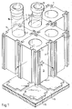
Figur 1 ein Verbund aus mehreren Stelleinheiten mit zwei Reagenzröhrchen,Figur 2 eine Draufsicht auf zwei miteinander zu einem Verbund zusammengesteckte Stelleinheiten,Figur 3 eine Ansicht von unten von zwei miteinander zu einem Verbund verbundenen Stelleinheiten,- Figur 4 einen Schnitt entlang der Linie IV-IV in Fig. 2.
- FIG. 1 shows a combination of several control units with two test tubes,
- FIG. 2 shows a plan view of two actuating units which are plugged together to form a composite,
- FIG. 3 shows a view from below of two adjusting units connected to one another to form a composite,
- FIG. 4 shows a section along the line IV-IV in FIG. 2.
Figur 1 zeigt einen Verbund aus fünf Stelleinheiten, die je durch einen quaderförmigen Block 1 gebildet werden. Auf seiner oberen Stirnseite ist jeder Block 1 je mit einer Ausnehmung 2 versehen. In zwei der gezeigten Ausnehmungen stecken Reagenzröhrchen 10. Diese Ausnehmungen 2 sind, wie aus Fig. 4 ersichtlich, im wesentlichen zylindrisch mit einem gerundetem Boden.FIG. 1 shows a combination of five actuating units, each of which is formed by a
Wie am besten aus Fig. 1, und zwar beim Block 1 in der Bildmitte vorne, sowie ferner aus Fig. 2 ersichtlich ist, weist jede Seitenfläche 3 eine Nut 4 und zwei zum Verlauf der Nut parallele Stege 6 und 7 auf. Die Seitenflächen 4′, 4˝ der Nut 4, sowie die Seitenflächen 6′, 6˝, 7′, 7˝ der Stege 6, 7 verlaufen senkrecht zur Seitenfläche 3 und zueinander sowie zu den angrenzenden Seitenflächen parallel. Auf diese Weise sind die Stelleinheiten, jeweils gebildet durch einen Block 1 in der beschriebenen Ausbildung, sowohl in x- als auch in y-Richtung (vgl. Fig. 1, Fig. 2) ineinander steckbar und voneinander lösbar, z.B. durch Schieben auf einer horizontalen Unterlage, bspw. der Fläche eines Tisches, was auf diese Weise trotz einiger Kraftaufwendung sicher geführt und abgestützt erfolgen kann. Es entsteht somit ein universal steckbares Element, das in beliebiger Anzahl - in Fig. 1: fünf - zu einem Verbund mit anderen Stelleinheiten zusammensteckbar ist.As best shown in FIG. 1, namely in the case of
Die beiden Stege 6, 7 sind so angeordnet, daß die jeweils äußeren Seitenflächen 6′ (des Steges 6) und 7˝ (des Steges 7) voneinander etwas größeren Abstand haben, als die Nut 4 breit ist. Beim Einstecken der beiden Stege in eine Nut werden die Stege also federnd etwas zusammengedrückt. Die Rückstellkraft ergibt dann den Klemmdruck der Nut/Feder-Verbindung. Außerdem ist gewährleistet, daß der Abstand (a) von der Ecke 3′ zur Seitenfläche 7˝ der Feder 7 gleich dem Abstand der Ecke 3˝ zur Seitenfläche 4′ der Nut 4 ist. Auf diese Weise passen jeweils zwei Federn in eine gegenüberliegende Nut bzw. umgekehrt, so daß in vielerlei möglichen Stellungen zueinander jeweils zwei Stelleinheiten ineinander gesteckt werden können, ohne daß man auf eine besondere Orientierung achten muß.The two webs 6, 7 are arranged so that the respective outer side surfaces 6 '(of the web 6) and 7˝ (of the web 7) have a slightly greater distance from each other than the groove 4 is wide. When the two webs are inserted into a groove, the webs are thus compressed somewhat resiliently. The restoring force then results in the clamping pressure of the tongue and groove connection. It also ensures that the distance (a) from the corner 3 'to the side surface 7' of the spring 7 is equal to the distance of the corner 3 'to the side surface 4' of the groove 4. In this way, two tongues fit into an opposite groove or vice versa, so that two actuating units can be inserted into one another in many possible positions with respect to one another without having to pay attention to a particular orientation.
Wie aus Fig. 4 ersichtlich weist der Block 1 innen einen Hohlkörper 14 auf, um Material zu sparen. Der Block 1 weist ferner auf der Unterseite eine Klemmöffnung 11 auf, die in ihren Dimensionen und ihrer Kontur so abgestimmt ist, daß sie, wiederum in vier möglichen Drehstellungen, auf einen Klemmvorsprung 12 auf einer Grundplatte 13 passt. Entsprechend der Zuordnung der Klemmöffnungen zueinander beim Zusammenstecken mehrerer Stelleinheiten zu einem Verbund sind auch mehrere entsprechende in die Klemmöffnung passende Klemmvorsprünge auf einer Stellplatte vorgesehen, so daß der gesamte Verbund dann auch noch in einer Richtung, die senkrecht zu der x- und y-Richtung verläuft, auf die Stellplatte 13 gesteckt werden kann, um beim Transport eine Sicherung gegen Verrutschen oder Umfallen zu gewährleisten.As can be seen from FIG. 4, the
Stelleinheiten der gezeigten Art werden vorzugsweise aus ABS-Kunststoff gespritzt (ABS ist die übliche Kurzbezeichnung für Acrylnitril-Butadien-Styrol-Copolymere).Actuators of the type shown are preferably injection molded from ABS plastic (ABS is the common short name for acrylonitrile-butadiene-styrene copolymers).
Claims (8)
Applications Claiming Priority (2)
| Application Number | Priority Date | Filing Date | Title |
|---|---|---|---|
| DE19873735708 DE3735708A1 (en) | 1987-10-22 | 1987-10-22 | CONTROL UNIT FOR REAGENT, SAMPLING TUBES OR THE LIKE |
| DE3735708 | 1987-10-22 |
Publications (2)
| Publication Number | Publication Date |
|---|---|
| EP0313977A2 true EP0313977A2 (en) | 1989-05-03 |
| EP0313977A3 EP0313977A3 (en) | 1990-01-31 |
Family
ID=6338825
Family Applications (1)
| Application Number | Title | Priority Date | Filing Date |
|---|---|---|---|
| EP88117427A Withdrawn EP0313977A3 (en) | 1987-10-22 | 1988-10-19 | Holder for reagent tubes, sample tube and the like |
Country Status (2)
| Country | Link |
|---|---|
| EP (1) | EP0313977A3 (en) |
| DE (1) | DE3735708A1 (en) |
Cited By (6)
| Publication number | Priority date | Publication date | Assignee | Title |
|---|---|---|---|---|
| EP0579486A2 (en) * | 1992-07-14 | 1994-01-19 | Automed, Inc. | Specimen tube transfer carrier |
| WO1997016734A1 (en) * | 1995-11-02 | 1997-05-09 | Byk-Sangtec Diagnostica Gmbh & Co. Kg | Modular reagent cartridge |
| US5651941A (en) * | 1992-06-29 | 1997-07-29 | Dade International Inc. | Sample tube carrier |
| FR2805477A1 (en) * | 2000-02-29 | 2001-08-31 | Jeulin Sa | Holding clamp to secure laboratory equipment to support bar, e.g. clamp stand, comprises elastically deformable body with two opposing forks |
| WO2012122301A2 (en) * | 2011-03-07 | 2012-09-13 | The Regents Of The University Of California | Modular storage and organization system for microtubes |
| CN107585399A (en) * | 2017-10-10 | 2018-01-16 | 程玲 | A kind of heparin tube storage device |
Families Citing this family (3)
| Publication number | Priority date | Publication date | Assignee | Title |
|---|---|---|---|---|
| DE102008028334B4 (en) * | 2008-06-13 | 2014-02-27 | Fraunhofer-Gesellschaft zur Förderung der angewandten Forschung e.V. | Sample chamber adapter for the cryopreservation of biological samples |
| CN105730877B (en) * | 2016-02-19 | 2018-04-17 | 国家电网公司 | A kind of assemble type absorption tube sorting module and usage |
| CN114950602A (en) * | 2022-06-25 | 2022-08-30 | 深圳市宝润霖健康技术有限公司 | Medical antibacterial test-tube rack |
Citations (4)
| Publication number | Priority date | Publication date | Assignee | Title |
|---|---|---|---|---|
| US3194426A (en) * | 1963-12-12 | 1965-07-13 | Jr Lynn E Brown | Laterally interlocked containers |
| US3521785A (en) * | 1967-06-22 | 1970-07-28 | Eppendorf Geraetebau Netheler | Interlocking holding devices |
| US4165812A (en) * | 1978-07-03 | 1979-08-28 | Riley Brothers, Inc. | Multi-container package |
| EP0219802A2 (en) * | 1985-10-14 | 1987-04-29 | ALFI S.r.l. | Structure of a stand for supporting and containing test tubes and the like |
Family Cites Families (2)
| Publication number | Priority date | Publication date | Assignee | Title |
|---|---|---|---|---|
| DE7601769U1 (en) * | 1976-01-23 | 1976-07-01 | Meyer Geb. Haaga, Christel, 5160 Dueren | TEST GLASS STAND |
| DE7821534U1 (en) * | 1978-07-19 | 1978-10-26 | Jan-Gert Rieger Bdw Werbeberatung Und Mittlung Gmbh, 2071 Tremsbuettel | STAND FOR SAMPLE TUBES, IN PARTICULAR TEST TUBES |
-
1987
- 1987-10-22 DE DE19873735708 patent/DE3735708A1/en active Granted
-
1988
- 1988-10-19 EP EP88117427A patent/EP0313977A3/en not_active Withdrawn
Patent Citations (4)
| Publication number | Priority date | Publication date | Assignee | Title |
|---|---|---|---|---|
| US3194426A (en) * | 1963-12-12 | 1965-07-13 | Jr Lynn E Brown | Laterally interlocked containers |
| US3521785A (en) * | 1967-06-22 | 1970-07-28 | Eppendorf Geraetebau Netheler | Interlocking holding devices |
| US4165812A (en) * | 1978-07-03 | 1979-08-28 | Riley Brothers, Inc. | Multi-container package |
| EP0219802A2 (en) * | 1985-10-14 | 1987-04-29 | ALFI S.r.l. | Structure of a stand for supporting and containing test tubes and the like |
Cited By (9)
| Publication number | Priority date | Publication date | Assignee | Title |
|---|---|---|---|---|
| US5651941A (en) * | 1992-06-29 | 1997-07-29 | Dade International Inc. | Sample tube carrier |
| EP0579486A2 (en) * | 1992-07-14 | 1994-01-19 | Automed, Inc. | Specimen tube transfer carrier |
| EP0579486A3 (en) * | 1992-07-14 | 1994-06-15 | Automed Inc | Specimen tube transfer carrier |
| US5397542A (en) * | 1992-07-14 | 1995-03-14 | Automed, Inc. | Specimen tube transfer carrier |
| WO1997016734A1 (en) * | 1995-11-02 | 1997-05-09 | Byk-Sangtec Diagnostica Gmbh & Co. Kg | Modular reagent cartridge |
| FR2805477A1 (en) * | 2000-02-29 | 2001-08-31 | Jeulin Sa | Holding clamp to secure laboratory equipment to support bar, e.g. clamp stand, comprises elastically deformable body with two opposing forks |
| WO2012122301A2 (en) * | 2011-03-07 | 2012-09-13 | The Regents Of The University Of California | Modular storage and organization system for microtubes |
| WO2012122301A3 (en) * | 2011-03-07 | 2012-11-08 | The Regents Of The University Of California | Modular storage and organization system for microtubes |
| CN107585399A (en) * | 2017-10-10 | 2018-01-16 | 程玲 | A kind of heparin tube storage device |
Also Published As
| Publication number | Publication date |
|---|---|
| DE3735708C2 (en) | 1989-08-17 |
| DE3735708A1 (en) | 1989-05-03 |
| EP0313977A3 (en) | 1990-01-31 |
Similar Documents
| Publication | Publication Date | Title |
|---|---|---|
| DE1923833C3 (en) | System for setting up devices for clamping workpieces on tool machine tables | |
| DE3234969C2 (en) | Vacuum operated workpiece holder | |
| DE1272592B (en) | Test tube rack | |
| DE2027006B2 (en) | PACKAGING FOR SURGICAL INSTRUMENTS | |
| DE2104050C3 (en) | Clamp bracket | |
| EP1111391A1 (en) | Clamping device for holding and aligning an item such as a microtitration plate, and method for its use | |
| EP0313977A2 (en) | Holder for reagent tubes, sample tube and the like | |
| DE2557207B2 (en) | DEVICE FOR HOLDING MEMBRANES TOGETHER FOR A DEVICE WITH PLANE, SEMIPERMEABLE MEMBRANES | |
| DE10134702A1 (en) | Positioning aid for liquid handling facilities | |
| DE3218189A1 (en) | DEVICE FOR REMOVING AND DEPOSITING AREA PARTS, IN PARTICULAR TEXTILE PARTS | |
| EP1238706A2 (en) | Cassette-stack with cassettes for histological examinations | |
| DE3109994A1 (en) | DEVICE FOR PRESSING TWO SUBSTRATES | |
| DE817614C (en) | Terminal for electrical conductors | |
| DE3544034C2 (en) | ||
| EP0066291B1 (en) | Dia slide | |
| DE2138624C3 (en) | Device for storing surgical instruments | |
| DE1927145C3 (en) | Pneumatic logic element | |
| EP1038805B1 (en) | Device for the transport of workpieces, especially of supported tubular workpieces like iron sheets or plates | |
| DE2427311A1 (en) | Variable size mould for thermoforming plastics trays - is made of straight bars abutting at T connections | |
| DE2951367C2 (en) | Holding and guiding device for a microfiche on a microfilm reader | |
| DE4324139C2 (en) | Work and assembly table | |
| EP0729787B1 (en) | Furniture for laboratory | |
| DE1807696C (en) | Carrier body for electrical switching units in modular technology | |
| DE4004327A1 (en) | Ironing board with support for iron - depression in support can be connected to charging station for iron | |
| DE2038026B2 (en) | DEVICE FOR GLUING TEXTILE CUT-TO-PIECES |
Legal Events
| Date | Code | Title | Description |
|---|---|---|---|
| PUAI | Public reference made under article 153(3) epc to a published international application that has entered the european phase |
Free format text: ORIGINAL CODE: 0009012 |
|
| AK | Designated contracting states |
Kind code of ref document: A2 Designated state(s): BE CH ES FR GB IT LI NL |
|
| PUAL | Search report despatched |
Free format text: ORIGINAL CODE: 0009013 |
|
| RHK1 | Main classification (correction) |
Ipc: B01L 9/06 |
|
| AK | Designated contracting states |
Kind code of ref document: A3 Designated state(s): BE CH ES FR GB IT LI NL |
|
| 17P | Request for examination filed |
Effective date: 19900721 |
|
| 17Q | First examination report despatched |
Effective date: 19910618 |
|
| STAA | Information on the status of an ep patent application or granted ep patent |
Free format text: STATUS: THE APPLICATION IS DEEMED TO BE WITHDRAWN |
|
| 18D | Application deemed to be withdrawn |
Effective date: 19920501 |