EP0308253A2 - Method of assigning frequency channel in mobile communications system - Google Patents
Method of assigning frequency channel in mobile communications system Download PDFInfo
- Publication number
- EP0308253A2 EP0308253A2 EP88308610A EP88308610A EP0308253A2 EP 0308253 A2 EP0308253 A2 EP 0308253A2 EP 88308610 A EP88308610 A EP 88308610A EP 88308610 A EP88308610 A EP 88308610A EP 0308253 A2 EP0308253 A2 EP 0308253A2
- Authority
- EP
- European Patent Office
- Prior art keywords
- channel
- channels
- land site
- signal level
- mobile unit
- Prior art date
- Legal status (The legal status is an assumption and is not a legal conclusion. Google has not performed a legal analysis and makes no representation as to the accuracy of the status listed.)
- Granted
Links
- 238000000034 method Methods 0.000 title claims description 14
- 238000010295 mobile communication Methods 0.000 title claims description 8
- 238000001228 spectrum Methods 0.000 abstract description 9
- 230000001939 inductive effect Effects 0.000 abstract 1
- 108091006146 Channels Proteins 0.000 description 82
- 230000008859 change Effects 0.000 description 4
- 230000002452 interceptive effect Effects 0.000 description 4
- 238000004891 communication Methods 0.000 description 2
- 238000010586 diagram Methods 0.000 description 2
- 230000004044 response Effects 0.000 description 2
- 238000011109 contamination Methods 0.000 description 1
- 238000007796 conventional method Methods 0.000 description 1
- 238000013461 design Methods 0.000 description 1
- 238000001914 filtration Methods 0.000 description 1
- 230000006870 function Effects 0.000 description 1
- 238000012986 modification Methods 0.000 description 1
- 230000004048 modification Effects 0.000 description 1
- 230000000737 periodic effect Effects 0.000 description 1
- 230000008707 rearrangement Effects 0.000 description 1
- 230000009467 reduction Effects 0.000 description 1
Images


Classifications
-
- H—ELECTRICITY
- H04—ELECTRIC COMMUNICATION TECHNIQUE
- H04W—WIRELESS COMMUNICATION NETWORKS
- H04W72/00—Local resource management
- H04W72/50—Allocation or scheduling criteria for wireless resources
- H04W72/54—Allocation or scheduling criteria for wireless resources based on quality criteria
- H04W72/542—Allocation or scheduling criteria for wireless resources based on quality criteria using measured or perceived quality
-
- H—ELECTRICITY
- H04—ELECTRIC COMMUNICATION TECHNIQUE
- H04W—WIRELESS COMMUNICATION NETWORKS
- H04W36/00—Hand-off or reselection arrangements
- H04W36/24—Reselection being triggered by specific parameters
- H04W36/30—Reselection being triggered by specific parameters by measured or perceived connection quality data
Definitions
- This invention relates generally to a method of assigning a frequency channel to a mobile unit in a mobile communications system, and more specifically to such a method which features effective reduction of interchannel interference with the result of efficient use of frequency spectrum. Further, this invention relates to a method of reassigning frequency channels currently allocated to a plurality of mobile units.
- a mobile communications system including mobile-telephone services has adopted a so-called multichannel access technique wherein when a mobile unit within a given cell requests channel access or a land site wishes to initially access a mobile unit, one is selected from a plurality of channels and is assigned to the mobile unit. According to a known technique, such a channel is randomly selected in response to each call requirement. Consequently, the conventional technique requires a sufficiently wide channel interval in order to prevent interference from adjacent channels.
- Another object of this invention is to provide a method of reassigning the currently allocated frequency channels in order to prevent interference from adjacent channels.
- One aspect of this invention takes the form of a method of assigning a channel to a mobile unit at a land site of a mobile communications system wherein the land site communicates with a plurality of mobile units through a plurality of channels, comprising the steps of: (a) receiving at the land site a signal from a first mobile unit to which a channel is to be assigned; (b) determining a signal level received at step (a); (c) determining location of the signal level among signal levels from second mobile units which are communicating with the land site; and (d) assigning a channel to the first mobile unit in a manner that the assigned channel is adjacent to a channel whose signal level is close to the signal level of the first mobile unit.
- Another aspect of this invention takes the form of a mobile unit at a land site of a mobile communications system wherein the land site communicates with a plurality of mobile units through a plurality of channels, comprising the steps of: (a) determining signal levels of the channels which are currently used to communicate mobile units with the land site; (b) determining difference of the signal levels between adjacent channels; and (c) performing reassignment if the difference between any two adjacent channels exceeds a predetermined magnitude.
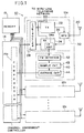
- a land site 10 is shown in block diagram form only for the purposes of illustrating this invention.
- the land site 10 includes a plurality of channel blocks 12a, 12b, ..., 12n, a channel assignment controller 14, and a memory 15.
- the arrangement of each of the channel blocks 12a, 12b, ..., 12n is identical with each other and hence the arrangement of the block 12a is only shown in detail.
- the channel block 12a includes a transmitter (TX) 22 and a receiver (RX) 24, both of which are coupled to an antenna 20 through a multiplexer 26 and also are coupled to a call controller 28. Further, the transmitter 22 and the receiver 24 are coupled to a wire-line telephone network (not shown).
- TX transmitter
- RX receiver
- the arrangement enclosed by a broken line 30, is well known in the art and hence further descriptions thereof will be omitted for clarity.
- the method of this invention is directly concerned with an arrangement which comprises the controller 14, the memory 15 and a signal level detector 40.
- the memory 15 stores the signal levels detected by the detector 40, and may be used to store the order of signal levels determined by the channel assignment controller 14.
- the signal level detector 40 comprises an FM detector 42, a sample circuit 43 and and average circuit 44.
- the FM detector 42 is coupled to an IF (Intermediate Frequency) amplifier 24a forming part of the receiver 24, and receives therefrom an IF signal of an incoming signal (FM signal) transmitted from a mobile unit and received at the antenna 20.
- the FM detector 42 generates modulating signal envelope.
- the sample circuit 43 samples the envelope at a time interval T0.
- the sampled signal levels from the circuit 43 is then applied to the average circuit 44 wherein the sampled signals are averaged at a time interval T1 (T1 is greater than T0).
- the average circuit 44 applies its output, as a detected signal level, to a comparator 14a and also to the memory 15.
- the comparator 14a forms part of the channel assignment controller 14.
- the comparator 14a functions to determine the order of the signal levels received through corresponding channels.
- the channel assignment controller 14 determines which channel is appropriate for the mobile unit to which new channel should be assigned. Further, the channel assignment controller 14 determines reassignment or rearrangement of the previously allocated and currently used channels to meet changes in received signal levels.
- channel allocation is performed such that the received signals with a large difference level are not permitted to occur in adjacent channels. The reason why such channel assignment is able to reduce interchannel interference will be discussed with reference to Fig. 2.
- FIG. 2 two frequency spectrums 50, 52 of the signals transmitted over two adjacent channels i and (i+1) are shown together with filter characteristics 54 of a band-pass filter provided for the channel (i+1).
- FM signal commonly used in a mobile communications system, has a spectrum which theoretically extends to infinite. Therefore, there exists signal spectrum of the channel i which pass through the band-pass filter of the channel (i+1). Electric power leaked into an adjacent channel through a band-pass filter produces an amount of interference. This amount of interference depends of the following parameters: a channel interval (dF), spectrum of an incoming FM signal, filtering characteristics of a band-pass filter provided for each channel, and a signal level of an interfering wave.
- dF channel interval
- interchannel interference is low when (a) spectrum width of an incoming FM signal is narrow, (b) a channel interval is large, (c) a pass range of a band-pass filter is narrow and cutoff characteristics of the filter is sharp, and (d) an interfering signal level is low.
- the parameters referred to in the above-mentioned items (a) and (b) are determined depending on what kind of modulation is adopted in a communications system, so that the values of these two parameters are determined at the system design.
- the parameters of channel interval and interfering signal level are considered.
- the interfering level itself is not significant but a ratio of an interfered (viz., desired) signal level and the aforesaid amount of interference is important.
- the signals transmitted from a plurality of mobile units and received by a land site are different in their levels, and, it is often the case that a ratio of maximum and minimum signal levels reaches more than 70 dB. Consequently, if the signals having large different levels are assigned to adjacent channels, a signal with a small level is contaminated by the adjacent strong signal. Therefore, this invention controls assignment of a channel to a mobile unit which requests a call in a manner which obviates this contamination.
- this invention changes the allocation of channels currently in use at an appropriate time interval (for example). This invention will further be discussed in detail with reference to Figs. 3, 4, 5 and 6.
- Fig. 3 shows a cell service area 60 which includes the land site 10 (Fig. 1) and four mobile units 62, 63, 64 and 66 in this case, while Fig. 4 shows signal levels received at the land site in terms of six channels 1 through 6.
- the received signal levels of the channels 1, 2, 3, 4, 5 and 6 are respectively represented L1, L2, L3, L4, L5 and L6.
- the mobile units 62, 64 and 66 are in communication with the land site 10 via the channels 2, 4 and 6, respectively, and (b) the mobile unit 63 requires a channel to be assigned.
- the received signal levels of the channels 2, 4 and 6 are shown in Fig. 4 (viz., L6 ⁇ L4 ⁇ L2). It is a assumed that the received signal level of the mobile unit 63 is detected between those of the channels 2 and 4, then the channel 3 is assigned to the mobile unit 63.
- Fig. 5 shows the received signal level of the unit 63 by a broken line and the channel 3.
- the memory 15 may be omitted wherein all the channel blocks 12a, 12b, ..., 12n continue to generate the outputs therefrom.
- channels may automatically be assigned every other channel in response to request of channel assignment from mobile units. In this case, each channel is isolated and hence there is no difficulty of interference from adjacent channels. Alternatively, it is possible to assign the call to every second and third channel. When such interval channel assignment is firstly employed, viz., when the well spaced channels are all in use, the present invention then locates the next incoming call next to a channel having the closest level thereto.
- the average circuit 44 may be replaced with a center value detector which picks up each center value during the time interval T1 of the sampled signals.
Abstract
Description
- This invention relates generally to a method of assigning a frequency channel to a mobile unit in a mobile communications system, and more specifically to such a method which features effective reduction of interchannel interference with the result of efficient use of frequency spectrum. Further, this invention relates to a method of reassigning frequency channels currently allocated to a plurality of mobile units.
- A mobile communications system including mobile-telephone services, has adopted a so-called multichannel access technique wherein when a mobile unit within a given cell requests channel access or a land site wishes to initially access a mobile unit, one is selected from a plurality of channels and is assigned to the mobile unit. According to a known technique, such a channel is randomly selected in response to each call requirement. Consequently, the conventional technique requires a sufficiently wide channel interval in order to prevent interference from adjacent channels.
- With the increasing number of subscribers, the demand for narrowing the channel interval to accommodate more channels within a limited spectrum has increased markedly. However, the above-mentioned random channel selection inherently requires a large channel space and hence is unable to meet this requirement.
- It is an object of this invention to provide a method of assigning a channel to a mobile unit which originates a call in a manner to prevent interference from adjacent channels.
- Another object of this invention is to provide a method of reassigning the currently allocated frequency channels in order to prevent interference from adjacent channels.
- One aspect of this invention takes the form of a method of assigning a channel to a mobile unit at a land site of a mobile communications system wherein the land site communicates with a plurality of mobile units through a plurality of channels, comprising the steps of: (a) receiving at the land site a signal from a first mobile unit to which a channel is to be assigned; (b) determining a signal level received at step (a); (c) determining location of the signal level among signal levels from second mobile units which are communicating with the land site; and (d) assigning a channel to the first mobile unit in a manner that the assigned channel is adjacent to a channel whose signal level is close to the signal level of the first mobile unit.
- Another aspect of this invention takes the form of a mobile unit at a land site of a mobile communications system wherein the land site communicates with a plurality of mobile units through a plurality of channels, comprising the steps of: (a) determining signal levels of the channels which are currently used to communicate mobile units with the land site; (b) determining difference of the signal levels between adjacent channels; and (c) performing reassignment if the difference between any two adjacent channels exceeds a predetermined magnitude.
- The features and advantages of the present invention will become more clearly appreciated from the following description taken in conjunction with the accompanying drawings in which like elements are denoted by like reference numerals and in which:
- Fig. 1 is a block diagram showing a land site of the nature used in the present invention;
- Fig. 2 is a graph showing spectrum of two channels expressed on frequency scale;
- Fig. 3 is a sketch showing a service cell wherein one land site is arranged to communicate with a plurality of mobile units through a plurality of channels; and
- Figs. 4, 5 and 6 are graphs each showing signal levels received at a land site in terms of channels.
- Reference is now made to Fig. 1, wherein a
land site 10 is shown in block diagram form only for the purposes of illustrating this invention. Theland site 10 includes a plurality ofchannel blocks channel assignment controller 14, and amemory 15. The arrangement of each of thechannel blocks block 12a is only shown in detail. - The
channel block 12a includes a transmitter (TX) 22 and a receiver (RX) 24, both of which are coupled to anantenna 20 through amultiplexer 26 and also are coupled to acall controller 28. Further, thetransmitter 22 and thereceiver 24 are coupled to a wire-line telephone network (not shown). The arrangement enclosed by abroken line 30, is well known in the art and hence further descriptions thereof will be omitted for clarity. - The method of this invention is directly concerned with an arrangement which comprises the
controller 14, thememory 15 and asignal level detector 40. Thememory 15 stores the signal levels detected by thedetector 40, and may be used to store the order of signal levels determined by thechannel assignment controller 14. - In the Fig. 1 arrangement, the
signal level detector 40 comprises anFM detector 42, asample circuit 43 and andaverage circuit 44. TheFM detector 42 is coupled to an IF (Intermediate Frequency)amplifier 24a forming part of thereceiver 24, and receives therefrom an IF signal of an incoming signal (FM signal) transmitted from a mobile unit and received at theantenna 20. TheFM detector 42 generates modulating signal envelope. Thesample circuit 43 samples the envelope at a time interval T0. The sampled signal levels from thecircuit 43 is then applied to theaverage circuit 44 wherein the sampled signals are averaged at a time interval T1 (T1 is greater than T0). - The
average circuit 44 applies its output, as a detected signal level, to acomparator 14a and also to thememory 15. Thecomparator 14a forms part of thechannel assignment controller 14. Thecomparator 14a functions to determine the order of the signal levels received through corresponding channels. Thechannel assignment controller 14 determines which channel is appropriate for the mobile unit to which new channel should be assigned. Further, thechannel assignment controller 14 determines reassignment or rearrangement of the previously allocated and currently used channels to meet changes in received signal levels. - According to this invention, in order to reduce interchannel interference, channel allocation is performed such that the received signals with a large difference level are not permitted to occur in adjacent channels. The reason why such channel assignment is able to reduce interchannel interference will be discussed with reference to Fig. 2.
- In Fig. 2, two
frequency spectrums filter characteristics 54 of a band-pass filter provided for the channel (i+1). FM signal, commonly used in a mobile communications system, has a spectrum which theoretically extends to infinite. Therefore, there exists signal spectrum of the channel i which pass through the band-pass filter of the channel (i+1). Electric power leaked into an adjacent channel through a band-pass filter produces an amount of interference. This amount of interference depends of the following parameters: a channel interval (dF), spectrum of an incoming FM signal, filtering characteristics of a band-pass filter provided for each channel, and a signal level of an interfering wave. - It is understood that interchannel interference is low when (a) spectrum width of an incoming FM signal is narrow, (b) a channel interval is large, (c) a pass range of a band-pass filter is narrow and cutoff characteristics of the filter is sharp, and (d) an interfering signal level is low. The parameters referred to in the above-mentioned items (a) and (b) are determined depending on what kind of modulation is adopted in a communications system, so that the values of these two parameters are determined at the system design.
- According to this invention, the parameters of channel interval and interfering signal level are considered. It should be noted that the interfering level itself is not significant but a ratio of an interfered (viz., desired) signal level and the aforesaid amount of interference is important. The signals transmitted from a plurality of mobile units and received by a land site are different in their levels, and, it is often the case that a ratio of maximum and minimum signal levels reaches more than 70 dB. Consequently, if the signals having large different levels are assigned to adjacent channels, a signal with a small level is contaminated by the adjacent strong signal. Therefore, this invention controls assignment of a channel to a mobile unit which requests a call in a manner which obviates this contamination. Further, as mobile units change their locations, the signal levels received at the land site change accordingly. To solve the problem due to this signal strength change received at a land site, this invention changes the allocation of channels currently in use at an appropriate time interval (for example). This invention will further be discussed in detail with reference to Figs. 3, 4, 5 and 6.
- Fig. 3 shows a
cell service area 60 which includes the land site 10 (Fig. 1) and fourmobile units channels 1 through 6. For the sake of convenience, the received signal levels of thechannels mobile units land site 10 via thechannels mobile unit 63 requires a channel to be assigned. The received signal levels of thechannels mobile unit 63 is detected between those of thechannels channel 3 is assigned to themobile unit 63. Fig. 5 shows the received signal level of theunit 63 by a broken line and thechannel 3. - On the other hand, let us consider the case where the received signal levels changes as the units moves while the number of mobile units communicating with the land site remains unchanged. It is assumed that only L2 changes lower than L3 as shown in Fig. 6, then the signal of the
channel 3 interferes with thechannel 2. Therefore, themobile unit 62, which presently usechannel 2, is forced to change tochannel 1 as shown. Such channel changes may be carried out, for example, by periodic examination of each of the mobile unit signals. This reassignment of channels can be carried out upon the level of any two adjacent channels reaching and/or exceeding a predetermined magnitude. - In Fig. 1, the
memory 15 may be omitted wherein all thechannel blocks - In the above discussion, if there is a group of unused channels which are continuously positioned on a frequency axis, channels may automatically be assigned every other channel in response to request of channel assignment from mobile units. In this case, each channel is isolated and hence there is no difficulty of interference from adjacent channels. Alternatively, it is possible to assign the call to every second and third channel. When such interval channel assignment is firstly employed, viz., when the well spaced channels are all in use, the present invention then locates the next incoming call next to a channel having the closest level thereto.
- It should be noted that the circuit arrangements of the
signal level detector 40 and thechannel assignment controller 14 are illustrated only by way of example. Theaverage circuit 44 may be replaced with a center value detector which picks up each center value during the time interval T1 of the sampled signals. - The foregoing description shows only preferred embodiments of the present invention. Various modifications are apparent to those skilled in the art without departing from the scope of this invention which is only limited by the appended claims.
Claims (4)
Applications Claiming Priority (2)
| Application Number | Priority Date | Filing Date | Title |
|---|---|---|---|
| JP229610/87 | 1987-09-16 | ||
| JP62229610A JPS6473926A (en) | 1987-09-16 | 1987-09-16 | Channel assignment method for mobile communication system |
Publications (3)
| Publication Number | Publication Date |
|---|---|
| EP0308253A2 true EP0308253A2 (en) | 1989-03-22 |
| EP0308253A3 EP0308253A3 (en) | 1990-05-16 |
| EP0308253B1 EP0308253B1 (en) | 1993-12-22 |
Family
ID=16894873
Family Applications (1)
| Application Number | Title | Priority Date | Filing Date |
|---|---|---|---|
| EP88308610A Expired - Lifetime EP0308253B1 (en) | 1987-09-16 | 1988-09-16 | Method of assigning frequency channel in mobile communications system |
Country Status (5)
| Country | Link |
|---|---|
| US (1) | US5109529A (en) |
| EP (1) | EP0308253B1 (en) |
| JP (1) | JPS6473926A (en) |
| AU (1) | AU611479B2 (en) |
| CA (1) | CA1312918C (en) |
Cited By (8)
| Publication number | Priority date | Publication date | Assignee | Title |
|---|---|---|---|---|
| EP0410670A2 (en) * | 1989-07-24 | 1991-01-30 | Nec Corporation | Channel selection system for mobile radio communication equipment |
| EP0411878A2 (en) * | 1989-08-03 | 1991-02-06 | Orbitel Mobile Communications Limited | Power control arrangement for a radio communication system |
| EP0419205A2 (en) * | 1989-09-19 | 1991-03-27 | Nippon Telegraph And Telephone Corporation | A channel assignment system |
| US5050234A (en) * | 1989-03-30 | 1991-09-17 | Nec Corp. | Method for connecting a channel between a base station and a mobile station |
| WO1993020624A1 (en) * | 1992-03-28 | 1993-10-14 | Motorola Limited | Communications system with extended channels |
| US5678189A (en) * | 1992-03-28 | 1997-10-14 | Motorola, Inc. | Communications system and communications unit for communicating over a base set of channels and an extended set of channels |
| US5708969A (en) * | 1991-11-25 | 1998-01-13 | Motorola, Inc. | Reduced interference through frequency partitioning |
| WO1998015153A1 (en) * | 1996-10-01 | 1998-04-09 | Ericsson Inc. | Method and apparatus for mitigating intermodulation effects in multiple-signal transmission systems |
Families Citing this family (15)
| Publication number | Priority date | Publication date | Assignee | Title |
|---|---|---|---|---|
| EP0610209A1 (en) * | 1991-05-17 | 1994-08-17 | Motorola, Inc. | Channel acquisition method and apparatus for a communication system |
| US5218630A (en) * | 1992-05-06 | 1993-06-08 | Motorola, Inc. | Method for channel utilization in extended spectrum communication systems |
| US5497503A (en) * | 1993-05-28 | 1996-03-05 | Ameritech Corporation | Method for assigning frequency channels in a cellular communication system and for identifying critical existing fixed microwave receivers that restrict operation of such a system |
| JPH0722992A (en) * | 1993-06-22 | 1995-01-24 | Nec Corp | Mobile communication base station device |
| US5499388A (en) * | 1993-10-20 | 1996-03-12 | Polk's Model Craft Hobbies, Inc. | Radio with frequency scanning and interference detection capability for remote controlled model aircraft |
| US5726978A (en) * | 1995-06-22 | 1998-03-10 | Telefonaktiebolaget L M Ericsson Publ. | Adaptive channel allocation in a frequency division multiplexed system |
| US5790516A (en) * | 1995-07-14 | 1998-08-04 | Telefonaktiebolaget Lm Ericsson | Pulse shaping for data transmission in an orthogonal frequency division multiplexed system |
| US5878328A (en) * | 1995-12-21 | 1999-03-02 | At&T Wireless Services, Inc. | Method and apparatus for wireless communication system organization |
| US6496700B1 (en) * | 1996-04-04 | 2002-12-17 | At&T Wireless Services, Inc. | Method for determining organization parameters in a wireless communication system |
| US6049774A (en) * | 1996-07-08 | 2000-04-11 | At&T Corp. | Machine, method and medium for dynamic optimization for resource allocation |
| US5960351A (en) * | 1997-02-26 | 1999-09-28 | Ericsson Inc. | Radio frequency planning and assignment in a discontiguous spectrum environment |
| US6389273B1 (en) * | 1999-08-23 | 2002-05-14 | Delphi Technologies, Inc. | Adjacent channel interference reduction in a FM receiver |
| US7949344B1 (en) | 2006-02-13 | 2011-05-24 | Wireless Strategies, Inc. | Uncoordinated microwave paths in coordinated frequency bands |
| US8078109B1 (en) | 2007-04-13 | 2011-12-13 | Wireless Stategies, Inc. | Concurrently coordinated microwave paths in coordinated frequency bands |
| US11063675B2 (en) | 2019-03-05 | 2021-07-13 | Cisco Technology, Inc. | Wireless spectrum management and optimization for dual transceiver operation |
Citations (3)
| Publication number | Priority date | Publication date | Assignee | Title |
|---|---|---|---|---|
| US3764915A (en) * | 1971-06-25 | 1973-10-09 | Bell Telephone Labor Inc | Dynamic program control for channel assignment in mobile communication systems |
| EP0038518A1 (en) * | 1980-04-17 | 1981-10-28 | Siemens Aktiengesellschaft | Mobile radio network |
| EP0202485A2 (en) * | 1985-04-22 | 1986-11-26 | Nec Corporation | Method of determining optimal transmission channel in multistation communications system |
Family Cites Families (7)
| Publication number | Priority date | Publication date | Assignee | Title |
|---|---|---|---|---|
| JPS56126339A (en) * | 1980-03-10 | 1981-10-03 | Nec Corp | Mobile communication system |
| US4654879A (en) * | 1985-03-29 | 1987-03-31 | Itt Corporation | Cellular mobile radio subscriber location detection |
| US4736453A (en) * | 1985-12-10 | 1988-04-05 | Schloemer Gerald R | Method and apparatus for making frequency channel assignment in a cellular or non-cellular radiotelephone communications system |
| US4672657A (en) * | 1985-12-17 | 1987-06-09 | Motorola, Inc. | Multichannel telephone system |
| US4794635A (en) * | 1986-11-28 | 1988-12-27 | Motorola, Inc. | Two-way radio communication system with max-minimum call assignment method |
| CA1282837C (en) * | 1987-03-20 | 1991-04-09 | Tetsuya Hanawa | Apparatus for selecting control channel in mobile communication system |
| SE460941B (en) * | 1988-04-26 | 1989-12-04 | Ericsson Telefon Ab L M | PROCEDURE IN A CELL-DIVIDED MOBILE PHONE SYSTEM TO REDUCE SUSPENSION BY TRANSFER OF CALLS |
-
1987
- 1987-09-16 JP JP62229610A patent/JPS6473926A/en active Granted
-
1988
- 1988-09-15 CA CA000577495A patent/CA1312918C/en not_active Expired - Fee Related
- 1988-09-16 US US07/245,193 patent/US5109529A/en not_active Expired - Fee Related
- 1988-09-16 EP EP88308610A patent/EP0308253B1/en not_active Expired - Lifetime
- 1988-09-16 AU AU22342/88A patent/AU611479B2/en not_active Ceased
Patent Citations (3)
| Publication number | Priority date | Publication date | Assignee | Title |
|---|---|---|---|---|
| US3764915A (en) * | 1971-06-25 | 1973-10-09 | Bell Telephone Labor Inc | Dynamic program control for channel assignment in mobile communication systems |
| EP0038518A1 (en) * | 1980-04-17 | 1981-10-28 | Siemens Aktiengesellschaft | Mobile radio network |
| EP0202485A2 (en) * | 1985-04-22 | 1986-11-26 | Nec Corporation | Method of determining optimal transmission channel in multistation communications system |
Cited By (15)
| Publication number | Priority date | Publication date | Assignee | Title |
|---|---|---|---|---|
| US5050234A (en) * | 1989-03-30 | 1991-09-17 | Nec Corp. | Method for connecting a channel between a base station and a mobile station |
| EP0410670A3 (en) * | 1989-07-24 | 1992-05-06 | Nec Corporation | Channel selection system for mobile radio communication equipment |
| EP0410670A2 (en) * | 1989-07-24 | 1991-01-30 | Nec Corporation | Channel selection system for mobile radio communication equipment |
| EP0411878A2 (en) * | 1989-08-03 | 1991-02-06 | Orbitel Mobile Communications Limited | Power control arrangement for a radio communication system |
| GB2235853A (en) * | 1989-08-03 | 1991-03-13 | Orbitel Mobile Communications | Power control led channel assignment for radio communication system |
| AU633946B2 (en) * | 1989-08-03 | 1993-02-11 | Orbitel Mobile Communications Limited | Power control arrangement for a radio communication system |
| EP0411878A3 (en) * | 1989-08-03 | 1992-02-05 | Orbitel Mobile Communications Limited | Power control arrangement for a radio communication system |
| EP0419205A3 (en) * | 1989-09-19 | 1992-04-29 | Nippon Telegraph And Telephone Corporation | A channel assignment system |
| EP0419205A2 (en) * | 1989-09-19 | 1991-03-27 | Nippon Telegraph And Telephone Corporation | A channel assignment system |
| US5708969A (en) * | 1991-11-25 | 1998-01-13 | Motorola, Inc. | Reduced interference through frequency partitioning |
| WO1993020624A1 (en) * | 1992-03-28 | 1993-10-14 | Motorola Limited | Communications system with extended channels |
| US5678189A (en) * | 1992-03-28 | 1997-10-14 | Motorola, Inc. | Communications system and communications unit for communicating over a base set of channels and an extended set of channels |
| WO1998015153A1 (en) * | 1996-10-01 | 1998-04-09 | Ericsson Inc. | Method and apparatus for mitigating intermodulation effects in multiple-signal transmission systems |
| US6061568A (en) * | 1996-10-01 | 2000-05-09 | Ericsson Inc. | Method and apparatus for mitigating intermodulation effects in multiple-signal transmission systems |
| AU724436B2 (en) * | 1996-10-01 | 2000-09-21 | Ericsson Inc. | Method and apparatus for mitigating intermodulation effects in multiple-signal transmission systems |
Also Published As
| Publication number | Publication date |
|---|---|
| AU611479B2 (en) | 1991-06-13 |
| JPH0547137B2 (en) | 1993-07-15 |
| US5109529A (en) | 1992-04-28 |
| AU2234288A (en) | 1989-03-16 |
| JPS6473926A (en) | 1989-03-20 |
| CA1312918C (en) | 1993-01-19 |
| EP0308253A3 (en) | 1990-05-16 |
| EP0308253B1 (en) | 1993-12-22 |
Similar Documents
| Publication | Publication Date | Title |
|---|---|---|
| US5109529A (en) | Method of assigning frequency channel in mobile communications system | |
| US6374124B1 (en) | Dynamic reallocation of transceivers used to interconnect wireless telephones to a broadband network | |
| US6178329B1 (en) | Method and apparatus for dynamic channel allocation for wireless communications using channel occupancy data | |
| KR0146232B1 (en) | Method and apparatus for optimum channel assignments | |
| US4747101A (en) | Method of determining optimal transmission channel in multi-station communications system | |
| US6018663A (en) | Frequency packing for dynamic frequency allocation in a radiocommunication system | |
| US6192216B1 (en) | Remotely controlled gain control of transceiver used to inter-connect wireless telephones to a broadband network | |
| US6223021B1 (en) | Signal filtering in a transceiver for a wireless telephone system | |
| US5771454A (en) | Base station allocation method for mobile radio communication system | |
| US4551852A (en) | Process for spreading the volume of traffic over different control channels of a cellular radio transmission system | |
| WO1998059435A1 (en) | A method to allocate channels for a fixed radio link operating in an non-coordinated frequency band | |
| KR930022756A (en) | Partitioning Method of Dynamic Channel Assignment in Mobile Communication Systems | |
| US5206882A (en) | System for and method of creating and assigning address codes in a cellular spread spectrum system | |
| WO1997014259A1 (en) | A method for frequency allocation and assignment in wireless communication systems | |
| EP0629097A2 (en) | Mobile communication apparatus | |
| US6131033A (en) | Methods and systems of performing system channel planning for wireless local loop communication | |
| US6317423B1 (en) | Method for controlling a base station, and base station | |
| AU4013299A (en) | Method of transmitting in successive time slots | |
| EP1064758B1 (en) | Method and system for wireless telecommunications | |
| JP3080204B2 (en) | Channel switching method during communication of spread spectrum mobile communication | |
| US7428423B2 (en) | Communication system with controlled talk around mode | |
| KR100222270B1 (en) | Dymanic channel allocating apparatus for controlling subnetwork of satellite communication system | |
| KR960003841B1 (en) | Two-way communication system | |
| JP3358973B2 (en) | Switching method for interference channel | |
| JPH01173929A (en) | Satellite communication system |
Legal Events
| Date | Code | Title | Description |
|---|---|---|---|
| PUAI | Public reference made under article 153(3) epc to a published international application that has entered the european phase |
Free format text: ORIGINAL CODE: 0009012 |
|
| 17P | Request for examination filed |
Effective date: 19880929 |
|
| AK | Designated contracting states |
Kind code of ref document: A2 Designated state(s): GB NL SE |
|
| PUAL | Search report despatched |
Free format text: ORIGINAL CODE: 0009013 |
|
| AK | Designated contracting states |
Kind code of ref document: A3 Designated state(s): GB NL SE |
|
| 17Q | First examination report despatched |
Effective date: 19920720 |
|
| GRAA | (expected) grant |
Free format text: ORIGINAL CODE: 0009210 |
|
| AK | Designated contracting states |
Kind code of ref document: B1 Designated state(s): GB NL SE |
|
| PG25 | Lapsed in a contracting state [announced via postgrant information from national office to epo] |
Ref country code: NL Effective date: 19931222 Ref country code: SE Effective date: 19931222 |
|
| NLV1 | Nl: lapsed or annulled due to failure to fulfill the requirements of art. 29p and 29m of the patents act | ||
| PLBE | No opposition filed within time limit |
Free format text: ORIGINAL CODE: 0009261 |
|
| STAA | Information on the status of an ep patent application or granted ep patent |
Free format text: STATUS: NO OPPOSITION FILED WITHIN TIME LIMIT |
|
| 26N | No opposition filed | ||
| REG | Reference to a national code |
Ref country code: GB Ref legal event code: IF02 |
|
| PGFP | Annual fee paid to national office [announced via postgrant information from national office to epo] |
Ref country code: GB Payment date: 20020911 Year of fee payment: 15 |
|
| PG25 | Lapsed in a contracting state [announced via postgrant information from national office to epo] |
Ref country code: GB Free format text: LAPSE BECAUSE OF NON-PAYMENT OF DUE FEES Effective date: 20030916 |
|
| GBPC | Gb: european patent ceased through non-payment of renewal fee |
Effective date: 20030916 |