EP0308229A2 - Sea clutter suppression radar - Google Patents
Sea clutter suppression radar Download PDFInfo
- Publication number
- EP0308229A2 EP0308229A2 EP88308553A EP88308553A EP0308229A2 EP 0308229 A2 EP0308229 A2 EP 0308229A2 EP 88308553 A EP88308553 A EP 88308553A EP 88308553 A EP88308553 A EP 88308553A EP 0308229 A2 EP0308229 A2 EP 0308229A2
- Authority
- EP
- European Patent Office
- Prior art keywords
- output
- detectors
- outputs
- signals
- horizontally
- Prior art date
- Legal status (The legal status is an assumption and is not a legal conclusion. Google has not performed a legal analysis and makes no representation as to the accuracy of the status listed.)
- Granted
Links
Images


Classifications
-
- G—PHYSICS
- G01—MEASURING; TESTING
- G01S—RADIO DIRECTION-FINDING; RADIO NAVIGATION; DETERMINING DISTANCE OR VELOCITY BY USE OF RADIO WAVES; LOCATING OR PRESENCE-DETECTING BY USE OF THE REFLECTION OR RERADIATION OF RADIO WAVES; ANALOGOUS ARRANGEMENTS USING OTHER WAVES
- G01S7/00—Details of systems according to groups G01S13/00, G01S15/00, G01S17/00
- G01S7/02—Details of systems according to groups G01S13/00, G01S15/00, G01S17/00 of systems according to group G01S13/00
- G01S7/024—Details of systems according to groups G01S13/00, G01S15/00, G01S17/00 of systems according to group G01S13/00 using polarisation effects
Definitions
- the present invention relates to sea clutter suppression radar.
- the correlation method is to correlate a target signal with a reflected signal from the sea surface by making use of addition and multiplication or a combination thereof, etc., when those signals are varied temporarily or owing to a change in the characterisitcs of the associated radar radiowaves.
- signals reflected from the sea surface are changed slowly in time compared with the period of a pulse from a radar.
- the method to take the correlation between signals shifted in time to each other or between signals changed in their planes of polarization to each other or the method in combination thereof is accordingly incapable of affording sufficient effects.
- a technique was developed to take the correlation by varying the frequency of radar radiowaves. That is, the technique is adapted to take multiple correlation among four signals: orthogonal two polarized waves and two frequencies as disclosed in the aforementioned reference.
- the present invention includes: a single or a plurality of antennas for simultaneously sending horizontally and vertically polarized; first and second detectors each for detecting intermediate frequency (IF) signals of horizontally and vertically polarized components of reflected radiowaves; third and fourth detectors each for detecting IF signals of the vector sum of and vector differnce between the horizontally and vertically polarized components; and a polar signal generator for genarating a polar signal based upon a subtraction output between an addition output of both outputs of the first and second detectors, and a unipolar conversion output of a subtraction output between said both outputs and upon a subtraction output between the outputs of the third and fourth detectors.
- IF intermediate frequency
- the present invention includes a mean fraction removal circuit for removing a mean fraction from an addition output of outputs from the third and fourth detectors after they are respectively subtracted from an output as the result of the unipolar conversion; and a polarity converter for converting the polarity of an output from the mean fraction removal circuit in conformity with an output from the polar signal generator.
- Fig. 1 is a block diagram illustrating the arrangement of an embodiment of sea clutter suppression radar according to the present invention.
- 10 is a transmitter for sending pulsed radiowaves of a single frequency
- 11 is a circulator for transmitting the pulsed radiowaves in the direction of the arrow illustrated
- 12 is a polarization divider
- 13 is a circular polarizer for circularly polarized wave of a quarter-wave type including a dielectic plate mounted thereon, which is slanted 45° left upwadly when viewed from the direction of propagation of the sent radiowaves
- 14 is an antenna
- 15 is a phase shifter
- 16 is a hybrid circuit for delivering to terminals 4 and 3 the vector sum of and vector difference between input signals at terminals 1 and 2,17 and 18 are limiters
- 19 and 20 are mixers
- 21 is a local oscillator
- 22 and 23 are intermediate frequency (IF) amplifiers
- 24, 25, 28, and 29 are detectors for effecting envelope detection for IF signals
- 26 is
- the transmitter 10 generates pulsed radiowaves which are in turn sent, after passing through the circulator 11, to the polarization divider 12 as horizontally polarized radiowaves having a horizontal electric field component.
- the radiowaves pass through the polarization divider 12 as they are and are sent to the circular polarizer 13 for circularly polarized wave as a horizontally polarized wave, whereby they are converted to a right-handed circularly polarized wave and radiated to the outside through the antenna 14.
- the reflected wave from a target, elliptically polarized in general, is received by the antenna 14 and sent to the circular polarizer 13 for circularly polarized wave.
- amplitudes and phases of horizontally and vertically polarized components of the received radiowaves are as E H , Ev, and ( PH , ⁇ v, both polarized components produce a phase difference of 90° between electric field components thereof perpendicular and parallel to a dielectric plate disposed in the circular polarizer 13 for circularly polarized wave after propagation of the dielectic plate.
- horizontally and vertically polarized components F H and Fv of the radiowaves received by the polarizer 14 are expressed respectively by:
- the predetermined phase shift described above means an aditional phase change added by the phase shifter 15 to the vertically polarized wave output and required for the propagation phase difference between the horizontally and vertically polarized waves becoming 90° until these waves reach from the polarization divider 12 to the hybrid circuit 16.
- signals as the vector sum and vector difference between the input signals to the terminals 1 and 2: are outputted.
- These two signals are, after passage through the limiters 17 and 18 respectively, converted to IF signals by the mixers 19 and 20, and, after amplification by the IF amplifiers 22 and 23, outputted as the IF signals.
- the outputs from the IF amplifiers 22 and 23 described above are given by signals:
- E 1 ( > 0) and E 2 ( > 0) respectively express that the amplitudes E H and Ev of the horizontally and vertically polarized components of the received radiowaves of these amplitudes E H and Ev are changed mainly through the amplitude characteristics of the IF amplifiers 22 and 23. Moreover, common terms of amplitudes and phases to both signals are omitted here.
- the detectors 24 and 25 output
- E and
- E 2 respectively, while the detectors 28 and 29 outputting
- the amplitude Z of an output from the subtracter 34 is given by
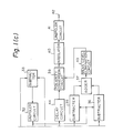
- Fig. 9 designated at 300 is an input terminal for the output from the adder 37, 301 is a delay circuit having the same delay time as that of the filter 302, 302 is a filter for eliminating longer, in time, signals than a target signal, 303 is a subtracter for subtracting the output from the filter 302 from the output from the delay circuit 301, and 304 is an output terminal, an output from which is fed to the polarity conversion circuit 39.
- the delay circuit 44 having the same delay time as that of the mean level elimination circuit 43 serves to time an output from the polarity signal generator 38 with that from the mean level elimination circuit 43.
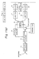
- the polarity conversion circuit 39 is arranged as illustrated in Fig. 4.
- designated at 200 is an output terminal for the output from the mean level elimination circuit 43
- 201 is an inverting amplifier of the gain 1
- 202 is a switch circuit, which is operated to be connected to the opposite side when a signal at an input terminal 204 is
- 204 is an input terminal for the output from the delay circuit 44
- 203 is an output terminal.
- an output from the polarity conversion circuit 39 will be considered for illustration of the reflected signal from the sea surface, taking as an example a signal reflected from the sea surface when the amplitude ratio r and the phase difference y both at each pulse repetition period are changed as illustrated as Figs. 6(a) and 6(b).
- the amplitude Y of the output from the adder 37 remains substantially constant with respect to the phase difference y , and a change in the same at each pulse repetition is reduced as illustrated for example in Fig. 6(c) because of a slow temporal change in the reflected signal from the sea surface.
- the outout from the mean level elimination circuit 43 which is obtained by removing a mean fraction from the above output from the adder 37, is also reduced in the amplitude change, as illustrated for example in Fig. 6(d).
- the polarity of the output may be changed oppositely to that shown in Fig.
- the bipolar signal is fed to the integrator 40 and added to n signals at each pulse repetition but when those n signals include bipolar signals, they cancel each other to cause the amplitude of the output from the integrator 40 to be reduced. That is, the signal reflected from the sea surface is suppressed.
- bipolar signals appear at the output of the integrator 40, they are fed to the unipolar circuit 41, by which they are converted to predetermined unipolar signals and delivered to the output terminal.
- the addition of the n signals in the integrator 40 causes, since the changes in the amplitudes themselves of the signals are small as in the previous description, adjacent small signal groups to cancel each other when n > m.
- the integrator 40 only one, at most, small signal group contributes to the output of the integrator 40 to assure the voltage of mV at the highest as the amplitude of the above output.
- a reflecting surface for radar radiowaves is structured as a solid.
- the amplitude ratio r and the phase difference y are made substantially unchanged during the hits of radar pulses, and also the output from the polarity conversion circuit 39 is made substantially constant in its amplitude and polarity.
- the output amplitude of the integrator 40 is thus n Vs.
- Vs is the target output amplitude of the polarity conversion circuit 39.
- the ratio of the target signal to the signal yielded by removing the mean fraction from the reflected signal from the sea surface substantially exceeds V'c.
- the improved ratio S/C by the integration in the video signal region is substantially above n/m proportional to the first power of the number of additions of the signal. That is, in the present invention, the improved ratio S/C is proportional to the first power of the number of additions, so that an increase of the addition number n assures a more effective improvement of the ratio S/C than in the prior method where the number of frequencies used is increased.
- the aforementioned number m of signals may be reduced so as to further improve the ratio S/C.
- Reflected radiowaves from the sea surface are frequently different in the amplitudes of both polarized waves thereof from each other so that the amplitude Y is reduced responsively to the amplitude ratio of both polarized waves, while reflected radiowaves from a general target sees no great difference between the amplitudes of both polarized waves so that the amplitude Y is not reduced in particular.
- the signal to clutter voltage ratio may be improved for the reflected signal from the sea surface.
- W H (f) and Wv(f) are power spectral densities of horizontally and vertically polarized radiowaves
- WHO and W vo are power spectral densities of the horizontally and vertically polarized radiowaves at the center of the spectrum
- f H and fv are center frequencies of the spectrum of the horizontally and vertically polarized radiowaves
- ⁇ H and ⁇ v are spreadings of the spectrum (standard deviation) of the horizontally and vertically polarized radiowaves.
- the effective value Af rms of a difference frequency of both polarized radiowaves is, since there is no correlation between the spectrums of both polarized radiowaves, expressed as follows:
- Fig. 7 illustrates another embodiment of the present invention wherein different portions from those shown in Fig. 1 are shown.
- designated at 50 is a 90° phase shifter for the IF signal
- 51 and 52 are IF amplifiers each for amplifying the voltage of the IF signal to dreuble the same.
- the polarization branching filter 12 after receiving a signal outputs the two pqlarized components F v and F H as in the embodiment of Fig. 1. These signals are after passage through mixers 17 and 18, converted to IF signals by mixers 19 and 20, and amplified by IF amplifiers 22 and 23.
- the IF amplifier 22 outputs 1 / 2 e (E 1 - E 2 ) as an IF signal corresponding to and hence the phase shifter 50 outputs m IF signal 1 / 2 (E1 - E2 ). While, the IF amplifier 23 outputs 1 / 2 (E1 + E 2 ) as a signal corresponding to
- E 1 and E 2 are here the same as those described before.
- E 1 , E 2 , E 1 + E 2 , and E 1 - E 2 appear as IF signals at output terminals of an adder 26, a subtracter 27, an IF amplifier 51, and an IF amplifier 52, respectively.
- Those IF signals are the same as the IF signals inputted to the detectors 24, 25, 28, and 29 of the embodiment of Fig. 1, and hence operation of the present embodiment is the same as in the embodiment of Fig. 1.
- Fig. 8 illustrates a further another embodiment of the present invention wherein different portions from those illustrated in Fig. 1 are shown.
- designated at 61 is a distributor
- 62 and 63 are circulators
- 64 and 65 are antennas, one for sending horizontally and vertically polarized radiowaves, the other for receiving the same.
- Pulsed radiowaves generated by a transmitter 10 of Fig. 8 are divided into two waves by the distributor 61, which are then transmitted to the circulators 62 and 63 and sent through the antennas as horizontally and vertically polarized radiowaves, respectively.
- a horizontally polarized component between reflected radiowaves from a target is received by the antenna 64 while a vertically polarized one received by the antenna 65, both components being then transmitted to the circulators 62 and 63.
- Horizontally and vertically polarized components of the received radiowaves transmitted from the circulators 62 and 63 are fed to the limiters 17 and 18. Operation thereafter is the same as in the embodiment of Fig. 1. Assuming here the amplitudes and phases of the horizontally and vertically polarized components of the received radiowaves in the embodiment of Fig.
- Fig. 1 may be modified such that the subtractors 35 and 36 are removed and the outputs from the detectors 28 and 29 are directly connected to the adder 37. But, the previous feature, in which for the amplitude of the output from the adder 37 that corresponding to one component having a smaller amplitude between both polarized components of the reflected radiowaves is assured differing from the amplitude Y described previously, is thereupon missed.
- the embodiment of Fig. 1 may be modified such that the mean level elimination circuit 43 and the delay circuit 44 are removed, and the outputs from the adder 37 and polarity signal generator 38 are directly fed to the polarity conversion circuit 39. But, the mean fraction included in the output from the adder 37 thereupon remains as it is, so that the amplitude of the output from the polarity conversion circuit 39 for a reflected signal from the sea surface is slightly increased.
- the embodiment of Fig. 1 may further be modified such that an A/D converter is inserted after the detectors 24, 25, 28 and 29 of Fig. 1, and outputs from the respective detectors are converted to digital signals to process all operation after that of Fig. 1 in a digital form.
Landscapes
- Engineering & Computer Science (AREA)
- Computer Networks & Wireless Communication (AREA)
- Physics & Mathematics (AREA)
- General Physics & Mathematics (AREA)
- Radar, Positioning & Navigation (AREA)
- Remote Sensing (AREA)
- Radar Systems Or Details Thereof (AREA)
Abstract
Description
- The present invention relates to sea clutter suppression radar.
- It is often experienced, when a radar senses any target on the sea, that the radar may receive not only a true signal reflected from the target but also a false signal reflected from waves on the sea and thus be obliged to be hindered from sensing the target. There are known various techniques to suppress such a reflected signal from waves on the sea, among which a technique to correlate those signals is widely known to be effective. The correlation method is to correlate a target signal with a reflected signal from the sea surface by making use of addition and multiplication or a combination thereof, etc., when those signals are varied temporarily or owing to a change in the characterisitcs of the associated radar radiowaves. However, signals reflected from the sea surface are changed slowly in time compared with the period of a pulse from a radar. The method to take the correlation between signals shifted in time to each other or between signals changed in their planes of polarization to each other or the method in combination thereof is accordingly incapable of affording sufficient effects. To solve this, a technique was developed to take the correlation by varying the frequency of radar radiowaves. That is, the technique is adapted to take multiple correlation among four signals: orthogonal two polarized waves and two frequencies as disclosed in the aforementioned reference.
- However, such a technique to use a plurality of frequencies suffers from a problem that it must occupy many frequencies having public character so that the associated radar equipment is complicated and costly the more.
- In view of the drawbacks of the prior art, it is an object of the present invention to provide sea clutter suppression radar capable of effectively suppressing the reflected signal with use of radiowaves of a single frequency by simultaneously sending the radiowaves each having horizontal and vertical polarizations, detecting, from a reflected signal from a target, horizontally and vertically polarized components and the vector sum of and vector difference signals between components, and processing those signals to suppress the reflected signal from the sea surface.
- To achieve the above object, the present invention includes: a single or a plurality of antennas for simultaneously sending horizontally and vertically polarized; first and second detectors each for detecting intermediate frequency (IF) signals of horizontally and vertically polarized components of reflected radiowaves; third and fourth detectors each for detecting IF signals of the vector sum of and vector differnce between the horizontally and vertically polarized components; and a polar signal generator for genarating a polar signal based upon a subtraction output between an addition output of both outputs of the first and second detectors, and a unipolar conversion output of a subtraction output between said both outputs and upon a subtraction output between the outputs of the third and fourth detectors.
- Additionally, the present invention includes a mean fraction removal circuit for removing a mean fraction from an addition output of outputs from the third and fourth detectors after they are respectively subtracted from an output as the result of the unipolar conversion; and a polarity converter for converting the polarity of an output from the mean fraction removal circuit in conformity with an output from the polar signal generator. The above and other objects, features and advantages of the present invention will become more apparent from the following description when taken in conjunction with the accompanying drawings in which a preferred embodiment of the present invention is shown by way of illustrative example.
-
- Fig. 1 is a block diagram illustrating the arrangement of an embodiment of sea clutter suppression radar according to the present invention;
- Fig. 2 is a view illustrating the characteristics of y and z derived from an expression described later wherein (a) shows a relationship between y and Irl, taking the ratio of amplitudes as a parameter, and (b) shows a relationship between z and |γ| taking the same ratio of amplitudes;
- Fig. 3 is a block diagram illustrating the arrangement of a
polarity signal generator 38; - Fig. 4 is a block diagram illustrating the arrangement of a
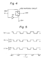
polarity conversion circuit 39 of Fig. 1; - Fig. 5 is a view illustrating the output characteristics of the
polarity signal generator 38 of Fig. 1; - Fig. 6 is a view illustrating outputs, etc., from respective portions of the equipment for explaining the output from the radar of Fig. 1;
- Fig. 7 is a block diagram illustrating another embodiment of the present invention;
- Fig. 8 is a block diagram illustrating further another embodiment of the present invention;
- Fig. 9 is a block diagram illustrating the arrangement of a mean
level elimination circuit 43 of Fig. 1; and - Fig. 10 is a truth table listing an output e of an
OR circuit 120 with respect to output signals a, b, c and d of comparators 108,109,110, and 111 of Fig. 3. - Fig. 1 is a block diagram illustrating the arrangement of an embodiment of sea clutter suppression radar according to the present invention. In the figure, designated at 10 is a transmitter for sending pulsed radiowaves of a single frequency, 11 is a circulator for transmitting the pulsed radiowaves in the direction of the arrow illustrated, 12 is a polarization divider, 13 is a circular polarizer for circularly polarized wave of a quarter-wave type including a dielectic plate mounted thereon, which is slanted 45° left upwadly when viewed from the direction of propagation of the sent radiowaves, 14 is an antenna, 15 is a phase shifter, 16 is a hybrid circuit for delivering to
terminals terminals subtractors adder 37 through its filter and subtracting the resulting signal from the above output signal to remove the mean fraction of the above output, 39 is a polarity conversion circuit for receiving an output signal from the meanlevel elimination circuit 43 and the binary signal from thedelay circuit 44 to convert the polarity of the former output signal to the original one or a reversed one conformably to the binary singal, 40 is an integrator with the number of addition being n for receving an output from thepolarity conversion circuit 39 to store the same over past n pulse repetition periods thereof and add in succession the same and n signals of the same propagation distance as that of the present signal, 41 is a unipolar circuit for converting a bipolar signal delivered from theintegrater 40 to a unipolar one, and 42 is the output terminal for a video signal. - In succession, operation of the embodiment will be described.
- The
transmitter 10 generates pulsed radiowaves which are in turn sent, after passing through thecirculator 11, to thepolarization divider 12 as horizontally polarized radiowaves having a horizontal electric field component. The radiowaves pass through thepolarization divider 12 as they are and are sent to thecircular polarizer 13 for circularly polarized wave as a horizontally polarized wave, whereby they are converted to a right-handed circularly polarized wave and radiated to the outside through theantenna 14. The reflected wave from a target, elliptically polarized in general, is received by theantenna 14 and sent to thecircular polarizer 13 for circularly polarized wave. Now expressed amplitudes and phases of horizontally and vertically polarized components of the received radiowaves are as EH, Ev, and (PH, ϕv, both polarized components produce a phase difference of 90° between electric field components thereof perpendicular and parallel to a dielectric plate disposed in thecircular polarizer 13 for circularly polarized wave after propagation of the dielectic plate. Thereupon, horizontally and vertically polarized components FH and Fv of the radiowaves received by thepolarizer 14 are expressed respectively by:

- These two polarized components FH and Fv are sent to the
polarization divider 12, through which the horizontally polarized component FH is transmitted to the same terminal as the input terminal for the received radiowaves while the vetically polarized component Fv transmitted to the other terminal. The horizontally polarized wave output from thepolarization divider 12 is, after passage through thecirculator 11, inputted into theterminal 2 of thehybrid circuit 16, while the vertically polarized wave output from the same, after passage through thephase shifter 15 followed by a predetermined phase shift, being inputted into the input terminal of thehybrid circuit 16. The predetermined phase shift described above means an aditional phase change added by thephase shifter 15 to the vertically polarized wave output and required for the propagation phase difference between the horizontally and vertically polarized waves becoming 90° until these waves reach from thepolarization divider 12 to thehybrid circuit 16. To theterminals hybrid circuit 16, signals as the vector sum and vector difference between the input signals to theterminals 1 and 2:

are outputted. These two signals are, after passage through thelimiters mixers IF amplifiers limiters mixers IF amplifiers IF amplifiers 

- Here, E1 ( > 0) and E2 ( > 0) respectively express that the amplitudes EH and Ev of the horizontally and vertically polarized components of the received radiowaves of these amplitudes EH and Ev are changed mainly through the amplitude characteristics of the
IF amplifiers detectors detectors unipolar circuit 32 provides |E1- E2|, the amplitude Y of an output from theadder 37 is given by
- The amplitude Z of an output from the
subtracter 34 is given by
- Rewritten here Y and Z with substitution E2/E1= r, ϕv -ϕH + ω/2 = y , Y/E1=y, Z/Ei-z,

hold. - Fig. 2 illustrates the characteristics of y and z, wherein (a) shows a relationship between y and |γ| taking the amplitude ratio r as a parameter, and (b) shows a relationship betwen z and |r|. As shown in Fig. 2(a), the amplitude Y of the output from the
adder 37 has a substantially fixed relation with respect to a phase difference y associated with the difference between the phases ϕH and ϕv of the horizontally and vertically polarized components of the received radiowaves as y changes. Additionally, as shown in Fig. 2(b), the amplitude Z of the output from thesubtracter 34 monotonously decreases or increases in therange 0 ≦ γ ≦ 180 or-180 ≦ y ≦ 0 as Z changes. The subtracter 31 outputs E1 + E2- |E1-E2| therefrom, which is equal to a value Z(y =0) when y =0 in the expression of the foregoing amplitude Z. Thepolarity signal generator 38 compares the value Z( y =0) with the amplitude Z and thereby generates a binary signal which changes in conformity with the phase difference y . - Fig. 3 illustrates the arrangement of the
polarity signal generator 38. In the figure, designated at 100 is an input terminal for the output from thesubtracter gain input terminal 112 is higher than voltage across therespective resistors 102 to 107 while outputting 0 in the opposite case, 112 is an input terminal for the output from thesubtracter comparators OR circuit 120 is e. Assuming here that the amplitude Z of the output from thesubtracter 34 inputted to theinput terminal 112 changes from a negative low level ( |γ|=180°) to a positive high level (y=O), each output changes in the order of 1, 2, 3, 4, and 5 listed in Table 1. A relationship between the output e and the phase difference y is therefore as illustrated in Fig. 5. - Fig. 5 illustrates a relationship between the output e and the phase difference y with respect to the different amplitude ratio r estimated by setting the phase retardations of the
resistors level elimination circuit 43 is to remove a mean fraction (DC component) included in the reflected signal from the sea surface, the arrangement thereof being as illustrated in Fig. 9. - In Fig. 9, designated at 300 is an input terminal for the output from the
adder filter filter 302 from the output from thedelay circuit polarity conversion circuit 39. Thedelay circuit 44 having the same delay time as that of the meanlevel elimination circuit 43 serves to time an output from thepolarity signal generator 38 with that from the meanlevel elimination circuit 43. - The
polarity conversion circuit 39 is arranged as illustrated in Fig. 4. In the figure, designated at 200 is an output terminal for the output from the meanlevel elimination circuit gain input terminal 204 is 0, 204 is an input terminal for the output from thedelay circuit polarity conversion circuit 39 will be considered for illustration of the reflected signal from the sea surface, taking as an example a signal reflected from the sea surface when the amplitude ratio r and the phase difference y both at each pulse repetition period are changed as illustrated as Figs. 6(a) and 6(b). As described previously, the amplitude Y of the output from theadder 37 remains substantially constant with respect to the phase difference y , and a change in the same at each pulse repetition is reduced as illustrated for example in Fig. 6(c) because of a slow temporal change in the reflected signal from the sea surface. The outout from the meanlevel elimination circuit 43, which is obtained by removing a mean fraction from the above output from theadder 37, is also reduced in the amplitude change, as illustrated for example in Fig. 6(d). The polarity of the output may be changed oppositely to that shown in Fig. 6(d) depending upon the magnitude of the mean fraction, but may be often unchanged within the hits of pulses from the radar because of the slow temporal change of the reflected signal from the sea surface as described above. Since y ≈ 1 in the present embodiment as evidenced from Fig. 6(a), the output characteristics of thepolarity signal generator 38 is as illustrated in Fig. 5(a), and hence the output from thepolarity conversion circuit 39 is as illustrated in Fig. 6(e) from the viewpoint of the above output characteristics and the phase difference of Fig. 6(b). That is, thepolarity conversion circuit 39 outputs a reverse polarity signal for each small signal group. The bipolar signal is fed to theintegrator 40 and added to n signals at each pulse repetition but when those n signals include bipolar signals, they cancel each other to cause the amplitude of the output from theintegrator 40 to be reduced. That is, the signal reflected from the sea surface is suppressed. Although bipolar signals appear at the output of theintegrator 40, they are fed to theunipolar circuit 41, by which they are converted to predetermined unipolar signals and delivered to the output terminal. - Assuming that the number of signals of the same polarity in the N th signal group is m (m = in Fig. 6(e)) in the output from the
polarity conversion circuit 39 for the reflected signal from the sea surface as illustrated in Fig. 6(e), the addition of the n signals in theintegrator 40 causes, since the changes in the amplitudes themselves of the signals are small as in the previous description, adjacent small signal groups to cancel each other when n > m. Hereby, only one, at most, small signal group contributes to the output of theintegrator 40 to assure the voltage of mV at the highest as the amplitude of the above output. On the other hand, in case of a general target such as a vessel, a reflecting surface for radar radiowaves is structured as a solid. There is accordingly found substantially no relative change in the horizontally and vertically polarized waves of the reflected signal in the order of irradiation time of a radar beam. Thus, the amplitude ratio r and the phase difference y are made substantially unchanged during the hits of radar pulses, and also the output from thepolarity conversion circuit 39 is made substantially constant in its amplitude and polarity. The output amplitude of theintegrator 40 is thus n Vs. Here, Vs is the target output amplitude of thepolarity conversion circuit 39. As a result, the ratio of the target signal to the signal yielded by removing the mean fraction from the reflected signal from the sea surface, i.e., the ratio of target signal to varying clutter voltage (hereinafter referred to as a ratio S/C) substantially exceeds V'c. It is hereby found that the improved ratio S/C by the integration in the video signal region is substantially above n/m proportional to the first power of the number of additions of the signal. That is, in the present invention, the improved ratio S/C is proportional to the first power of the number of additions, so that an increase of the addition number n assures a more effective improvement of the ratio S/C than in the prior method where the number of frequencies used is increased. - Additionally, when the interval between the adjacent phase differences y , for which the output from the
polarity signal generator 38 has the same polarity, is reduced by for example increasing the number of the comparators in thepolarity signal generator 38, the aforementioned number m of signals may be reduced so as to further improve the ratio S/C. - Furthermore, as to the amplitude Y of the
adder 37, Y == 2Ei holds from the previous expression when E1 « E2, while Y = 2E2 holds when Ei > E2. In other words, for the amplitude Y, the above output from theadder 37 corresponding to one component having smaller amplitude between the horizontally and vertically polarized components of the reflected radiowaves is assured. Reflected radiowaves from the sea surface are frequently different in the amplitudes of both polarized waves thereof from each other so that the amplitude Y is reduced responsively to the amplitude ratio of both polarized waves, while reflected radiowaves from a general target sees no great difference between the amplitudes of both polarized waves so that the amplitude Y is not reduced in particular. Thus, also from the viewpoint of the amplitude Y, the signal to clutter voltage ratio may be improved for the reflected signal from the sea surface. - Here, approximate values of the rate of a change in the phase difference between the horizontally and vertically polarized components of the reflected radiowaves from the sea surface and of the improved ratio S/C will be described in a concrete manner. The power spectral densities of both polarized waves are expressed as follows with use of Gaussian distribution approximation respectively:
- WH(f) = WHO e -(f-fH )2 /2σ H2
- Wv(f) = Wvo e - (f-fv)2 /2σv2
- , where f is frequency, WH(f) and Wv(f) are power spectral densities of horizontally and vertically polarized radiowaves, WHO and Wvo are power spectral densities of the horizontally and vertically polarized radiowaves at the center of the spectrum, fH and fv are center frequencies of the spectrum of the horizontally and vertically polarized radiowaves, and σH and σv are spreadings of the spectrum (standard deviation) of the horizontally and vertically polarized radiowaves. The effective value Afrms of a difference frequency of both polarized radiowaves is, since there is no correlation between the spectrums of both polarized radiowaves, expressed as follows:

- Substitution of this expression into WH(f) and Wv(f) provides

- On the assumption that fH=fv because fH = fv in case of actual radiowaves reflected from the sea surface, and that σH and σv, although sometimes satisfy σH ≳ ov, satisfy on= σv= σc for brevity,

holds. σc, although being different depending upon the wavelength of the radar radiowaves used and the degree of waves, safisfies σcλ, = 100 to 220 cm/sec when wind velocity ranges from 8 to 20 knots (λ : wavelength of the radar radiowaves) as shown in references (for example, Borton:"Radar System Analysis", P.100, 1976, Artech Hous Inc.). Assumed accordingly that σcλ = 160 cm/sec, λ = 2.2 cm (at frequency of 13.8 GHz, an example of habor radars in Japan), - Δfrms = 2 x 72.7Hz = 103Hz holds.
- Assumed further the effective value of a change in a phase difference between both polarized waves during pulse repetitions is to be Ayrms, Δγrms = 2ω x Afrms x T holds. Here, T is a period of the pulsed radiowaves. With T= 0.33ms, Δγrms = 2ω x 103 x 0.33 x 10-3 = 0.214rad = 12.3°. That is, the many change in the phase difference between both polarized radiowaves at each pulse repetition is 12.3°. When the output characteristics of the
polarity signal generator 38 are as illustrated in Fig. 5, the mean phase angle with the same polarity is 45°, and hence the mean value of the number m of the foregoing signals is given as m ≈ 45°/12.3° = 3.7. Assuming the number n of additions of the foregoing signals to be 12, the improved ratio S/C by the integration exceeds about n/m ≈ 12/3.7 = 3.2 (10dB) on the average. - Fig. 7 illustrates another embodiment of the present invention wherein different portions from those shown in Fig. 1 are shown. In the figure, designated at 50 is a 90° phase shifter for the IF signal, and 51 and 52 are IF amplifiers each for amplifying the voltage of the IF signal to dreuble the same. The
polarization branching filter 12 after receiving a signal outputs the two pqlarized components Fv and FH as in the embodiment of Fig. 1. These signals are after passage throughmixers mixers IF amplifiers IF amplifier 22 outputs 1/2e (E1 - E2) as an IF signal corresponding to
and hence thephase shifter 50 outputs m IF signal 1/2(E1 -E2). While, theIF amplifier 23 outputs 1/2(E1 + E2) as a signal corresponding to
- E1 and E2 are here the same as those described before. Thus, E1, E2, E1 + E2, and E1 - E2, appear as IF signals at output terminals of an
adder 26, asubtracter 27, anIF amplifier 51, and anIF amplifier 52, respectively. Those IF signals are the same as the IF signals inputted to thedetectors - Fig. 8 illustrates a further another embodiment of the present invention wherein different portions from those illustrated in Fig. 1 are shown. In the figure, designated at 61 is a distributor, 62 and 63 are circulators, and 64 and 65 are antennas, one for sending horizontally and vertically polarized radiowaves, the other for receiving the same. Pulsed radiowaves generated by a
transmitter 10 of Fig. 8 are divided into two waves by thedistributor 61, which are then transmitted to thecirculators antenna 64 while a vertically polarized one received by theantenna 65, both components being then transmitted to thecirculators circulators limiters IF amplifiers - The embodiment of Fig. 1 may be modified such that the
subtractors 35 and 36 are removed and the outputs from thedetectors adder 37. But, the previous feature, in which for the amplitude of the output from theadder 37 that corresponding to one component having a smaller amplitude between both polarized components of the reflected radiowaves is assured differing from the amplitude Y described previously, is thereupon missed. - Additionally, the embodiment of Fig. 1 may be modified such that the mean
level elimination circuit 43 and thedelay circuit 44 are removed, and the outputs from theadder 37 andpolarity signal generator 38 are directly fed to thepolarity conversion circuit 39. But, the mean fraction included in the output from theadder 37 thereupon remains as it is, so that the amplitude of the output from thepolarity conversion circuit 39 for a reflected signal from the sea surface is slightly increased. The embodiment of Fig. 1 may further be modified such that an A/D converter is inserted after thedetectors
Claims (6)
Applications Claiming Priority (2)
| Application Number | Priority Date | Filing Date | Title |
|---|---|---|---|
| JP232965/87 | 1987-09-17 | ||
| JP62232965A JPH065273B2 (en) | 1987-09-17 | 1987-09-17 | Sea surface reflection signal suppression radar |
Publications (3)
| Publication Number | Publication Date |
|---|---|
| EP0308229A2 true EP0308229A2 (en) | 1989-03-22 |
| EP0308229A3 EP0308229A3 (en) | 1989-05-24 |
| EP0308229B1 EP0308229B1 (en) | 1993-09-08 |
Family
ID=16947649
Family Applications (1)
| Application Number | Title | Priority Date | Filing Date |
|---|---|---|---|
| EP88308553A Expired - Lifetime EP0308229B1 (en) | 1987-09-17 | 1988-09-16 | Sea clutter suppression radar |
Country Status (4)
| Country | Link |
|---|---|
| US (1) | US4928131A (en) |
| EP (1) | EP0308229B1 (en) |
| JP (1) | JPH065273B2 (en) |
| DE (1) | DE3883901T2 (en) |
Cited By (3)
| Publication number | Priority date | Publication date | Assignee | Title |
|---|---|---|---|---|
| US8111191B2 (en) | 2008-02-07 | 2012-02-07 | Saab Ab | Wideband antenna pattern |
| US8115679B2 (en) | 2008-02-07 | 2012-02-14 | Saab Ab | Side lobe suppression |
| WO2012067557A1 (en) * | 2010-11-19 | 2012-05-24 | Saab Ab | A method and radar system for repetition jammer and clutter suppression |
Families Citing this family (34)
| Publication number | Priority date | Publication date | Assignee | Title |
|---|---|---|---|---|
| US5546084A (en) * | 1992-07-17 | 1996-08-13 | Trw Inc. | Synthetic aperture radar clutter reduction system |
| US5689444A (en) * | 1995-06-07 | 1997-11-18 | The United States Of America, As Represented By The Secretary Of Commerce | Statistical quality control of wind profiler data |
| US5805106A (en) * | 1997-01-03 | 1998-09-08 | Trw Inc. | Dual polarization wave clutter reduction |
| US6652398B2 (en) * | 2001-08-27 | 2003-11-25 | Innercore Grip Company | Vibration dampening grip cover for the handle of an implement |
| US8902100B1 (en) | 2008-03-07 | 2014-12-02 | Rockwell Collins, Inc. | System and method for turbulence detection |
| US7808422B1 (en) | 2003-07-31 | 2010-10-05 | Rockwell Collins, Inc. | Predictive and adaptive weather radar detection system and method |
| US8203480B1 (en) | 2003-07-31 | 2012-06-19 | Rockwell Collins, Inc. | Predictive and adaptive weather radar detection system and method |
| US7623064B2 (en) * | 2005-12-06 | 2009-11-24 | Arthur Robert Calderbank | Instantaneous radar polarimetry |
| US7683828B2 (en) * | 2006-07-12 | 2010-03-23 | Enterprise Electronics Corporation | System and method for measuring phase and power variance |
| US8258996B2 (en) * | 2007-05-08 | 2012-09-04 | The Johns Hopkins University | Synthetic aperture radar hybrid-quadrature-polarity method and architecture for obtaining the stokes parameters of radar backscatter |
| US7746267B2 (en) * | 2007-05-08 | 2010-06-29 | The Johns Hopkins University | Synthetic aperture radar hybrid-polarity method and architecture for obtaining the stokes parameters of a backscattered field |
| US7570202B2 (en) * | 2007-05-16 | 2009-08-04 | The Johns Hopkins University | Polarimetric selectivity method for suppressing cross-track clutter in sounding radars |
| US9244166B1 (en) | 2008-03-07 | 2016-01-26 | Rockwell Collins, Inc. | System and method for ice detection |
| US9244167B1 (en) | 2008-03-07 | 2016-01-26 | Rockwell Collins, Inc. | Long range weather information display system and method |
| US9864055B1 (en) | 2014-03-12 | 2018-01-09 | Rockwell Collins, Inc. | Weather radar system and method for detecting a high altitude crystal cloud condition |
| US9244157B1 (en) | 2008-03-07 | 2016-01-26 | Rockwell Collins, Inc. | Weather radar threat depiction system and method |
| US9057773B1 (en) | 2012-12-06 | 2015-06-16 | Rockwell Collins, Inc. | Weather information display system and method |
| US9846230B1 (en) | 2013-03-15 | 2017-12-19 | Rockwell Collins, Inc. | System and method for ice detection |
| FR2938074B1 (en) * | 2008-11-04 | 2010-12-24 | Thales Sa | PROCESS FOR PROCESSING VERTICAL PROFILES MEASURING THE POWER OF ECHOS RETURNED AFTER RADAR SIGNAL TRANSMISSION. |
| JP2010197263A (en) * | 2009-02-26 | 2010-09-09 | Furuno Electric Co Ltd | Radar device |
| US9223020B1 (en) | 2010-09-28 | 2015-12-29 | Rockwell Collins, Inc. | System and method for weather detection using more than one source of radar data |
| US9019146B1 (en) | 2011-09-27 | 2015-04-28 | Rockwell Collins, Inc. | Aviation display depiction of weather threats |
| US9823347B1 (en) | 2014-03-12 | 2017-11-21 | Rockwell Collins, Inc. | Weather radar system and method for high altitude crystal warning interface |
| KR101351793B1 (en) * | 2011-10-24 | 2014-01-17 | 대한민국 | A System and method for sea-surface wind -detection using satellite observation |
| US9116244B1 (en) | 2013-02-28 | 2015-08-25 | Rockwell Collins, Inc. | System for and method of weather phenomenon detection using multiple beams |
| US9535158B1 (en) | 2013-11-21 | 2017-01-03 | Rockwell Collins, Inc. | Weather radar system and method with fusion of multiple weather information sources |
| US9599707B1 (en) | 2014-01-23 | 2017-03-21 | Rockwell Collins, Inc. | Weather radar system and method with path attenuation shadowing |
| US9810770B1 (en) | 2014-07-03 | 2017-11-07 | Rockwell Collins, Inc. | Efficient retrieval of aviation data and weather over low bandwidth links |
| US9869766B1 (en) | 2015-01-28 | 2018-01-16 | Rockwell Collins, Inc. | Enhancement of airborne weather radar performance using external weather data |
| US10809375B1 (en) | 2015-09-14 | 2020-10-20 | Rockwell Collins, Inc. | Radar system and method for detecting hazards associated with particles or bodies |
| US10302815B1 (en) | 2015-10-01 | 2019-05-28 | Rockwell Collins, Inc. | System and method of integrating global convective weather |
| US10494108B1 (en) | 2016-05-17 | 2019-12-03 | Rockwell Collins, Inc. | System and method for providing icing condition warnings |
| US10955524B2 (en) | 2016-11-22 | 2021-03-23 | Massachusetts Institute Of Technology | System and technique for mitigation of clutter in radar |
| KR20210022401A (en) * | 2019-08-20 | 2021-03-03 | 삼성전자주식회사 | LiDAR device and operating method of the same |
Citations (2)
| Publication number | Priority date | Publication date | Assignee | Title |
|---|---|---|---|---|
| US3755810A (en) * | 1957-02-27 | 1973-08-28 | Sperry Rand Corp | Duochromatic indicator for a diversity polarization receiver |
| US3893117A (en) * | 1972-05-10 | 1975-07-01 | Tokyo Keiki Kk | Marine radar transmission and reception system |
Family Cites Families (15)
| Publication number | Priority date | Publication date | Assignee | Title |
|---|---|---|---|---|
| US205A (en) * | 1837-05-30 | Stove-radiator | ||
| US4008472A (en) * | 1972-05-10 | 1977-02-15 | Kabushiki Kaisha Tokyo Keikio | Marine radar transmission and reception system |
| US3955196A (en) * | 1972-05-10 | 1976-05-04 | Kabushikikaisha Tokyo Keiki | Marine radar transmission and reception system |
| US3952305A (en) * | 1972-05-10 | 1976-04-20 | Kabushiki Kaisha Tokyo Keiki | Marine radar transmission and reception system |
| JPS5433517B2 (en) * | 1972-07-14 | 1979-10-20 | ||
| JPS5156194A (en) * | 1974-11-12 | 1976-05-17 | Mitsubishi Electric Corp | KURATSUTAYOKUAT SUREEDA |
| US4053882A (en) * | 1976-02-23 | 1977-10-11 | The United States Of America As Represented By The Secretary Of The Air Force | Polarization radar method and system |
| GB1604071A (en) * | 1977-05-16 | 1981-12-02 | Long M W | Radar system with clutter suppressor |
| US4231037A (en) * | 1978-02-23 | 1980-10-28 | Long Maurice W | Radar clutter suppressor |
| JPS5533655A (en) * | 1978-08-31 | 1980-03-08 | Nec Corp | Target detector |
| NL7901028A (en) * | 1979-02-09 | 1980-08-12 | Hollandse Signaalapparaten Bv | VIDEO EXTRACTOR. |
| JPS5858632A (en) * | 1981-10-01 | 1983-04-07 | Sharp Corp | Controlling method of input/output interface |
| JPH0619471B2 (en) * | 1984-03-30 | 1994-03-16 | 株式会社日立製作所 | Method and apparatus for identifying underground objects |
| US4737788A (en) * | 1985-04-04 | 1988-04-12 | Motorola, Inc. | Helicopter obstacle detector |
| US4766435A (en) * | 1986-05-27 | 1988-08-23 | Hughes Aircraft Company | Adaptive radar for reducing background clutter |
-
1987
- 1987-09-17 JP JP62232965A patent/JPH065273B2/en not_active Expired - Lifetime
-
1988
- 1988-09-07 US US07/241,236 patent/US4928131A/en not_active Expired - Lifetime
- 1988-09-16 DE DE88308553T patent/DE3883901T2/en not_active Expired - Fee Related
- 1988-09-16 EP EP88308553A patent/EP0308229B1/en not_active Expired - Lifetime
Patent Citations (2)
| Publication number | Priority date | Publication date | Assignee | Title |
|---|---|---|---|---|
| US3755810A (en) * | 1957-02-27 | 1973-08-28 | Sperry Rand Corp | Duochromatic indicator for a diversity polarization receiver |
| US3893117A (en) * | 1972-05-10 | 1975-07-01 | Tokyo Keiki Kk | Marine radar transmission and reception system |
Cited By (4)
| Publication number | Priority date | Publication date | Assignee | Title |
|---|---|---|---|---|
| US8111191B2 (en) | 2008-02-07 | 2012-02-07 | Saab Ab | Wideband antenna pattern |
| US8115679B2 (en) | 2008-02-07 | 2012-02-14 | Saab Ab | Side lobe suppression |
| WO2012067557A1 (en) * | 2010-11-19 | 2012-05-24 | Saab Ab | A method and radar system for repetition jammer and clutter suppression |
| US9170321B2 (en) | 2010-11-19 | 2015-10-27 | Saab Ab | Method and radar system for repetition jammer and clutter supression |
Also Published As
| Publication number | Publication date |
|---|---|
| DE3883901T2 (en) | 1994-03-24 |
| DE3883901D1 (en) | 1993-10-14 |
| EP0308229B1 (en) | 1993-09-08 |
| JPH065273B2 (en) | 1994-01-19 |
| EP0308229A3 (en) | 1989-05-24 |
| US4928131A (en) | 1990-05-22 |
| JPS6474480A (en) | 1989-03-20 |
Similar Documents
| Publication | Publication Date | Title |
|---|---|---|
| EP0308229A2 (en) | Sea clutter suppression radar | |
| US4283767A (en) | Multiple correlator reference processor | |
| US4219812A (en) | Range-gated pulse doppler radar system | |
| US3177489A (en) | Interference suppression systems | |
| US5784026A (en) | Radar detection of accelerating airborne targets | |
| EP0065499B1 (en) | Adaptive polarization for the cancellation of intentional interference in a radar system | |
| US3918055A (en) | Clutter signal suppression radar | |
| US5389931A (en) | Radar signal processing system | |
| EP0273970B1 (en) | Multiple range interval clutter cancellation circuit | |
| US5361074A (en) | Mainlobe canceller system | |
| US4394658A (en) | Adaptive MTI clutter tracker-canceller method and apparatus | |
| CN109061580A (en) | A kind of mitigation of frequency modulation semi-continuous wave radar interferes with each other method | |
| US4489320A (en) | Interference suppressor for radar MTI | |
| US5289188A (en) | High resolution radar system for high speed and satellite vehicles | |
| US3740748A (en) | Electronic image cancellation for doppler receivers | |
| US4139850A (en) | Arrangement for detecting the presence of radar echos in a pulsed radar system | |
| US4914442A (en) | Adaptive MTI target preservation | |
| US4308535A (en) | Process and system for the visual display of moving targets | |
| Shaw et al. | Theoretical and experimental studies of the resolution performance of multiplicative and additive aerial arrays | |
| US4712109A (en) | Device for the identification of undesirable echoes in radar systems | |
| US4390881A (en) | Real-data digital-real-weight canceler | |
| US4110753A (en) | Device for processing signals from a coherent pulse radar | |
| RU1841065C (en) | Radar receiving-transmitting device | |
| RU1841076C (en) | Pulse radar | |
| JPS647341Y2 (en) |
Legal Events
| Date | Code | Title | Description |
|---|---|---|---|
| PUAI | Public reference made under article 153(3) epc to a published international application that has entered the european phase |
Free format text: ORIGINAL CODE: 0009012 |
|
| AK | Designated contracting states |
Kind code of ref document: A2 Designated state(s): DE FR GB NL |
|
| PUAL | Search report despatched |
Free format text: ORIGINAL CODE: 0009013 |
|
| AK | Designated contracting states |
Kind code of ref document: A3 Designated state(s): DE FR GB NL |
|
| 17P | Request for examination filed |
Effective date: 19891011 |
|
| 17Q | First examination report despatched |
Effective date: 19920629 |
|
| GRAA | (expected) grant |
Free format text: ORIGINAL CODE: 0009210 |
|
| AK | Designated contracting states |
Kind code of ref document: B1 Designated state(s): DE FR GB NL |
|
| REF | Corresponds to: |
Ref document number: 3883901 Country of ref document: DE Date of ref document: 19931014 |
|
| ET | Fr: translation filed | ||
| PLBE | No opposition filed within time limit |
Free format text: ORIGINAL CODE: 0009261 |
|
| STAA | Information on the status of an ep patent application or granted ep patent |
Free format text: STATUS: NO OPPOSITION FILED WITHIN TIME LIMIT |
|
| 26N | No opposition filed | ||
| PGFP | Annual fee paid to national office [announced via postgrant information from national office to epo] |
Ref country code: FR Payment date: 19980909 Year of fee payment: 11 |
|
| PGFP | Annual fee paid to national office [announced via postgrant information from national office to epo] |
Ref country code: DE Payment date: 19980925 Year of fee payment: 11 |
|
| PGFP | Annual fee paid to national office [announced via postgrant information from national office to epo] |
Ref country code: NL Payment date: 19980929 Year of fee payment: 11 |
|
| PGFP | Annual fee paid to national office [announced via postgrant information from national office to epo] |
Ref country code: GB Payment date: 19981001 Year of fee payment: 11 |
|
| PG25 | Lapsed in a contracting state [announced via postgrant information from national office to epo] |
Ref country code: GB Free format text: LAPSE BECAUSE OF NON-PAYMENT OF DUE FEES Effective date: 19990916 |
|
| PG25 | Lapsed in a contracting state [announced via postgrant information from national office to epo] |
Ref country code: NL Free format text: LAPSE BECAUSE OF NON-PAYMENT OF DUE FEES Effective date: 20000401 |
|
| GBPC | Gb: european patent ceased through non-payment of renewal fee |
Effective date: 19990916 |
|
| PG25 | Lapsed in a contracting state [announced via postgrant information from national office to epo] |
Ref country code: FR Free format text: LAPSE BECAUSE OF NON-PAYMENT OF DUE FEES Effective date: 20000531 |
|
| NLV4 | Nl: lapsed or anulled due to non-payment of the annual fee |
Effective date: 20000401 |
|
| PG25 | Lapsed in a contracting state [announced via postgrant information from national office to epo] |
Ref country code: DE Free format text: LAPSE BECAUSE OF NON-PAYMENT OF DUE FEES Effective date: 20000701 |
|
| REG | Reference to a national code |
Ref country code: FR Ref legal event code: ST |