EP0304042A2 - Object discriminating apparatus and method therefor - Google Patents
Object discriminating apparatus and method therefor Download PDFInfo
- Publication number
- EP0304042A2 EP0304042A2 EP88113372A EP88113372A EP0304042A2 EP 0304042 A2 EP0304042 A2 EP 0304042A2 EP 88113372 A EP88113372 A EP 88113372A EP 88113372 A EP88113372 A EP 88113372A EP 0304042 A2 EP0304042 A2 EP 0304042A2
- Authority
- EP
- European Patent Office
- Prior art keywords
- area
- image
- point
- value
- dimensional space
- Prior art date
- Legal status (The legal status is an assumption and is not a legal conclusion. Google has not performed a legal analysis and makes no representation as to the accuracy of the status listed.)
- Withdrawn
Links
Images

Classifications
-
- G—PHYSICS
- G06—COMPUTING; CALCULATING OR COUNTING
- G06T—IMAGE DATA PROCESSING OR GENERATION, IN GENERAL
- G06T7/00—Image analysis
- G06T7/60—Analysis of geometric attributes
-
- G—PHYSICS
- G06—COMPUTING; CALCULATING OR COUNTING
- G06T—IMAGE DATA PROCESSING OR GENERATION, IN GENERAL
- G06T9/00—Image coding
-
- G—PHYSICS
- G06—COMPUTING; CALCULATING OR COUNTING
- G06V—IMAGE OR VIDEO RECOGNITION OR UNDERSTANDING
- G06V10/00—Arrangements for image or video recognition or understanding
- G06V10/20—Image preprocessing
- G06V10/32—Normalisation of the pattern dimensions
-
- G—PHYSICS
- G06—COMPUTING; CALCULATING OR COUNTING
- G06V—IMAGE OR VIDEO RECOGNITION OR UNDERSTANDING
- G06V10/00—Arrangements for image or video recognition or understanding
- G06V10/40—Extraction of image or video features
- G06V10/42—Global feature extraction by analysis of the whole pattern, e.g. using frequency domain transformations or autocorrelation
-
- G—PHYSICS
- G06—COMPUTING; CALCULATING OR COUNTING
- G06V—IMAGE OR VIDEO RECOGNITION OR UNDERSTANDING
- G06V20/00—Scenes; Scene-specific elements
- G06V20/50—Context or environment of the image
- G06V20/56—Context or environment of the image exterior to a vehicle by using sensors mounted on the vehicle
-
- G—PHYSICS
- G06—COMPUTING; CALCULATING OR COUNTING
- G06T—IMAGE DATA PROCESSING OR GENERATION, IN GENERAL
- G06T2207/00—Indexing scheme for image analysis or image enhancement
- G06T2207/20—Special algorithmic details
- G06T2207/20212—Image combination
- G06T2207/20224—Image subtraction
-
- G—PHYSICS
- G06—COMPUTING; CALCULATING OR COUNTING
- G06T—IMAGE DATA PROCESSING OR GENERATION, IN GENERAL
- G06T2207/00—Indexing scheme for image analysis or image enhancement
- G06T2207/30—Subject of image; Context of image processing
- G06T2207/30248—Vehicle exterior or interior
- G06T2207/30252—Vehicle exterior; Vicinity of vehicle
- G06T2207/30261—Obstacle
Definitions
- the present invention relates to an object discriminating apparatus used for discrimination of vehicles, men, and the like for, e.g., automatic steering of vehicles, and a method therefor.
- a vehicle traveling ahead is determined by detecting horizontal edges in an image on the basis of the fact that the image of a vehicle includes a large number of horizontal edges compared with background image (Journal of the Information Processing Society (Japan), vol. 27, No. 7, pp. 663 - 690).
- an object discriminating apparatus comprising: image photographing means for photographing an image; object detecting means for detecting an object from the photographic image photographed by the image photographing means; area computing means for computing a projection area of the object detected by the object detecting means in an arbitrary plane of a 3-dimensional space; and object discriminating means for discriminating the object on the basis of the projection area computed by the area computing means.
- a method of discriminating an object comprises the steps of: photographing an image; detecting an object from the photographic image, computing a projection area of the detected object in an arbitrary plane of a 3-dimensional space, and discriminating the object on the basis of the computed projection area.
- the projection area of an object in an arbitrary plane of a 3-dimensional space is computed from a photographic image. Therefore, even if a distance between a photographing position and an obstacle is changed, an actual area can always be calculated, and hence discrimination of an object can be reliably performed.
- Fig. 1 is a block diagram showing an object discriminating apparatus according to an embodiment of the present invention.
- central control unit (CCU) 1 comprises object detecting section 3, area computing section 5, and object discriminating section 7.
- Imaging unit 17 is connected to CCU 1.
- Imaging unit 17 forms an image of a target visual field and outputs an image signal.
- Imaging unit 17 can be constituted by, e.g., an industrial television (ITV) camera such as an automatic focusing type of camera which is off the shelf.
- ITV industrial television
- ROM read-only memory
- RAM random access memory
- CCU 1 can be constituted by, e.g., a microcomputer.
- CCU 1, ROM 9, and RAM 11 can be integrated into a one-chip microcomputer.
- Fig. 2 shows an example of image 23 photographed by imaging unit 17.
- image 23 is constituted by vehicle 19 and pedestrian 21.
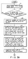
- step 31 in Fig. 3A an image photographed by imaging unit 17 is read.
- step 33 it is determined whether a detection signal is output from object detecting section 3. If NO is obtained, the flow returns to step 31. If YES in step 33, CCU 1 computes number S* e of pixels of the image area of the detected object in step 35.
- transformation from 2-dimensional plane data into 3-dimensional space date can be represented by: where X* - Y* - Z* - W* is a homogeneous coordinate system.
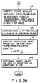
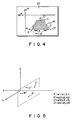
- step 37 the coordinate system (x* e - y* e ) of photographic image 23 is set as shown in Fig. 4, and minimum values y* e and x* e , and maximum values y* e and x* e of vehicle 19 and pedestrian 21 are respectively obtained.
- step 41 the area (I* e ) of rectangle A′B′C′D′ is computed.
- points A′, B′, C′, and D′ on photographic image 23 are transformed and the respective coordinates of points A′, B′, C′, and D′ in an arbitrary plane of a 3-dimensional space are obtained.
- points A′, B′, C′, and D′ on the image are transformed and corresponding points w1 (u1, v1), w2 (u2, v2), w3 (u3, v3), and w4 (u4, v4) in the arbitrary plane shown in Fig. 5 are computed.
- CCU 1 calculates the area (I) of rectangle w1, w2, w3, w4 in the arbitrary plane.
- CCU 1 discriminates the object on the basis of the projection area on the arbitrary plane.
- This processing is performed, for example, such that a standard projection area for each type of vehicle and a standard projection area of pedestrians are stored in RAM 11 and CCU 1 discriminates an object by comparing a calculated projection area with a projection area read out from RAM 11.
- Discrimination of an object may be performed by determining whether a projection area on an arbitrary plane of a 3-dimensional space exceeds a given threshold value or not. Upon comparison with a threshold value, even when only a vehicle or a pedestrian is photographed in a photographic image, the type of an obstacle can be discriminated.
- an object is detected by storing the density value of a road in advance and using it as a threshold value.
- an object may be detected by other known techniques, e.g., detecting horizontal edges in an image.
Abstract
An object sensor (15) outputs an obstacle detection signal in response to passing of an obstacle. A central control unit (CCU 1) reads a 2-dimensional image from an imaging unit (17) in response to the obstacle detection signal. A detection area is obtained by subtracting a background image prestored in a memory (11) from the input 2-dimensional image. The detected image on a 2-dimensional plane is transformed into image data in a 3-dimensional space. The CCU (1) computes the projection area of the image date on an arbitrary plane in the 3-dimensional space. The object is discriminated by comparing the computed projection area with the projection area based on the reference value of the object prestored in the memory (11).
Description
- The present invention relates to an object discriminating apparatus used for discrimination of vehicles, men, and the like for, e.g., automatic steering of vehicles, and a method therefor.
- In modern society, vehicles have become indispensable as a transportation means. However, many traffic accidents occur by careless driving. For this reason, the study of automatic steering of vehicles has been recently made from the viewpoint of prevention against traffic accidents.
- The study of automatic steering of vehicles is branched into various subjects. One of important subjects is concerned with detection and discrimination of an obstacle, wherein an obstacle is detected from a photographic image and the type of the obstacle is discriminated. As a conventional method of detecting an obstacle using a photographic image, a method of determining an object, which is crossing road boundaries on an image, to be an obstacle is known (32nd (first semiannual conference, 1986) National Conference Preliminary Reports 6N-8, pp. 1943 - 1944, Information Processing Society). According to another known method, a vehicle traveling ahead is determined by detecting horizontal edges in an image on the basis of the fact that the image of a vehicle includes a large number of horizontal edges compared with background image (Journal of the Information Processing Society (Japan), vol. 27, No. 7, pp. 663 - 690).
- In both the above-described methods, however, only an obstacle is detected, but the type of the obstacle cannot be discriminated.
- It is an object of the present invention to provide an object discriminating apparatus, which can detect an object from a photographic image and discriminate the type of the object, and a method therefor.
- In order to achieve the above object, there is provided an object discriminating apparatus comprising: image photographing means for photographing an image; object detecting means for detecting an object from the photographic image photographed by the image photographing means; area computing means for computing a projection area of the object detected by the object detecting means in an arbitrary plane of a 3-dimensional space; and object discriminating means for discriminating the object on the basis of the projection area computed by the area computing means.
- According to the present invention, a method of discriminating an object comprises the steps of: photographing an image; detecting an object from the photographic image, computing a projection area of the detected object in an arbitrary plane of a 3-dimensional space, and discriminating the object on the basis of the computed projection area.
- According to the object discriminating apparatus and the method therefor of the present invention, the projection area of an object in an arbitrary plane of a 3-dimensional space is computed from a photographic image. Therefore, even if a distance between a photographing position and an obstacle is changed, an actual area can always be calculated, and hence discrimination of an object can be reliably performed.
- This invention can be more fully understood from the following detailed description when taken in conjunction with the accompanying drawings, in which:
- Fig. 1 is a block diagram showing an object discriminating apparatus according to an embodiment of the present invention;
- Fig. 2 is a view illustrating a photographic image obtained by an imaging unit;
- Figs. 3A and 3B are flow charts showing processing of an object detecting section, an area computing section, and an object discriminating section in Fig. 1;
- Fig. 4 is a view for explaining a method computing the projection area of an object in an arbitrary plane of a 3-dimensional space using a photographic image;
- Fig. 5 is a view illustrating coordinate points A′, B′, C′, and D′ in a arbitrary plane of a 3-dimensional space when they are respectively set to be w₁ (u₁, v₁), W₂ (u₂, v₂),. w₃, (u₃, v₃), and w₄ (u₄, v₄); and
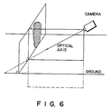
- Fig. 6 is a view illustrating the projection areas of a vehicle and a pedestrian in an arbitrary plane of a 3-dimensional space.
- Fig. 1 is a block diagram showing an object discriminating apparatus according to an embodiment of the present invention. Referring to Fig. 1, central control unit (CCU) 1 comprises
object detecting section 3,area computing section 5, and objectdiscriminating section 7.Imaging unit 17 is connected to CCU 1. Imagingunit 17 forms an image of a target visual field and outputs an image signal.Imaging unit 17 can be constituted by, e.g., an industrial television (ITV) camera such as an automatic focusing type of camera which is off the shelf. In addition, read-only memory (ROM) 9 for storing the program of the flow charts shown in Figs. 3A and 3B, and random access memory (RAM) 11 serving as a work area for performing various calculations are connected toCCU 1. CCU 1 can be constituted by, e.g., a microcomputer.CCU 1,ROM 9, andRAM 11 can be integrated into a one-chip microcomputer. - Fig. 2 shows an example of
image 23 photographed byimaging unit 17. In this embodiment,image 23 is constituted byvehicle 19 andpedestrian 21. - A case wherein
vehicle 19 andpedestrian 21 are discriminated inimage 23 by using the object discriminating apparatus of the present invention will be described below with reference to the flow charts in Figs. 3A and 3B. - In
step 31 in Fig. 3A, an image photographed byimaging unit 17 is read. Instep 33, it is determined whether a detection signal is output fromobject detecting section 3. If NO is obtained, the flow returns tostep 31. If YES instep 33,CCU 1 computes number S*e of pixels of the image area of the detected object instep 35. - Since
vehicle 19 andpedestrian 21 photographed byimaging unit 17 are transformed from 3-dimensional space data into 2-dimensional plane date, the 2-dimensional plane data must be perspectively transformed into the 3-dimensional space date. - If x* - y* is a coordinate system prior to the transformation, and x - y - z is a coordinate system after the transformation, transformation from 2-dimensional plane data into 3-dimensional space date can be represented by:

- Equations (1) and (2) are related to equations of transformation when a viewpoint is located at a position of z = h on the z-axis in a right-handed coordinate system. The position of Z = h represents a focal position of the ITV camera. Since a viewpoint is located on the origin in an eye coordinate system (xe - ye - ze), the related equations of transformation in the eye coordinate system can be represented by the following equations if x*e = y*e is a coordinate system prior to the transformation and X*e - Y*e - Z*e - w*e is a homogeneous coordinate system:

vehicle 19 andpedestrian 21 in an arbitrary plane of a 3-dimensional space can be obtained using equations (5) and (6) in the following procedure. Note that plane P is perpendicular to a plane including the optical axis of a camera shown in Fig. 6 and to a plane (ground) with which the object is in contact. - First, in step 37, the coordinate system (x*e - y*e) of
photographic image 23 is set as shown in Fig. 4, and minimum values y*e and x*e, and maximum values y*e and x*e ofvehicle 19 andpedestrian 21 are respectively obtained. Instep 39, point A′ satisfying (a₁, a₂-1) = (x*e1, y*e1), point B′ satisfying (b₁+1, b₂) = (x*e2, y*e2), point C′ satisfying (c₁, c₂+1) = (x*e3, y*e3, and point D′ satisfying (d₁-1, d₂) = x*e4, y*e4) are obtained. In addition, instep 41, the area (I*e) of rectangle A′B′C′D′ is computed. Area I*e of the rectangle having vertexes A′, B′, C′, and D′ can be given by:
I*e = | (1/2){(x*e2 - x*e1)(y*e2 + y*e1)
+ (x*e3 - x*e2)(y*e3 + y*e2)
+ (x*e4 - x*e3)(y*e4 + y*e3)
+ (x*e1 - x*e4)(y*e1 + y*e4)}| (7) - Subsequently, points A′, B′, C′, and D′ on
photographic image 23 are transformed and the respective coordinates of points A′, B′, C′, and D′ in an arbitrary plane of a 3-dimensional space are obtained. More specifically, instep 43, points A′, B′, C′, and D′ on the image are transformed and corresponding points w₁ (u₁, v₁), w₂ (u₂, v₂), w₃ (u₃, v₃), and w₄ (u₄, v₄) in the arbitrary plane shown in Fig. 5 are computed. In addition,CCU 1 calculates the area (I) of rectangle w₁, w₂, w₃, w₄ in the arbitrary plane. Area I of rectangle w₁, w₂, w₃, w₄ can be calculated by the following equation:
I = | (1/2){(u₂ - u₁)(v₂ + v₁)
+ (u₃ - u₂)(v₃ + v₂)
+ (u₄ - u₃)(v₄ + v₃)
+ (u₁ - u₄)(v₁ + v₄)}| (8)
In step 47, CCU 1 calculates the projection area of the object on an arbitrary plane by the following equations:
S = S*e·(I/I*e) (9)
- In
step 49,CCU 1 discriminates the object on the basis of the projection area on the arbitrary plane. This processing is performed, for example, such that a standard projection area for each type of vehicle and a standard projection area of pedestrians are stored inRAM 11 andCCU 1 discriminates an object by comparing a calculated projection area with a projection area read out fromRAM 11. Discrimination of an object may be performed by determining whether a projection area on an arbitrary plane of a 3-dimensional space exceeds a given threshold value or not. Upon comparison with a threshold value, even when only a vehicle or a pedestrian is photographed in a photographic image, the type of an obstacle can be discriminated. In the above-described embodiment, an object is detected by storing the density value of a road in advance and using it as a threshold value. However, an object may be detected by other known techniques, e.g., detecting horizontal edges in an image.
Claims (7)
1. An object discriminating apparatus, comprising:
image capturing means (17) for capturing an image;
object detecting means (3) for detecting an object from the image captured by said capturing means;
area computing means (5) for computing a projected area of the object detected by said object detecting means on an arbitrary plane of a 3-dimensional space where the object is located; and
object discriminating means (7) for discriminating the object on the basis of the projected area computed by said area computing means.
2. An apparatus according to claim 1, characterized in that said area computing means (5) transforms 2-dimensional plane data in an image area of the object detected by said object detecting means into 3-dimensional space data according to the following equations:

(where xe - ye - Ze is an eye coordinate system, x*e - y*e is a coordinate system prior to transformation, and X*e - Y*e - Z*e - w*e is a homogeneous coordinate system), obtains minimum and maximum y*e values, and minimum and maximum x*e values in the extracted image area, obtains area I*e of a rectangle in an image plane having points A′, B′, C′, and D′ as vertexes which are obtained by the following equation:
I*e =| (1/2){(x*e2 - x*e1)(y*e2 + y*e1)
+ (x*e3 - x*e2)(y*e3 + y*e2)
+ (x*e4 - x*e3)(y*e4 + y*e3)
+ (x*e1 - s*e4)(y*e1 + ye4)}| (4)
(where point A having the minimum y*e value is set as A = (a₁, a₂), point B having the maximum x*e value is set as B = (b₁, b₂), point C having the maximum y*e value is set as C = (c₁, c₂), and point D having the minimum x*e value is set as D = (d₁, d₂), and a point (a₁, a₂-1) is set as A′ = x*e1, y*e1), a point (b₁+1, b₂) is set as B′ = x*e2, y*e2), a point (c₁, c₂+1) is set as C′ = (x*e3, y*e3), a point (d₁-1, d₂) is set as D′= (x*e4, y*e4)), obtains area I of a rectangle having points w₁, w₂, w₃, and w₄, as vertexes using the following equation when each point of A′, B′, C′, and D′ projected on an arbitrary plane of a 3-dimensional space are respectively set to be w₁(u₁, v₁), w₂ (u₂, v₂), w₃ (u₃, v₃), and w₄ (u₄, v₄):
I = | (1/2){(u₂ - u₁)(v₂+ v₁)
+ (u₃ - u₂)(v₃+ v₂)
+ (u₄ - u₃)(v₄+ v₃)
+ (u₁ - u₄)(v₁ + v₄)}| (5)
and calculates a projected area of the detected object on the arbitrary plane of the 3-dimensional space using the following equation:
S = S*e·(I/I*e) (6)
where S*e is a number of pixels of an extracted image.
3. An apparatus according to claim 1, characterized in that said object discriminating means (7) comprises reference area value storing means for storing a reference value of an object to be discriminated, and discriminates the object by comparing the area obtained by said area computing means with the reference value read out from said reference area value storing means.
4. A method of discriminating an object, comprising the steps of:
capturing an image;
detecting an object from the captured image;
computing a projected area of the detected object on an arbitrary plane of a 3-dimensional space where the object is located; and
discriminating the object on the basis of the computed projection area.
capturing an image;
detecting an object from the captured image;
computing a projected area of the detected object on an arbitrary plane of a 3-dimensional space where the object is located; and
discriminating the object on the basis of the computed projection area.
5. A method according to claim 4, characterized in that the step of detecting the object comprises the steps of:
prestoring a background image, which is an image before the object is captured, in a memory; and
detecting existence of the object using a sensor, capturing an image including the object in response to an object detection signal from said sensor, and detecting the object by subtracting the background image prestored in said memory from the captured image.
6. A method according to claim 4, characterized in that the step of computing the area comprises the steps of transforming 2-dimensional plane data in an image area of the object detected by said object detecting means into 3-dimensional space data according to the following equations: 
(where xe - ye - ze is an eye coordinate system, x*e - y*e is a coordinate system prior to transformation, and X*e - Y*e - Z*e - w*e is a homogeneous coordinate system), obtaining minimum and maximum y*e values and minimum and maximum x*e values in the extracted image area, obtaining area I*e of a rectangle in 2-dimensional image data having points A′, B′, C′, and D′ as vertexes which are obtained by the following equation:
I*e =| (1/2){(x*e2 - x*e1)(y*e2 + y*e1)
+ (x*e3 - x*e2)(y*e3 + y*e2)
+ (x*e4 - x*e3)(y*e4 + y*e3)
+ (x*e1 - x*e4)(y*e1 + y*e4)} | (4)
(where point A having the minimum y*e value is set as A = (a₁, a₂), point B having the maximum x*e value is set as B = (b₁, b₂), point C having the maximum y*e value is set as C = (c₁, c₂), and point D having the minimum x*e value is set as D = (d₁, d₂), and a point (a₁, a₂-1) is set as A′ = (x*e1, y*e1), a point (b₁+1, b₂) is set as B′ = (x*e2, y*e2), a point (c₁, c₂+1) is set as C′ = (x*e3, y*e3), and a point (d₁-1, d₂) is set as D′ = (x*e4, y*e4)), obtaining area I of a rectangle having points w₁, w₂, w₃, and w₄ as vertexes using the following equation when each point of A′, B′, C′, and D' projected on an arbitrary plane of a 3-dimensional space are respectively set to be w₁ (u₁, v₁), w₂ (u₂, v₂), w₃ (u₃, v₃), and w₄ (u₄, v₄):
I =| (1/2){(u₂ - u₁)(v₂ + v₁)
+ (u₃ - u₂)(v₃ + v₂)
+ (u₄ - u₃)(u₄ + v₃)
+ (u₁ - u₄)(v₁ + v₄)}| (5)
and calculating a projected area of the detected object on the arbitrary plane of the 3-dimensional space using the following equation:
S = S*e·(I/I*e) (6)
where S*e is a number of pixels of an extracted image.
7. A method according to claim 4, characterized in that the step of discriminating the object comprises the steps of prestoring a reference value of the object to be discriminated in a reference area value memory, and comparing the area obtained by the step of computing the area with the reference value read out from said reference area value memory.
Applications Claiming Priority (2)
| Application Number | Priority Date | Filing Date | Title |
|---|---|---|---|
| JP203707/87 | 1987-08-17 | ||
| JP62203707A JPS6446875A (en) | 1987-08-17 | 1987-08-17 | Object discriminating device |
Publications (2)
| Publication Number | Publication Date |
|---|---|
| EP0304042A2 true EP0304042A2 (en) | 1989-02-22 |
| EP0304042A3 EP0304042A3 (en) | 1992-07-15 |
Family
ID=16478520
Family Applications (1)
| Application Number | Title | Priority Date | Filing Date |
|---|---|---|---|
| EP19880113372 Withdrawn EP0304042A3 (en) | 1987-08-17 | 1988-08-17 | Object discriminating apparatus and method therefor |
Country Status (4)
| Country | Link |
|---|---|
| US (1) | US5020114A (en) |
| EP (1) | EP0304042A3 (en) |
| JP (1) | JPS6446875A (en) |
| KR (1) | KR920001616B1 (en) |
Cited By (1)
| Publication number | Priority date | Publication date | Assignee | Title |
|---|---|---|---|---|
| EP0908846A2 (en) * | 1997-10-07 | 1999-04-14 | Canon Kabushiki Kaisha | Moving object detection apparatus and method |
Families Citing this family (36)
| Publication number | Priority date | Publication date | Assignee | Title |
|---|---|---|---|---|
| US5153721A (en) * | 1990-06-04 | 1992-10-06 | Olympus Optical Co., Ltd. | Method and apparatus for measuring an object by correlating displaced and simulated object images |
| US5903319A (en) * | 1991-05-13 | 1999-05-11 | Interactive Pictures Corporation | Method for eliminating temporal and spacial distortion from interlaced video signals |
| US5384588A (en) * | 1991-05-13 | 1995-01-24 | Telerobotics International, Inc. | System for omindirectional image viewing at a remote location without the transmission of control signals to select viewing parameters |
| US7714936B1 (en) | 1991-05-13 | 2010-05-11 | Sony Corporation | Omniview motionless camera orientation system |
| US6201574B1 (en) | 1991-05-13 | 2001-03-13 | Interactive Pictures Corporation | Motionless camera orientation system distortion correcting sensing element |
| US6243131B1 (en) | 1991-05-13 | 2001-06-05 | Interactive Pictures Corporation | Method for directly scanning a rectilinear imaging element using a non-linear scan |
| EP0664012B1 (en) * | 1992-10-07 | 1997-05-14 | Octrooibureau Kisch N.V. | Method and apparatus for classifying movement of objects along a passage |
| US5684937A (en) | 1992-12-14 | 1997-11-04 | Oxaal; Ford | Method and apparatus for performing perspective transformation on visible stimuli |
| US6731284B1 (en) | 1992-12-14 | 2004-05-04 | Ford Oxaal | Method of and apparatus for performing perspective transformation of visible stimuli |
| US6822563B2 (en) | 1997-09-22 | 2004-11-23 | Donnelly Corporation | Vehicle imaging system with accessory control |
| US5877897A (en) | 1993-02-26 | 1999-03-02 | Donnelly Corporation | Automatic rearview mirror, vehicle lighting control and vehicle interior monitoring system using a photosensor array |
| US5483168A (en) * | 1993-03-01 | 1996-01-09 | The United States Of America As Represented By The Administrator Of The National Aeronautics And Space Administration | Optical potential field mapping system |
| US6891563B2 (en) | 1996-05-22 | 2005-05-10 | Donnelly Corporation | Vehicular vision system |
| US7655894B2 (en) | 1996-03-25 | 2010-02-02 | Donnelly Corporation | Vehicular image sensing system |
| US6459451B2 (en) | 1996-06-24 | 2002-10-01 | Be Here Corporation | Method and apparatus for a panoramic camera to capture a 360 degree image |
| US6373642B1 (en) | 1996-06-24 | 2002-04-16 | Be Here Corporation | Panoramic imaging arrangement |
| US6331869B1 (en) | 1998-08-07 | 2001-12-18 | Be Here Corporation | Method and apparatus for electronically distributing motion panoramic images |
| US6341044B1 (en) | 1996-06-24 | 2002-01-22 | Be Here Corporation | Panoramic imaging arrangement |
| US6493032B1 (en) | 1996-06-24 | 2002-12-10 | Be Here Corporation | Imaging arrangement which allows for capturing an image of a view at different resolutions |
| US6356296B1 (en) | 1997-05-08 | 2002-03-12 | Behere Corporation | Method and apparatus for implementing a panoptic camera system |
| US6466254B1 (en) | 1997-05-08 | 2002-10-15 | Be Here Corporation | Method and apparatus for electronically distributing motion panoramic images |
| US6924832B1 (en) | 1998-08-07 | 2005-08-02 | Be Here Corporation | Method, apparatus & computer program product for tracking objects in a warped video image |
| US6369818B1 (en) | 1998-11-25 | 2002-04-09 | Be Here Corporation | Method, apparatus and computer program product for generating perspective corrected data from warped information |
| US6175454B1 (en) | 1999-01-13 | 2001-01-16 | Behere Corporation | Panoramic imaging arrangement |
| US20020147991A1 (en) * | 2001-04-10 | 2002-10-10 | Furlan John L. W. | Transmission of panoramic video via existing video infrastructure |
| JP2002334322A (en) * | 2001-05-10 | 2002-11-22 | Sharp Corp | System, method and program for perspective projection image generation, and storage medium stored with perspective projection image generating program |
| EP1504276B1 (en) | 2002-05-03 | 2012-08-08 | Donnelly Corporation | Object detection system for vehicle |
| JP3895238B2 (en) * | 2002-08-28 | 2007-03-22 | 株式会社東芝 | Obstacle detection apparatus and method |
| US7684624B2 (en) * | 2003-03-03 | 2010-03-23 | Smart Technologies Ulc | System and method for capturing images of a target area on which information is recorded |
| US7526103B2 (en) | 2004-04-15 | 2009-04-28 | Donnelly Corporation | Imaging system for vehicle |
| EP2784722A1 (en) * | 2004-07-26 | 2014-10-01 | Automotive Systems Laboratory, Inc. | Vulnerable road user protection system |
| US7881496B2 (en) | 2004-09-30 | 2011-02-01 | Donnelly Corporation | Vision system for vehicle |
| US20070152157A1 (en) * | 2005-11-04 | 2007-07-05 | Raydon Corporation | Simulation arena entity tracking system |
| US7972045B2 (en) | 2006-08-11 | 2011-07-05 | Donnelly Corporation | Automatic headlamp control system |
| US20080306708A1 (en) * | 2007-06-05 | 2008-12-11 | Raydon Corporation | System and method for orientation and location calibration for image sensors |
| US20170206430A1 (en) * | 2016-01-19 | 2017-07-20 | Pablo Abad | Method and system for object detection |
Citations (2)
| Publication number | Priority date | Publication date | Assignee | Title |
|---|---|---|---|---|
| JPS5941089A (en) * | 1982-08-31 | 1984-03-07 | Mitsubishi Electric Corp | Normalizing device of character pattern |
| US4646354A (en) * | 1983-10-26 | 1987-02-24 | Mitsubishi Denki Kabushiki Kaisha | Area measuring apparatus using television |
Family Cites Families (3)
| Publication number | Priority date | Publication date | Assignee | Title |
|---|---|---|---|---|
| GB1537322A (en) * | 1975-01-30 | 1978-12-29 | Agency Ind Science Techn | Apparatus for recognition of approximate shape of an article |
| DE3584642D1 (en) * | 1984-04-17 | 1991-12-19 | Kawasaki Heavy Ind Ltd | DEVICE FOR GENERATING A THREE-DIMENSIONAL COPY OF AN OBJECT. |
| JPH0681275B2 (en) * | 1985-04-03 | 1994-10-12 | ソニー株式会社 | Image converter |
-
1987
- 1987-08-17 JP JP62203707A patent/JPS6446875A/en active Pending
-
1988
- 1988-08-17 US US07/233,128 patent/US5020114A/en not_active Expired - Fee Related
- 1988-08-17 EP EP19880113372 patent/EP0304042A3/en not_active Withdrawn
- 1988-08-17 KR KR1019880010422A patent/KR920001616B1/en not_active IP Right Cessation
Patent Citations (2)
| Publication number | Priority date | Publication date | Assignee | Title |
|---|---|---|---|---|
| JPS5941089A (en) * | 1982-08-31 | 1984-03-07 | Mitsubishi Electric Corp | Normalizing device of character pattern |
| US4646354A (en) * | 1983-10-26 | 1987-02-24 | Mitsubishi Denki Kabushiki Kaisha | Area measuring apparatus using television |
Non-Patent Citations (2)
| Title |
|---|
| PATENT ABSTRACTS OF JAPAN vol. 8, no. 144 (P-284)(1581) 5 July 1984 & JP-A-59 041 089 ( MITSUBISHI DENKI K.K. ) 7 March 1984 * |
| W.M. NEWMAN ET AL. 'Principles of interactive computer graphics, 2nd edition' 1981 , MCGRAW-HILL INT. BOOK COMPANY , TOKYO, JP * |
Cited By (2)
| Publication number | Priority date | Publication date | Assignee | Title |
|---|---|---|---|---|
| EP0908846A2 (en) * | 1997-10-07 | 1999-04-14 | Canon Kabushiki Kaisha | Moving object detection apparatus and method |
| EP0908846A3 (en) * | 1997-10-07 | 2000-03-29 | Canon Kabushiki Kaisha | Moving object detection apparatus and method |
Also Published As
| Publication number | Publication date |
|---|---|
| KR920001616B1 (en) | 1992-02-20 |
| JPS6446875A (en) | 1989-02-21 |
| EP0304042A3 (en) | 1992-07-15 |
| KR890004245A (en) | 1989-04-20 |
| US5020114A (en) | 1991-05-28 |
Similar Documents
| Publication | Publication Date | Title |
|---|---|---|
| EP0304042A2 (en) | Object discriminating apparatus and method therefor | |
| US6734787B2 (en) | Apparatus and method of recognizing vehicle travelling behind | |
| JP5421072B2 (en) | Approaching object detection system | |
| JP3064928B2 (en) | Subject extraction method | |
| US10776637B2 (en) | Image processing device, object recognizing device, device control system, image processing method, and computer-readable medium | |
| EP1553516A2 (en) | Pedestrian extracting apparatus | |
| KR19980018699A (en) | Distance measuring device | |
| JP2000357233A (en) | Body recognition device | |
| JP6941070B2 (en) | Stereo camera device | |
| US10546383B2 (en) | Image processing device, object recognizing device, device control system, image processing method, and computer-readable medium | |
| US10733464B2 (en) | Method, system and device of obtaining 3D-information of objects | |
| US20180204345A1 (en) | Image processing device, object recognition device, device control system, image processing method and computer-readable medium | |
| KR20170088692A (en) | Device and Method for Calculating Vehicle Speed by Image | |
| JP2927916B2 (en) | Distance detection device | |
| JPH08136237A (en) | Device for calculating gradient of road and car speed controller | |
| KR101720679B1 (en) | Lane recognition system using light fied camera and method therefor | |
| JP4425852B2 (en) | Vehicle periphery monitoring device | |
| JPH0552562A (en) | Vehicular gap detector for tracking advance vehicle | |
| JP3605955B2 (en) | Vehicle identification device | |
| JPH0771916A (en) | On-vehicle distance measuring device | |
| JP4788399B2 (en) | Pedestrian detection method, apparatus, and program | |
| JP3447461B2 (en) | Moving obstacle detecting apparatus and method | |
| JP3530803B2 (en) | Vehicle detection device | |
| JP2002008019A (en) | Railway track recognition device and rolling stock using railway track recognition device | |
| JP2005092516A (en) | On-vehicle device for detecting moving object |
Legal Events
| Date | Code | Title | Description |
|---|---|---|---|
| PUAI | Public reference made under article 153(3) epc to a published international application that has entered the european phase |
Free format text: ORIGINAL CODE: 0009012 |
|
| 17P | Request for examination filed |
Effective date: 19880914 |
|
| AK | Designated contracting states |
Kind code of ref document: A2 Designated state(s): DE FR GB |
|
| PUAL | Search report despatched |
Free format text: ORIGINAL CODE: 0009013 |
|
| AK | Designated contracting states |
Kind code of ref document: A3 Designated state(s): DE FR GB |
|
| STAA | Information on the status of an ep patent application or granted ep patent |
Free format text: STATUS: THE APPLICATION HAS BEEN WITHDRAWN |
|
| 18W | Application withdrawn |
Withdrawal date: 19920813 |