EP0302415A2 - Image forming apparatus having device for detecting concentration of developing agent - Google Patents
Image forming apparatus having device for detecting concentration of developing agent Download PDFInfo
- Publication number
- EP0302415A2 EP0302415A2 EP88112374A EP88112374A EP0302415A2 EP 0302415 A2 EP0302415 A2 EP 0302415A2 EP 88112374 A EP88112374 A EP 88112374A EP 88112374 A EP88112374 A EP 88112374A EP 0302415 A2 EP0302415 A2 EP 0302415A2
- Authority
- EP
- European Patent Office
- Prior art keywords
- developing
- data
- concentration
- identification data
- developing agent
- Prior art date
- Legal status (The legal status is an assumption and is not a legal conclusion. Google has not performed a legal analysis and makes no representation as to the accuracy of the status listed.)
- Granted
Links
Images


Classifications
-
- G—PHYSICS
- G03—PHOTOGRAPHY; CINEMATOGRAPHY; ANALOGOUS TECHNIQUES USING WAVES OTHER THAN OPTICAL WAVES; ELECTROGRAPHY; HOLOGRAPHY
- G03G—ELECTROGRAPHY; ELECTROPHOTOGRAPHY; MAGNETOGRAPHY
- G03G21/00—Arrangements not provided for by groups G03G13/00 - G03G19/00, e.g. cleaning, elimination of residual charge
- G03G21/16—Mechanical means for facilitating the maintenance of the apparatus, e.g. modular arrangements
- G03G21/18—Mechanical means for facilitating the maintenance of the apparatus, e.g. modular arrangements using a processing cartridge, whereby the process cartridge comprises at least two image processing means in a single unit
- G03G21/1875—Mechanical means for facilitating the maintenance of the apparatus, e.g. modular arrangements using a processing cartridge, whereby the process cartridge comprises at least two image processing means in a single unit provided with identifying means or means for storing process- or use parameters, e.g. lifetime of the cartridge
- G03G21/1878—Electronically readable memory
- G03G21/1889—Electronically readable memory for auto-setting of process parameters, lifetime, usage
-
- G—PHYSICS
- G03—PHOTOGRAPHY; CINEMATOGRAPHY; ANALOGOUS TECHNIQUES USING WAVES OTHER THAN OPTICAL WAVES; ELECTROGRAPHY; HOLOGRAPHY
- G03G—ELECTROGRAPHY; ELECTROPHOTOGRAPHY; MAGNETOGRAPHY
- G03G15/00—Apparatus for electrographic processes using a charge pattern
- G03G15/06—Apparatus for electrographic processes using a charge pattern for developing
- G03G15/08—Apparatus for electrographic processes using a charge pattern for developing using a solid developer, e.g. powder developer
- G03G15/0822—Arrangements for preparing, mixing, supplying or dispensing developer
- G03G15/0848—Arrangements for testing or measuring developer properties or quality, e.g. charge, size, flowability
- G03G15/0849—Detection or control means for the developer concentration
-
- G—PHYSICS
- G03—PHOTOGRAPHY; CINEMATOGRAPHY; ANALOGOUS TECHNIQUES USING WAVES OTHER THAN OPTICAL WAVES; ELECTROGRAPHY; HOLOGRAPHY
- G03G—ELECTROGRAPHY; ELECTROPHOTOGRAPHY; MAGNETOGRAPHY
- G03G15/00—Apparatus for electrographic processes using a charge pattern
- G03G15/06—Apparatus for electrographic processes using a charge pattern for developing
- G03G15/08—Apparatus for electrographic processes using a charge pattern for developing using a solid developer, e.g. powder developer
- G03G15/0822—Arrangements for preparing, mixing, supplying or dispensing developer
- G03G15/0863—Arrangements for preparing, mixing, supplying or dispensing developer provided with identifying means or means for storing process- or use parameters, e.g. an electronic memory
-
- G—PHYSICS
- G03—PHOTOGRAPHY; CINEMATOGRAPHY; ANALOGOUS TECHNIQUES USING WAVES OTHER THAN OPTICAL WAVES; ELECTROGRAPHY; HOLOGRAPHY
- G03G—ELECTROGRAPHY; ELECTROPHOTOGRAPHY; MAGNETOGRAPHY
- G03G15/00—Apparatus for electrographic processes using a charge pattern
- G03G15/06—Apparatus for electrographic processes using a charge pattern for developing
- G03G15/08—Apparatus for electrographic processes using a charge pattern for developing using a solid developer, e.g. powder developer
- G03G15/0822—Arrangements for preparing, mixing, supplying or dispensing developer
- G03G15/0887—Arrangements for conveying and conditioning developer in the developing unit, e.g. agitating, removing impurities or humidity
- G03G15/0891—Arrangements for conveying and conditioning developer in the developing unit, e.g. agitating, removing impurities or humidity for conveying or circulating developer, e.g. augers
- G03G15/0893—Arrangements for conveying and conditioning developer in the developing unit, e.g. agitating, removing impurities or humidity for conveying or circulating developer, e.g. augers in a closed loop within the sump of the developing device
-
- G—PHYSICS
- G03—PHOTOGRAPHY; CINEMATOGRAPHY; ANALOGOUS TECHNIQUES USING WAVES OTHER THAN OPTICAL WAVES; ELECTROGRAPHY; HOLOGRAPHY
- G03G—ELECTROGRAPHY; ELECTROPHOTOGRAPHY; MAGNETOGRAPHY
- G03G15/00—Apparatus for electrographic processes using a charge pattern
- G03G15/06—Apparatus for electrographic processes using a charge pattern for developing
- G03G15/08—Apparatus for electrographic processes using a charge pattern for developing using a solid developer, e.g. powder developer
- G03G15/0896—Arrangements or disposition of the complete developer unit or parts thereof not provided for by groups G03G15/08 - G03G15/0894
-
- G—PHYSICS
- G03—PHOTOGRAPHY; CINEMATOGRAPHY; ANALOGOUS TECHNIQUES USING WAVES OTHER THAN OPTICAL WAVES; ELECTROGRAPHY; HOLOGRAPHY
- G03G—ELECTROGRAPHY; ELECTROPHOTOGRAPHY; MAGNETOGRAPHY
- G03G21/00—Arrangements not provided for by groups G03G13/00 - G03G19/00, e.g. cleaning, elimination of residual charge
- G03G21/16—Mechanical means for facilitating the maintenance of the apparatus, e.g. modular arrangements
- G03G21/1604—Arrangement or disposition of the entire apparatus
- G03G21/1623—Means to access the interior of the apparatus
-
- G—PHYSICS
- G03—PHOTOGRAPHY; CINEMATOGRAPHY; ANALOGOUS TECHNIQUES USING WAVES OTHER THAN OPTICAL WAVES; ELECTROGRAPHY; HOLOGRAPHY
- G03G—ELECTROGRAPHY; ELECTROPHOTOGRAPHY; MAGNETOGRAPHY
- G03G2221/00—Processes not provided for by group G03G2215/00, e.g. cleaning or residual charge elimination
- G03G2221/16—Mechanical means for facilitating the maintenance of the apparatus, e.g. modular arrangements and complete machine concepts
- G03G2221/1663—Mechanical means for facilitating the maintenance of the apparatus, e.g. modular arrangements and complete machine concepts having lifetime indicators
-
- G—PHYSICS
- G03—PHOTOGRAPHY; CINEMATOGRAPHY; ANALOGOUS TECHNIQUES USING WAVES OTHER THAN OPTICAL WAVES; ELECTROGRAPHY; HOLOGRAPHY
- G03G—ELECTROGRAPHY; ELECTROPHOTOGRAPHY; MAGNETOGRAPHY
- G03G2221/00—Processes not provided for by group G03G2215/00, e.g. cleaning or residual charge elimination
- G03G2221/16—Mechanical means for facilitating the maintenance of the apparatus, e.g. modular arrangements and complete machine concepts
- G03G2221/18—Cartridge systems
- G03G2221/183—Process cartridge
- G03G2221/1838—Autosetting of process parameters
-
- G—PHYSICS
- G03—PHOTOGRAPHY; CINEMATOGRAPHY; ANALOGOUS TECHNIQUES USING WAVES OTHER THAN OPTICAL WAVES; ELECTROGRAPHY; HOLOGRAPHY
- G03G—ELECTROGRAPHY; ELECTROPHOTOGRAPHY; MAGNETOGRAPHY
- G03G2221/00—Processes not provided for by group G03G2215/00, e.g. cleaning or residual charge elimination
- G03G2221/16—Mechanical means for facilitating the maintenance of the apparatus, e.g. modular arrangements and complete machine concepts
- G03G2221/18—Cartridge systems
- G03G2221/183—Process cartridge
- G03G2221/1853—Process cartridge having a submodular arrangement
- G03G2221/1869—Cartridge holders, e.g. intermediate frames for placing cartridge parts therein
Definitions
- the present invention relates to an image forming apparatus having a device for detecting the concentration of a developing agent stored therein and, more particularly, to an image forming apparatus such as a laser printer or an electronic copying machine into which a developing unit can be detachably mounted.
- a device for detecting the concentration of the developing agent is initialized with reference to a developing agent concentration at the time of shipping or the like. That is, at the time of shipping, the reference developing agent concentration is converted into a reference voltage signal, and this signal is permanently stored as a reference voltage value in the developing unit body. After shipping, when the actual developing agent concentration becomes lower than the reference concentration, the decrease in concentration is detected by the device for detecting the concentration of the developing agent.
- the device generates a detection signal having a high voltage value. When the detection signal exceeds a predetermined voltage level, a toner is replenished from a toner hopper to a stirrer. The toner is stirred by the stirrer. When the concentration of the developing agent in the stirrer reaches the reference value, replenishment of the toner is stopped.
- the detection signal level of the developing unit at the time of shipping is given as a reference, thereby controlling the developing agent concentration of the new developing unit.
- developing units are manufactured as single units, the relationships between the voltage levels of detection signals from concentration detecting devices and the developing agent densities vary depending on different developing units.
- developing units having different detection characteristics are controlled on the basis of a reference value permanently stored in an image developing apparatus, the developing agent concentration varies whenever the developing unit is replaced with a new one. Therefore, the developing units cannot be optimally controlled depending on the characteristics of the individual developing units.
- the reference developing agent concentration cannot always be maintained to be the reference developing agent concentration in the stirrer.
- the quality of the image formed by the image forming apparatus may be degraded. That is, even if the concentration of the developing agent is decreased, the voltage level of the detection signal generated by the concentration detecting device is not increased and the level of the detection signal does not reach the voltage level corresponding to replenishment. Therefore, the toner is not replenished, and the concentration of the developing agent in the developing unit is kept low. As a result, an image having a very low concentration is formed, thus degrading image quality.
- the toner When the detection signal from the concentration detecting device is kept at a level equal to or higher than the reference level, the toner is supplied to increase the developing agent concentration in the developing unit. An image having an excessively high concentration is formed, and image quality is therefore degraded.
- an image forming apparatus comprising: means for forming a latent image; means for developing the latent image with a developing agent having a concentration varying as the developing of the latent image proceeds, the developing means having an identification data corresponding to the developing means: data-generating means for generating first concentration data representing the concentration before the latent image is developed, and also second concentration data representing the concentration varied for developing the latent image; comparing-storing means for comparing the identification data with a reference identification data before the latent image is developed, and for storing the identification data as a new reference identification data and also storing first concentration data as a new reference concentration data which is generated from the data-generating means and corresponds to the new reference identification data when the identification data is different from the reference identification data; and means for supplying the developing agent to the forming means in order to coincide the second concentration data with the reference concentration data corresponding to the identification data when the identification data is identical to the reference identification data stored in the comparing-storing means.
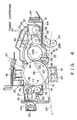
- Figs. 1 and 2 are a perspective view and a schematic longitudinal sectional view of a laser printer as an image forming apparatus according to an embodiment of the present invention.
- Reference numeral 1 in Figs. 1 and 2 denotes a laser printer as the image forming apparatus.
- the rear portion of the upper surface of printer body 5 is stepped upward, and recess 6 serving as a discharge portion of printer body 5 is formed at the central portion of the upper surface.
- Exhaust tray 8 which is movably supported by jogger 7 is mounted in recess 6.
- Console panel display unit 9 serving as an operation panel and console panel switch unit 10 serving as an input means are arranged to the right of recess 6.
- Three IC card insertion ports 11 are formed to the left of recess 6.
- Console panel display unit 9 includes LCD (Liquid Crystal Display) unit 9a for displaying setting conditions of the apparatus, and display unit 9b for indicating operating states with LEDs (Light-Emitting Diodes), as shown in Fig. 3A.
- a copy count or a copy mode is displayed on display unit 9a.
- Display unit 9b indicates a mode for representing whether the apparatus is connected to an external device (ON/OFF line mode), a print ready mode, a printing data transfer mode, an operator call mode, a service man call mode, and a manual reference mode.
- Console panel switch unit 10 includes ten-key pad 10a, ON/OFF line selection key 10b, clear key 10c, YES key 10d, NO key 10e, and EXIT key 10f, as shown in Fig. 4B.
- Keys of ten-key pad 10a are used to set a copy count mode, a paper source feed mode, a printing stop/paper exhaust mode, and the like.
- Clear key 10c also serves as a reset key.
- YES key 10d also serves as an enter key.
- NO key 10e also serves as a NEXT key and an INCREMENT KEY.
- Exit key 10f also serves as an ESC key and a DECREMENT key.
- Exhaust tray 12 is mounted on the front surface of printer body 5, as shown in Fig. 1.
- Manual feed tray 13 is mounted on the rear surface side.
- Photosensitive drum 15 serving as an image carrier is disposed at substantially the center of printer body 5.
- Charger 16, laser optical system 17, developing unit 18 serving as a developing means, transfer unit 19, separating unit 20, cleaner unit 21 serving as a cleaner means, and discharger 22 are sequentially arranged around photosensitive drum 15, as shown in Fig. 5.
- Convey path 24 extending toward the exhaust side through image transfer section 23 between photosensitive drum 15 and transfer unit 19 is formed in printer body 5.
- Paper feed roller 28 and paper transfer roller 29 are arranged such that sheet P automatically fed from paper cassette 25 mounted at the bottom portion of printer body 5 through paper feed roller 28 and paper transfer roller 29 or paper sheet P manually fed from manual feed tray 13 is guided to image transfer unit 23.
- Aligning roller pair 30 is arranged on the upstream side of image transfer section 23 in convey path 24.
- Fixing unit 31, exhaust selector 32, and exhaust roller pair 33 are located on the downstream of image transfer section 23.
- branch convey path 35 with exhaust roller pair 34 is formed to guide sheet P selected by exhaust selector 32 to recess 6 serving as the exhaust section.
- reference numeral 40 denotes a lower cover; 41, a front cover; 42, an upper cover; 43, an openable right cover (door); 44, a left cover; 45, a right cover opening/closing lever; and 46, an upper unit opening/closing lever.
- reference numerals 47, 48, and 49 denote control boards constituting a controller.
- the above laser printer is operated in the following manner to form an image.
- photosensitive drum 15 is rotated and is uniformly charged by charger 16.
- the charged surface of photosensitive drum 15 is exposed by a laser beam guided by laser optical system 17 and generated in accordance with an image signal, thereby forming a latent image thereon.
- the latent image on photosensitive drum 15 is developed by developing unit 18 using two-component developing agent D consisting of a toner and a carrier.
- the latent image is thus converted into a visible image.
- the image is then fed to the image transfer section 23 in which the image is transferred onto a sheet.
- sheet P is picked up from paper cassette 25 or sheet P is manually fed.
- Sheet P is fed to aligning roller pair 30, and the developing agent image formed on photosensitive drum 15 is transferred to sheet P by transfer unit 19.
- Sheet P is then separated from photosensitive drum 15 by separating unit 20 and is fed to fixing unit 31 through convey path 24.
- the exhaust direction of sheet P is selected by selector 32, so that sheet P is exhausted into upper exhaust tray 8 or front exhaust tray 12.
- the residual toner on photosensitive drum 15 is cleaned by cleaning unit 21, and photosensitive drum 15 is ready for the next copying cycle.
- cleaning unit 21 for cleaning photosensitive drum 15 comprises shaft 201 extending along the central axis of developing roller 59. Both ends of handle 87 are pivotally supported by corresponding ends of shaft 201. When handle 87 is inclined in guide frame 51 and is fitted therein, as shown in Fig. 5, cleaning unit 21 can be accurately fitted in guide frame 51.
- developing unit 18 for developing the latent image on photosensitive body 15 comprises shaft 202 for photosensitive drum 15, as shown in Fig. 7. Both ends of handle 88 are pivotally mounted on corresponding ends of shaft 202.
- developing unit 18 can be mounted in guide frame 51.
- Guide frame 51 is slidably supported by slide rails 50. As shown in Fig.
- guide frame 51 is pulled together with developing unit 18 and cleaning unit 21 along slide rails 50 while right cover 43 of printer body 5 is kept open. Similarly, guide frame 51 can be loaded together with developing unit 18 and cleaning unit 21 into body 5 along slide rails 50.
- handle 87 or 88 can be moved from guide frame 51, as shown in Figs. 6 and 7, so that developing unit 18 or cleaning unit 21 can be removed outside guide frame 51. That is, photosensitive drum 15 and cleaning unit 21 are independent units, so that photosensitive drum 15 and cleaning unit 21 can be removed from guide frame 51 together or separately. At least developing unit 18 can be horizontally held in printer body 5 by guide frame 51.
- Developing unit 18 comprises developing mechanism 55 and developing agent stirring section 56, as shown in Fig. 5.
- developing mechanism 55 developing roller 59 is disposed to oppose opening 58 of developing unit body 57.
- Developing agent magnetic brush Da is formed on the surface of developing roller 59.
- Doctor blade 61 is disposed on the upstream side developing section 60 on the convey path of developing agent magnetic brush Da to control the thickness of developing agent magnetic brush Da supplied to a sliding portion between developing agent magnetic brush Da and photosensitive drum 15 or to developing section 60.
- Scraper 62 is disposed on the downstream side developing section 60 on the convey path of developing agent magnetic brush Da.
- Developing agent magnetic brush Da formed on the surface of developing roller 59 is separated by scraper 62 and is guided to developing agent stirring section 56.
- Stirring section 56 includes developing agent storage section 63 formed behind developing roller 59 with respect to photosensitive drum 15.
- First and second stirring members 64 and 65 serving as developing agent convey augers, shown in Fig. 8, are disposed in developing agent storage section 63.
- Developing roller 59 comprises magnetic roll 59a having a plurality of pole pieces and nonmagnetic sleeve 59b fitted on magnetic roll 59a and rotatable clockwise.
- toner reception section 66 is formed to oppose developing agent stirring section 56 in developing unit body 57 to receive the developing agent therein.
- the toner replenished from toner cartridge 67 for replenishing the developing agent and the toner returning from cleaning unit 21 through return path 68 for returning the developing agent are received in developing agent stirring section 56 through reception section 66.
- Developing agent concentration sensor 70 is arranged to oppose scraper 62 to detect the concentration of the developing agent.
- a toner replenishment shaft (not shown) built into toner cartridge 67 is driven independently of printer body 5 in response to the detection signal from developing agent concentration sensor 70, thereby supplying the toner to developing agent stirring section 56.
- Particles of developing agent D are attracted by the lines of magnetic force generated by the respective pole pieces to form magnetic brush Da on the surface of nonmagnetic sleeve 59b.
- Developing agent magnetic brush Da is continuously conveyed to developing section 60 upon rotation of sleeve 59b.
- the toner particles in magnetic brush Da are attracted to the latent image on photosensitive drum 15, so that the latent image is developed.
- developing agent stirring members 64 and 65 disposed in developing agent storage section 63 developing agent D is stirred to bring the toner and carrier into frictional contact with each other. Therefore, the toner can be effectively charged.
- Developing agent D is conveyed while being stirred by stirring members 64 and 65 in developing agent storage section 63. More specifically, the toner replenished from toner replenishing port 66 is fed to the stirring member 64 side by flat U-turn blade 204a and is immediately conveyed by convey blade 205. The toner is sufficiently stirred by stirring blade 69 arranged midway along the shaft. The toner is then fed to the stirring member 65 side by flat U-turn blade 204b. Thereafter, the flow of developing agent D is changed by small blade 74 located at the center of the shaft along its axial direction. By utilizing the change in flow, the concentration of the developing agent is detected (to be described later).
- Developing agent stirring members 64 and 65 are horizontally arranged in developing unit 18 so as to eliminate an adverse influence of conveyance of developing agent D, i.e., prevent a convey failure.
- a stirring blade is not formed at a developing agent stirring member 64 portion corresponding to toner reception section 66 in order to prevent delay of toner detection and toner clogging. Only the convey blade is formed at this portion.
- developing unit 18 has board 39B having identification signal generator 39A for generating an identification signal for designating the developing unit, i.e., old and new developing units, and manufacturing no. of the developing unit, and sensor 70 for detecting the concentration of the developing agent.
- identification signal generator 39A for generating an identification signal for designating the developing unit, i.e., old and new developing units, and manufacturing no. of the developing unit
- sensor 70 for detecting the concentration of the developing agent.
- a detection signal from sensor 70 is converted into a voltage signal.
- This voltage signal is stored as an initial voltage signal, e.g., a reference voltage signal corresponding to the reference concentration in a memory, e.g.. nonvolatile memory 122 in printer body 5 shown in Fig. 11.
- Concentration control of developing unit 18 is started on the basis of the stored voltage value. Refer to USP 369,826 for concentration sensor 70 and a method of detecting the concentration of the developing agent with sensor 70.
- Cleaning unit 21 comprises case 75 having opening 76 opposite to photosensitive drum 15, as shown in Fig. 5.
- Cleaning blade 77 is arranged in case 75 of the cleaning unit.
- the upper end portion of cleaning blade 77 is fixed to blade holder 80 such that blade 77 is pivotal about shaft 78 and always biased counterclockwise by counterweight 79 in a state shown in Fig. 4.
- the lower end portion of cleaning blade 77 is urged against the outer surface of photosensitive drum 15. After the toner is transferred from photosensitive drum 15 to the sheet, the toner left on photosensitive drum 15 and reaching cleaning blade 77 is removed by cleaning blade 77.
- Recovery blade 81 is mounted at the lower edge of opening 76. Recovery blade 81 recovers the toner removed by cleaning blade 77 into cleaning unit case 75. Toner recovery auger 82 is arranged at the bottom portion of case 75 to transfer the recovered toner to return path 68.
- CPU 120 for controlling the operation of the overall printer system is connected to input and output ports 124 and 126, A/D converter 127, ROM 121 for storing control programs, and memory 122 comprised of a nonvolatile RAM through data bus 128.
- Memory 122 stores an identification number (i.e., confidential number) for identifying developing unit 19 which is identified during data updating, a count, a reference voltage signal, and sheet data (e.g., top margin, left margin, and type of paper).
- a control program is supplied from ROM 121 to CPU 120 through input port 124 on the basis of a command from console panel switch 10.
- Print data is supplied from an external device to CPU 120 through the input port and is processed.
- An operation command is supplied to console panel display unit 9, driver 125 for driving a toner supply mechanism, and driver 123 for driving the developing unit through output port 126.
- Drivers 123 and 125 are driven to operate the respective parts of the printer, as described above, thereby printing information on the sheet.
- concentration of the developing agent in developing unit 18 is detected by concentration sensor 70.
- a detection signal from sensor 70 is converted into a digital signal by A/D converter 127 controlled by a control signal from the output port.
- the digital signal is compared with the reference concentration of developing unit 18 which is stored in memory 122 by CPU 120. If the detected concentration is lower than the reference concentration, driver 125 is driven in accordance with the command from CPU 120, and the toner is supplied from toner cartridge 67 to developing unit 18. When the concentration of the toner of the developing agent in developing unit 18 reaches the reference concentration, driver 125 is deenergized by the command from CPU 120. Supply of the toner from toner cartridge 67 to developing unit 18 is stopped.
- the data representing the number of prints and stored in memory 122 is updated upon every printing.
- CPU 120 When the number of prints reaches a predetermined number, CPU 120 generates a command for designating replacement of the developing unit to console panel display unit 9 since the service life of developing unit 18 is ended.
- Display unit 9 displays need for replacement of the developing unit in accordance with this command. An operator observes this display and turns off the power of the printer system. As described with reference to Figs. 6 and 7, developing unit 18 and cleaning unit 21 are replaced with new ones, respectively.
- the switch is turned on again.
- the drive system In response to power-on operation, the drive system is warmed up in accordance with the command from CPU 120 in step 203.
- a heater is energized, a main motor is turned on, the start of the mirror motor is checked, and developing agent D in new developing unit 18 is stirred.
- An identification signal of developing unit 18 which is generated by identification signal generator 39A is supplied to CPU 120 and is compared with that of old developing unit 18 which is already stored in memory 122 in step 204.
- identification number data in memory 122 is not updated, and the printer is kept in the standby mode.
- developing unit 18 is replaced with a new one and the two identification numbers do not coincide with each other, developing unit 18 is determined to be a new one.
- the developing agent in developing unit 18 is sufficiently (e.g., for two minutes) stirred.
- concentration of the toner in the developing agent is detected by sensor 70 in step 206.
- a detection signal from concentration sensor 70 is converted into a digital signal by A/D converter 127 controlled by the control signal from the output port so that the detection signal is fetched to CPU 120 a plurality of times.
- CPU 120 calculates an average value of the detection signals.
- CPU 120 determines whether the average concentration level falls within a predetermined reference range, e.g., 3.0 V to 1.0 V as the voltage signal level. If the concentration level falls outside the predetermined reference range, developing unit 18 is determined to be defective in step 209. A message representing a defective developing unit is displayed on display unit 9 in step 210. The operator replaces the developing unit again upon checking of the display. Even if the replaced developing unit is a used one, such a mistake can be checked.
- a voltage signal corresponding to this concentration level is stored as a reference signal in memory 122 in step 211.
- the concentration level data is updated, and CPU 120 clears the old identification data stored in memory 122 and at the same time causes identification signal generator 39A of developing unit 18 to supply an identification number to memory 122. Therefore, the identification signal data can be updated.
- CPU 120 generates a command for turning off a main motor (not shown), and the printer is kept in the standby mode.
- a voltage value supplied from concentration sensor 70 is compared with the reference value stored in memory 122, and the toner concentration is controlled in accordance with the comparison result.
- an image forming apparatus wherein the developing agent concentration corresponding to each developing means can be controlled and image quality can be improved.
Abstract
Description
- The present invention relates to an image forming apparatus having a device for detecting the concentration of a developing agent stored therein and, more particularly, to an image forming apparatus such as a laser printer or an electronic copying machine into which a developing unit can be detachably mounted.
- In a conventional apparatus for forming an image with a developing agent, a device for detecting the concentration of the developing agent is initialized with reference to a developing agent concentration at the time of shipping or the like. That is, at the time of shipping, the reference developing agent concentration is converted into a reference voltage signal, and this signal is permanently stored as a reference voltage value in the developing unit body. After shipping, when the actual developing agent concentration becomes lower than the reference concentration, the decrease in concentration is detected by the device for detecting the concentration of the developing agent. The device generates a detection signal having a high voltage value. When the detection signal exceeds a predetermined voltage level, a toner is replenished from a toner hopper to a stirrer. The toner is stirred by the stirrer. When the concentration of the developing agent in the stirrer reaches the reference value, replenishment of the toner is stopped.
- In a conventional image forming apparatus, however, even if the developing unit at the time of shipping is replaced with a new developing unit, the detection signal level of the developing unit at the time of shipping is given as a reference, thereby controlling the developing agent concentration of the new developing unit. Since developing units are manufactured as single units, the relationships between the voltage levels of detection signals from concentration detecting devices and the developing agent densities vary depending on different developing units. When developing units having different detection characteristics are controlled on the basis of a reference value permanently stored in an image developing apparatus, the developing agent concentration varies whenever the developing unit is replaced with a new one. Therefore, the developing units cannot be optimally controlled depending on the characteristics of the individual developing units. Therefore, the reference developing agent concentration cannot always be maintained to be the reference developing agent concentration in the stirrer. As a result, the quality of the image formed by the image forming apparatus may be degraded. That is, even if the concentration of the developing agent is decreased, the voltage level of the detection signal generated by the concentration detecting device is not increased and the level of the detection signal does not reach the voltage level corresponding to replenishment. Therefore, the toner is not replenished, and the concentration of the developing agent in the developing unit is kept low. As a result, an image having a very low concentration is formed, thus degrading image quality.
- When the detection signal from the concentration detecting device is kept at a level equal to or higher than the reference level, the toner is supplied to increase the developing agent concentration in the developing unit. An image having an excessively high concentration is formed, and image quality is therefore degraded.
- It is an object of the present invention to provide an image forming apparatus capable of controlling the concentration of a developing agent to a predetermined concentration even if a developing agent replenishing means is replaced with a new one, and capable of maintaining high image quality.
- According to the present invention, there is provided an image forming apparatus comprising:
means for forming a latent image;
means for developing the latent image with a developing agent having a concentration varying as the developing of the latent image proceeds, the developing means having an identification data corresponding to the developing means:
data-generating means for generating first concentration data representing the concentration before the latent image is developed, and also second concentration data representing the concentration varied for developing the latent image;
comparing-storing means for comparing the identification data with a reference identification data before the latent image is developed, and for storing the identification data as a new reference identification data and also storing first concentration data as a new reference concentration data which is generated from the data-generating means and corresponds to the new reference identification data when the identification data is different from the reference identification data; and
means for supplying the developing agent to the forming means in order to coincide the second concentration data with the reference concentration data corresponding to the identification data when the identification data is identical to the reference identification data stored in the comparing-storing means. - This invention can be more fully understood from the following detailed description when taken in conjunction with the accompanying drawings, in which:
- Fig. 1 is a perspective view showing an outer appearance of an image forming apparatus having a concentration detecting device;
- Fig. 2 is a schematic longitudinal sectional view showing an internal structure of the image forming apparatus shown in Fig. 1;
- Figs. 3A and 3B are views showing an arrangement of a display unit of an operation console in the apparatus shown in Fig. 1;
- Fig. 4 is a schematic view showing the main part of the image forming apparatus shown in Figs. 1 and 2;
- Fig. 5 is a view showing a state wherein a guide frame is mounted on slide rails in a printer unit shown in Fig.1;
- Figs. 6 and 7 are perspective views for explaining a state wherein a developing unit and a cleaner unit are mounted on the printer unit shown in Fig. 1;
- Fig. 8 is a perspective view showing a flow of the developing agent and a stirring blade in the developing unit mounted on the printer unit shown in Fig. 8;
- Fig. 9 is a plan view showing the stirring blade in the developing unit shown in Fig. 8;
- Fig.10 is a perspective view of the developing unit mounted on the printer unit shown in Fig. 1;
- Fig. 11 is a block diagram showing the main part of an electrical circuit incorporated in the printer unit shown in Fig. 1; and
- Fig.12 is a flow chart for explaining the circuit shown in Fig. 11 and the respective parts associated with the circuit.
- Figs. 1 and 2 are a perspective view and a schematic longitudinal sectional view of a laser printer as an image forming apparatus according to an embodiment of the present invention. Reference numeral 1 in Figs. 1 and 2 denotes a laser printer as the image forming apparatus. In laser printer 1, the rear portion of the upper surface of
printer body 5 is stepped upward, and recess 6 serving as a discharge portion ofprinter body 5 is formed at the central portion of the upper surface.Exhaust tray 8 which is movably supported byjogger 7 is mounted inrecess 6. Consolepanel display unit 9 serving as an operation panel and consolepanel switch unit 10 serving as an input means are arranged to the right ofrecess 6. Three ICcard insertion ports 11 are formed to the left ofrecess 6. - Console
panel display unit 9 includes LCD (Liquid Crystal Display)unit 9a for displaying setting conditions of the apparatus, anddisplay unit 9b for indicating operating states with LEDs (Light-Emitting Diodes), as shown in Fig. 3A. A copy count or a copy mode is displayed ondisplay unit 9a.Display unit 9b indicates a mode for representing whether the apparatus is connected to an external device (ON/OFF line mode), a print ready mode, a printing data transfer mode, an operator call mode, a service man call mode, and a manual reference mode. Consolepanel switch unit 10 includes ten-key pad 10a, ON/OFF line selection key 10b, clear key 10c,YES key 10d, NO key 10e, and EXIT key 10f, as shown in Fig. 4B. Keys of ten-key pad 10a are used to set a copy count mode, a paper source feed mode, a printing stop/paper exhaust mode, and the like. Clear key 10c also serves as a reset key.YES key 10d also serves as an enter key. NO key 10e also serves as a NEXT key and an INCREMENT KEY. Exit key 10f also serves as an ESC key and a DECREMENT key. -
Exhaust tray 12 is mounted on the front surface ofprinter body 5, as shown in Fig. 1.Manual feed tray 13 is mounted on the rear surface side.Photosensitive drum 15 serving as an image carrier is disposed at substantially the center ofprinter body 5.Charger 16, laseroptical system 17, developingunit 18 serving as a developing means,transfer unit 19, separatingunit 20,cleaner unit 21 serving as a cleaner means, anddischarger 22 are sequentially arranged aroundphotosensitive drum 15, as shown in Fig. 5. Conveypath 24 extending toward the exhaust side throughimage transfer section 23 betweenphotosensitive drum 15 andtransfer unit 19 is formed inprinter body 5.Paper feed roller 28 andpaper transfer roller 29 are arranged such that sheet P automatically fed frompaper cassette 25 mounted at the bottom portion ofprinter body 5 throughpaper feed roller 28 andpaper transfer roller 29 or paper sheet P manually fed frommanual feed tray 13 is guided toimage transfer unit 23.Aligning roller pair 30 is arranged on the upstream side ofimage transfer section 23 in conveypath 24.Fixing unit 31,exhaust selector 32, andexhaust roller pair 33 are located on the downstream ofimage transfer section 23. At the terminal end of conveypath 24, branch conveypath 35 withexhaust roller pair 34 is formed to guide sheet P selected byexhaust selector 32 to recess 6 serving as the exhaust section. - Referring to Figs. 1 and 2,
reference numeral 40 denotes a lower cover; 41, a front cover; 42, an upper cover; 43, an openable right cover (door); 44, a left cover; 45, a right cover opening/closing lever; and 46, an upper unit opening/closing lever. Referring to Fig. 3,reference numerals - The above laser printer is operated in the following manner to form an image. As shown in Figs. 2 and 4,
photosensitive drum 15 is rotated and is uniformly charged bycharger 16. The charged surface ofphotosensitive drum 15 is exposed by a laser beam guided by laseroptical system 17 and generated in accordance with an image signal, thereby forming a latent image thereon. The latent image onphotosensitive drum 15 is developed by developingunit 18 using two-component developing agent D consisting of a toner and a carrier. The latent image is thus converted into a visible image. The image is then fed to theimage transfer section 23 in which the image is transferred onto a sheet. - Meanwhile, in synchronism with the operation for forming the developing agent image, sheet P is picked up from
paper cassette 25 or sheet P is manually fed. Sheet P is fed to aligningroller pair 30, and the developing agent image formed onphotosensitive drum 15 is transferred to sheet P bytransfer unit 19. Sheet P is then separated fromphotosensitive drum 15 by separatingunit 20 and is fed to fixingunit 31 through conveypath 24. After the developing agent image is melted and fixed on sheet P, the exhaust direction of sheet P is selected byselector 32, so that sheet P is exhausted intoupper exhaust tray 8 orfront exhaust tray 12. After the developing agent image is transferred to sheet P, the residual toner onphotosensitive drum 15 is cleaned by cleaningunit 21, andphotosensitive drum 15 is ready for the next copying cycle. As shown in Fig. 6, cleaningunit 21 for cleaningphotosensitive drum 15 comprisesshaft 201 extending along the central axis of developingroller 59. Both ends ofhandle 87 are pivotally supported by corresponding ends ofshaft 201. When handle 87 is inclined inguide frame 51 and is fitted therein, as shown in Fig. 5, cleaningunit 21 can be accurately fitted inguide frame 51. Similarly, developingunit 18 for developing the latent image onphotosensitive body 15 comprisesshaft 202 forphotosensitive drum 15, as shown in Fig. 7. Both ends ofhandle 88 are pivotally mounted on corresponding ends ofshaft 202. When handle 88 is inclined and fitted inguide frame 51, as shown in Fig. 5, developingunit 18 can be mounted inguide frame 51.Guide frame 51 is slidably supported by slide rails 50. As shown in Fig. 5,guide frame 51 is pulled together with developingunit 18 andcleaning unit 21 along slide rails 50 whileright cover 43 ofprinter body 5 is kept open. Similarly,guide frame 51 can be loaded together with developingunit 18 andcleaning unit 21 intobody 5 along slide rails 50. In a state wherein developingunit 18 andcleaning unit 21 are pulled to the right portion ofprinter unit 5, handle 87 or 88 can be moved fromguide frame 51, as shown in Figs. 6 and 7, so that developingunit 18 orcleaning unit 21 can be removed outsideguide frame 51. That is,photosensitive drum 15 andcleaning unit 21 are independent units, so thatphotosensitive drum 15 andcleaning unit 21 can be removed fromguide frame 51 together or separately. At least developingunit 18 can be horizontally held inprinter body 5 byguide frame 51. - Developing
unit 18 comprises developingmechanism 55 and developingagent stirring section 56, as shown in Fig. 5. In developingmechanism 55, developingroller 59 is disposed to oppose opening 58 of developingunit body 57. Developing agent magnetic brush Da is formed on the surface of developingroller 59.Doctor blade 61 is disposed on the upstreamside developing section 60 on the convey path of developing agent magnetic brush Da to control the thickness of developing agent magnetic brush Da supplied to a sliding portion between developing agent magnetic brush Da andphotosensitive drum 15 or to developingsection 60.Scraper 62 is disposed on the downstreamside developing section 60 on the convey path of developing agent magnetic brush Da. Developing agent magnetic brush Da formed on the surface of developingroller 59 is separated byscraper 62 and is guided to developingagent stirring section 56. Stirringsection 56 includes developingagent storage section 63 formed behind developingroller 59 with respect tophotosensitive drum 15. First and second stirringmembers agent storage section 63. - Developing
roller 59 comprisesmagnetic roll 59a having a plurality of pole pieces andnonmagnetic sleeve 59b fitted onmagnetic roll 59a and rotatable clockwise. As shown in Fig. 4,toner reception section 66 is formed to oppose developingagent stirring section 56 in developingunit body 57 to receive the developing agent therein. The toner replenished fromtoner cartridge 67 for replenishing the developing agent and the toner returning from cleaningunit 21 throughreturn path 68 for returning the developing agent are received in developingagent stirring section 56 throughreception section 66. Developingagent concentration sensor 70 is arranged to opposescraper 62 to detect the concentration of the developing agent. A toner replenishment shaft (not shown) built intotoner cartridge 67 is driven independently ofprinter body 5 in response to the detection signal from developingagent concentration sensor 70, thereby supplying the toner to developingagent stirring section 56. - Particles of developing agent D are attracted by the lines of magnetic force generated by the respective pole pieces to form magnetic brush Da on the surface of
nonmagnetic sleeve 59b. Developing agent magnetic brush Da is continuously conveyed to developingsection 60 upon rotation ofsleeve 59b. The toner particles in magnetic brush Da are attracted to the latent image onphotosensitive drum 15, so that the latent image is developed. Upon rotation of developingagent stirring members agent storage section 63, developing agent D is stirred to bring the toner and carrier into frictional contact with each other. Therefore, the toner can be effectively charged. - Developing agent D is conveyed while being stirred by stirring
members agent storage section 63. More specifically, the toner replenished fromtoner replenishing port 66 is fed to the stirringmember 64 side by flat U-turn blade 204a and is immediately conveyed by conveyblade 205. The toner is sufficiently stirred by stirringblade 69 arranged midway along the shaft. The toner is then fed to the stirringmember 65 side by flat U-turn blade 204b. Thereafter, the flow of developing agent D is changed bysmall blade 74 located at the center of the shaft along its axial direction. By utilizing the change in flow, the concentration of the developing agent is detected (to be described later). Developingagent stirring members unit 18 so as to eliminate an adverse influence of conveyance of developing agent D, i.e., prevent a convey failure. A stirring blade is not formed at a developingagent stirring member 64 portion corresponding totoner reception section 66 in order to prevent delay of toner detection and toner clogging. Only the convey blade is formed at this portion. - Concentration detection and control of the developing agent will be described below. As shown in Fig. 10, developing
unit 18 hasboard 39B havingidentification signal generator 39A for generating an identification signal for designating the developing unit, i.e., old and new developing units, and manufacturing no. of the developing unit, andsensor 70 for detecting the concentration of the developing agent. An operation for removing old developingunit 18 from the laser printer and mounting new developingunit 18 will be described. When developing agent D having a concentration controlled to a predetermined value is stored in developingunit 18, andunit 18 is loaded inlaser printer body 5,laser printer body 5 determines whether loaded developingunit 18 is a new or old one in accordance with a signal fromidentification signal generator 39A onboard 39B. Only whenlaser printer body 5 determines that the loaded developing unit is a new one, operating conditions, e.g., count data representing the number of prints, stored in a nonvolatile memory such as E²PRAM, i.e.,memory 122 inprinter body 5 shown in Fig. 11 are set. Thereafter, the concentration of developing agent D is kept constant, i.e., the toner is no longer supplied, and the printer body is driven to start stirring of the developing agent in developingunit 18. When the flow of developing agent D in developingunit 18 is stabilized, e.g., when about two minutes have elapsed after stirring of the developing agent in developingunit 18 is started, the concentration of the developing agent in developingunit 18 is detected byconcentration sensor 70. A detection signal fromsensor 70 is converted into a voltage signal. This voltage signal is stored as an initial voltage signal, e.g., a reference voltage signal corresponding to the reference concentration in a memory, e.g..nonvolatile memory 122 inprinter body 5 shown in Fig. 11. Concentration control of developingunit 18 is started on the basis of the stored voltage value. Refer to USP 369,826 forconcentration sensor 70 and a method of detecting the concentration of the developing agent withsensor 70. -
Cleaning unit 21 comprisescase 75 havingopening 76 opposite tophotosensitive drum 15, as shown in Fig. 5.Cleaning blade 77 is arranged incase 75 of the cleaning unit. The upper end portion ofcleaning blade 77 is fixed toblade holder 80 such thatblade 77 is pivotal aboutshaft 78 and always biased counterclockwise bycounterweight 79 in a state shown in Fig. 4. The lower end portion ofcleaning blade 77 is urged against the outer surface ofphotosensitive drum 15. After the toner is transferred fromphotosensitive drum 15 to the sheet, the toner left onphotosensitive drum 15 and reachingcleaning blade 77 is removed by cleaningblade 77. -
Recovery blade 81 is mounted at the lower edge ofopening 76.Recovery blade 81 recovers the toner removed by cleaningblade 77 intocleaning unit case 75.Toner recovery auger 82 is arranged at the bottom portion ofcase 75 to transfer the recovered toner to returnpath 68. - An operation of the printer system described above will be described with reference to a control circuit of the laser printer shown in Fig. 11. As shown in Fig. 11,
CPU 120 for controlling the operation of the overall printer system is connected to input andoutput ports D converter 127,ROM 121 for storing control programs, andmemory 122 comprised of a nonvolatile RAM throughdata bus 128.Memory 122 stores an identification number (i.e., confidential number) for identifying developingunit 19 which is identified during data updating, a count, a reference voltage signal, and sheet data (e.g., top margin, left margin, and type of paper). - In such a control circuit, a control program is supplied from
ROM 121 toCPU 120 throughinput port 124 on the basis of a command fromconsole panel switch 10. Print data is supplied from an external device toCPU 120 through the input port and is processed. An operation command is supplied to consolepanel display unit 9,driver 125 for driving a toner supply mechanism, anddriver 123 for driving the developing unit throughoutput port 126.Drivers unit 18 is detected byconcentration sensor 70. A detection signal fromsensor 70 is converted into a digital signal by A/D converter 127 controlled by a control signal from the output port. The digital signal is compared with the reference concentration of developingunit 18 which is stored inmemory 122 byCPU 120. If the detected concentration is lower than the reference concentration,driver 125 is driven in accordance with the command fromCPU 120, and the toner is supplied fromtoner cartridge 67 to developingunit 18. When the concentration of the toner of the developing agent in developingunit 18 reaches the reference concentration,driver 125 is deenergized by the command fromCPU 120. Supply of the toner fromtoner cartridge 67 to developingunit 18 is stopped. - The data representing the number of prints and stored in
memory 122 is updated upon every printing. When the number of prints reaches a predetermined number,CPU 120 generates a command for designating replacement of the developing unit to consolepanel display unit 9 since the service life of developingunit 18 is ended.Display unit 9 displays need for replacement of the developing unit in accordance with this command. An operator observes this display and turns off the power of the printer system. As described with reference to Figs. 6 and 7, developingunit 18 andcleaning unit 21 are replaced with new ones, respectively. When replacement is completed, insteps CPU 120 instep 203. For example, a heater is energized, a main motor is turned on, the start of the mirror motor is checked, and developing agent D in new developingunit 18 is stirred. An identification signal of developingunit 18 which is generated byidentification signal generator 39A is supplied toCPU 120 and is compared with that of old developingunit 18 which is already stored inmemory 122 instep 204. When replacement of developingunit 18 is not performed, two identification numbers coincide with each other. In this case, identification number data inmemory 122 is not updated, and the printer is kept in the standby mode. However, if developingunit 18 is replaced with a new one and the two identification numbers do not coincide with each other, developingunit 18 is determined to be a new one. In this state, the developing agent in developingunit 18 is sufficiently (e.g., for two minutes) stirred. When the concentration of the toner in the developing agent is stabilized, this concentration is detected bysensor 70 instep 206. A detection signal fromconcentration sensor 70 is converted into a digital signal by A/D converter 127 controlled by the control signal from the output port so that the detection signal is fetched to CPU 120 a plurality of times.CPU 120 calculates an average value of the detection signals. Insteps CPU 120 determines whether the average concentration level falls within a predetermined reference range, e.g., 3.0 V to 1.0 V as the voltage signal level. If the concentration level falls outside the predetermined reference range, developingunit 18 is determined to be defective instep 209. A message representing a defective developing unit is displayed ondisplay unit 9 instep 210. The operator replaces the developing unit again upon checking of the display. Even if the replaced developing unit is a used one, such a mistake can be checked. - When the average concentration level falls within the predetermined reference range, a voltage signal corresponding to this concentration level is stored as a reference signal in
memory 122 instep 211. The concentration level data is updated, andCPU 120 clears the old identification data stored inmemory 122 and at the same time causesidentification signal generator 39A of developingunit 18 to supply an identification number tomemory 122. Therefore, the identification signal data can be updated.CPU 120 generates a command for turning off a main motor (not shown), and the printer is kept in the standby mode. - Thereafter, upon each image formation, a voltage value supplied from
concentration sensor 70 is compared with the reference value stored inmemory 122, and the toner concentration is controlled in accordance with the comparison result. - According to the present invention as has been described above, there is provided an image forming apparatus wherein the developing agent concentration corresponding to each developing means can be controlled and image quality can be improved.
Claims (16)
means (15) for forming a latent image; and
means (18) for developing the latent image with a developing agent (D) having a concentration varying as the developing of the latent image proceeds;
characterized in that
said developing means (18) has an identification data (39B) corresponding to said developing means (18) and said apparatus furhter comprises:
data-generating means (70, 127) for generating first concentration data representing the concentration before the latent image is developed, and also second concentration data representing the concentration varied for developing the latent image;
comparing-storing means (9, 120, 122, 124, 126) for comparing the identification data with a reference identification data before the latent image is developed, and for storing the identification data as a new reference identification data and also storing first concentration data as a new reference concentration data which is generated from said data-generating means (70) and corresponds to the new reference identification data when the identification data is different from the reference identification data; and
means (18, 67, 123, 126) for supplying the developing agent to said forming means (15) in order to coincide the second concentration data with the reference concentration data corresponding to the identification data when the identification data is identical to the reference identification data stored in said comparing-storing means (9, 120, 122, 124, 126).
characterized in that said developing means (18) includes means (64, 65) for stirring the developing agent (D).
characterized in that said developing means (18) is detachably mounted in said image forming apparatus and said comparing-storing means (9, 120, 122, 124, 126) compare the identification data with the reference data after said developing means (18) is mounted in said apparatus and the developing agent (D) is stirred.
characterized in that said developing means (18) includes means (39A) for generating the identification data.
characterized in that said comparing-storing means (9, 120, 122, 124, 126) includes means (9) for indicating a replacement of said developing means (18) when the developing operation is performed a predetermined number of times.
characterized in that said comparing-storing means (9, 120, 122, 124, 126) stores the identification data when the first concentration data falls within a predetermined range.
characterized in that said developing means (18) is detachably mounted in said image forming apparatus and said storing means (9, 120, 122, 124, 126) accesses the identification data after said developing means is mounted in said apparatus.
characterized in that said comparing-storing means (9, 120, 122, 124, 126) updates the reference data with the identification data and the first concentration data linked each other when the identification data is different from the reference data.
means (15) for forming a latent image;
means (18) for developing the latent image with a developing agent (D) having a toner concentration which is detachably mounted in said image forming apparatus, the developing agent (D) being preset to have a predetermined first toner concentration before said developing means (18) is mounted in said apparatus and the toner concentration being varied from the first toner concentration in a developing process:
characterized in that said developing means has an identification data (39A) and said image forming apparatus further comprises;
means (70) for detecting the toner concentration of the developing agent (D) to generate first and second concentration signals which correspond to the first and varied toner concentrations, respectively;
means (124, 127) for transferring the identification data and the concentration signals;
means (9, 120, 122) for storing a reference data and comparing the transferred identification data and concentration signals with the reference data, the identification data and the first concentration signal being stored as the reference data in said storing means when the identification data is different from the reference data; and
means (67, 120, 123, 126) for comparing the second concentration signal with the first concentration signal of the qeference data to supply the toner to said developing means (18) and maintained the developing agent (D) to have a predetermined toner concentration range.
characterized in that said developing means (18) includes means (64, 65) for stirring the developing agent.
characterized in that said comparing-storing means (9, 120, 126, 123) compare the identification data with the reference data after said developing means (18) is mounted in said apparatus and the developing agent (D) is stirred.
characterized in that said developing means (18) includes means (39A) for generating the identification data.
characterized in that said comparing-storing means (9, 120, 122) includes means (9) for indicating a replacement of said developing means (18) when the developing operation is performed a predetermined number of times.
characterized in that comparing-storing means (9, 120, 122) stores the identification data when the first concentration data falls within a predetermined range.
characterized in that said storing means (9, 120, 122) accesses the identification data after said developing means (18) is mounted in said apparatus.
characterized in that said comparing-storing means (9, 120, 122) updates the reference data with the identification data and the first concentration data linked each other when the identification data is different from the reference data.
Applications Claiming Priority (2)
| Application Number | Priority Date | Filing Date | Title |
|---|---|---|---|
| JP191613/87 | 1987-07-31 | ||
| JP62191613A JPS6435579A (en) | 1987-07-31 | 1987-07-31 | Image forming device |
Publications (3)
| Publication Number | Publication Date |
|---|---|
| EP0302415A2 true EP0302415A2 (en) | 1989-02-08 |
| EP0302415A3 EP0302415A3 (en) | 1990-01-24 |
| EP0302415B1 EP0302415B1 (en) | 1994-10-12 |
Family
ID=16277547
Family Applications (1)
| Application Number | Title | Priority Date | Filing Date |
|---|---|---|---|
| EP88112374A Expired - Lifetime EP0302415B1 (en) | 1987-07-31 | 1988-07-29 | Image forming apparatus having device for detecting concentration of developing agent |
Country Status (4)
| Country | Link |
|---|---|
| US (1) | US5012286A (en) |
| EP (1) | EP0302415B1 (en) |
| JP (1) | JPS6435579A (en) |
| DE (1) | DE3851806T2 (en) |
Cited By (8)
| Publication number | Priority date | Publication date | Assignee | Title |
|---|---|---|---|---|
| WO1990000728A1 (en) * | 1988-07-05 | 1990-01-25 | Eastman Kodak Company | Developer mix monitoring for replaceable developer stations |
| US4956668A (en) * | 1988-07-05 | 1990-09-11 | Eastman Kodak Company | Developer mix monitoring for replaceable developer stations |
| DE4010089A1 (en) * | 1989-03-31 | 1990-10-11 | Toshiba Kawasaki Kk | IMAGE DEVICE |
| US5043764A (en) * | 1988-07-07 | 1991-08-27 | Eastman Kodak Company | Replaceable developer station having indicator for determining whether developer station is used or new |
| WO1992011585A1 (en) * | 1990-12-24 | 1992-07-09 | Eastman Kodak Company | Developer mix monitoring for color developer stations |
| EP0702277A3 (en) * | 1994-09-16 | 1996-10-09 | Konishiroku Photo Ind | Image forming apparatus |
| EP0822469A1 (en) * | 1996-07-31 | 1998-02-04 | Canon Kabushiki Kaisha | Process cartridge and image forming apparatus to which process cartridge can detachably be mounted |
| EP1059572A2 (en) * | 1999-06-10 | 2000-12-13 | Canon Kabushiki Kaisha | Image forming apparatus |
Families Citing this family (51)
| Publication number | Priority date | Publication date | Assignee | Title |
|---|---|---|---|---|
| JP2862545B2 (en) * | 1988-10-31 | 1999-03-03 | 株式会社東芝 | Image forming device |
| US5218409A (en) * | 1989-09-19 | 1993-06-08 | Sanyo Electric Co., Ltd. | Image forming apparatus |
| US5471284A (en) * | 1990-01-19 | 1995-11-28 | Canon Kabushiki Kaisha | Image forming apparatus having toner depletion detection feature |
| US5166732A (en) * | 1990-09-14 | 1992-11-24 | Mita Industrial Co., Ltd. | Developer agitating method and developer agitating apparatus |
| JPH04204461A (en) * | 1990-11-29 | 1992-07-24 | Minolta Camera Co Ltd | Controller for image density |
| US5151739A (en) * | 1991-07-29 | 1992-09-29 | Eastman Kodak Company | Development apparatus and improved auger device for use therein |
| JPH05150652A (en) * | 1991-12-02 | 1993-06-18 | Sharp Corp | Developing device |
| JPH05142879A (en) * | 1991-11-21 | 1993-06-11 | Oki Electric Ind Co Ltd | Electrophotographic recording device |
| US5716407A (en) * | 1992-08-24 | 1998-02-10 | Lipomatrix, Incorporated | Method of rendering identifiable a living tissue implant using an electrical transponder marker |
| US5855609A (en) * | 1992-08-24 | 1999-01-05 | Lipomatrix, Incorporated (Bvi) | Medical information transponder implant and tracking system |
| US5725578A (en) * | 1992-08-24 | 1998-03-10 | Lipomatrix Incoporated | Temporary implant with transponder and methods for locating and indentifying |
| JPH06274029A (en) * | 1993-03-19 | 1994-09-30 | Toshiba Corp | Developing device |
| US5581335A (en) * | 1994-11-04 | 1996-12-03 | Xerox Corporation | Programmable toner concentration and temperature sensor interface method and apparatus |
| US5833603A (en) * | 1996-03-13 | 1998-11-10 | Lipomatrix, Inc. | Implantable biosensing transponder |
| JP3537293B2 (en) * | 1996-11-11 | 2004-06-14 | 株式会社リコー | Electrophotographic apparatus and photoreceptor unit |
| US6304766B1 (en) | 1998-08-26 | 2001-10-16 | Sensors For Medicine And Science | Optical-based sensing devices, especially for in-situ sensing in humans |
| JP4689825B2 (en) | 1998-08-26 | 2011-05-25 | センサーズ・フォー・メデセン・アンド・サイエンス・インコーポレーテッド | Optical detector |
| US6658219B1 (en) * | 1999-09-30 | 2003-12-02 | Fuji Photo Film Co., Ltd. | Method, device, system and recording medium for detecting improper cartridge, and cartridge |
| US6591070B1 (en) * | 1999-10-29 | 2003-07-08 | Canon Kabushiki Kaisha | Image forming apparatus and cartridge detachably mountable to same |
| JP2001215785A (en) * | 2000-02-01 | 2001-08-10 | Canon Inc | Image forming device, and cartridge attachable/ detachable on this image forming device |
| JP2002169431A (en) * | 2000-11-30 | 2002-06-14 | Ricoh Co Ltd | Image forming device, replacement parts and ic chip used in image forming device |
| TWI252311B (en) * | 2001-05-04 | 2006-04-01 | Sensors For Med & Science Inc | Electro-optical sensing device with reference channel |
| US7775966B2 (en) | 2005-02-24 | 2010-08-17 | Ethicon Endo-Surgery, Inc. | Non-invasive pressure measurement in a fluid adjustable restrictive device |
| US7658196B2 (en) | 2005-02-24 | 2010-02-09 | Ethicon Endo-Surgery, Inc. | System and method for determining implanted device orientation |
| US8066629B2 (en) | 2005-02-24 | 2011-11-29 | Ethicon Endo-Surgery, Inc. | Apparatus for adjustment and sensing of gastric band pressure |
| US8016744B2 (en) | 2005-02-24 | 2011-09-13 | Ethicon Endo-Surgery, Inc. | External pressure-based gastric band adjustment system and method |
| US7927270B2 (en) | 2005-02-24 | 2011-04-19 | Ethicon Endo-Surgery, Inc. | External mechanical pressure sensor for gastric band pressure measurements |
| US7699770B2 (en) | 2005-02-24 | 2010-04-20 | Ethicon Endo-Surgery, Inc. | Device for non-invasive measurement of fluid pressure in an adjustable restriction device |
| US7775215B2 (en) | 2005-02-24 | 2010-08-17 | Ethicon Endo-Surgery, Inc. | System and method for determining implanted device positioning and obtaining pressure data |
| JP2006251548A (en) | 2005-03-11 | 2006-09-21 | Fuji Xerox Co Ltd | Image forming apparatus |
| US7308292B2 (en) | 2005-04-15 | 2007-12-11 | Sensors For Medicine And Science, Inc. | Optical-based sensing devices |
| KR100693335B1 (en) * | 2005-09-12 | 2007-03-09 | 삼성전자주식회사 | A developer and image forming apparatus having the same |
| US8152710B2 (en) | 2006-04-06 | 2012-04-10 | Ethicon Endo-Surgery, Inc. | Physiological parameter analysis for an implantable restriction device and a data logger |
| US8870742B2 (en) | 2006-04-06 | 2014-10-28 | Ethicon Endo-Surgery, Inc. | GUI for an implantable restriction device and a data logger |
| US8187163B2 (en) | 2007-12-10 | 2012-05-29 | Ethicon Endo-Surgery, Inc. | Methods for implanting a gastric restriction device |
| US8100870B2 (en) | 2007-12-14 | 2012-01-24 | Ethicon Endo-Surgery, Inc. | Adjustable height gastric restriction devices and methods |
| US8142452B2 (en) | 2007-12-27 | 2012-03-27 | Ethicon Endo-Surgery, Inc. | Controlling pressure in adjustable restriction devices |
| US8377079B2 (en) | 2007-12-27 | 2013-02-19 | Ethicon Endo-Surgery, Inc. | Constant force mechanisms for regulating restriction devices |
| US8192350B2 (en) | 2008-01-28 | 2012-06-05 | Ethicon Endo-Surgery, Inc. | Methods and devices for measuring impedance in a gastric restriction system |
| US8337389B2 (en) | 2008-01-28 | 2012-12-25 | Ethicon Endo-Surgery, Inc. | Methods and devices for diagnosing performance of a gastric restriction system |
| US8591395B2 (en) | 2008-01-28 | 2013-11-26 | Ethicon Endo-Surgery, Inc. | Gastric restriction device data handling devices and methods |
| US7844342B2 (en) | 2008-02-07 | 2010-11-30 | Ethicon Endo-Surgery, Inc. | Powering implantable restriction systems using light |
| US8221439B2 (en) | 2008-02-07 | 2012-07-17 | Ethicon Endo-Surgery, Inc. | Powering implantable restriction systems using kinetic motion |
| US8114345B2 (en) | 2008-02-08 | 2012-02-14 | Ethicon Endo-Surgery, Inc. | System and method of sterilizing an implantable medical device |
| US8057492B2 (en) | 2008-02-12 | 2011-11-15 | Ethicon Endo-Surgery, Inc. | Automatically adjusting band system with MEMS pump |
| US8591532B2 (en) | 2008-02-12 | 2013-11-26 | Ethicon Endo-Sugery, Inc. | Automatically adjusting band system |
| US8034065B2 (en) | 2008-02-26 | 2011-10-11 | Ethicon Endo-Surgery, Inc. | Controlling pressure in adjustable restriction devices |
| US8187162B2 (en) | 2008-03-06 | 2012-05-29 | Ethicon Endo-Surgery, Inc. | Reorientation port |
| US8233995B2 (en) | 2008-03-06 | 2012-07-31 | Ethicon Endo-Surgery, Inc. | System and method of aligning an implantable antenna |
| GB2571132A (en) | 2018-02-20 | 2019-08-21 | Linde Ag | Ozone supply unit and method for providing ozone for a flame burner apparatus and/or for an oxygen cutting apparatus |
| JP7172353B2 (en) * | 2018-09-25 | 2022-11-16 | 富士フイルムビジネスイノベーション株式会社 | developing device |
Citations (5)
| Publication number | Priority date | Publication date | Assignee | Title |
|---|---|---|---|---|
| US4155638A (en) * | 1978-03-02 | 1979-05-22 | Eastman Kodak Company | Toner concentration monitor |
| JPS6052878A (en) * | 1983-09-01 | 1985-03-26 | Konishiroku Photo Ind Co Ltd | Electrostatic recorder |
| JPS61230175A (en) * | 1985-04-03 | 1986-10-14 | Minolta Camera Co Ltd | Electrostatic latent image developing device |
| GB2180472A (en) * | 1985-08-09 | 1987-04-01 | Mita Industrial Co Ltd | Detecting method and control device for toner density in copying machines |
| US4671646A (en) * | 1986-02-04 | 1987-06-09 | Eastman Kodak Company | Toner monitor control mechanism |
Family Cites Families (7)
| Publication number | Priority date | Publication date | Assignee | Title |
|---|---|---|---|---|
| US4260073A (en) * | 1978-08-23 | 1981-04-07 | International Business Machines Corporation | Virgin toner and used toner supply apparatus and method |
| US4572661A (en) * | 1982-08-30 | 1986-02-25 | Monroe Systems For Business, Inc. | Tester for a copier |
| JPS61215574A (en) * | 1985-03-20 | 1986-09-25 | Toshiba Corp | Controller for toner density |
| JPH0642110B2 (en) * | 1985-05-01 | 1994-06-01 | 三田工業株式会社 | Copier |
| JPS6295552A (en) * | 1985-10-22 | 1987-05-02 | Toshiba Corp | Image forming device |
| JPH0711724B2 (en) * | 1985-10-30 | 1995-02-08 | カシオ計算機株式会社 | Image forming device |
| US4873549A (en) * | 1987-03-03 | 1989-10-10 | Mita Industrial Co., Ltd. | Device for detecting the life of an image forming process unit, opening of a seal of the unit and attachment of the unit to an image forming apparatus |
-
1987
- 1987-07-31 JP JP62191613A patent/JPS6435579A/en active Pending
-
1988
- 1988-07-29 US US07/226,195 patent/US5012286A/en not_active Expired - Fee Related
- 1988-07-29 DE DE3851806T patent/DE3851806T2/en not_active Expired - Fee Related
- 1988-07-29 EP EP88112374A patent/EP0302415B1/en not_active Expired - Lifetime
Patent Citations (5)
| Publication number | Priority date | Publication date | Assignee | Title |
|---|---|---|---|---|
| US4155638A (en) * | 1978-03-02 | 1979-05-22 | Eastman Kodak Company | Toner concentration monitor |
| JPS6052878A (en) * | 1983-09-01 | 1985-03-26 | Konishiroku Photo Ind Co Ltd | Electrostatic recorder |
| JPS61230175A (en) * | 1985-04-03 | 1986-10-14 | Minolta Camera Co Ltd | Electrostatic latent image developing device |
| GB2180472A (en) * | 1985-08-09 | 1987-04-01 | Mita Industrial Co Ltd | Detecting method and control device for toner density in copying machines |
| US4671646A (en) * | 1986-02-04 | 1987-06-09 | Eastman Kodak Company | Toner monitor control mechanism |
Non-Patent Citations (2)
| Title |
|---|
| PATENT ABSTRACTS OF JAPAN, vol. 11, no. 68 (P-553)[2515], 28th February 1987; & JP-A-61 230 175 (MINOLTA CAMERA CO. LTD) 14-10-1986 * |
| PATENT ABSTRACTS OF JAPAN, vol. 9, no. 182 (P-376)[1905], 27th July 1985; & JP-A-60 52 878 (KONISHIROKU SHASHIN KOGYO K.K.) 26-03-1985 * |
Cited By (12)
| Publication number | Priority date | Publication date | Assignee | Title |
|---|---|---|---|---|
| WO1990000728A1 (en) * | 1988-07-05 | 1990-01-25 | Eastman Kodak Company | Developer mix monitoring for replaceable developer stations |
| US4956668A (en) * | 1988-07-05 | 1990-09-11 | Eastman Kodak Company | Developer mix monitoring for replaceable developer stations |
| US5043764A (en) * | 1988-07-07 | 1991-08-27 | Eastman Kodak Company | Replaceable developer station having indicator for determining whether developer station is used or new |
| DE4010089A1 (en) * | 1989-03-31 | 1990-10-11 | Toshiba Kawasaki Kk | IMAGE DEVICE |
| WO1992011585A1 (en) * | 1990-12-24 | 1992-07-09 | Eastman Kodak Company | Developer mix monitoring for color developer stations |
| EP0702277A3 (en) * | 1994-09-16 | 1996-10-09 | Konishiroku Photo Ind | Image forming apparatus |
| US5710956A (en) * | 1994-09-16 | 1998-01-20 | Konica Corporation | Image forming apparatus with judging device for judging whether to continue or stop an initialization process |
| EP0822469A1 (en) * | 1996-07-31 | 1998-02-04 | Canon Kabushiki Kaisha | Process cartridge and image forming apparatus to which process cartridge can detachably be mounted |
| US5963759A (en) * | 1996-07-31 | 1999-10-05 | Canon Kabushiki Kaisha | Process cartridge and image forming apparatus to which process cartridge can detachably be mounted |
| EP1059572A2 (en) * | 1999-06-10 | 2000-12-13 | Canon Kabushiki Kaisha | Image forming apparatus |
| EP1059572A3 (en) * | 1999-06-10 | 2002-01-09 | Canon Kabushiki Kaisha | Image forming apparatus |
| US6381419B1 (en) | 1999-06-10 | 2002-04-30 | Canon Kabushiki Kaisha | Image forming apparatus with developer density and developer remaining amount detection features |
Also Published As
| Publication number | Publication date |
|---|---|
| DE3851806D1 (en) | 1994-11-17 |
| EP0302415B1 (en) | 1994-10-12 |
| EP0302415A3 (en) | 1990-01-24 |
| DE3851806T2 (en) | 1995-03-09 |
| JPS6435579A (en) | 1989-02-06 |
| US5012286A (en) | 1991-04-30 |
Similar Documents
| Publication | Publication Date | Title |
|---|---|---|
| EP0302415B1 (en) | Image forming apparatus having device for detecting concentration of developing agent | |
| US5053816A (en) | Apparatus for detecting whether a replaceable cartridge is new or used in an image forming apparatus | |
| US4839691A (en) | Image forming apparatus | |
| JPH01142765A (en) | Image forming device | |
| JPH04191773A (en) | Image forming device | |
| JP3107391B2 (en) | Image forming device | |
| JP2666930B2 (en) | Image forming device | |
| US5101231A (en) | Image forming apparatus | |
| JP3274439B2 (en) | Operation guidance display device for image forming apparatus | |
| JPH09258620A (en) | Image forming device | |
| JPH04299375A (en) | Electrophotographic device | |
| JP2575404B2 (en) | Image forming device | |
| JPH08334969A (en) | Image forming device | |
| JP6601333B2 (en) | Image forming apparatus | |
| JPH09222796A (en) | Electrophotographic device | |
| JP3390283B2 (en) | Image forming device | |
| JPH07160157A (en) | Image forming device | |
| JPS6385661A (en) | Developer concentration adjusting device for image forming device | |
| CN214623308U (en) | Developing device, toner container, and image forming apparatus | |
| US4953844A (en) | Paper supply device with a function of automatically sensing the life of feed rollers | |
| JP2854627B2 (en) | Image forming device | |
| JPH1115249A (en) | Image forming device | |
| JP2659706B2 (en) | Image forming device | |
| JPH05270065A (en) | Image forming device | |
| JPH08152817A (en) | Control system for image forming device |
Legal Events
| Date | Code | Title | Description |
|---|---|---|---|
| PUAI | Public reference made under article 153(3) epc to a published international application that has entered the european phase |
Free format text: ORIGINAL CODE: 0009012 |
|
| 17P | Request for examination filed |
Effective date: 19880826 |
|
| AK | Designated contracting states |
Kind code of ref document: A2 Designated state(s): DE |
|
| PUAL | Search report despatched |
Free format text: ORIGINAL CODE: 0009013 |
|
| AK | Designated contracting states |
Kind code of ref document: A3 Designated state(s): DE |
|
| 17Q | First examination report despatched |
Effective date: 19920511 |
|
| GRAA | (expected) grant |
Free format text: ORIGINAL CODE: 0009210 |
|
| AK | Designated contracting states |
Kind code of ref document: B1 Designated state(s): DE |
|
| REF | Corresponds to: |
Ref document number: 3851806 Country of ref document: DE Date of ref document: 19941117 |
|
| PGFP | Annual fee paid to national office [announced via postgrant information from national office to epo] |
Ref country code: DE Payment date: 19950725 Year of fee payment: 8 |
|
| PLBE | No opposition filed within time limit |
Free format text: ORIGINAL CODE: 0009261 |
|
| STAA | Information on the status of an ep patent application or granted ep patent |
Free format text: STATUS: NO OPPOSITION FILED WITHIN TIME LIMIT |
|
| 26N | No opposition filed | ||
| PG25 | Lapsed in a contracting state [announced via postgrant information from national office to epo] |
Ref country code: DE Effective date: 19970402 |