EP0301809A1 - Video disc players - Google Patents
Video disc players Download PDFInfo
- Publication number
- EP0301809A1 EP0301809A1 EP88306875A EP88306875A EP0301809A1 EP 0301809 A1 EP0301809 A1 EP 0301809A1 EP 88306875 A EP88306875 A EP 88306875A EP 88306875 A EP88306875 A EP 88306875A EP 0301809 A1 EP0301809 A1 EP 0301809A1
- Authority
- EP
- European Patent Office
- Prior art keywords
- recorded
- disc
- disc player
- video
- track area
- Prior art date
- Legal status (The legal status is an assumption and is not a legal conclusion. Google has not performed a legal analysis and makes no representation as to the accuracy of the status listed.)
- Granted
Links
Images


Classifications
-
- H—ELECTRICITY
- H04—ELECTRIC COMMUNICATION TECHNIQUE
- H04N—PICTORIAL COMMUNICATION, e.g. TELEVISION
- H04N9/00—Details of colour television systems
- H04N9/79—Processing of colour television signals in connection with recording
- H04N9/7921—Processing of colour television signals in connection with recording for more than one processing mode
- H04N9/7925—Processing of colour television signals in connection with recording for more than one processing mode for more than one standard
-
- G—PHYSICS
- G11—INFORMATION STORAGE
- G11B—INFORMATION STORAGE BASED ON RELATIVE MOVEMENT BETWEEN RECORD CARRIER AND TRANSDUCER
- G11B27/00—Editing; Indexing; Addressing; Timing or synchronising; Monitoring; Measuring tape travel
- G11B27/10—Indexing; Addressing; Timing or synchronising; Measuring tape travel
- G11B27/102—Programmed access in sequence to addressed parts of tracks of operating record carriers
- G11B27/105—Programmed access in sequence to addressed parts of tracks of operating record carriers of operating discs
-
- G—PHYSICS
- G11—INFORMATION STORAGE
- G11B—INFORMATION STORAGE BASED ON RELATIVE MOVEMENT BETWEEN RECORD CARRIER AND TRANSDUCER
- G11B27/00—Editing; Indexing; Addressing; Timing or synchronising; Monitoring; Measuring tape travel
- G11B27/10—Indexing; Addressing; Timing or synchronising; Measuring tape travel
- G11B27/19—Indexing; Addressing; Timing or synchronising; Measuring tape travel by using information detectable on the record carrier
- G11B27/28—Indexing; Addressing; Timing or synchronising; Measuring tape travel by using information detectable on the record carrier by using information signals recorded by the same method as the main recording
- G11B27/30—Indexing; Addressing; Timing or synchronising; Measuring tape travel by using information detectable on the record carrier by using information signals recorded by the same method as the main recording on the same track as the main recording
- G11B27/3027—Indexing; Addressing; Timing or synchronising; Measuring tape travel by using information detectable on the record carrier by using information signals recorded by the same method as the main recording on the same track as the main recording used signal is digitally coded
- G11B27/3063—Subcodes
-
- G—PHYSICS
- G11—INFORMATION STORAGE
- G11B—INFORMATION STORAGE BASED ON RELATIVE MOVEMENT BETWEEN RECORD CARRIER AND TRANSDUCER
- G11B27/00—Editing; Indexing; Addressing; Timing or synchronising; Monitoring; Measuring tape travel
- G11B27/10—Indexing; Addressing; Timing or synchronising; Measuring tape travel
- G11B27/19—Indexing; Addressing; Timing or synchronising; Measuring tape travel by using information detectable on the record carrier
- G11B27/28—Indexing; Addressing; Timing or synchronising; Measuring tape travel by using information detectable on the record carrier by using information signals recorded by the same method as the main recording
- G11B27/32—Indexing; Addressing; Timing or synchronising; Measuring tape travel by using information detectable on the record carrier by using information signals recorded by the same method as the main recording on separate auxiliary tracks of the same or an auxiliary record carrier
- G11B27/327—Table of contents
- G11B27/329—Table of contents on a disc [VTOC]
-
- G—PHYSICS
- G11—INFORMATION STORAGE
- G11B—INFORMATION STORAGE BASED ON RELATIVE MOVEMENT BETWEEN RECORD CARRIER AND TRANSDUCER
- G11B27/00—Editing; Indexing; Addressing; Timing or synchronising; Monitoring; Measuring tape travel
- G11B27/36—Monitoring, i.e. supervising the progress of recording or reproducing
-
- H—ELECTRICITY
- H04—ELECTRIC COMMUNICATION TECHNIQUE
- H04N—PICTORIAL COMMUNICATION, e.g. TELEVISION
- H04N5/00—Details of television systems
- H04N5/76—Television signal recording
- H04N5/7605—Television signal recording on discs or drums
-
- H—ELECTRICITY
- H04—ELECTRIC COMMUNICATION TECHNIQUE
- H04N—PICTORIAL COMMUNICATION, e.g. TELEVISION
- H04N5/00—Details of television systems
- H04N5/76—Television signal recording
- H04N5/91—Television signal processing therefor
- H04N5/92—Transformation of the television signal for recording, e.g. modulation, frequency changing; Inverse transformation for playback
- H04N5/9201—Transformation of the television signal for recording, e.g. modulation, frequency changing; Inverse transformation for playback involving the multiplexing of an additional signal and the video signal
-
- G—PHYSICS
- G11—INFORMATION STORAGE
- G11B—INFORMATION STORAGE BASED ON RELATIVE MOVEMENT BETWEEN RECORD CARRIER AND TRANSDUCER
- G11B2220/00—Record carriers by type
- G11B2220/20—Disc-shaped record carriers
- G11B2220/25—Disc-shaped record carriers characterised in that the disc is based on a specific recording technology
- G11B2220/2537—Optical discs
- G11B2220/2545—CDs
Definitions
- This invention relates to video disc players, and in particular but not exclusively to such players for so-called compact discs having both audio and video signals recorded thereon and which are generally referred to as CDVs (compact discs with video).
- CDVs compact discs with video
- NTSC and PAL systems are employed as recording formats for video discs, and these recording formats are similar to the correspondingly designated standard TV broadcasting systems.
- standard TV broadcasting systems differ somewhat from each other.
- an NTSC video signal has a frame frequency of 30 Hz and 525 horizontal scanning lines in each frame
- a PAL video signal has a frame frequency of 25 Hz and 625 horizontal scanning lines in each frame.
- an optical video disc player with a device for identifying whether an optical video disc being reproduced has been recorded with colour video signals according to the PAL or NTSC systems by detecting and counting synchronising signals contained in the reproduced video signal.
- the number of horizontal synchronising signals between successive vertical synchronising signals which number is different for the PAL and NTSC systems, may be counted so as to identify whether the optical video disc being reproduced has been recorded according to the PAL or the NTSC systems.
- a rather complicated circuit arrangement including a counter circuit is required for identifying the TV system used for recording the optical video disc in the above-described manner.
- the signal reproduced by the player is unstable with the result that the synchronising signals included therein cannot be reliably detected. Therefore, there is some risk that the PAL, NTSC or other system according to which the optical video disc has been recorded will not be reliably identified.
- a CVD is an optical disc of the same size as a CD, but with only audio signals being recorded in a radially inner track area of the disc, while video signals are recorded in a radially outer track area of the disc.
- the video signals recorded in the radially outer track area can be in accordance with the PAL, NTSC or other colour TV system, while the recording format for the audio signals recorded in the radially inner track area is the same as that currently used for CDs, and thus is according to a world-wide standard which is independent of the TV broadcasting systems varying from country to country.
- the audio or music programme recorded on the CDV in accordance with the standard format can be consistently reproduced correctly even though the video signals recorded in the radially outer track area of the CDV are in accordance with a TV system that is different from the TV system for which the CDV player is intended.
- an operator of a CDV player who has successfully reproduced the audio or music programme on a CDV is likely to believe that the CDV player is defective or at fault when an attempt to reproduce the video programmes on the same CDV leads to a disturbed black-and-white picture devoid of colour. Therefore, misinterpretation of the cause of the defective or unsatisfactory video playback by the CDV player occurs frequently, and the problem of unjustified complaints or nuisance calls to the manufacturer or other source of the player has become increasingly serious.
- a video disc player for use with a video disc having radially discrete main and lead-in track areas in which there are respectively recorded colour video information according to one of a plurality of TV systems, and code data including data identifying said one TV system used in recording the colour video information
- said video disc player comprising: head means for initially scanning and picking up said code data recorded in said lead-in track area and then scanning and picking up said colour video information recorded in said main track area; reproducing circuit means connected to said head means and having at least one operating mode corresponding to a predetermined one of said TV systems for processing said colour video information from the head means when said one TV system used for recording is consistent with said predetermined one of the TV systems corresponding to said operating mode; decoding means for deriving said identifying data from the head means when the latter scans said lead-in track area; and control means for controlling at least one function of said video disc player in response to a detected inconsistency between said predetermined TV system corresponding to the operating mode and said one TV system used for recording the video disc in
- a preferred embodiment of the present invention can provide an optical disc reproducing apparatus or player that is capable of reliably overcoming the above-described problem.
- the preferred embodiment provides an optical disc player for use with optical discs having colour video information recorded thereon, and which avoids erroneous operation of the player with an optical disc having its recorded colour video information according to a TV system different to that for which the player is intended.
- An optical disc player is particularly suited for use with CDVs, that is optical compact discs having radially inner and outer track areas in which audio programmes and video programmes are respectively recorded.
- the controlled function of the disc player is the operation of an indicator which, in response to an inconsistency between the TV system corresponding to the operating mode of the disc player and the TV system used for recording the colour video information on the disc, functions to alert the user of the disc player that the disc in use is not suited for the disc player or at least for the then established operating mode of the disc player.
- a monitor or other display means receives the processed colour video information from the disc player for normally providing a corresponding visual display and, in response to an inconsistency between the TV system corresponding to the operating mode of the disc player and the TV system used for recording the colour video information on the disc, an additional signal is supplied to the monitor so that the latter displays a message alerting the user to such inconsistency.
- the controlled function of the disc player is the operation of a disc ejecting device which, in response to an inconsistency between the TV system corresponding to the operating mode of the disc player and the TV system used for recording the colour video information on the disc, functions to eject the disc from the disc player.
- the disc player has a plurality of operating modes corresponding to respective TV systems, for example, the NTSC system and the PAL system, and, in response to an inconsistency between the TV system corresponding to the then established operating mode and the TV system used for recording the colour video information on the disc then in use, change-over is effected to another of the operating modes so as to effect removal of such inconsistency and thereby ensure trouble-free playback of the disc.
- respective TV systems for example, the NTSC system and the PAL system
- a disc player for reproducing a disc having a coded identification signal for a particular TV colour system provided in at least a lead-in track area of the disc, wherein upon commencement of the driving of the disc by the disc player, the coded identification signal is detected thereby to enable a predetermined function of the disc player.
- an optical disc 1 of the kind referred to as a CDV is pre-recorded in radially discrete track areas A and V with audio signal data and video signal data, respectively. More specifically, the CDV 1 typically has an overall diameter of 12 cm, and is provided with a central non-recorded area E having a diameter D1 of 4.6 cm.
- an audio signal lead-in area ALI Arranged successively in the radially outward direction from the non-recorded central area E are an audio signal lead-in area ALI having D1 as its inner diameter and an outer diameter D2 of 5.0 cm, the audio signal data area A having D2 as its inner diameter and an outer diameter D3 of 7.4 cm, an audio signal lead-out area ALO having D3 as its inner diameter and an outer diameter D4 of 7.5 cm, a video signal lead-in area VLI havng D4 as its inner diameter and an outer diameter D5 of 7.8 cm, the video signal data area V having D5 as its inner diameter and an outer diameter D6 of 11.6 cm, and a video data lead-out area VLO having D6 as its inner diameter and extending to the outer periphery of the CDV 1.
- the audio signal recorded in the area A is a digital audio signal occupying a relatively low frequency band and having the format adopted as a world-wide standard for compact discs (CDs).
- the audio signal lead-in area ALI contains recorded data, such as data identifying the time codes and frame numbers corresponding to the several musical or other audio programmes recorded in the audio area A. Such data recorded in the audio signal lead-in area ALI is read out from the latter prior to the playback or reproducing of audio signals recorded in the area A, for use in suitably controlling the operation of an optical disc player during playback of the audio signals recorded in the area A.
- the video signal recorded in the area V is a carrier frequency modulated with luminance and colour video signals. Also recorded with the colour video signal in the area V is a digital audio signal in a frequency band below that of the frequency modulated video signal, that is, a digital audio signal similar in format to that generally recorded on CDs and hence to the digital audio signal recorded in the area A.
- the audio signals recorded with the video signals in the area V may be spoken words, vocalising and/or music related to the pictures or action represented by the respective video signals, while the audio signals recorded in the area A may be, for example, music programmes, unrelated to the video programmes recorded on the same CDV.
- an optical disc player for use with the CDV 1 comprises an optical pick-up device or head 2 suitably positioned in opposing relation to the read-out surface of the rotatably mounted CDV 1, and being movable in the radial direction of the CDV 1 while the latter is rotated on a turntable or with a spindle by a disc spindle drive motor 10.
- the head 2 is moved in the radially outward direction, as indicated by an arrow AW, for scanning spiral tracks on the rotated CDV 1 so as to pick up or reproduce the signals recorded on such tracks.
- the signals reproduced by the optical pick-up or head 2 are supplied through an RF amplifier 3 to a video signal processing circuit 4 and also to an audio signal processing circuit 6.
- Processed colour video information from the video signal processing circuit 4 is supplied to a monitor or other display device 5 for normally providing a corresponding visual display when the head 2 is scanning tracks in the area V and thereby reproducing colour video signals or information recorded thereon.
- the audio signal processing circuit 6 the signals supplied thereto from the RF amplifier 3 are error-corrected and error-concealed or compensated, and the audio signal is then converted from a digital to an analog signal which is supplied to an audio output terminal 7 to which, for example, a loudspeaker or other audio transducer may be connected.
- he signal from the RF amplifier 3 is further supplied to a clock-synchronising signal separator circuit 8 wherein a clock/synchronising signal is separated from the reproduced signal and is supplied to a disc drive servo circuit 9.
- the servo circuit 9 provides a suitable servo control signal to the disc drive spindle motor 10 by which the rotational speed of the optical disc 1 is determined and maintained.
- an identifying signal is provided in the video signal lead-in area VLI of the optical disc 1 and is coded, as hereinafter described in detail, to identify the TV colour system, for example, one of the PAL, NTSC or SECAM systems, in accordance with which the video signals have been recorded in the following area V.
- the video signal lead-in area VLI is recorded with a standard format independent of the colour TV system used for recording the video signal, for example the standardised audio CD recording format and, therefore, the output of the head 2 when scanning the video signal lead-in area VLI is processed by the audio signal processing circuit 6 which derives the identifying signal therefrom and supplies the same through a decoder 11 to a system controller 12 by which necessary control functions are performed, as hereinafter described in detail.
- the identifying signal is recorded in the video signal lead-in area VLI which employs a standardised recording format independent of the TV system used for recording the video signals in the area V, the identifying signal in the video signal lead-in area VLI will always be reliably reproduced and decoded even though the TV system to which the recorded video signal corresponds may not be the same as that for which the optical disc player is intended.
- the identifying signal is reproduced during scanning of the area VLI in advance of the area V in which the video signals are recorded.
- the decoder 11 can extract the data identifying the TV system used in recording the optical disc from the sub-code of the demodulated, error-corrected and concealed output of the audio signal processing circuit 6. More particularly, the decoder 11 may utilise 8-bit data, as hereinafter described, to identify the recording colour TV system of the disc, and thereby permit suitable control functions or operations to be performed prior to the actual commencement of playback or reproduction of the recorded video signals.
- the system controller 12 executes the following control operations.
- the head 2 is made to traverse the disc 1 in the radially outward direction indicated by the arrow AW in Figure 1 and a step [1] of Figure 2 is repeatedly executed until it is determined that the identifying (ID) signal recorded in the video signal lead-in area VLI has been read into the system controller 12.
- the program proceeds to a step [2] in which it is determined whether or not the colour TV system corresponding to the identifying signal read into the memory of the system controller 12 is consistent with the TV system for which the optical disc player is intended to be used.
- routine or program proceeds to a step [3] in which a flag is set to permit the playback operation of the optical disc player to proceed unimpeded and the control operations represented by the flow chart of Figure 2 are ended.
- the routine may proceed, for example, to a step [4a] in which a disc ejection control signal is supplied from the system controller 12 to a disc ejection device 13 ( Figure 1) by which the optical disc 1 is ejected from the player.
- the routine may proceed also to a step [4b] in which a signal is generated by the system controller 12 for operating a visual or audible alarm or indicator 14 ( Figure 1) by which the user of the optical disc player is alerted that the optical disc in use is not suited for the disc player, or at least not suited for its present operating mode.
- the system controller 12 may respond to such inconsistency by supplying to the monitor or display means 5, a signal causing the monitor 5 to display a message alerting the user of the optical disc player to such inconsistency.
- the displayed message may read "This Player is to be Used for NTSC Discs Only. Don't Play PAL Discs.” The displayed message may be superposed on the normal video display or take the place of the latter.
- the CDV or other optical disc player embodying this invention has an operating mode suitable for use only in connection with optical discs having video signals recorded in accordance with only one predetermined colour TV system.
- the present invention may be embodied in a CDV player selectively capable of different modes of operation for use with CDVs having their video signals recorded in accordance with different colour TV systems, for example, the NTSC and PAL systems.
- the system controller 12 of the optical disc player capable of selective operation as a PAL disc player or as an NTSC disc player provides suitable control signals for changing the operating mode of the disc player, as at a step [4c] in Figure 2.
- Such control signals are supplied through a line 16 to the video signal processing circuit 4, and through a line 17 to the servo circuit 9, so as to effect a change-over operation by which a suitable video signal processing circuit and a rotary disc speed characteristic of a respective operating mode are selected that are proper for the colour TV system with which the CDV or other optical disc has been recorded.
- the above-mentioned colour TV system identifying signal is desirably provided at the sub-code area of the video signal lead-in area VLI of the optical disc 1 recorded according to the CDV format.
- the sub-codes are symbols formed of 8 bits which are recorded for each frame (or block), as shown in Figure 3A.
- sub-coding channels P, Q, R, S, T, U, V and W are provided for 8-bit data. Bits of the sub-coding channels P and Q are utilised to perform the above-mentioned programme functions, that is, to locate the starting points of desired programmes or to achieve the playback of the programmes in a desired order.
- a coding data series is formed by re-arranging data in the channel Q of sub-code data SUB recorded at every frame of digital audio data accompanying a video signal recorded in the video data area V ( Figure 3A).
- a suitable coding method for the sub-code and the audio data is disclosed in detail in US Patent No. US-A-4 541 093 (issued 10 September 1985).
- a track number, an index number, a running time of a music programme in minutes, seconds and frames, an absolute or total running time of the music programme again given in absolute minutes, seconds and frames, and the like are sub-coded according to the predetermined sub-coding method.
- the signal format employed is similar to that referred to as "address (mode) 4" used on optical video discs and on CDVs.
- Figure 3B1 to 3B4 illustrate respective data formats of coded data recorded in the video signal lead-in area VLI and which correspond to the above-described data format shown in Figure 3B.
- "00" represents the number of the track in the "Track No.” area
- a Table of Contents referred to as a "TOC”
- the "Index No.” area is used as a pointer in which is provided a music or video programme number for each music and/or picture programme recorded on the CDV ( Figure 3B1).
- Other frames are provided which have pointers A1, A2 and A0, for example, as shown in Figures 3B2, 3B3 and 3B4, respectively.
- the music number of the first recorded music programme associated with a video programme is provided in the area a of the absolute running time of the frame having the frame pointer A0 ( Figure 3B4).
- the music number of the last music programme associated with a recorded video programme is similarly provided in the area a of the absolute running time of the frame having the pointer A1 ( Figure 3B2).
- the absolute running time up to the end of the last music programme associated with a recorded video programme is provided in the absolute running time area of the frame having the pointer A2 ( Figure 3B3).
- an identifying signal (VID) is provided in the area b , that is, the frame designation, of the absolute running time of the frame having the pointer A0 ( Figure 3B4).
- the undefined area c in each of Figures 3B1 to 3B4 between the indication of the running time of the respective music programme and the indication of the absolute running time may be used to include the data or identifying signal indicating the colour TV system used for recording the respective video signal or programme.
- the TV colour system identifying signal may be provided by utilising, in the "Index No.” area, a numeral larger than A3, that is, a numeral which has not yet been defined in the "Index No.” area. It is also possible to provide the identifying signal for indicating the colour TV system used in recording the video signals by similarly using any available ones of the sub-code channels R to W other than the channels P and Q.
- the present invention is particularly advantageous when applied to a CDV player, it can be applied to any other video disc reproducing apparatus or player for reproducing video discs (such as optical video discs) having video signals recorded in a main track area of the disc and an identifying signal which may be recorded in a lead-in track area which is radially discrete from the main track area and which is scanned in advance of the latter for reproducing the identifying signal and thereby indicating the colour TV system used for recording te video signals.
- video discs such as optical video discs
- the identifying signal in the lead-in track area is reliably detected and reproduced when scanning the lead-in track area even if the optical disc on the player has had its video signals recorded in accordance with a colour TV system that is different from the colour TV system for which the player is intended.
Abstract
Description
- This invention relates to video disc players, and in particular but not exclusively to such players for so-called compact discs having both audio and video signals recorded thereon and which are generally referred to as CDVs (compact discs with video).
- Various TV colour systems, such as the NTSC and PAL systems, are employed as recording formats for video discs, and these recording formats are similar to the correspondingly designated standard TV broadcasting systems. These standard TV broadcasting systems differ somewhat from each other. For example, an NTSC video signal has a frame frequency of 30 Hz and 525 horizontal scanning lines in each frame, while a PAL video signal has a frame frequency of 25 Hz and 625 horizontal scanning lines in each frame.
- When, for example, a video disc recorded with a video signal according to the PAL system is mistakenly used in a video disc player or reproducing apparatus designated for use with NTSC video discs, that is video discs recorded with video signals according to the NTSC system, the fact that the difference between the frame frequencies of the PAL and NTSC video signals does not exceed 20% of the frame frequency of the NTSC signal makes it possible to achieve locking of the disc rotation servo with the result that an unsatisfactory video signal is obtained at the output of the video disc player. When such an unsatisfactory reproduced video signal is supplied to a monitor, the latter displays a slightly disturbed black-and-white picture which is devoid of colour even though a colour video signal is recorded on the disc being reproduced. The display of such a defective picture on the monitor is frequently misunderstood by the user who believes it is the result of a defect or misoperation of the video disc player, rather than merely the result of seeking to play back or reproduce a video disc recorded with colour video information according to one TV system by means of a video disc player intended for use with video discs recorded with colour video information according to another TV system. As a result of the foregoing, manufacturers or other sources of optical video disc players are frequently subjected to unnecessary complaints or so-called nuisance calls from unjustifiably irate users of such apparatus.
- In order to avoid the foregoing problem, it has been proposed to provide an optical video disc player with a device for identifying whether an optical video disc being reproduced has been recorded with colour video signals according to the PAL or NTSC systems by detecting and counting synchronising signals contained in the reproduced video signal. Thus, for example, the number of horizontal synchronising signals between successive vertical synchronising signals, which number is different for the PAL and NTSC systems, may be counted so as to identify whether the optical video disc being reproduced has been recorded according to the PAL or the NTSC systems. However, a rather complicated circuit arrangement including a counter circuit is required for identifying the TV system used for recording the optical video disc in the above-described manner. Further, when the TV system used in recording the optical video disc is inconsistent with the TV system for which the optical video disc player is intended, the signal reproduced by the player is unstable with the result that the synchronising signals included therein cannot be reliably detected. Therefore, there is some risk that the PAL, NTSC or other system according to which the optical video disc has been recorded will not be reliably identified.
- Recently, a so-called CDV has been developed as an outgrowth of the now widely used compact discs or CDs. A CVD is an optical disc of the same size as a CD, but with only audio signals being recorded in a radially inner track area of the disc, while video signals are recorded in a radially outer track area of the disc. In the CDV, the video signals recorded in the radially outer track area can be in accordance with the PAL, NTSC or other colour TV system, while the recording format for the audio signals recorded in the radially inner track area is the same as that currently used for CDs, and thus is according to a world-wide standard which is independent of the TV broadcasting systems varying from country to country. Thus, when a CDV is reproduced on a CDV player, the audio or music programme recorded on the CDV in accordance with the standard format can be consistently reproduced correctly even though the video signals recorded in the radially outer track area of the CDV are in accordance with a TV system that is different from the TV system for which the CDV player is intended. As a result of the foregoing, an operator of a CDV player who has successfully reproduced the audio or music programme on a CDV is likely to believe that the CDV player is defective or at fault when an attempt to reproduce the video programmes on the same CDV leads to a disturbed black-and-white picture devoid of colour. Therefore, misinterpretation of the cause of the defective or unsatisfactory video playback by the CDV player occurs frequently, and the problem of unjustified complaints or nuisance calls to the manufacturer or other source of the player has become increasingly serious.
- According to the present invention there is provided a video disc player for use with a video disc having radially discrete main and lead-in track areas in which there are respectively recorded colour video information according to one of a plurality of TV systems, and code data including data identifying said one TV system used in recording the colour video information, said video disc player comprising:
head means for initially scanning and picking up said code data recorded in said lead-in track area and then scanning and picking up said colour video information recorded in said main track area;
reproducing circuit means connected to said head means and having at least one operating mode corresponding to a predetermined one of said TV systems for processing said colour video information from the head means when said one TV system used for recording is consistent with said predetermined one of the TV systems corresponding to said operating mode;
decoding means for deriving said identifying data from the head means when the latter scans said lead-in track area; and
control means for controlling at least one function of said video disc player in response to a detected inconsistency between said predetermined TV system corresponding to the operating mode and said one TV system used for recording the video disc in use as determined from the derived identifying data. - A preferred embodiment of the present invention, to be described in greater detail hereinafter, can provide an optical disc reproducing apparatus or player that is capable of reliably overcoming the above-described problem.
- The preferred embodiment provides an optical disc player for use with optical discs having colour video information recorded thereon, and which avoids erroneous operation of the player with an optical disc having its recorded colour video information according to a TV system different to that for which the player is intended.
- An optical disc player according to the preferred embodiment is particularly suited for use with CDVs, that is optical compact discs having radially inner and outer track areas in which audio programmes and video programmes are respectively recorded.
- In one embodiment of this invention, the controlled function of the disc player is the operation of an indicator which, in response to an inconsistency between the TV system corresponding to the operating mode of the disc player and the TV system used for recording the colour video information on the disc, functions to alert the user of the disc player that the disc in use is not suited for the disc player or at least for the then established operating mode of the disc player.
- In another embodiment of this invention, a monitor or other display means receives the processed colour video information from the disc player for normally providing a corresponding visual display and, in response to an inconsistency between the TV system corresponding to the operating mode of the disc player and the TV system used for recording the colour video information on the disc, an additional signal is supplied to the monitor so that the latter displays a message alerting the user to such inconsistency.
- In a further embodiment of the invention, the controlled function of the disc player is the operation of a disc ejecting device which, in response to an inconsistency between the TV system corresponding to the operating mode of the disc player and the TV system used for recording the colour video information on the disc, functions to eject the disc from the disc player.
- In yet another embodiment of this invention, the disc player has a plurality of operating modes corresponding to respective TV systems, for example, the NTSC system and the PAL system, and, in response to an inconsistency between the TV system corresponding to the then established operating mode and the TV system used for recording the colour video information on the disc then in use, change-over is effected to another of the operating modes so as to effect removal of such inconsistency and thereby ensure trouble-free playback of the disc.
- According to another aspect of the invention, there is provided a disc player for reproducing a disc having a coded identification signal for a particular TV colour system provided in at least a lead-in track area of the disc, wherein upon commencement of the driving of the disc by the disc player, the coded identification signal is detected thereby to enable a predetermined function of the disc player.
- The invention will now be described by way of example with reference to the accompanying drawings, throughout which like parts are referred to by like references, and in which:
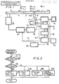
- Figure 1 is a block diagram showing an optical disc player having a control system according to an embodiment of the present invention, in association with a portion of an optical disc shown in cross section;
- Figure 2 is a flow chart to which reference will be made in explaining the operation of the optical disc player control system shown in Figure 1;
- Figure 3A is a diagrammatic representation of the data format in a video signal lead-in track area of a CDV to which the present invention may be advantageously applied;
- Figure 3B is a diagrammatic representation of the data format of one of the subcoding channels provided for each frame in Figure 3A; and
- Figures 3B1 to 3B6 are diagrammatic representations similar to that of Figure 3B, but illustrating how data identifying the TV system used in recording colour video information on the optical disc or CDV are included in the format of the subcoding channel shown in Figure 3B.
- Referring initially to Figure 1, it will be seen that an
optical disc 1 of the kind referred to as a CDV, and which is shown in cross section, is pre-recorded in radially discrete track areas A and V with audio signal data and video signal data, respectively. More specifically, theCDV 1 typically has an overall diameter of 12 cm, and is provided with a central non-recorded area E having a diameter D₁ of 4.6 cm. Arranged successively in the radially outward direction from the non-recorded central area E are an audio signal lead-in area ALI having D₁ as its inner diameter and an outer diameter D₂ of 5.0 cm, the audio signal data area A having D₂ as its inner diameter and an outer diameter D₃ of 7.4 cm, an audio signal lead-out area ALO having D₃ as its inner diameter and an outer diameter D₄ of 7.5 cm, a video signal lead-in area VLI havng D₄ as its inner diameter and an outer diameter D₅ of 7.8 cm, the video signal data area V having D₅ as its inner diameter and an outer diameter D₆ of 11.6 cm, and a video data lead-out area VLO having D₆ as its inner diameter and extending to the outer periphery of theCDV 1. - The audio signal recorded in the area A is a digital audio signal occupying a relatively low frequency band and having the format adopted as a world-wide standard for compact discs (CDs). The audio signal lead-in area ALI contains recorded data, such as data identifying the time codes and frame numbers corresponding to the several musical or other audio programmes recorded in the audio area A. Such data recorded in the audio signal lead-in area ALI is read out from the latter prior to the playback or reproducing of audio signals recorded in the area A, for use in suitably controlling the operation of an optical disc player during playback of the audio signals recorded in the area A.
- The video signal recorded in the area V according to any one of the presently employed colour TV systems, such as the PAL, NTSC or SECAM systems, is a carrier frequency modulated with luminance and colour video signals. Also recorded with the colour video signal in the area V is a digital audio signal in a frequency band below that of the frequency modulated video signal, that is, a digital audio signal similar in format to that generally recorded on CDs and hence to the digital audio signal recorded in the area A. The audio signals recorded with the video signals in the area V may be spoken words, vocalising and/or music related to the pictures or action represented by the respective video signals, while the audio signals recorded in the area A may be, for example, music programmes, unrelated to the video programmes recorded on the same CDV.
- is further shown diagrammatically in Figure 1, an optical disc player for use with the
CDV 1 comprises an optical pick-up device orhead 2 suitably positioned in opposing relation to the read-out surface of the rotatably mountedCDV 1, and being movable in the radial direction of theCDV 1 while the latter is rotated on a turntable or with a spindle by a discspindle drive motor 10. During reproducing or playback operations of the optical disc player, thehead 2 is moved in the radially outward direction, as indicated by an arrow AW, for scanning spiral tracks on the rotatedCDV 1 so as to pick up or reproduce the signals recorded on such tracks. - The signals reproduced by the optical pick-up or
head 2 are supplied through anRF amplifier 3 to a videosignal processing circuit 4 and also to an audiosignal processing circuit 6. Processed colour video information from the videosignal processing circuit 4 is supplied to a monitor orother display device 5 for normally providing a corresponding visual display when thehead 2 is scanning tracks in the area V and thereby reproducing colour video signals or information recorded thereon. In the audiosignal processing circuit 6, the signals supplied thereto from theRF amplifier 3 are error-corrected and error-concealed or compensated, and the audio signal is then converted from a digital to an analog signal which is supplied to an audio output terminal 7 to which, for example, a loudspeaker or other audio transducer may be connected. - he signal from the
RF amplifier 3 is further supplied to a clock-synchronisingsignal separator circuit 8 wherein a clock/synchronising signal is separated from the reproduced signal and is supplied to a discdrive servo circuit 9. Theservo circuit 9 provides a suitable servo control signal to the discdrive spindle motor 10 by which the rotational speed of theoptical disc 1 is determined and maintained. - Generally, an identifying signal is provided in the video signal lead-in area VLI of the
optical disc 1 and is coded, as hereinafter described in detail, to identify the TV colour system, for example, one of the PAL, NTSC or SECAM systems, in accordance with which the video signals have been recorded in the following area V. The video signal lead-in area VLI is recorded with a standard format independent of the colour TV system used for recording the video signal, for example the standardised audio CD recording format and, therefore, the output of thehead 2 when scanning the video signal lead-in area VLI is processed by the audiosignal processing circuit 6 which derives the identifying signal therefrom and supplies the same through adecoder 11 to asystem controller 12 by which necessary control functions are performed, as hereinafter described in detail. It will be appreciated that, since the identifying signal is recorded in the video signal lead-in area VLI which employs a standardised recording format independent of the TV system used for recording the video signals in the area V, the identifying signal in the video signal lead-in area VLI will always be reliably reproduced and decoded even though the TV system to which the recorded video signal corresponds may not be the same as that for which the optical disc player is intended. - Furthermore, the identifying signal is reproduced during scanning of the area VLI in advance of the area V in which the video signals are recorded. Thus, prior to the reproducing of the video signals which may have been recorded according to a TV system inconsistent with that for which the optical disc player is intended, the
decoder 11 can extract the data identifying the TV system used in recording the optical disc from the sub-code of the demodulated, error-corrected and concealed output of the audiosignal processing circuit 6. More particularly, thedecoder 11 may utilise 8-bit data, as hereinafter described, to identify the recording colour TV system of the disc, and thereby permit suitable control functions or operations to be performed prior to the actual commencement of playback or reproduction of the recorded video signals. - As shown in the flow chart of Figure 2, upon the loading of the
optical disc 1 into the optical disc player embodying this invention, thesystem controller 12 executes the following control operations. - After the optical disc has been loaded into the player, the
head 2 is made to traverse thedisc 1 in the radially outward direction indicated by the arrow AW in Figure 1 and a step [1] of Figure 2 is repeatedly executed until it is determined that the identifying (ID) signal recorded in the video signal lead-in area VLI has been read into thesystem controller 12. When the signal identifying the colour TV system used in recording the colour video signal or information in the area V on the optical disc has been read into the memory of thesystem controller 12, the program proceeds to a step [2] in which it is determined whether or not the colour TV system corresponding to the identifying signal read into the memory of thesystem controller 12 is consistent with the TV system for which the optical disc player is intended to be used. - If the TV systems are the same or consistent with each other, as represented by a YES at the decision step [2], the routine or program proceeds to a step [3] in which a flag is set to permit the playback operation of the optical disc player to proceed unimpeded and the control operations represented by the flow chart of Figure 2 are ended.
- On the other hand, if the TV system represented by the identifying signal reproduced from the video signal lead-in area VLI of the
optical disc 1 is inconsistent with an internal identifying signal provided in thesystem controller 12 for identifying the TV system for which the optical disc player is intended, that fact is represented by a NO as the answer to the decision step [2], and the routine may proceed, for example, to a step [4a] in which a disc ejection control signal is supplied from thesystem controller 12 to a disc ejection device 13 (Figure 1) by which theoptical disc 1 is ejected from the player. Further, if the identifying signal reproduced from the video signal lead-in area VLI is inconsistent with the identifying signal or data representing the TV system for which the optical disc player is intended, the routine may proceed also to a step [4b] in which a signal is generated by thesystem controller 12 for operating a visual or audible alarm or indicator 14 (Figure 1) by which the user of the optical disc player is alerted that the optical disc in use is not suited for the disc player, or at least not suited for its present operating mode. - Alternatively, when the identifying signal reproduced from the video signal lead-in area VLI of the
optical disc 1 for identifying the colour TV system according to which the colour video signal or information has been recorded on the optical disc is inconsistent with the indicating signal or data identifying the colour TV system for which the optical disc player is intended, thesystem controller 12 may respond to such inconsistency by supplying to the monitor or display means 5, a signal causing themonitor 5 to display a message alerting the user of the optical disc player to such inconsistency. Thus, for example, the displayed message may read "This Player is to be Used for NTSC Discs Only. Don't Play PAL Discs." The displayed message may be superposed on the normal video display or take the place of the latter. - Following the operation of the
disc ejection device 13 or theindicator 14, or the displaying of a message by themonitor 5, the control operations are ended. - In the above description of embodiments of this invention, it has been assumed that the CDV or other optical disc player embodying this invention has an operating mode suitable for use only in connection with optical discs having video signals recorded in accordance with only one predetermined colour TV system. However, the present invention may be embodied in a CDV player selectively capable of different modes of operation for use with CDVs having their video signals recorded in accordance with different colour TV systems, for example, the NTSC and PAL systems. In that case, if the then established mode of the optical disc player is not consistent with the colour TV system represented by the identifying signal read-in at the step [2], the
system controller 12 of the optical disc player capable of selective operation as a PAL disc player or as an NTSC disc player provides suitable control signals for changing the operating mode of the disc player, as at a step [4c] in Figure 2. Such control signals are supplied through aline 16 to the videosignal processing circuit 4, and through aline 17 to theservo circuit 9, so as to effect a change-over operation by which a suitable video signal processing circuit and a rotary disc speed characteristic of a respective operating mode are selected that are proper for the colour TV system with which the CDV or other optical disc has been recorded. - It will be appreciated that, in the optical disc player control system described above, by detecting the identifying signal recorded on the CDV for indicating the colour TV system in accordance with which the video signals are recorded, it is possible to execute the necessary control operations with substantial ease so as to ensure that, in the event of an inconsistency between the colour TV system with which the CDV is recorded and the colour TV system for which the player is intended, the cause of a defective or disturbed reproduced picture will be immediately made apparent or corrected.
- The above-mentioned colour TV system identifying signal is desirably provided at the sub-code area of the video signal lead-in area VLI of the
optical disc 1 recorded according to the CDV format. In accordance with such format, the sub-codes are symbols formed of 8 bits which are recorded for each frame (or block), as shown in Figure 3A. The sub-codes, apart from containing data for identifying the colour TV system used for the video signals recorded in the area V, contain data for performing programme functions, for example, for locating the starting points of various video programmes and the associated digital audio recorded in the area V, or for reproducing or playing back such video programmes and associated digital audio in a predetermined order. In this case, sub-coding channels P, Q, R, S, T, U, V and W are provided for 8-bit data. Bits of the sub-coding channels P and Q are utilised to perform the above-mentioned programme functions, that is, to locate the starting points of desired programmes or to achieve the playback of the programmes in a desired order. - Referring now to Figure 3B, it will be seen that a coding data series is formed by re-arranging data in the channel Q of sub-code data SUB recorded at every frame of digital audio data accompanying a video signal recorded in the video data area V (Figure 3A). A suitable coding method for the sub-code and the audio data is disclosed in detail in US Patent No. US-A-4 541 093 (issued 10 September 1985). In the coding data series shown in Figure 3B, a track number, an index number, a running time of a music programme in minutes, seconds and frames, an absolute or total running time of the music programme again given in absolute minutes, seconds and frames, and the like, are sub-coded according to the predetermined sub-coding method. It will be seen in Figure 3B that the signal format employed is similar to that referred to as "address (mode) 4" used on optical video discs and on CDVs.
- Figure 3B1 to 3B4 illustrate respective data formats of coded data recorded in the video signal lead-in area VLI and which correspond to the above-described data format shown in Figure 3B. In such a case, "00" represents the number of the track in the "Track No." area, and a Table of Contents, referred to as a "TOC", is recorded in the "Index No." area and in the area for the "absolute running time". More specifically, the "Index No." area is used as a pointer in which is provided a music or video programme number for each music and/or picture programme recorded on the CDV (Figure 3B1). Other frames are provided which have pointers A1, A2 and A0, for example, as shown in Figures 3B2, 3B3 and 3B4, respectively. By way of example, the music number of the first recorded music programme associated with a video programme is provided in the area a of the absolute running time of the frame having the frame pointer A0 (Figure 3B4). The music number of the last music programme associated with a recorded video programme is similarly provided in the area a of the absolute running time of the frame having the pointer A1 (Figure 3B2). The absolute running time up to the end of the last music programme associated with a recorded video programme is provided in the absolute running time area of the frame having the pointer A2 (Figure 3B3). Further, an identifying signal (VID) is provided in the area b, that is, the frame designation, of the absolute running time of the frame having the pointer A0 (Figure 3B4). More specifically, in the 2 digit BCD notation of 8 bits, "10" indicates the data format of a stereo audio signal recorded on a CDV having its video recorded with the NTSC colour TV system (Figure 3B5); "11" indicates the data format of a bilingual audio signal recorded on a CDV having its video signals recorded with the NTSC colour TV system; "12" indicates the data format of a stereo audio signal recorded on a video disc having its video signals recorded with the NTSC colour TV system; "13" indicates the data format of a bilingual audio signal recorded on a video disc having its video signals recorded with the NTSC colour TV system; "20" indicates the data format of a stereo audio signal recorded on a CDV having its video signals recorded with the PAL colour TV system (Figure 3B6); "21" indicates the data format of a bilingual audio signal recorded on a CDV having its video signals recorded with the PAL colour TV system; "22" indicates the data format of a stereo audio signal recorded on a video disc having its video signals recorded with the PAL colour TV system; and "23" indicates the data format of a bilingual audio signal recorded on a video disc having its video signals recorded with the PAL colour TV system.
- Thus, merely by determining whether the first digit of the 2 digit BCD notation in the area bin FIgure 3B4 is "1", as in Figure 3B5, or "2" as in FIgure 3B6, it is possible to identify whether the loaded optical disc has video signals recorded thereon in accordance with the NTSC colour TV system or the PAL colour TV system, respectively. In a similar manner, an optical disc having video signals recorded in accordance with the SECAM system may be readily identified in a similar manner.
- Alternatively, the undefined area c in each of Figures 3B1 to 3B4 between the indication of the running time of the respective music programme and the indication of the absolute running time may be used to include the data or identifying signal indicating the colour TV system used for recording the respective video signal or programme. Moreover, if desired, the TV colour system identifying signal may be provided by utilising, in the "Index No." area, a numeral larger than A3, that is, a numeral which has not yet been defined in the "Index No." area. It is also possible to provide the identifying signal for indicating the colour TV system used in recording the video signals by similarly using any available ones of the sub-code channels R to W other than the channels P and Q.
- Although the present invention is particularly advantageous when applied to a CDV player, it can be applied to any other video disc reproducing apparatus or player for reproducing video discs (such as optical video discs) having video signals recorded in a main track area of the disc and an identifying signal which may be recorded in a lead-in track area which is radially discrete from the main track area and which is scanned in advance of the latter for reproducing the identifying signal and thereby indicating the colour TV system used for recording te video signals. In such a case, since the format used for recording the lead-in track area is independent of the colour TV system employed in recording the video signals, the identifying signal in the lead-in track area is reliably detected and reproduced when scanning the lead-in track area even if the optical disc on the player has had its video signals recorded in accordance with a colour TV system that is different from the colour TV system for which the player is intended.
Claims (10)
head means (2) for initially scanning and picking up said code data recorded in said lead-in track area (VLI) and then scanning and picking up said colour video information recorded in said main track area (V);
reproducing circuit means (3 to 6) connected to said head means (2) and having at least one operating mode corresponding to a predetermined one of said TV systems for processing said colour video information from the head means (2) when said one TV system used for recorded is consistent with said predetermined one of the TV systems corresponding to said operating mode;
decoding means (11) for deriving said identifying data from the head means (2) when the latter scans said lead-in track area (VLI); and
control means (12) for controlling at least one function of said video disc player in response to a detected inconsistency between said predetermined TV system corresponding to the operating mode and said one TV system used for recording the video disc in use as determined from the derived identifying data.
Applications Claiming Priority (2)
| Application Number | Priority Date | Filing Date | Title |
|---|---|---|---|
| JP62188582A JP2638815B2 (en) | 1987-07-28 | 1987-07-28 | Disc playback device |
| JP188582/87 | 1987-07-28 |
Publications (2)
| Publication Number | Publication Date |
|---|---|
| EP0301809A1 true EP0301809A1 (en) | 1989-02-01 |
| EP0301809B1 EP0301809B1 (en) | 1992-09-09 |
Family
ID=16226197
Family Applications (1)
| Application Number | Title | Priority Date | Filing Date |
|---|---|---|---|
| EP88306875A Expired EP0301809B1 (en) | 1987-07-28 | 1988-07-26 | Video disc players |
Country Status (5)
| Country | Link |
|---|---|
| US (1) | US4914523A (en) |
| EP (1) | EP0301809B1 (en) |
| JP (1) | JP2638815B2 (en) |
| DE (1) | DE3874456T2 (en) |
| HK (1) | HK96395A (en) |
Cited By (3)
| Publication number | Priority date | Publication date | Assignee | Title |
|---|---|---|---|---|
| EP0524618A2 (en) * | 1991-07-23 | 1993-01-27 | Canon Kabushiki Kaisha | Image signal processing device |
| WO1999034601A2 (en) * | 1997-12-25 | 1999-07-08 | Kabushiki Kaisha Toshiba | System of sharing objects having a plurality of contents |
| EP1441513A2 (en) | 2003-01-24 | 2004-07-28 | Lg Electronics Inc. | Method and apparatus for setting a signal processing mode for reproduction of signals in a disc apparatus |
Families Citing this family (31)
| Publication number | Priority date | Publication date | Assignee | Title |
|---|---|---|---|---|
| JPH02198266A (en) * | 1989-01-27 | 1990-08-06 | Toshiba Corp | Image forming device |
| JP2906462B2 (en) * | 1989-07-18 | 1999-06-21 | ソニー株式会社 | Television receiver |
| JP2771266B2 (en) * | 1989-07-28 | 1998-07-02 | 株式会社日立製作所 | Multi-system video signal playback and display device |
| JP2545628B2 (en) * | 1990-02-23 | 1996-10-23 | 三菱電機株式会社 | Magnetic reproduction method |
| JP2507174B2 (en) * | 1990-11-20 | 1996-06-12 | 松下電器産業株式会社 | Optical disk drive |
| US5428456A (en) * | 1991-03-15 | 1995-06-27 | Eastman Kodak Company | Method and apparatus for adaptively reducing interline flicker of TV-displayed image |
| JP2640052B2 (en) * | 1991-06-03 | 1997-08-13 | 三洋電機株式会社 | Incorrect mounting notification system and image display system |
| JPH0594665A (en) * | 1991-09-30 | 1993-04-16 | Sony Corp | Disk player |
| JPH0612788A (en) * | 1992-06-29 | 1994-01-21 | Canon Inc | Method for recording/reproducing |
| US5432801A (en) * | 1993-07-23 | 1995-07-11 | Commodore Electronics Limited | Method and apparatus for performing multiple simultaneous error detection on data having unknown format |
| US5835669A (en) * | 1995-06-28 | 1998-11-10 | Kabushiki Kaisha Toshiba | Multilingual recording medium which comprises frequency of use data/history data and a plurality of menus which are stored in a still picture format |
| US5630006A (en) * | 1993-10-29 | 1997-05-13 | Kabushiki Kaisha Toshiba | Multi-scene recording medium and apparatus for reproducing data therefrom |
| KR100228028B1 (en) * | 1993-10-29 | 1999-11-01 | 니시무로 타이죠 | Recording medium which can cope with various languages and reproduction apparatus |
| US5764846A (en) * | 1993-10-29 | 1998-06-09 | Kabushiki Kaisha Toshiba | Multi-scene recording medium and apparatus for reproducing data therefrom |
| KR0164776B1 (en) * | 1993-10-30 | 1999-03-20 | 김광호 | Ntsc/pal signal detecting circuit of laser disc player system |
| JPH07298160A (en) * | 1994-04-25 | 1995-11-10 | Hitachi Ltd | Television receiver incorporating video cd reproducing device |
| TW250565B (en) * | 1994-10-20 | 1995-07-01 | Digital Audio Disc Corp | Mass production of multisession discs |
| US5778142A (en) * | 1994-11-24 | 1998-07-07 | Kabushiki Kaisha Toshiba | Large capacity recording medium, method and apparatus for reproducing data from a large-capacity recording medium, and method and apparatus for recording data on a large-capacity recording medium |
| CA2168327C (en) * | 1995-01-30 | 2000-04-11 | Shinichi Kikuchi | A recording medium on which a data containing navigation data is recorded, a method and apparatus for reproducing a data according to navigationdata, a method and apparatus for recording a data containing navigation data on a recording medium. |
| KR100256663B1 (en) | 1995-04-11 | 2000-05-15 | 니시무로 타이죠 | Data recording medium |
| US6009433A (en) * | 1995-04-14 | 1999-12-28 | Kabushiki Kaisha Toshiba | Information storage and information transmission media with parental control |
| US5813010A (en) * | 1995-04-14 | 1998-09-22 | Kabushiki Kaisha Toshiba | Information storage and information transmission media with parental control |
| US5838874A (en) * | 1995-05-08 | 1998-11-17 | Kabushiki Kaisha Toshiba | Audiovisual encoding system with a reduced number of audio encoders |
| US5778136A (en) * | 1995-06-15 | 1998-07-07 | Kabushiki Kaishi Toshiba | Multi-scene recording medium wherein related data segments of simultaneously proceeding scenes are recorded alternatingly and continuously thereon |
| WO1997010678A1 (en) * | 1995-09-15 | 1997-03-20 | Thomson Consumer Electronics, Inc. | Simplified input selector for video signals |
| GB9603332D0 (en) * | 1996-02-14 | 1996-04-17 | Thomson Consumer Electronics | Interface for digital recorder and display |
| US6363213B1 (en) * | 1996-02-14 | 2002-03-26 | Thomson Licensing S.A. | Interface for digital recorder and display |
| CN1112039C (en) | 1996-05-09 | 2003-06-18 | 松下电器产业株式会社 | Multimedia optical disk, reproducing device, and reproducing method capable of superposing sub-video upon main video in well-balanced state irres peative of position of main video on soreen |
| KR100417416B1 (en) * | 1997-05-29 | 2004-05-22 | 엘지전자 주식회사 | Method for performing error correction in accordance with title movement of optical disk |
| US6966023B2 (en) * | 2002-02-21 | 2005-11-15 | Mediatek Incorporation | Encoding method for an optical recorder |
| AU2003201837A1 (en) * | 2002-04-01 | 2003-10-23 | Sony Corporation | Storage medium and storage medium recording method |
Citations (6)
| Publication number | Priority date | Publication date | Assignee | Title |
|---|---|---|---|---|
| GB2002990A (en) * | 1977-06-24 | 1979-02-28 | Rca Corp | Dual standard video record player |
| EP0024858A2 (en) * | 1979-08-22 | 1981-03-11 | Discovision Associates | Video record disc and playback apparatus and method for it |
| FR2541062A1 (en) * | 1983-02-15 | 1984-08-17 | Thomson Brandt | Conversational system including a visual display device, a computer and a source of pre-recorded video-frequency information |
| GB2136654A (en) * | 1983-01-31 | 1984-09-19 | Victor Company Of Japan | Control program signal demodulating device |
| US4490810A (en) * | 1982-02-16 | 1984-12-25 | Hon David C | Automated instruction, game and data retrieval system |
| EP0223423B1 (en) * | 1985-10-21 | 1991-05-02 | Sony Corporation | Signal recording apparatus and methods |
Family Cites Families (6)
| Publication number | Priority date | Publication date | Assignee | Title |
|---|---|---|---|---|
| US4204220A (en) * | 1977-06-24 | 1980-05-20 | Rca Corporation | Dual standard video disc player |
| US4282545A (en) * | 1978-06-08 | 1981-08-04 | Blaupunkt-Werke Gmbh | Method and apparatus for playing back color video records through television receiver operating at a different color standard |
| JPS56158581A (en) * | 1980-05-10 | 1981-12-07 | Victor Co Of Japan Ltd | Recording and playback system for rotating recording medium |
| JPS5737777A (en) * | 1980-08-19 | 1982-03-02 | Victor Co Of Japan Ltd | Reproducing device for rotary information recording medium |
| US4535366A (en) * | 1982-02-22 | 1985-08-13 | Discovision Associates | Universal video data playback |
| JPH0714222B2 (en) * | 1986-04-15 | 1995-02-15 | パイオニア株式会社 | Disc recording information reproducing device |
-
1987
- 1987-07-28 JP JP62188582A patent/JP2638815B2/en not_active Expired - Lifetime
-
1988
- 1988-07-19 US US07/221,048 patent/US4914523A/en not_active Expired - Lifetime
- 1988-07-26 DE DE8888306875T patent/DE3874456T2/en not_active Expired - Lifetime
- 1988-07-26 EP EP88306875A patent/EP0301809B1/en not_active Expired
-
1995
- 1995-06-15 HK HK96395A patent/HK96395A/en not_active IP Right Cessation
Patent Citations (6)
| Publication number | Priority date | Publication date | Assignee | Title |
|---|---|---|---|---|
| GB2002990A (en) * | 1977-06-24 | 1979-02-28 | Rca Corp | Dual standard video record player |
| EP0024858A2 (en) * | 1979-08-22 | 1981-03-11 | Discovision Associates | Video record disc and playback apparatus and method for it |
| US4490810A (en) * | 1982-02-16 | 1984-12-25 | Hon David C | Automated instruction, game and data retrieval system |
| GB2136654A (en) * | 1983-01-31 | 1984-09-19 | Victor Company Of Japan | Control program signal demodulating device |
| FR2541062A1 (en) * | 1983-02-15 | 1984-08-17 | Thomson Brandt | Conversational system including a visual display device, a computer and a source of pre-recorded video-frequency information |
| EP0223423B1 (en) * | 1985-10-21 | 1991-05-02 | Sony Corporation | Signal recording apparatus and methods |
Cited By (9)
| Publication number | Priority date | Publication date | Assignee | Title |
|---|---|---|---|---|
| EP0524618A2 (en) * | 1991-07-23 | 1993-01-27 | Canon Kabushiki Kaisha | Image signal processing device |
| EP0524618B1 (en) * | 1991-07-23 | 1998-10-07 | Canon Kabushiki Kaisha | Image signal processing device |
| WO1999034601A2 (en) * | 1997-12-25 | 1999-07-08 | Kabushiki Kaisha Toshiba | System of sharing objects having a plurality of contents |
| WO1999034601A3 (en) * | 1997-12-25 | 1999-09-02 | Toshiba Kk | System of sharing objects having a plurality of contents |
| US6724979B2 (en) | 1997-12-25 | 2004-04-20 | Kabushiki Kaisha Toshiba | System of sharing objects having a plurality of contents |
| US6748160B1 (en) | 1997-12-25 | 2004-06-08 | Kabushiki Kaisha Toshiba | System of sharing objects having a plurality of contents |
| US7263271B2 (en) | 1997-12-25 | 2007-08-28 | Kabushiki Kaisha Toshiba | System of sharing objects having a plurality of contents |
| EP1441513A2 (en) | 2003-01-24 | 2004-07-28 | Lg Electronics Inc. | Method and apparatus for setting a signal processing mode for reproduction of signals in a disc apparatus |
| EP1441513A3 (en) * | 2003-01-24 | 2007-07-04 | Lg Electronics Inc. | Method and apparatus for setting a signal processing mode for reproduction of signals in a disc apparatus |
Also Published As
| Publication number | Publication date |
|---|---|
| EP0301809B1 (en) | 1992-09-09 |
| DE3874456T2 (en) | 1993-03-25 |
| JPS6432589A (en) | 1989-02-02 |
| JP2638815B2 (en) | 1997-08-06 |
| US4914523A (en) | 1990-04-03 |
| DE3874456D1 (en) | 1992-10-15 |
| HK96395A (en) | 1995-06-23 |
Similar Documents
| Publication | Publication Date | Title |
|---|---|---|
| EP0301809B1 (en) | Video disc players | |
| EP0165320B1 (en) | Disk-shaped recording medium and apparatus for reproducing the same | |
| US5530686A (en) | Record carrier having a track including audio information and additional non-audio information, and apparatus for reading and/or reproducing certain of the information included in such a track | |
| US6038366A (en) | Magnetic recording/reproducing apparatus for search programs recorded on magnetic tape | |
| JP3779127B2 (en) | Information carrier | |
| US5122886A (en) | Selective information playback from recording medium based on user input content codes | |
| EP0389689B1 (en) | Method for transmitting a transmission signal and a transmitting device and a receiving device for use in the method | |
| JP3897833B2 (en) | Information recording apparatus and information reproducing apparatus | |
| US5862107A (en) | Disc player capable of automatically interchanging a plurality of loaded discs | |
| US4970602A (en) | Disk player for displaying recorded audio signals | |
| EP0491563B1 (en) | Information recording/reproducing apparatus | |
| US6654863B2 (en) | Disc reproduction apparatus and method therefor | |
| US5410524A (en) | Recording medium apparatus for inhibiting playback of predetermined recorded portions | |
| US6970638B1 (en) | Recording medium reproducing apparatus | |
| US5703994A (en) | Index processor for digital VCR and method therefor | |
| EP1679707B1 (en) | Method of reproducing documents comprising impaired sequences and, associated reproduction device | |
| JP2696843B2 (en) | Playback method | |
| EP0206569A2 (en) | Display apparatus for multi-channel PCM recorder | |
| JP3067664B2 (en) | Disc playback device | |
| JP2600585B2 (en) | Disk recording medium | |
| JP3090895B2 (en) | Recording medium playback device | |
| EP0436441B1 (en) | Data reproducing apparatus | |
| KR970011829B1 (en) | Automatic viss inserting apparatus in a complex product of optical disk player and video cassette recorder | |
| JPH0322279A (en) | Information signal recording medium and player for the same | |
| KR100203859B1 (en) | Control signal detecting method of video compact disc |
Legal Events
| Date | Code | Title | Description |
|---|---|---|---|
| PUAI | Public reference made under article 153(3) epc to a published international application that has entered the european phase |
Free format text: ORIGINAL CODE: 0009012 |
|
| 17P | Request for examination filed |
Effective date: 19880812 |
|
| AK | Designated contracting states |
Kind code of ref document: A1 Designated state(s): DE GB NL |
|
| 17Q | First examination report despatched |
Effective date: 19911204 |
|
| GRAA | (expected) grant |
Free format text: ORIGINAL CODE: 0009210 |
|
| AK | Designated contracting states |
Kind code of ref document: B1 Designated state(s): DE GB NL |
|
| REF | Corresponds to: |
Ref document number: 3874456 Country of ref document: DE Date of ref document: 19921015 |
|
| PLBE | No opposition filed within time limit |
Free format text: ORIGINAL CODE: 0009261 |
|
| STAA | Information on the status of an ep patent application or granted ep patent |
Free format text: STATUS: NO OPPOSITION FILED WITHIN TIME LIMIT |
|
| 26N | No opposition filed | ||
| REG | Reference to a national code |
Ref country code: GB Ref legal event code: IF02 |
|
| PGFP | Annual fee paid to national office [announced via postgrant information from national office to epo] |
Ref country code: DE Payment date: 20070719 Year of fee payment: 20 |
|
| PGFP | Annual fee paid to national office [announced via postgrant information from national office to epo] |
Ref country code: GB Payment date: 20070725 Year of fee payment: 20 |
|
| PGFP | Annual fee paid to national office [announced via postgrant information from national office to epo] |
Ref country code: NL Payment date: 20070624 Year of fee payment: 20 |
|
| REG | Reference to a national code |
Ref country code: GB Ref legal event code: PE20 Expiry date: 20080725 |
|
| NLV7 | Nl: ceased due to reaching the maximum lifetime of a patent |
Effective date: 20080726 |
|
| PG25 | Lapsed in a contracting state [announced via postgrant information from national office to epo] |
Ref country code: NL Free format text: LAPSE BECAUSE OF EXPIRATION OF PROTECTION Effective date: 20080726 |
|
| PG25 | Lapsed in a contracting state [announced via postgrant information from national office to epo] |
Ref country code: GB Free format text: LAPSE BECAUSE OF EXPIRATION OF PROTECTION Effective date: 20080725 |