EP0286419A2 - Method and apparatus for analysing liquid properties - Google Patents
Method and apparatus for analysing liquid properties Download PDFInfo
- Publication number
- EP0286419A2 EP0286419A2 EP88303147A EP88303147A EP0286419A2 EP 0286419 A2 EP0286419 A2 EP 0286419A2 EP 88303147 A EP88303147 A EP 88303147A EP 88303147 A EP88303147 A EP 88303147A EP 0286419 A2 EP0286419 A2 EP 0286419A2
- Authority
- EP
- European Patent Office
- Prior art keywords
- guide
- radiation
- drop
- liquid
- providing
- Prior art date
- Legal status (The legal status is an assumption and is not a legal conclusion. Google has not performed a legal analysis and makes no representation as to the accuracy of the status listed.)
- Granted
Links
Images


Classifications
-
- B—PERFORMING OPERATIONS; TRANSPORTING
- B01—PHYSICAL OR CHEMICAL PROCESSES OR APPARATUS IN GENERAL
- B01L—CHEMICAL OR PHYSICAL LABORATORY APPARATUS FOR GENERAL USE
- B01L3/00—Containers or dishes for laboratory use, e.g. laboratory glassware; Droppers
- B01L3/02—Burettes; Pipettes
- B01L3/0241—Drop counters; Drop formers
-
- G—PHYSICS
- G01—MEASURING; TESTING
- G01N—INVESTIGATING OR ANALYSING MATERIALS BY DETERMINING THEIR CHEMICAL OR PHYSICAL PROPERTIES
- G01N21/00—Investigating or analysing materials by the use of optical means, i.e. using sub-millimetre waves, infrared, visible or ultraviolet light
- G01N21/17—Systems in which incident light is modified in accordance with the properties of the material investigated
- G01N21/25—Colour; Spectral properties, i.e. comparison of effect of material on the light at two or more different wavelengths or wavelength bands
- G01N21/255—Details, e.g. use of specially adapted sources, lighting or optical systems
-
- G—PHYSICS
- G01—MEASURING; TESTING
- G01N—INVESTIGATING OR ANALYSING MATERIALS BY DETERMINING THEIR CHEMICAL OR PHYSICAL PROPERTIES
- G01N11/00—Investigating flow properties of materials, e.g. viscosity, plasticity; Analysing materials by determining flow properties
- G01N11/02—Investigating flow properties of materials, e.g. viscosity, plasticity; Analysing materials by determining flow properties by measuring flow of the material
-
- G—PHYSICS
- G01—MEASURING; TESTING
- G01N—INVESTIGATING OR ANALYSING MATERIALS BY DETERMINING THEIR CHEMICAL OR PHYSICAL PROPERTIES
- G01N13/00—Investigating surface or boundary effects, e.g. wetting power; Investigating diffusion effects; Analysing materials by determining surface, boundary, or diffusion effects
- G01N13/02—Investigating surface tension of liquids
- G01N2013/0241—Investigating surface tension of liquids bubble, pendant drop, sessile drop methods
-
- G—PHYSICS
- G01—MEASURING; TESTING
- G01N—INVESTIGATING OR ANALYSING MATERIALS BY DETERMINING THEIR CHEMICAL OR PHYSICAL PROPERTIES
- G01N21/00—Investigating or analysing materials by the use of optical means, i.e. using sub-millimetre waves, infrared, visible or ultraviolet light
- G01N21/01—Arrangements or apparatus for facilitating the optical investigation
- G01N21/03—Cuvette constructions
- G01N2021/0346—Capillary cells; Microcells
- G01N2021/035—Supports for sample drops
-
- G—PHYSICS
- G01—MEASURING; TESTING
- G01N—INVESTIGATING OR ANALYSING MATERIALS BY DETERMINING THEIR CHEMICAL OR PHYSICAL PROPERTIES
- G01N21/00—Investigating or analysing materials by the use of optical means, i.e. using sub-millimetre waves, infrared, visible or ultraviolet light
- G01N21/17—Systems in which incident light is modified in accordance with the properties of the material investigated
- G01N2021/1738—Optionally different kinds of measurements; Method being valid for different kinds of measurement
- G01N2021/174—Optionally different kinds of measurements; Method being valid for different kinds of measurement either absorption-reflection or emission-fluorescence
-
- G—PHYSICS
- G01—MEASURING; TESTING
- G01N—INVESTIGATING OR ANALYSING MATERIALS BY DETERMINING THEIR CHEMICAL OR PHYSICAL PROPERTIES
- G01N21/00—Investigating or analysing materials by the use of optical means, i.e. using sub-millimetre waves, infrared, visible or ultraviolet light
- G01N21/84—Systems specially adapted for particular applications
- G01N21/85—Investigating moving fluids or granular solids
- G01N2021/8557—Special shaping of flow, e.g. using a by-pass line, jet flow, curtain flow
- G01N2021/8564—Sample as drops
-
- G—PHYSICS
- G01—MEASURING; TESTING
- G01N—INVESTIGATING OR ANALYSING MATERIALS BY DETERMINING THEIR CHEMICAL OR PHYSICAL PROPERTIES
- G01N35/00—Automatic analysis not limited to methods or materials provided for in any single one of groups G01N1/00 - G01N33/00; Handling materials therefor
- G01N35/10—Devices for transferring samples or any liquids to, in, or from, the analysis apparatus, e.g. suction devices, injection devices
- G01N2035/1027—General features of the devices
- G01N2035/1034—Transferring microquantities of liquid
- G01N2035/1046—Levitated, suspended drops
-
- G—PHYSICS
- G01—MEASURING; TESTING
- G01N—INVESTIGATING OR ANALYSING MATERIALS BY DETERMINING THEIR CHEMICAL OR PHYSICAL PROPERTIES
- G01N21/00—Investigating or analysing materials by the use of optical means, i.e. using sub-millimetre waves, infrared, visible or ultraviolet light
- G01N21/17—Systems in which incident light is modified in accordance with the properties of the material investigated
- G01N21/1702—Systems in which incident light is modified in accordance with the properties of the material investigated with opto-acoustic detection, e.g. for gases or analysing solids
-
- G—PHYSICS
- G01—MEASURING; TESTING
- G01N—INVESTIGATING OR ANALYSING MATERIALS BY DETERMINING THEIR CHEMICAL OR PHYSICAL PROPERTIES
- G01N21/00—Investigating or analysing materials by the use of optical means, i.e. using sub-millimetre waves, infrared, visible or ultraviolet light
- G01N21/17—Systems in which incident light is modified in accordance with the properties of the material investigated
- G01N21/41—Refractivity; Phase-affecting properties, e.g. optical path length
- G01N21/43—Refractivity; Phase-affecting properties, e.g. optical path length by measuring critical angle
- G01N21/431—Dip refractometers, e.g. using optical fibres
-
- G—PHYSICS
- G01—MEASURING; TESTING
- G01N—INVESTIGATING OR ANALYSING MATERIALS BY DETERMINING THEIR CHEMICAL OR PHYSICAL PROPERTIES
- G01N2201/00—Features of devices classified in G01N21/00
- G01N2201/08—Optical fibres; light guides
Landscapes
- Chemical & Material Sciences (AREA)
- Physics & Mathematics (AREA)
- Health & Medical Sciences (AREA)
- General Physics & Mathematics (AREA)
- Pathology (AREA)
- Analytical Chemistry (AREA)
- Biochemistry (AREA)
- General Health & Medical Sciences (AREA)
- Spectroscopy & Molecular Physics (AREA)
- Immunology (AREA)
- Life Sciences & Earth Sciences (AREA)
- Clinical Laboratory Science (AREA)
- Chemical Kinetics & Catalysis (AREA)
- Investigating Or Analysing Materials By Optical Means (AREA)
- Sampling And Sample Adjustment (AREA)
- Investigating Or Analysing Materials By The Use Of Chemical Reactions (AREA)
- Optical Measuring Cells (AREA)
Abstract
Description
- The invention relates to an apparatus and method for measuring a property of a liquid.
- According to the invention there is provided an apparatus for measuring a property of a liquid, comprising at least one guide for electromagnetic radiation, means for directing electromagnetic radiation into the guide, means for providing at least one drop of liquid in contact with the guide at a position where radiation from the guide can enter the drop, and means for deriving a signal which is a function of the interaction of the radiation with the liquid of the drop.
- The liquid may be formed as a static drop suspended at the free end of the radiation guide, e.g. a light guide, or it may be a dynamic drop - one of a succession of drops allowed to drip from the end of the guide. Thus one can perform measurements on small volumes, or continuously monitor a liquid in a flow process by bleeding off sample droplets for measurement.
- The electromagnet radiation may be any such radiation which can be guided alone a radiation guide to the drop, and may be continuous, pulsed or otherwise modulated to facilitate the particular analysis being performed.
- The electromagnetic radiation supplied to the drop along the guide may be combined with other electromagnetic energy or other forms of energy (for example acoustic energy) also supplied to the drop, either applied along the guide, by an external field or by any other method of energising the drop. Such other forms of energy may be used to pump a process in or outside the drop in order to change the conditions relating to the measurement being performed.
- The temperature or other ambient conditions may be changed in any desired manner to vary the physical conditions for the measurement or as experimental control variables.
- The signal which is a function of the interaction of the liquid with the radiation may be derived by any device appropriate to the particular analysis, and may comprise a dedicated instrument or system or an instrument or system with general applications.
- Most simply, the signal is derived by measuring the level of radiation reflected internally of the drop into the same or a further radiation guide. However, other forms of sensor or probe may be used.
- The invention further provides a method for measuring a property of a liquid, comprising providing at least one guide for electromagnetic radiation, directing electromagnetic radiation into the guide, providing at least one drop of liquid in contact with the guide at a position where radiation from the guide can enter the drop, and deriving a signal which is a function of the interaction of the radiation with the liquid of the drop.
- Although the invention is described herein using optical fibres as radiation guides, the latter could be formed by other radiation-guiding means such as capilliary tubes or other radiation guides.
- Furthermore, while the invention is described herein in terms of supplying the drop to the radiation guide by gravity feed, other techniques are possible. For example, drop could be formed and suspended in an electric field, and brought to the measuring position from below, or from the side. This would also permit making some measurements while the drop is approaching the guide.
- Also, the drop need not be attached to the end of the guide, as described herein. It can be attached to any part of the guide where the radiation is capable of passing into it, for example, at an intermediate position on the guide where the radiation is coupled into the drop via the evanescent wave.
- The invention can be used inter alia to measure a wide range of physical, chemical, electrical, opto-acoustical and other properties of the liquid, either singly or in any combination. These include:
- 1. Refractive index.
- 2. Surface tension.
- 3. Specific gravity
- 4. Viscosity (absolute or kinematic).
- 5. Turbidity.
- 6. Absorption or chemical composition.
- 7. Fluorescence.
- 8. pH.
- 9. Conductivity or ion type.
- 10. Opto-acoustical properties.
- 11. Adhesion or other mechanical properties.
- 12. Pressure head.
- 13. Liquid volume.
- 14. Any other properties, such as humidity, which may condition the drop and so be indirectly measured.
- Embodiments of the invention will now be described, by way of example, with reference to the accompanying drawings in which:
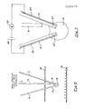
- Figure 1 is a schematic diagram of an embodiment of an apparatus for performing the invention;
- Figure 2 is an enlarged view of the downwardly facing free ends of the optical fibres shown in Figure 1;
- Figure 3 illustrates how the fibres may be securely supported in the position shown in Figure 2 for handling and protection;
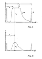
- Figure 4 is a voltage/time diagram of a typical signal produced by the detector circuit of Figure 1 for a transparent liquid with low absorption;
- Figure 5 is a similar voltage/time diagram for a liquid having significant absorption;
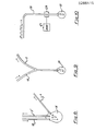
- Figure 6 shows a form of the apparatus for measuring pH;
- Figure 7 shows a form of the apparatus for measuring conductivity; and
- Figures 8 to 10 illustrate alternative light guide and detection arrangements.
- Referring to Figure 1, first and second radiation guides in the form of
optical fibres 10 and 11 are brought close together at their downwardly facingfree ends liquid feed pipe 14 is also brought into close proximity to theends drop 15, or a succession of drops, at the ends of the fibres. - The
pipe 14 may be supplied by a syringe type plunger so that a singlestatic drop 15 may be formed, or alternatively thepipe 14 may be fed by a constant head of liquid from a constant head apparatus so that a succession ofreproducible drops 15 are fed under gravity to theends - Referring to Figure 2, which shows the free ends of the
fibres 10 and 11 and thepipe 14 to an enlarged scale, at theirfree ends fibres 10 and 11 are disposed symmetrically on either side of a vertical plane 17 at an angle of 18° to 22° with respect to one another, and preferably at an angle of 20° as shown. - The fibres may be polymethyl methacrylate fibres with an actual fibre core diameter (i.e. excluding the outer casing) of 1mm. The centres of their lower ends are spaced apart by about 2.6 mm as shown. The fibres may be step index fibres. Graded index or monomode fibres may be used although it will be readily understood that in such cases other geometries must be used for optimum working. It will be noted that the
pipe 14 is offset from the centre plane 17 between thefibres 10 and 11, so that the liquid flows down the fibre 11 to theends - In order to securely support the
fibres 10 and 11 and thepipe 14 in their relative positions shown in Figure 2, their lower free ends are fixed in epoxy resin 18 in a glass cylinder 19, Figure 3, the lower end of the cylinder extending slightly below the free ends 12 and 13 of the fibres for protection and handling. - Referring again to Figure 1, infra-red (IR) or visible radiation in the range 0.3um to 1.3um is supplied by an LED, solid state laser or other radiation source 20 which directs radiation into the end of the
optical fibre 10 remote from thedrop 15, and such radiation travels along thefibre 10 to thedrop 15. - The radiation may be continuous, varied in a cyclic manner, or otherwise varied to facilitate a particular measurement. In the present case the radiation source 20 is a "Honeywell Sweet Spot" pulsed LED operated in the range 50Hz to 10KHz by a square
wave signal generator 21. Thegenerator 21 provides for stable operation of the LED 20, as well as providing advantages in measurement to be described. - Radation from the source 20 travels along the
fibre 10 to reach thedrop 15 and is reflected internally of thedrop 15 to travel up to the second optical fibre 11 to a detector circuit 22 (e.g. an IR detector or light-dependent resistor) where the level of the reflected radiation is measured. For example, thedetector 22 may be an infra-red phototransistor configured in a simple potential divider circuit with approximately 9 volts supply. The detected output level is supplied to one or more of adigital voltmeter 23, astorage oscilloscope 24, achart recorder 25 and adata logging computer 26 with associatedprinter 27. - In the case of a liquid drop held suspended at the
ends digital voltmeter 23, is directly proportional so the refractive index of the liquid, assuming constant drop size and absorbance. - It was found in the static mode by experiment that the most reproducible results were obtained by careful tilting of the apparatus out of the vertical plane (i.e. out of the plane of Figure 2) and adjusting the drop size, using the syringe, to obtain a maximum signal. It will be noted that the modulation of the IR source 20 by the
generator 21 is not registered by thedigital voltmeter 23. - Thus, by taking voltmeter reading for liquids of known refractive index and plotting these as a straight line graph of refractive index against the voltmeter reading, the refractive index of any other liquid can be determined from the graph by its voltmeter reading.
- Other properties of the liquid can also be determined by the static method, for example, absorbance (concentration of dissolved chemicals in a given solvent).
- Conventionally, absorbance is measured using a cuvette. Light is passed through the cuvette, and the absorbance A is given by A = log(Io/I) where Io is the incident intensity and is the intensity after passing through the cuvette. Since A = E.c.1 where E = extinction coefficient, c = concentration and 1 = distance travelled by the light through the cuvette, c (concentration) can be determined from A, since E can be obtained from reference books and 1 is known for the cuvette.
- However, cuvettes are subject to variations in tolerance, and since a
drop 15 can be reproduced almost exactly on the present apparatus, it can therefore effectively constitute an almost ideal cuvette. Thus by plotting A against c for liquids of known concentration, where in this case Io = input level to the drop and I = output level as measured by thedigital voltmeter 23, a calibration curve can be obtained. - In the case of dynamic drops, Figure 4 shows (for a relatively transparent liquid with low absorption) the voltage/time diagram as each drop falls from the ends of the
optical fibres 10 and 11 into a beaker 28. This diagram will be produced by theoscilloscope 24, thechart recorder 25, and theprinter 27 of thecomputer 26. The broad peak 30 corresponds to the growth of the drop, and the finalnarrow peak 31 is from the ends of the optical fibres. - It is to be understood that the diagram used in the present analysis is one where the height of the
narrow peak 31 is as close to the height of the broad peak 30 as possible, and this is achieved by tilting the apparatus as previously described until the best results are achieved. - From such a diagram, the time period T₂ can be used to determine the refractive index of the liquid using a calibration procedure. Thus, if n (refractive index) is plotted against T₂/V (where V - volume per second) for a number of liquids of known refractive index a calibration curve is obtained which can be used to determine the refractive index of liquids whose refractive index is not known.
- Further, the overall cycle period T₁ of the diagram is a function of the surface tension of the liquid and the kinematic viscosity in a gravity feed constant head apparatus. The kinematic viscosity can be determined by a calibration technique from the
slope 32, and the surface tension can then be determined from the kinematic viscosity and T₁. - The width of the peak 31 at half its amplitude is a measure of the specific gravity of the liquid.
- Other properties can be determined by processing the data from the trace, either manually from the trace or by suitably programming the
computer 26. In this connection, the square wave superimposed on the trace assists in ascertaining the various measuring points required. Differentiation and double differentiation will also help to identify points of interest, and if necessary, any modulation applied by the generator 21 (Figure 1) can be filtered out before this is done. - Figure 5 shows how the trace of Figure 4 is modified by absorption. For chemical analysis, an analysis time TA is fixed and the height of the signal S₁ for an absorbing liquid can be measured for different concentrations at one measurement wavelength. A graph of absorbance A = log(So/S₁) can be plotted against concentration and from this calibration graph the concentration of an unknown solution can be determined.
- Alternatively, chemical analysis may be performed by integrating the detected signal, i.e. measuring the area under the trace during the cycle period T₁. The area will decrease with increasing concentration.
- The analysis of turbidity can be done in a similar fashion by measuring the decrease in So with increasingly turbid solutions.
- If the liquid is flourescent, then an excitation wavelength, such as UV or blue, can be used and the signal measured at the
detector 22 which in this case has a monochromatic filter at a longer wavelength, such as orange, placed in front of it. The measurement would be done by the standard fluorescent methods of plotting this signal against the concentration of the fluorescent substance to obtain a calibration graph from which an unknown can be determined. - Referring now to Figure 6, the appartus is shown modified to measure pH. In this case, a pair of large
area capacitor plates - Each
drop 15 becomes charged as it detaches from the ends of the fibres, usually positively under normal atmospheric conditions, which charges up thelower plate 41 of the capacitor. Thus the drops are increasingly repelled, so that T₁ increases until a maximum is reached where the additional charge from each drop equals the leakage from theplate 41. This maximum value of T₁ gives a measure of the pH value of the liquid. - An AC or DC voltage supply can be connected across the plates of the capacitor to vary T₁, and these variations can be related to the electrical properties of the liquid. Likewise, the liquid feed could be charged to vary T₁.
- The pH of the solution can be obtained by placing the drop in an electric field and the drop time, T₁, can be made to vary according to the voltage developed on the capacitor.
- A voltage will appear by self charging of the capacitor due to the rupture of the drop from the body of supporting liquid, and this will lead to an increase in the drop time, which itself will be a function of the electrical properties of the liquid. The electrical condition of the atmosphere can be monitored via the simple fibre drop analyser by connecting the liquid drop feed to a voltmeter and allowing the induced charge on the drop to continue to carry away charge until the equilibrium situation is obtained when the voltage of the feed equates with the voltage of the potential of the surrounding air.
- Referring to Figure 7, the conductivity of a liquid can be measured by providing
respective electrodes fibre 10 and 11 respectively.Respective conductors electrodes constant voltage supply 46 and anammeter 47. - An alternative bubble analysis can be devised to work on the principle above, with downward facing and inwardly pointing fibres directed at a liquid surface to carry out the analysis on an exploding bubble released from the bottom of a container.
- The foregoing describes just some of the many uses of the apparatus described.
- For example, the apparatus can be used as a rain guage. If the syringe or constant head apparatus 16 is replaced by, for example, a funnel open at the top to rainfall and whose bottom is connected to the
pipe 14, the rainfall may be measured by counting the total number and/or frequency of drops. This measurement may be effected, for example, by counting the broad peaks 30 of the trace in thecomputer 26 or in a separate counter. - Also, the time T₁ could be used to monitor pressure head where this was important for control purposes.
- The dynamic properties of a liquid may be examined with the drop in situ. Thus the drop can be caused to oscillate, while remaining on the ends of the fibres, by the application of varying electromagnetic or electrostatic fields, or by mechanical vibration. In this case the trace would have symmetrical peaks 30, and no
peaks 31. The period, amplitude and phase of the oscillations, as measured by thedetector 22, would give information regarding the mechanical and/or electrical properties of the liquid depending on the circumstances of the procedure. - While the above has shown an arrangement where there are two optical fibres, a source fibre and a receiving fibre, other geometries for the fibre optics or other light guides are possible.
- Thus, as shown in Figure 8, the
source fibre 10 injects light into a drop which couples into two receiving optical fibres 11ʹ and 11ʺ which can detect individually the quantity of radiation coupled to a respective detector at the end of the fibre, or it may be used to compare the difference between the light coupled to produce a differential analyser. - In Figure 9, a single bifurcated optical fibre is used, the
left hand branch 10 constituting the source, and the right hand branch 11 the receiver. This design produces an increased coupling to the receiving fibre when the fibre is tilted, but one which is asymmetric having a preferential clockwise tilt. A multi-fibre system could also be used to carry many wavelengths into the drop to enable, for example, the chemical analysis of several components simultaneously. - Finally, in Figure 10, a
single fibre 10 may be used, and detection is accomplished by a sensitive opto-acoustical microphone 50 andamplifier 51 which detects the sound produced in the sample by the pulsed source (17, 18 in Figure 1). In this case the sample liquid may be opaque and does not need to transmit radiation. - The commercial applications of the apparatus are many:
- 1. A system monitor and controller for an industrial flow process.
- 2. A water monitor for monitoring a selection of quantities for a reservoir or industrial process.
- 3. A household water quantity and quality meter.
- 4. A rain guage to measure the properties of rain water, e.g. acid rain.
- 5. A laboratory liquid analyser, either dedicated for a specific application or general purpose.
- 6. A medical or clinical drip analyser.
- 7. A saccharimeter.
- Naturally the use of an opto-acoustical microphone is not limited to the embodiment of Figure 10 but could be used more generally, for example, in relation to the receiving fibre 11 in Figure 1.
Claims (17)
Priority Applications (1)
| Application Number | Priority Date | Filing Date | Title |
|---|---|---|---|
| AT88303147T ATE77881T1 (en) | 1987-04-10 | 1988-04-08 | METHOD AND DEVICE FOR MEASURING THE PROPERTIES OF A LIQUID. |
Applications Claiming Priority (2)
| Application Number | Priority Date | Filing Date | Title |
|---|---|---|---|
| IE94787 | 1987-04-10 | ||
| IE94787 | 1987-04-10 |
Publications (3)
| Publication Number | Publication Date |
|---|---|
| EP0286419A2 true EP0286419A2 (en) | 1988-10-12 |
| EP0286419A3 EP0286419A3 (en) | 1989-08-09 |
| EP0286419B1 EP0286419B1 (en) | 1992-07-01 |
Family
ID=11020118
Family Applications (1)
| Application Number | Title | Priority Date | Filing Date |
|---|---|---|---|
| EP88303147A Expired - Lifetime EP0286419B1 (en) | 1987-04-10 | 1988-04-08 | Method and apparatus for analysing liquid properties |
Country Status (7)
| Country | Link |
|---|---|
| US (1) | US4910402A (en) |
| EP (1) | EP0286419B1 (en) |
| JP (1) | JPS6438633A (en) |
| AT (1) | ATE77881T1 (en) |
| AU (1) | AU625333B2 (en) |
| DE (1) | DE3872427T2 (en) |
| ZA (1) | ZA882454B (en) |
Cited By (15)
| Publication number | Priority date | Publication date | Assignee | Title |
|---|---|---|---|---|
| GB2218511A (en) * | 1988-05-09 | 1989-11-15 | Zeiss Jena Veb Carl | Apparatus for the automatic photometric analysis of small specimens |
| EP0364203A1 (en) * | 1988-10-10 | 1990-04-18 | Phyber Holdings Limited | A liquid drop forming device |
| EP0478410A1 (en) * | 1990-09-24 | 1992-04-01 | THE DOW CHEMICAL COMPANY (a Delaware corporation) | Probe for photoacoustic analysis |
| GB2283567A (en) * | 1993-10-29 | 1995-05-10 | Univ Brunel | Fibre optic sensor device |
| US5610400A (en) * | 1994-03-02 | 1997-03-11 | Instrumentarium Oy | Spectroscopic measuring sensor for the analysis of mediums |
| WO1997034175A1 (en) * | 1996-03-13 | 1997-09-18 | Visionex, Inc. | Method and apparatus for improved fiber optic light management |
| WO1998009151A1 (en) * | 1996-08-31 | 1998-03-05 | Herbert Windolph | Process and device for determining the volume of liquid droplets |
| US5878178A (en) * | 1995-11-20 | 1999-03-02 | Visionex Inc | Optical fiber with enhanced light collection and illumination and having highly controlled emission and acceptance patterns |
| WO1999011373A2 (en) * | 1997-08-28 | 1999-03-11 | Hunter Ian W | Apparatus and methods for droplet microchemistry |
| US5901261A (en) * | 1997-06-19 | 1999-05-04 | Visionex, Inc. | Fiber optic interface for optical probes with enhanced photonic efficiency, light manipulation, and stray light rejection |
| US5911017A (en) * | 1996-07-31 | 1999-06-08 | Visionex, Inc. | Fiber optic interface for laser spectroscopic Raman probes |
| US5953477A (en) * | 1995-11-20 | 1999-09-14 | Visionex, Inc. | Method and apparatus for improved fiber optic light management |
| US6174424B1 (en) | 1995-11-20 | 2001-01-16 | Cirrex Corp. | Couplers for optical fibers |
| US6404953B1 (en) | 1996-03-13 | 2002-06-11 | Cirrex Corp. | Optical assembly with high performance filter |
| US6580935B1 (en) | 1999-03-12 | 2003-06-17 | Cirrex Corp. | Method and system for stabilizing reflected light |
Families Citing this family (24)
| Publication number | Priority date | Publication date | Assignee | Title |
|---|---|---|---|---|
| CA2001758A1 (en) * | 1988-10-31 | 1990-04-30 | Wilfried Schoeps | Apparatus for the simultaneous non-contacting testing of a plurality of points on a test material, as well as the use thereof |
| US5343045A (en) * | 1993-06-11 | 1994-08-30 | Ontario Hydro | Method and device for measuring moisture content |
| US5766959A (en) * | 1996-05-24 | 1998-06-16 | The Dow Chemical Company | Method for determining a component using a liquid film or droplet |
| JPH11291895A (en) * | 1998-04-09 | 1999-10-26 | Honda Motor Co Ltd | System for administrating brake fluid boiling point |
| GB9908170D0 (en) * | 1999-04-09 | 1999-06-02 | Central Research Lab Ltd | System and method for analysing a material |
| EP1950553B1 (en) | 1999-08-20 | 2016-02-24 | Nanodrop Technologies LLC | Liquid photometer using surface tension to contain sample |
| WO2001014855A1 (en) | 1999-08-20 | 2001-03-01 | Charles William Robertson | Liquid photometer using surface tension to contain sample |
| GB0012184D0 (en) * | 2000-05-22 | 2000-07-12 | Ibm | Suface analysis |
| US6809826B2 (en) * | 2001-02-20 | 2004-10-26 | Charles William Robertson | Liquid photometer using surface tension to contain sample |
| US7758744B2 (en) * | 2001-10-05 | 2010-07-20 | Stephen Eliot Zweig | Dual glucose-turbidimetric analytical sensors |
| US7224448B2 (en) * | 2004-11-16 | 2007-05-29 | Agilent Technologies, Inc. | Apparatus and methods for evaluating an optical property of a liquid sample |
| JP4773464B2 (en) * | 2005-02-18 | 2011-09-14 | ノーマン・マクミラン | Tensio Graphic Drophead |
| US7277167B2 (en) * | 2005-09-13 | 2007-10-02 | Agilent Technologies, Inc. | Modular cuvettes and methods for use thereof |
| US20070081159A1 (en) * | 2005-10-11 | 2007-04-12 | Giffin Kristin M | Apparatus and methods for evaluating an optical property of a liquid sample |
| GB0523231D0 (en) * | 2005-11-15 | 2005-12-21 | Redfern Jonathan | Liquid photometer using disposable pipette tip vessel |
| EP2027452B1 (en) * | 2006-05-12 | 2017-06-28 | Carl Stuart Limited | Microvolume analysis system |
| EP1950550A1 (en) * | 2007-01-25 | 2008-07-30 | Flamac | Method and apparatus for measuring viscosity and surface tension |
| US7808641B2 (en) * | 2007-04-13 | 2010-10-05 | C Technologies Inc. | Interactive variable pathlength device |
| WO2010033427A1 (en) * | 2008-09-19 | 2010-03-25 | Brooks Automation, Inc. | Ionization gauge with emission current and bias potential control |
| WO2013131017A1 (en) | 2012-03-02 | 2013-09-06 | Laxco, Inc. | Multichannel analytical instruments for use with specimen holders |
| US8912007B2 (en) | 2013-01-22 | 2014-12-16 | Tecan Trading Ag | Optical measuring apparatus and method for the analysis of samples contained in liquid drops |
| US9488576B2 (en) | 2013-01-22 | 2016-11-08 | Tecan Trading Ag | Optical measuring apparatus and method for the analysis of samples contained in liquid drops |
| US9488579B2 (en) | 2013-01-22 | 2016-11-08 | Tecan Trading Ag | Optical measuring apparatus and method for the analysis of samples contained in liquid drops |
| US11054364B2 (en) | 2018-12-17 | 2021-07-06 | Thermo Finnigan Llc | Apparatus and methods for handling and spectrophotometry of small liquid samples |
Citations (4)
| Publication number | Priority date | Publication date | Assignee | Title |
|---|---|---|---|---|
| GB2092758A (en) * | 1981-02-06 | 1982-08-18 | Nat Iranian Oil Co | Process and Apparatus for Determining the Characteristics of a Drop of a Liquid Required for Calculating the Surface Tension of the Liquid |
| GB2105034A (en) * | 1981-09-04 | 1983-03-16 | Westinghouse Electric Corp | Fiber optic impurity detector |
| EP0144928A2 (en) * | 1983-12-08 | 1985-06-19 | Hoechst Aktiengesellschaft | Photometric head for small sample volumes |
| US4646562A (en) * | 1984-10-30 | 1987-03-03 | Miller Brewing Company | Method and apparatus for detecting relative dynamic liquid surface activity |
Family Cites Families (10)
| Publication number | Priority date | Publication date | Assignee | Title |
|---|---|---|---|---|
| BE790280A (en) * | 1971-11-19 | 1973-04-19 | Technicon Instr | PHOTOMETRIC ANALYSIS OF A GOUTELLET OF A LIQUID SAMPLE |
| US4006360A (en) * | 1974-08-21 | 1977-02-01 | Block Engineering, Inc. | Method of discriminating between dyed particles and background fluorescence of the dye |
| GB1533242A (en) * | 1975-01-21 | 1978-11-22 | Perkin Elmer Ltd | Utilizing radiation-derived electrical signals |
| JPS5376879A (en) * | 1976-12-18 | 1978-07-07 | Haruaki Tamaoki | Device for measuring dewdrop* cloud* and dirt on glass surface |
| JPS567037A (en) * | 1979-06-29 | 1981-01-24 | Fumio Inaba | Remote substance density analyzing optical measuring apparatus |
| US4303343A (en) * | 1980-02-29 | 1981-12-01 | Bell Telephone Laboratories, Incorporated | Optoacoustic spectroscopy of condensed matter in bulk form |
| JPS5973753A (en) * | 1982-10-21 | 1984-04-26 | Toshiba Corp | Ultra-minute amount spectrophotometer |
| JPS59155574U (en) * | 1983-04-04 | 1984-10-18 | オ−バル機器工業株式会社 | droplet detector |
| JPS60577U (en) * | 1983-06-15 | 1985-01-05 | オムロン株式会社 | water drop sensor |
| US4660971A (en) * | 1984-05-03 | 1987-04-28 | Becton, Dickinson And Company | Optical features of flow cytometry apparatus |
-
1988
- 1988-03-31 US US07/175,859 patent/US4910402A/en not_active Expired - Lifetime
- 1988-04-08 EP EP88303147A patent/EP0286419B1/en not_active Expired - Lifetime
- 1988-04-08 AT AT88303147T patent/ATE77881T1/en not_active IP Right Cessation
- 1988-04-08 ZA ZA882454A patent/ZA882454B/en unknown
- 1988-04-08 JP JP63085502A patent/JPS6438633A/en active Pending
- 1988-04-08 DE DE8888303147T patent/DE3872427T2/en not_active Expired - Lifetime
- 1988-07-08 AU AU18852/88A patent/AU625333B2/en not_active Expired - Fee Related
Patent Citations (4)
| Publication number | Priority date | Publication date | Assignee | Title |
|---|---|---|---|---|
| GB2092758A (en) * | 1981-02-06 | 1982-08-18 | Nat Iranian Oil Co | Process and Apparatus for Determining the Characteristics of a Drop of a Liquid Required for Calculating the Surface Tension of the Liquid |
| GB2105034A (en) * | 1981-09-04 | 1983-03-16 | Westinghouse Electric Corp | Fiber optic impurity detector |
| EP0144928A2 (en) * | 1983-12-08 | 1985-06-19 | Hoechst Aktiengesellschaft | Photometric head for small sample volumes |
| US4646562A (en) * | 1984-10-30 | 1987-03-03 | Miller Brewing Company | Method and apparatus for detecting relative dynamic liquid surface activity |
Non-Patent Citations (1)
| Title |
|---|
| ANALYTICAL CHEMISTRY, vol. 56, no. 1, January 1984, pages 16A-34A, American Chemical Society, Baltimore, US; W.R. SEITZ: "Chemical sensors based on fiber optics" * |
Cited By (26)
| Publication number | Priority date | Publication date | Assignee | Title |
|---|---|---|---|---|
| GB2218511A (en) * | 1988-05-09 | 1989-11-15 | Zeiss Jena Veb Carl | Apparatus for the automatic photometric analysis of small specimens |
| GB2218511B (en) * | 1988-05-09 | 1992-12-02 | Zeiss Jena Veb Carl | Apparatus for the automatic photometric analysis of small quantities of a specimen |
| EP0364203A1 (en) * | 1988-10-10 | 1990-04-18 | Phyber Holdings Limited | A liquid drop forming device |
| EP0478410A1 (en) * | 1990-09-24 | 1992-04-01 | THE DOW CHEMICAL COMPANY (a Delaware corporation) | Probe for photoacoustic analysis |
| GB2283567A (en) * | 1993-10-29 | 1995-05-10 | Univ Brunel | Fibre optic sensor device |
| GB2283567B (en) * | 1993-10-29 | 1998-03-18 | Univ Brunel | Optical sensor device |
| US5610400A (en) * | 1994-03-02 | 1997-03-11 | Instrumentarium Oy | Spectroscopic measuring sensor for the analysis of mediums |
| US5953477A (en) * | 1995-11-20 | 1999-09-14 | Visionex, Inc. | Method and apparatus for improved fiber optic light management |
| US6487349B2 (en) | 1995-11-20 | 2002-11-26 | Cirrex Corp. | Method and apparatus for improved fiber optic light management |
| US5878178A (en) * | 1995-11-20 | 1999-03-02 | Visionex Inc | Optical fiber with enhanced light collection and illumination and having highly controlled emission and acceptance patterns |
| US6416234B1 (en) | 1995-11-20 | 2002-07-09 | Cirrex, Corp. | Couplers for optical fibers |
| US6366726B1 (en) | 1995-11-20 | 2002-04-02 | Cirrex Corp. | Fiber optic probes for indwelling investigations |
| US6370406B1 (en) | 1995-11-20 | 2002-04-09 | Cirrex Corp. | Method and apparatus for analyzing a test material by inducing and detecting light-matter interactions |
| US6144791A (en) * | 1995-11-20 | 2000-11-07 | Cirrex Corp. | Beam steering for optical fibers and other related devices |
| US6174424B1 (en) | 1995-11-20 | 2001-01-16 | Cirrex Corp. | Couplers for optical fibers |
| US6222970B1 (en) | 1995-11-20 | 2001-04-24 | Cirrex Corp. | Methods and apparatus for filtering an optical fiber |
| US6404953B1 (en) | 1996-03-13 | 2002-06-11 | Cirrex Corp. | Optical assembly with high performance filter |
| WO1997034175A1 (en) * | 1996-03-13 | 1997-09-18 | Visionex, Inc. | Method and apparatus for improved fiber optic light management |
| US5911017A (en) * | 1996-07-31 | 1999-06-08 | Visionex, Inc. | Fiber optic interface for laser spectroscopic Raman probes |
| US6439068B2 (en) | 1996-08-31 | 2002-08-27 | Herbert Windolph | Process and device for determining the volume of liquid droplets |
| WO1998009151A1 (en) * | 1996-08-31 | 1998-03-05 | Herbert Windolph | Process and device for determining the volume of liquid droplets |
| US5901261A (en) * | 1997-06-19 | 1999-05-04 | Visionex, Inc. | Fiber optic interface for optical probes with enhanced photonic efficiency, light manipulation, and stray light rejection |
| US6309600B1 (en) | 1997-08-28 | 2001-10-30 | Biotrove, Inc. | Apparatus for droplet microchemistry |
| WO1999011373A3 (en) * | 1997-08-28 | 1999-07-29 | Ian W Hunter | Apparatus and methods for droplet microchemistry |
| WO1999011373A2 (en) * | 1997-08-28 | 1999-03-11 | Hunter Ian W | Apparatus and methods for droplet microchemistry |
| US6580935B1 (en) | 1999-03-12 | 2003-06-17 | Cirrex Corp. | Method and system for stabilizing reflected light |
Also Published As
| Publication number | Publication date |
|---|---|
| EP0286419B1 (en) | 1992-07-01 |
| AU625333B2 (en) | 1992-07-09 |
| DE3872427T2 (en) | 1993-02-11 |
| US4910402A (en) | 1990-03-20 |
| DE3872427D1 (en) | 1992-08-06 |
| ZA882454B (en) | 1988-09-29 |
| JPS6438633A (en) | 1989-02-08 |
| EP0286419A3 (en) | 1989-08-09 |
| AU1885288A (en) | 1990-01-11 |
| ATE77881T1 (en) | 1992-07-15 |
Similar Documents
| Publication | Publication Date | Title |
|---|---|---|
| US4910402A (en) | Apparatus and method for measuring a property of a liquid | |
| US4753530A (en) | Analytical optical instruments | |
| US4873875A (en) | System for optically interrogating liquid samples and for withdrawing selected sample portions | |
| US7289207B2 (en) | Integrated optical biosensor system (IOBS) | |
| US5073720A (en) | Liquid level and volume measurement device | |
| EP0127418A3 (en) | Equipment for the measurement of fluorescence, turbidity, luminescence, or absorption | |
| US4566315A (en) | Meter for measuring erythrocyte settling rates | |
| US3263553A (en) | Photoelectric immersion probe | |
| US5831742A (en) | Portable electrometric apparatus for roadside analysis of automotive exhaust emission | |
| US4784494A (en) | Method and apparatus for detecting universal and selectively concentration gradients, and for deflecting a light beam in a controlled fashion | |
| US6887359B2 (en) | Chemical micro-sensor | |
| US4940333A (en) | Method and apparatus for detecting universally and selectively concentration gradients, and for deflecting a light beam in a controlled fashion | |
| EP3701235B1 (en) | A fluorescent substance detection system | |
| US5600433A (en) | Optical fiber waist refractometer | |
| WO1982003460A1 (en) | Application of optical fibre probes | |
| US5694206A (en) | Spectrophotometric system using a pH/ISE meter for calibration | |
| EP0185285A2 (en) | Liquid level measurement apparatus | |
| Patil et al. | Refractometric fiber optic adulteration level detector for diesel | |
| McMillan et al. | Preliminary investigation into the analytical potential of a multiwavelength fiber drop analyzer with special reference to applications in medical diagnostics | |
| Liu et al. | A liquid drop: what is it good for? | |
| AU732530B2 (en) | Device for measuring the partial pressure of gases dissolved in liquids | |
| GB2182432A (en) | Improvements in and relating to apparatus for detecting particles in suspension | |
| GB2210685A (en) | Sensor | |
| Maher et al. | A fiber optic chemical sensor for measurement of groundwater pH | |
| WO1989001620A1 (en) | Optoelectric electrophoresis analysis systems |
Legal Events
| Date | Code | Title | Description |
|---|---|---|---|
| PUAI | Public reference made under article 153(3) epc to a published international application that has entered the european phase |
Free format text: ORIGINAL CODE: 0009012 |
|
| AK | Designated contracting states |
Kind code of ref document: A2 Designated state(s): AT BE CH DE ES FR GB GR IT LI LU NL SE |
|
| PUAL | Search report despatched |
Free format text: ORIGINAL CODE: 0009013 |
|
| AK | Designated contracting states |
Kind code of ref document: A3 Designated state(s): AT BE CH DE ES FR GB GR IT LI LU NL SE |
|
| 17P | Request for examination filed |
Effective date: 19900202 |
|
| 17Q | First examination report despatched |
Effective date: 19900612 |
|
| GRAA | (expected) grant |
Free format text: ORIGINAL CODE: 0009210 |
|
| AK | Designated contracting states |
Kind code of ref document: B1 Designated state(s): AT BE CH DE ES FR GB GR IT LI LU NL SE |
|
| PG25 | Lapsed in a contracting state [announced via postgrant information from national office to epo] |
Ref country code: ES Free format text: THE PATENT HAS BEEN ANNULLED BY A DECISION OF A NATIONAL AUTHORITY Effective date: 19920701 Ref country code: LI Effective date: 19920701 Ref country code: CH Effective date: 19920701 Ref country code: SE Effective date: 19920701 Ref country code: GR Free format text: LAPSE BECAUSE OF FAILURE TO SUBMIT A TRANSLATION OF THE DESCRIPTION OR TO PAY THE FEE WITHIN THE PRESCRIBED TIME-LIMIT Effective date: 19920701 Ref country code: NL Effective date: 19920701 Ref country code: BE Effective date: 19920701 Ref country code: AT Effective date: 19920701 |
|
| REF | Corresponds to: |
Ref document number: 77881 Country of ref document: AT Date of ref document: 19920715 Kind code of ref document: T |
|
| REF | Corresponds to: |
Ref document number: 3872427 Country of ref document: DE Date of ref document: 19920806 |
|
| ITF | It: translation for a ep patent filed |
Owner name: NOTARBARTOLO & GERVASI |
|
| REG | Reference to a national code |
Ref country code: CH Ref legal event code: PL |
|
| ET | Fr: translation filed | ||
| NLV1 | Nl: lapsed or annulled due to failure to fulfill the requirements of art. 29p and 29m of the patents act | ||
| PG25 | Lapsed in a contracting state [announced via postgrant information from national office to epo] |
Ref country code: LU Free format text: LAPSE BECAUSE OF NON-PAYMENT OF DUE FEES Effective date: 19930430 |
|
| PLBE | No opposition filed within time limit |
Free format text: ORIGINAL CODE: 0009261 |
|
| STAA | Information on the status of an ep patent application or granted ep patent |
Free format text: STATUS: NO OPPOSITION FILED WITHIN TIME LIMIT |
|
| 26N | No opposition filed | ||
| REG | Reference to a national code |
Ref country code: GB Ref legal event code: IF02 |
|
| PG25 | Lapsed in a contracting state [announced via postgrant information from national office to epo] |
Ref country code: IT Free format text: LAPSE BECAUSE OF NON-PAYMENT OF DUE FEES;WARNING: LAPSES OF ITALIAN PATENTS WITH EFFECTIVE DATE BEFORE 2007 MAY HAVE OCCURRED AT ANY TIME BEFORE 2007. THE CORRECT EFFECTIVE DATE MAY BE DIFFERENT FROM THE ONE RECORDED. Effective date: 20050408 |
|
| PGFP | Annual fee paid to national office [announced via postgrant information from national office to epo] |
Ref country code: DE Payment date: 20070518 Year of fee payment: 20 |
|
| PGFP | Annual fee paid to national office [announced via postgrant information from national office to epo] |
Ref country code: GB Payment date: 20070516 Year of fee payment: 20 |
|
| PGFP | Annual fee paid to national office [announced via postgrant information from national office to epo] |
Ref country code: FR Payment date: 20070530 Year of fee payment: 20 |
|
| REG | Reference to a national code |
Ref country code: GB Ref legal event code: PE20 Expiry date: 20080407 |
|
| PG25 | Lapsed in a contracting state [announced via postgrant information from national office to epo] |
Ref country code: GB Free format text: LAPSE BECAUSE OF EXPIRATION OF PROTECTION Effective date: 20080407 |
|
| PGFP | Annual fee paid to national office [announced via postgrant information from national office to epo] |
Ref country code: IT Payment date: 20070730 Year of fee payment: 20 |
|
| PGRI | Patent reinstated in contracting state [announced from national office to epo] |
Ref country code: IT Effective date: 20110616 |