EP0286104A2 - Method of controlling fuel supply to engine by prediction calculation - Google Patents
Method of controlling fuel supply to engine by prediction calculation Download PDFInfo
- Publication number
- EP0286104A2 EP0286104A2 EP88105571A EP88105571A EP0286104A2 EP 0286104 A2 EP0286104 A2 EP 0286104A2 EP 88105571 A EP88105571 A EP 88105571A EP 88105571 A EP88105571 A EP 88105571A EP 0286104 A2 EP0286104 A2 EP 0286104A2
- Authority
- EP
- European Patent Office
- Prior art keywords
- stroke
- air
- engine
- amount
- prediction
- Prior art date
- Legal status (The legal status is an assumption and is not a legal conclusion. Google has not performed a legal analysis and makes no representation as to the accuracy of the status listed.)
- Granted
Links
Images


Classifications
-
- F—MECHANICAL ENGINEERING; LIGHTING; HEATING; WEAPONS; BLASTING
- F02—COMBUSTION ENGINES; HOT-GAS OR COMBUSTION-PRODUCT ENGINE PLANTS
- F02D—CONTROLLING COMBUSTION ENGINES
- F02D41/00—Electrical control of supply of combustible mixture or its constituents
- F02D41/02—Circuit arrangements for generating control signals
- F02D41/18—Circuit arrangements for generating control signals by measuring intake air flow
- F02D41/182—Circuit arrangements for generating control signals by measuring intake air flow for the control of a fuel injection device
-
- F—MECHANICAL ENGINEERING; LIGHTING; HEATING; WEAPONS; BLASTING
- F02—COMBUSTION ENGINES; HOT-GAS OR COMBUSTION-PRODUCT ENGINE PLANTS
- F02D—CONTROLLING COMBUSTION ENGINES
- F02D41/00—Electrical control of supply of combustible mixture or its constituents
- F02D41/02—Circuit arrangements for generating control signals
- F02D41/04—Introducing corrections for particular operating conditions
- F02D41/045—Detection of accelerating or decelerating state
-
- F—MECHANICAL ENGINEERING; LIGHTING; HEATING; WEAPONS; BLASTING
- F02—COMBUSTION ENGINES; HOT-GAS OR COMBUSTION-PRODUCT ENGINE PLANTS
- F02D—CONTROLLING COMBUSTION ENGINES
- F02D41/00—Electrical control of supply of combustible mixture or its constituents
- F02D41/02—Circuit arrangements for generating control signals
- F02D41/14—Introducing closed-loop corrections
- F02D41/1401—Introducing closed-loop corrections characterised by the control or regulation method
-
- F—MECHANICAL ENGINEERING; LIGHTING; HEATING; WEAPONS; BLASTING
- F02—COMBUSTION ENGINES; HOT-GAS OR COMBUSTION-PRODUCT ENGINE PLANTS
- F02B—INTERNAL-COMBUSTION PISTON ENGINES; COMBUSTION ENGINES IN GENERAL
- F02B75/00—Other engines
- F02B75/02—Engines characterised by their cycles, e.g. six-stroke
- F02B2075/022—Engines characterised by their cycles, e.g. six-stroke having less than six strokes per cycle
- F02B2075/027—Engines characterised by their cycles, e.g. six-stroke having less than six strokes per cycle four
-
- F—MECHANICAL ENGINEERING; LIGHTING; HEATING; WEAPONS; BLASTING
- F02—COMBUSTION ENGINES; HOT-GAS OR COMBUSTION-PRODUCT ENGINE PLANTS
- F02D—CONTROLLING COMBUSTION ENGINES
- F02D41/00—Electrical control of supply of combustible mixture or its constituents
- F02D41/02—Circuit arrangements for generating control signals
- F02D41/14—Introducing closed-loop corrections
- F02D41/1401—Introducing closed-loop corrections characterised by the control or regulation method
- F02D2041/1413—Controller structures or design
- F02D2041/1415—Controller structures or design using a state feedback or a state space representation
- F02D2041/1417—Kalman filter
-
- F—MECHANICAL ENGINEERING; LIGHTING; HEATING; WEAPONS; BLASTING
- F02—COMBUSTION ENGINES; HOT-GAS OR COMBUSTION-PRODUCT ENGINE PLANTS
- F02D—CONTROLLING COMBUSTION ENGINES
- F02D41/00—Electrical control of supply of combustible mixture or its constituents
- F02D41/02—Circuit arrangements for generating control signals
- F02D41/14—Introducing closed-loop corrections
- F02D41/1401—Introducing closed-loop corrections characterised by the control or regulation method
- F02D2041/1413—Controller structures or design
- F02D2041/1431—Controller structures or design the system including an input-output delay
-
- F—MECHANICAL ENGINEERING; LIGHTING; HEATING; WEAPONS; BLASTING
- F02—COMBUSTION ENGINES; HOT-GAS OR COMBUSTION-PRODUCT ENGINE PLANTS
- F02D—CONTROLLING COMBUSTION ENGINES
- F02D41/00—Electrical control of supply of combustible mixture or its constituents
- F02D41/02—Circuit arrangements for generating control signals
- F02D41/14—Introducing closed-loop corrections
- F02D41/1401—Introducing closed-loop corrections characterised by the control or regulation method
- F02D2041/1433—Introducing closed-loop corrections characterised by the control or regulation method using a model or simulation of the system
-
- F—MECHANICAL ENGINEERING; LIGHTING; HEATING; WEAPONS; BLASTING
- F02—COMBUSTION ENGINES; HOT-GAS OR COMBUSTION-PRODUCT ENGINE PLANTS
- F02D—CONTROLLING COMBUSTION ENGINES
- F02D2200/00—Input parameters for engine control
- F02D2200/02—Input parameters for engine control the parameters being related to the engine
- F02D2200/04—Engine intake system parameters
- F02D2200/0402—Engine intake system parameters the parameter being determined by using a model of the engine intake or its components
Definitions
- the present invention relates to a fuel supply control of an engine for automobiles. and in particuiarn to a method of controlling fuel supply suitable for performing the control to maintain an air-fuei (auo at a proper value.
- a fundamental fuel supply quantity Ti(n) (usually, given by a valve opening time period of a fuel injection valve) in an an n-th stroke is determined based on an air flow rate Q a y(n-1) at the inlet of a manifold measured in an (n-1 )th stroke (n is an integer, and one stroke corresponds to 1.2 revolutions in a 4-cycle engine) and an engine speed N(n-1) as expressed by the following formula where, k: a correction coefficient.
- This fundamental fuel supply quantity Ti(n) is a value when the engine is in a steady state.
- a correction is made by adding a correction quantity to the fundamental fuel supply quantity.
- the calculation method according the formula (1) is to determined the fuel quantity to be supplied in the next n-th stroke by using the measured values including the air flow rate and engine speed in the (n-1)-th stroke.
- the AF ratio air to fuel ratio
- the appropriate fuel quantity to be supplied should be a value which matches the amount of air actually flowing into each cylinder in the n-th stroke.
- the formula (2) is intended to compeonsate for a follow-up delay in the fuel supply quantity during transient by using a change in the degree of opening of the throttle valve. Practically, however, much time and labor have been spent to experimentally obtain a function of the correction coefficient which satisfies both the reduction and exhaust gas components and the drivability. Although. not less than 50% of the development period of the control logic has been devoted, there is a problem in that the accuracy of control of the air-fuel ratio is still low.
- An object of the present invention is to provide a logical formation for controlling the air-fuel ratio, which is capable of controlling the air-fuel ratio with high accuracy even in a transient state by predicting the amount of air flowing into the cylinder in a future stroke by a novel method. and which enables to adapt the control system to engines of varied types.
- the above object can be achieved by introducing a measure for accurately and rationally predicting the amount of air flowing into the cylinder in an n-th stroke based on measured data in an (n-1 )th stroke and its preceeding strokes.
- the measure it is considered to employ (1) a numerical formula model for prediction, and (2) a method for predicting the amount of air flowing into the cylinder in the n th stroke by introducing into a link mechanism consisting of an accel pedal and a throttle valve, an element Involving a time delay so small as to be insensible to the driver and by utilizing this time delay.
- the measure including both items (1) and (2) there is an advantage of making the prediction to be easy by introducing a physical delay element.
- the numerical formula model mentioned in item (1) IS used there is an advantage in that the control can be realized without modifying at all the hardware structure of the engine control system existing at the present time.
- a prediction logic of the present invention includes a state estimation section and a prediction section.
- a state estimation section a physical quantity in an (n-1 )th stroke required in the prediction section, or parameters which can not be measured are estimated by an object characteristic model and a measured value.
- the estimate value is obtained by calculating a measured value of an indirect point parameter.
- this prediction logic is attained by extensively applying a known Kalman filter or an observer theory.
- the prediction section by using the measured value, and the estimate value obtained in the state estimation section as initial values, the amount of air flowing into the cylinder in an n-th stroke is predicted based on a model representing a characteristic of the amount of air flowing into the cylinder.
- the quantity of fuel supply in the n-th stroke can be determined by this predicted value of the amount of air flowing into the cylinder and a target air-fuel ratio.
- the measured value in the preceding stroke of the stroke in which the fuel is to be supplied is not used as it is for determining the quantity of fuel supply as in the prior art, but the measured value and the model of the characteristic of the measurement object are utilized collectively.
- a physical quantity e.g., the amount of air flowing into the cylinder
- an on-board control system e.g., a control system mounted on the actual engine
- the control of the air-fuel ratio can be achieved with high accuracy.
- an air flow meter 1 at a manifold inlet, a crank angle meter 8, and an exhaust gas air-fuel ratio meter 7 are provided, and in addition, a throttle angle meter 2 and an accel pedal angle meter 3 are provided.
- the signals from these meters are inputted to an engine electronic control unit (not shown), and the calculated results are commanded to an injector 5 and an ignition device 6 thereby to perform the control of the engine.
- Fig. 2 shows the cause and effect relationships of the operation parameters of the engine. Specifically. Fig. 2 shows a change in each operation parameter of the engine which is the object of the control in each stroke. Here, one stroke corresponds to 1 revolutions in a 4-cycle engine and represents a range of 180° of the crank angle.
- the left side items represent principal physical quantities, and it is illustrated how each of these quantities changes in each stroke. For example, the amount of air Q in flowing into the cylinder changes in a wave shape in each stroke. This is because that the ripples of air are caused due to reciprocating motion of a piston in the cylinder or movement of an intake valve.
- the black dot means that this black dot is a factor of a change of the physical quantity which is indicated by the arrow originated from the black dot.
- the engine speed N in the n-th stroke is determined by these factors including an engine speed N(n-1) in the (n-1)th stroke, an engine load L(n) in the n-th stroke, and a generated torque Tr in the n-th stroke.
- This cause and effect relationship can be expressed by the relationship formula such as a formula (4) described later.
- the amount of air (air quantity) Q in(n) flowing into the cylinder in the n-th stroke, the generated torque Tr(n) in the n-th stroke, and the air-fuel ratio measured value A / F(n+2) in the (n+2) t h stroke respectively indicated by the tips of arrows are changed by parameters corresponding to black dots which are the origins of the arrows.
- the injection quantity G f and the ignition time Q adv are the quantities obtained by the calculation based on the measured values, and they are controlled by the control unit. Accordingly, the starting points of the arrows indicating the G f and Q adv are in the control arithmetic unit (control unit).
- the control system based on the cause and effect relationships shown in Fig. 2 can be represented by a model in the following manner (where, n is a subscript representing a stroke).
- the engine which is to be represented by a model is a 4-cycle, 4-cylinder engine by way of an example.
- ⁇ th ( ⁇ ) the degree of opening of the throttle valve
- r is a crank angle in the n-th stroke
- e(n) is its a definition range (time width)
- a(n) a parameter which changes slowly.
- the engine speed where, ⁇ (n-1 ): required time for the stroke (n-1 ), I : turning moment. Tr(n) : generated torque, and L(n) : engine load.
- the air-fuel ratio measured value The fuel supply command value: where. A/F*(n): Air-fuel ratio target value in the stroke in the stroke n, and in(n/n-1) : predicted value of flowing into cylinder in the stroke n which is predicted based on measured information in the strokes up to the stroke (n-1).
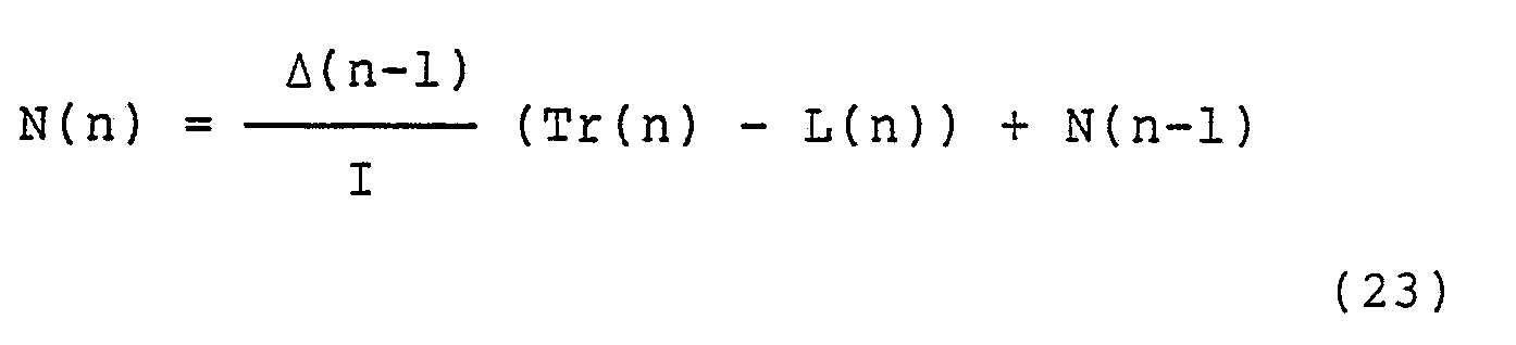
- the ignition time command value N(n / n-1): engine speed predicted value in the stroke n which is predicted based on measured information up to the stroke (n-1 and Tr*(n) : target generated torque.
- the engine speed N can be changed even in one stroke. nowever. a representative value in one stoke is used. There is a possibility of causing a calcuiation error in the formula (4) including an integration of time synchronization due to the use of the above-mentioned representative vaiue. However, in this case, it is only necessary to narrow an integration width ⁇ (n-1) sufficiently. Further. it is also necessary to store in a memory a table of a characteristic pattern of a generated torque vs. gmuon time).
- the problem of predicting the amount of air flowing into the cylinder is to obtain a prediction value m -(n/n-1) of the amount of air flowing into the cylinder in the n-th stroke rationally based on the models of the above formulas (3) - (9), and from the throttle opening degree ⁇ th ( ⁇ )
- these parameters ⁇ , ⁇ , y, and e are included, and it is necessary to estimate these parameters. Further, the engine load L can not be measured actually. However. as compared with a physical quantity which changes for each stroke, the above-mentioned parameters and the engine load L are dependent upon the atmospheric pressure, atmospheric temperature, cylinder wail temperature. dirt of at inlet of manifold, dirt in the air flow meter, block of the fuel supply device (injector), and quality of the fuel. Thus, these parameters change only slowly and may be considered substantially at a constant value. Accordingly, as a variation model changing with time of the above-mentioned parameters may be grasped in the form of the following formula where, ⁇ X is a random variable.
- DC(n-1) [Q in (n-1), Q in(n-2) . Q in (n-3) . Q in (n-4), Q in (n-5), N(n-1), N(n-2).
- u(n-1) [ ⁇ th ( ⁇ )
- the state estimation of the control system shown in Fig. 1 can be achieved by calculating the following formula in accordance with the estimation theory where. K is a gain matrix obtained by the estimation theory.
- the formula (12) has a recurrent structure with respect DC (i
- the state estimation section 101 receives as inputs thereto a measured value (measured vector) y(n-1). an estimate value y (n-1
- the observation matrix 9 is an observation matrix H in the second equation in the formula (11) or in the first equation in the formula (12).
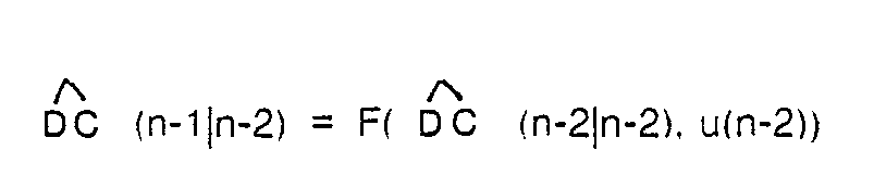
- the prediction section 102 performs the calculation of the second equation in the formula (12) based on the above-mentioned engine state vector estimation value DC (n-1
- a manipulation vector is determined by using the above-mentioned engine state vector estimate value and the engine state prediction vector so as to attain a control target vector DC.
- the formula (3) which is a part of the formula (11). and the formula (10) (x corresponds to a) may be used.
- the throttle opening degree in the n-th stroke is contained in the formulas and since this is unknown in the (n-1 )th stroke. either of the following methods is adopted.
- This prediction value is a value on the time axis. Hence, this value is converted to a crank angle expression. ⁇ th ( ⁇ )
- the accel pedal and the throttle valve are coupled mechanically. If a delay element which is insensible to a driver is introduced in the coupling, and after detecting a change in the movement of the accel pedal, if the throttle angle is predicted based on a coupling transmission characteristic, then a lead time for the prediction will be earned.
- a delay element is introduced in a coupling portion between the accel pedal 3 and the throttle valve 2. If the delay element 4 is realized by an electrical means, it will become possible to predict a throttle angle from a displacement of the accel pedal 3 without fail. When the reliability is considered to be most important, it will be essential to realize by a mechanical means.
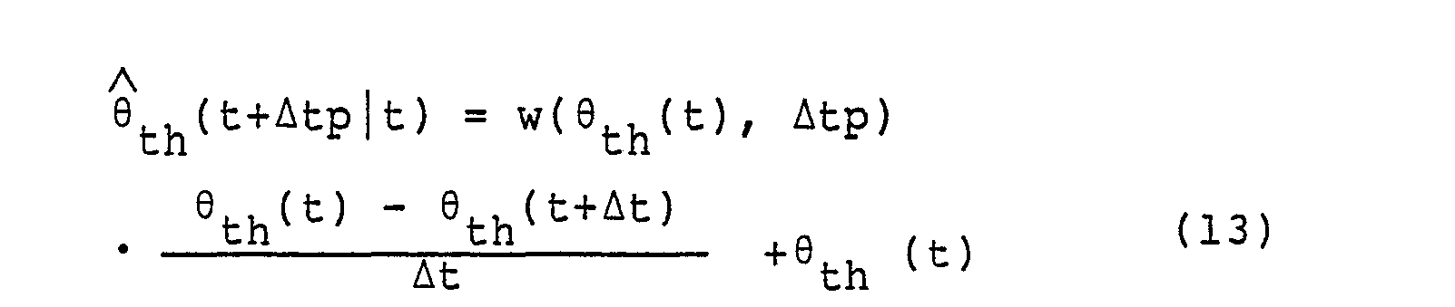
- the accel pedal angle per se may be predicted by a method like the formula (13). Specifically, the accel pedal angle is predicted as in the following formula ⁇
- Fig. 3 shows the overall arrangement of the control system, however, the basic structure is equivalent to that shown in Fig. 1.
- a comparison element 200 is the same as 104 in Fig. 1.
- the state estimate section 201 estimates based on the formula (12) the amount of air flow into the cylinder in -(n-2
- a throttle angle prediction section 203 performs prediction based on the prediction method of the formula (13) using the aforementioned trend values for prediction, or based on the formulas (14) and (15) by introducing the delay element between the accel pedal and the throttle valve.
- a prediction section 204 of the amount of air Q in flowing into the cylinder and the engine speed N predicts the amount of air flowing into the cylinder Q in (n
- a fuel supply quantity and ignition time determining section 202 determines the fuel supply command value Gsk> SUB f and the ignition timing ⁇ adv from the above-mentioned calculated information by using the formulas (8) and (9) so that a target air-fuel ratio A/F*, and a target torque Tr" are attained.
- the amount of calculation is relatively large. As a result, it is impossible in some cases to execute by a small scale arithmetic unit.
- This method is based on a point of view that the amount of air Q, n (n) flowing into the cylinder is determined basically by a throttle angle ⁇ th ( ⁇ )
- the throttle opening degrees up to the (n-1)th stroke are utilized.
- the throttle opening degrees up to the n-th stroke are included as the explanatory factor, and the prediction value obtained by the throttle opening degree predicting method described in the foregoing may be used.
- the calculation load does not become large.
- the air flow measured value Q a y(i) may be added as the explanatory factor. This is useful to take the inertia effect in the air within the manifold into consideration.
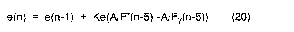
- the output value of the exhaust gas air-fuel ratio sensor is used to correct a coefficient multiplied to the fuel supply command value G f (n). This is based on the view that the reason why the air-fuel ratio is difficult to maintain the target value is due to the blocking in the supply device (injector), and the quality of the fuel.
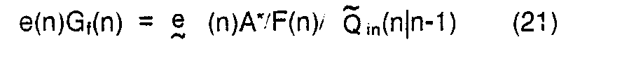
- the correction coefficient e(n) is estimated as in the following formula where, Ke is an estimate gain, and the actual fuel supply command is calculated by
- This method utilizes the fact that the generated torque can be predicted from the estimate value of the amount of air flowing into the cylinder, the fuel injection quantity, and the ignition time in the past. From this result, a change in the engine speed is predicted, and furthermore. it is intended to predict the amount of air flowing into the cylinder by using a throttle opening degree (predicted value). For this purpose, a model relating to each physical quantity is established as follows.
- a cooling water temperature T w is measured in many cases. Accordingly, it is useful in reducing the load of calculation for prediction to set the parameters included in the model formulas in a functional formula of the cooling water temperature Tw or in a table.
- Fig. 4 there is shown a flowchart of a processing procedure when the processing of Fig. 1 is executed by a microprocessor or the like.
- the logic is formed based on a dynamic logical formation as compared with the prior art control logic in which the control is directed to the steady state and at the time of transient, the correction is made in accordance with the situation.
Landscapes
- Engineering & Computer Science (AREA)
- Chemical & Material Sciences (AREA)
- Combustion & Propulsion (AREA)
- Mechanical Engineering (AREA)
- General Engineering & Computer Science (AREA)
- Electrical Control Of Air Or Fuel Supplied To Internal-Combustion Engine (AREA)
- Combined Controls Of Internal Combustion Engines (AREA)
- Control Of Throttle Valves Provided In The Intake System Or In The Exhaust System (AREA)
Abstract
Description
- The present invention relates to a fuel supply control of an engine for automobiles. and in particuiarn to a method of controlling fuel supply suitable for performing the control to maintain an air-fuei (auo at a proper value.
- In a prior art fuel supply control system of the feedback control type, a fundamental fuel supply quantity Ti(n) (usually, given by a valve opening time period of a fuel injection valve) in an an n-th stroke is determined based on an air flow rate Qay(n-1) at the inlet of a manifold measured in an (n-1 )th stroke (n is an integer, and one stroke corresponds to 1.2 revolutions in a 4-cycle engine) and an engine speed N(n-1) as expressed by the following formula

- The determined quantity of fuel is supplied to each cylinder. This fundamental fuel supply quantity Ti(n) is a value when the engine is in a steady state. At the transient time when the throttle valve is opened or closed as during acceleration or deceleration, a correction is made by adding a correction quantity to the fundamental fuel supply quantity. This correction quantity is obtained as a function of the amount of variation Δθth(n-1) with time in the degree of opening of the throttle valve as expressed by the following formula k = 1 + func(Δθth(n-1)) (2).
- and the fuel quantity to be supplied is determined by correctly the Ti(n) in formula (1) by the correction quantity k.
- The calculation method according the formula (1) is to determined the fuel quantity to be supplied in the next n-th stroke by using the measured values including the air flow rate and engine speed in the (n-1)-th stroke. In this method, if the intake air flow rate or engine speed is changed to a great extent between the (n-1 )th stroke and the n-th stroke, the fuel quantity supplied in the n-th stroke with be deviated from a required fuel quantity in the n-th stroke. Thus. the AF ratio (air to fuel ratio) will also be deviated from a target value. The appropriate fuel quantity to be supplied should be a value which matches the amount of air actually flowing into each cylinder in the n-th stroke. However, this amount of air flowing into the cylinder cannot be measured by the technique at the present time. Even if the amount of air flow into the cylinder can be measured, since a delay is involved in the calculation, it results in that the present fuel quantity is calculated based on the amount of air in the past stroke. For this reason, at the transient time, since a significant error is caused in the air-fuel ratio control, it is necessary to design the exhaust gas control device (catalyst, EGR, etc.) with a sufficient margin in the characteristic thereof more than required. Thus. there has been a problem in the cost and the drivability.
- The formula (2) is intended to compeonsate for a follow-up delay in the fuel supply quantity during transient by using a change in the degree of opening of the throttle valve. Practically, however, much time and labor have been spent to experimentally obtain a function of the correction coefficient which satisfies both the reduction and exhaust gas components and the drivability. Although. not less than 50% of the development period of the control logic has been devoted, there is a problem in that the accuracy of control of the air-fuel ratio is still low.
- An object of the present invention is to provide a logical formation for controlling the air-fuel ratio, which is capable of controlling the air-fuel ratio with high accuracy even in a transient state by predicting the amount of air flowing into the cylinder in a future stroke by a novel method. and which enables to adapt the control system to engines of varied types.
- The above object can be achieved by introducing a measure for accurately and rationally predicting the amount of air flowing into the cylinder in an n-th stroke based on measured data in an (n-1 )th stroke and its preceeding strokes. As the measure, it is considered to employ (1) a numerical formula model for prediction, and (2) a method for predicting the amount of air flowing into the cylinder in the n th stroke by introducing into a link mechanism consisting of an accel pedal and a throttle valve, an element Involving a time delay so small as to be insensible to the driver and by utilizing this time delay. In the measure including both items (1) and (2), there is an advantage of making the prediction to be easy by introducing a physical delay element. On the other hand, when only the numerical formula model mentioned in item (1) IS used, there is an advantage in that the control can be realized without modifying at all the hardware structure of the engine control system existing at the present time.
- In either case, it is a basic matter to predict the amount of air flowing into the cylinder according to a numerical formula. However, various methods for predicting the amount of air flowing into the cylinder are considered depending on how the fundamental model for prediction is formed, and further, how the inconsistency between the actual phenomenon and the fundamental model is corrected.
- A prediction logic of the present invention includes a state estimation section and a prediction section. In the state estimation section, a physical quantity in an (n-1 )th stroke required in the prediction section, or parameters which can not be measured are estimated by an object characteristic model and a measured value. In other words, the estimate value is obtained by calculating a measured value of an indirect point parameter.
- The concrete realization of this prediction logic is attained by extensively applying a known Kalman filter or an observer theory. In the prediction section, by using the measured value, and the estimate value obtained in the state estimation section as initial values, the amount of air flowing into the cylinder in an n-th stroke is predicted based on a model representing a characteristic of the amount of air flowing into the cylinder. The quantity of fuel supply in the n-th stroke can be determined by this predicted value of the amount of air flowing into the cylinder and a target air-fuel ratio. By adopting such a logical formation, the measured value in the preceding stroke of the stroke in which the fuel is to be supplied is not used as it is for determining the quantity of fuel supply as in the prior art, but the measured value and the model of the characteristic of the measurement object are utilized collectively. Thus, a physical quantity (e.g., the amount of air flowing into the cylinder) which can not be measured in an on-board control system (e.g., a control system mounted on the actual engine) is estimated and predicted thereby to utilized in determining the fuel quantity. As a result, it is possible to clearly the logical formation for the control and to adapt the control logic to engines of various types, and at the same time, the control of the air-fuel ratio can be achieved with high accuracy.
-
- Fig. 1 is a schematic diagram showing a basic arrangement of an embodiment of the present invention:
- Fig. 2 is a timing chart of measurement and control of physical quantities related to the control of an engine:
- Fig. 3 is a block diagram showing a detailed arrangement of the embodiment; and
- Fig. 4 is a flowchart showing a control procedure when the control shown in Fig. 1 is performed by a microcomputer.
- The embodiments of the present invention will be described with reference to the drawings. As shown in Fig. 1, as a means for measuring a state of an engine, an
air flow meter 1 at a manifold inlet, a crank angle meter 8, and an exhaust gas air-fuel ratio meter 7 are provided, and in addition, athrottle angle meter 2 and an accelpedal angle meter 3 are provided. The signals from these meters are inputted to an engine electronic control unit (not shown), and the calculated results are commanded to an injector 5 and anignition device 6 thereby to perform the control of the engine. - Here. the symbols in the engine system in Fig. 1 are as follows:
- Qay : the amount of air flowing into a manifold.
- θth : a throttle angle,
- θac : an accel pedal angle,
- Gf : a fuel supply command value,
- θadv: an ignition timing,
- eGf : a fuel supply executed value,
- A Fy : an air-fuel ratio measured value,
- N : an engine speed (rpm)
- Tr : a cylinder generated torque, and
- L : an engine load.
- These symbols are also used in Fig. 2 to explain the cause and effect relationships of parameters.
- Fig. 2 shows the cause and effect relationships of the operation parameters of the engine. Specifically. Fig. 2 shows a change in each operation parameter of the engine which is the object of the control in each stroke. Here, one stroke corresponds to 1 revolutions in a 4-cycle engine and represents a range of 180° of the crank angle. The left side items represent principal physical quantities, and it is illustrated how each of these quantities changes in each stroke. For example, the amount of air Qin flowing into the cylinder changes in a wave shape in each stroke. This is because that the ripples of air are caused due to reciprocating motion of a piston in the cylinder or movement of an intake valve. Environmental parameters are dependent upon an atomospheric pressure, atomospheric temperature, quality of fuel, etc., and thus, they change slowly for a period of several strokes shown in Fig. 2, and these parameters may be regarded as approximately constant. The throttle angle θth is shown to begin its opening operation in an (n-1)th stroke. Furthermore, it will be seen from a characteristic showing the injection quantity Gf that the fuel is injected intermittently by the injector. In this manner, the changes in the physical quantities representing the dynamic characteristics of the object engine are shown. In Fig. 2, each of thick solid lines has a starting point marked with a black dot and shows its destination with an arrow -, thereby to indicate the cause and effect relationship for each physical quantity. That is, the black dot means that this black dot is a factor of a change of the physical quantity which is indicated by the arrow originated from the black dot. For example, it is shown that the engine speed N in the n-th stroke is determined by these factors including an engine speed N(n-1) in the (n-1)th stroke, an engine load L(n) in the n-th stroke, and a generated torque Tr in the n-th stroke. This cause and effect relationship can be expressed by the relationship formula such as a formula (4) described later. Similarly, it is also shown that the amount of air (air quantity) Q in(n) flowing into the cylinder in the n-th stroke, the generated torque Tr(n) in the n-th stroke, and the air-fuel ratio measured value A/F(n+2) in the (n+2)th stroke respectively indicated by the tips of arrows are changed by parameters corresponding to black dots which are the origins of the arrows. Furthermore, the injection quantity Gf and the ignition time Qadv are the quantities obtained by the calculation based on the measured values, and they are controlled by the control unit. Accordingly, the starting points of the arrows indicating the Gf and Qadv are in the control arithmetic unit (control unit).
- The control system based on the cause and effect relationships shown in Fig. 2 can be represented by a model in the following manner (where, n is a subscript representing a stroke). In this respect, the engine which is to be represented by a model is a 4-cycle, 4-cylinder engine by way of an example.
- The amount of air flowing into cylinder:

- The engine speed:

- The generated torque:

- The flow meter measured value:

- The air-fuel ratio measured value:

 in(n/n-1): predicted value of flowing into cylinder in the stroke n which is predicted based on measured information in the strokes up to the stroke (n-1).
- The ignition time command value:

- In the model formulas described above. the engine speed N can be changed even in one stroke. nowever. a representative value in one stoke is used. There is a possibility of causing a calcuiation error in the formula (4) including an integration of time synchronization due to the use of the above-mentioned representative vaiue. However, in this case, it is only necessary to narrow an integration width Δ(n-1) sufficiently. Further. it is also necessary to store in a memory a table of a characteristic pattern of a generated torque vs. gmuon time).
- The problem of predicting the amount of air flowing into the cylinder is to obtain a prediction valuem-(n/n-1) of the amount of air flowing into the cylinder in the n-th stroke rationally based on the models of the above formulas (3) - (9), and from the throttle opening degree {θth(τ)|es (i-1)}. engine soeed NO-1 required time for stroke A(i-1), flow meter measured value θa,y(i-1), air-fuel ratio measured iue AF (i-1 fuel supply command value Gf, and ignition time command value θadv(i-1) (where, ≦ m which nave peen measured up to the (n-1)th stroke.
- In the formulas (3) - (9), these parameters α, β, y, and e are included, and it is necessary to estimate these parameters. Further, the engine load L can not be measured actually. However. as compared with a physical quantity which changes for each stroke, the above-mentioned parameters and the engine load L are dependent upon the atmospheric pressure, atmospheric temperature, cylinder wail temperature. dirt of at inlet of manifold, dirt in the air flow meter, block of the fuel supply device (injector), and quality of the fuel. Thus, these parameters change only slowly and may be considered substantially at a constant value. Accordingly, as a variation model changing with time of the above-mentioned parameters may be grasped in the form of the following formula

- When the behavior in the control system is represented by a model in this manner, an estimation theory represented by the Kalman filter can be applied. In order to simplify the expression, such a vector is introduced hereinafter.
- The state quantity:
DC(n-1) = [Qin(n-1), Qin(n-2). Qin(n-3). Qin(n-4), Qin(n-5), N(n-1), N(n-2). Qay(n-1 ), A/Fy(n-1 ), Tr(n-1 ), α(n-1 ), β-(n-1 ), γ(n-1 e(n-3), e(n-5), L(n-1)]T - The external input:
u(n-1) = [{θth(τ)|τ∈θ9(n-1)}, {θm(τ)|τ∈θ(n-1) Δ(n-1), Gf(n-3), θadv(n-1)]τ - The measured value:
y(n-1) = [N(n-1), Qay(n-1),
A/Fy(n-1)]τ - The formulas (3) - (10) can be expressed collectively by using the vectors mentioned above in the following formula

V: variable terms ηX(n-1) for the state quantity and
H: observation matrix. - (Practically, however, since the system is non-linear, the state vectors can not be determined in such a simple manner. Here, with respect to a higher order delay an estimated value which has been obtained heretofore is used as an alternative value.)
- The state estimation of the control system shown in Fig. 1 can be achieved by calculating the following formula in accordance with the estimation theory

 (i|i) with the progress of the strokes. it is possible to obtain an estimate value which utilizes to the maximum extent the information which has been measured heretofore.
- Next, each of the sections shown in Fig. 1 will be described. The
state estimation section 101 receives as inputs thereto a measured value (measured vector) y(n-1). an estimate value y (n-1|n-1) corresponding to a measured vector, and a manipulation vector u(n-2), and calculates in accordance with the formula (12) to obtain the engine state vector estimate value DC (n-1|n-1). Theobservation matrix 9 is an observation matrix H in the second equation in the formula (11) or in the first equation in the formula (12). Theprediction section 102 performs the calculation of the second equation in the formula (12) based on the above-mentioned engine state vector estimation value DC (n-1|n-1) and a manipulation vector U(n-1) (here, the index n-2 becomes n-1), and predictes an engine state prediction vector DC (n|n-1). In the manipulationquantity determination section 103, a manipulation vector is determined by using the above-mentioned engine state vector estimate value and the engine state prediction vector so as to attain a control target vector DC. - In order to predict the air amount flowing into the cylinder, the formula (3) which is a part of the formula (11). and the formula (10) (x corresponds to a) may be used. However, since the throttle opening degree in the n-th stroke is contained in the formulas and since this is unknown in the (n-1 )th stroke. either of the following methods is adopted.
- Since the throttle opening degree changes in most cases linearly, the linear prediction is used. In a concrete way, the prediction is attained by the following formula
-
- θth(t|t'): a throttle opeing degree prediction value at a time t which is predicted by using a measured value up to a time t',
- w(θth(t), Atp): a weighting parameter, and
- Δt : a measurement sampling period of the throttle opening degree.
- (When the prediction value exceeds upper and lower limits, upper and lower limit values are used respectively.) This prediction value is a value on the time axis. Hence, this value is converted to a crank angle expression. {th(τ)|τ∈θ(n)} by the engine speed prediction value N(nln-1) which is determined by the formulas (4) and (5)

- The accel pedal and the throttle valve are coupled mechanically. If a delay element which is insensible to a driver is introduced in the coupling, and after detecting a change in the movement of the accel pedal, if the throttle angle is predicted based on a coupling transmission characteristic, then a lead time for the prediction will be earned. Thus, as shown by the reference numeral 4 in Fig. 1. a delay element is introduced in a coupling portion between the
accel pedal 3 and thethrottle valve 2. If the delay element 4 is realized by an electrical means, it will become possible to predict a throttle angle from a displacement of theaccel pedal 3 without fail. When the reliability is considered to be most important, it will be essential to realize by a mechanical means. In this case, however, it is difficult to realize the complete delay element by the mechanical means. In order to cope with this difficulty, a delay similar to that caused in the integration is introduced. and the accel pedal angle per se may be predicted by a method like the formula (13). Specifically, the accel pedal angle is predicted as in the following formula
- By substituting the above result to θac in the following formula, a prediction value of 8th can be obtained.

- The overall arrangement of the above embodiment is shown in Fig. 3. In Fig. 3, the engine system which is the object of control is the small as in Fig. 1, and since reference numerals 1 - 7 designate identical parts, the descriptions thereof are omitted. Fig. 3 shows the overall arrangement of the control system, however, the basic structure is equivalent to that shown in Fig. 1. In Fig. 3, a
comparison element 200 is the same as 104 in Fig. 1. Astate estimate section 201 in Fig. 3 receives deviations obtained by comparing a measured air-fuel ratio A/Fy(n-1), a measured engine speed N(n-1), and a measured amount of air flowing into the manifold Qay(n-1), respectively with an estimated air-fuel ratio Â,Fy(n-1|n-1), an estimated engine speed(n-1|n-1), and an estimated amount of air flow Qay(n-1|n-1), and also a fuel supply quantity Gf and an ignition timing θadv which are the manipulation quantities are inputted. By using these signals, the
state estimate section 201 estimates based on the formula (12) the amount of air flow into the cylinderin-(n-2|n-1), Q in(n-1|n-1), the effective fuel supply rate e (n-2|n-1), the engine load(n-1|n-1), the parameters which change slowly cod1>â(n-1|n-1), (n-1|n-1), the air-fuel ratio ihat>pA/Fy, the engine speed N, and the amount of air flow into the manifold Qay.
- A throttle
angle prediction section 203 performs prediction based on the prediction method of the formula (13) using the aforementioned trend values for prediction, or based on the formulas (14) and (15) by introducing the delay element between the accel pedal and the throttle valve. Aprediction section 204 of the amount of air Q in flowing into the cylinder and the engine speed N predicts the amount of air flowing into the cylinder Qin(n|n-1), and the engine speed N(nin-1) by using the throttle angle prediction value 9th-(nln-1), the estimate value of the amount of airac(n-1|n-1) flowing into the cylinder, the engine load estimate value L(n-1|n-1), the engine speed estimate value(n-1|n-1), and the parameter estimate values cod1> which have been calculated in the
state estimate section 201. A fuel supply quantity and ignitiontime determining section 202, determines the fuel supply command value Gsk> SUBf and the ignition timing θadv from the above-mentioned calculated information by using the formulas (8) and (9) so that a target air-fuel ratio A/F*, and a target torque Tr" are attained. In the embodiment described above, as will be seen from the formulas defining the control operation, the amount of calculation is relatively large. As a result, it is impossible in some cases to execute by a small scale arithmetic unit. At the time of high engine speeds, since the inertia of the generated torque is large as compared with a change in the engine load, it is feasible, instead of calculating the fuel supply quantity in each stroke, to calculate the fuel supply quantity by suitably sampling the strokes and to provide as a fuel supply command value by holding the calculated fuel supply quantity. However, at the time of low engine speeds, since the inertia of the torque is small, the influence of a change in the engine load which is an external disturbance factor becomes significant. As a result, it is necessary to accurately calculate the fuel supply quantity for each stroke. A simplified method of the above embodiment for enabling, a small scale arithmetic unit to execute will be described hereinafter. - This method is based on a point of view that the amount of air Q,n(n) flowing into the cylinder is determined basically by a throttle angle {θth(τ)|τ∈θ(i)} and an engine speed N(i) (i ≦ n-1). Specifically. It is intended to predict the Qin(n) by the following functional formula


- It is difficult to measure the amount of air flowing into the cylinder by the on-board system. However. the measurement is possible by an experimental device, and by this device, by using the amount of air measured value Qay, throttle opening degree θth, and engine speed N, a functional formula can be obtained as in the following formula

- When the amount of air flowing into the cylinder is calculated posteriorly as in the formula (18), this result in used to obtain the parameter PS1 so that the J(Ps1) in the following formula becomes minimum

- By substituting the parameter PS1 obtained here, it is possible to obtain the amount of air flowing into the cylinder in the n-th stroke. In the formula (16), the throttle opening degrees up to the (n-1)th stroke are utilized. However, the throttle opening degrees up to the n-th stroke are included as the explanatory factor, and the prediction value obtained by the throttle opening degree predicting method described in the foregoing may be used. In this respect, since the calculation of the parameter PS1 which makes the formula (19) minimum is carried out by a recurrent functional formula, the calculation load does not become large. Furthermore, in the formula (16), the air flow measured value Qay(i) may be added as the explanatory factor. This is useful to take the inertia effect in the air within the manifold into consideration.
- The output value of the exhaust gas air-fuel ratio sensor is used to correct a coefficient multiplied to the fuel supply command value Gf(n). This is based on the view that the reason why the air-fuel ratio is difficult to maintain the target value is due to the blocking in the supply device (injector), and the quality of the fuel. The correction coefficient e(n) is estimated as in the following formula
- This method utilizes the fact that the generated torque can be predicted from the estimate value of the amount of air flowing into the cylinder, the fuel injection quantity, and the ignition time in the past. From this result, a change in the engine speed is predicted, and furthermore. it is intended to predict the amount of air flowing into the cylinder by using a throttle opening degree (predicted value). For this purpose, a model relating to each physical quantity is established as follows.
- The amount of air flowing into the cyiinder:


A/Fy(n-1) = p(Qin(n-5), e(n-5)G;(n-5)) (25) - The relationship between the amount of air flowing into the cylinder and the air flow measured value:

- The differences between the method based on the precise model formulas and this simplified method reside in that in the latter, the formula (22) is used only for the prediction of the amount of air flowing into the cylinder and the formula (26) is used to established the relation with respect to the air flow meter measured value, the equation system is formed in the difference type as far as possible and it makes it unnecessary to solve the simultaneous equation, and the parameters to be estimated are reduced to only the load L and the supply effective value e thereby to reduce the load of calculation for prediction. The estimation and prediction based on these equation systems can be performed in a similar manner as in the method described in the foregoing.
- The embodiments are described in the foregoing. In the control system, a cooling water temperature Tw is measured in many cases. Accordingly, it is useful in reducing the load of calculation for prediction to set the parameters included in the model formulas in a functional formula of the cooling water temperature Tw or in a table. In Fig. 4, there is shown a flowchart of a processing procedure when the processing of Fig. 1 is executed by a microprocessor or the like.
- In the present invention, the logic is formed based on a dynamic logical formation as compared with the prior art control logic in which the control is directed to the steady state and at the time of transient, the correction is made in accordance with the situation.
- Therefore in the present invention, the following advantages are provided.
- (1) Heretofore, not less than 50% of the period has been spent to develop the correction method during transient in the engine operation in order to apply the control logic to engines of various types. In the present invention, since the logical formation is clear, such a period can be reduced to a great extent.
- (2) Since the logic itself is formed based on the dynamic phenomenon, the control can be applied to the all region including the steady state and transient state operation of the engine with high controlling performance. Furthermore, the control logic with respect to the transient state can be adapted to the actual apparatus which has been impossible.
Claims (6)
Applications Claiming Priority (2)
| Application Number | Priority Date | Filing Date | Title |
|---|---|---|---|
| JP62084737A JP2810039B2 (en) | 1987-04-08 | 1987-04-08 | Feedforward type fuel supply method |
| JP84737/87 | 1987-04-08 |
Publications (3)
| Publication Number | Publication Date |
|---|---|
| EP0286104A2 true EP0286104A2 (en) | 1988-10-12 |
| EP0286104A3 EP0286104A3 (en) | 1990-02-07 |
| EP0286104B1 EP0286104B1 (en) | 1992-09-16 |
Family
ID=13839010
Family Applications (1)
| Application Number | Title | Priority Date | Filing Date |
|---|---|---|---|
| EP88105571A Expired - Lifetime EP0286104B1 (en) | 1987-04-08 | 1988-04-07 | Method of controlling fuel supply to engine by prediction calculation |
Country Status (5)
| Country | Link |
|---|---|
| US (1) | US4987888A (en) |
| EP (1) | EP0286104B1 (en) |
| JP (1) | JP2810039B2 (en) |
| KR (1) | KR920010307B1 (en) |
| DE (1) | DE3874585T2 (en) |
Cited By (4)
| Publication number | Priority date | Publication date | Assignee | Title |
|---|---|---|---|---|
| GB2216685A (en) * | 1988-03-25 | 1989-10-11 | Fuji Heavy Ind Ltd | Fuel injection control system of automotive engine |
| GB2225877A (en) * | 1988-12-08 | 1990-06-13 | Fuji Heavy Ind Ltd | Fuel injection control system for an automotive engine |
| FR2731050A1 (en) * | 1995-02-28 | 1996-08-30 | Siemens Automotive Sa | Method of quantifying air content of IC engine cylinder |
| CN115103955A (en) * | 2020-02-28 | 2022-09-23 | 罗尔斯·罗伊斯解决方案有限公司 | Method for model-based control and regulation of an internal combustion engine |
Families Citing this family (50)
| Publication number | Priority date | Publication date | Assignee | Title |
|---|---|---|---|---|
| JPH02286851A (en) * | 1989-04-28 | 1990-11-27 | Fuji Heavy Ind Ltd | Fuel injection control device of engine |
| DE3930396C2 (en) * | 1989-09-12 | 1993-11-04 | Bosch Gmbh Robert | METHOD FOR ADJUSTING AIR AND FUEL AMOUNTS FOR A MULTI-CYLINDRICAL INTERNAL COMBUSTION ENGINE |
| FR2659114B1 (en) * | 1990-03-02 | 1994-07-08 | Siemens Automotive Sa | METHOD AND DEVICE FOR CONTROLLING THE RICHNESS OF THE AIR / FUEL MIXTURE OF AN INTERNAL COMBUSTION ENGINE. |
| JP2918624B2 (en) * | 1990-05-29 | 1999-07-12 | 株式会社日立製作所 | Engine fuel injection control method |
| US5029569A (en) * | 1990-09-12 | 1991-07-09 | Ford Motor Company | Method and apparatus for controlling an internal combustion engine |
| US5270935A (en) * | 1990-11-26 | 1993-12-14 | General Motors Corporation | Engine with prediction/estimation air flow determination |
| US5293553A (en) * | 1991-02-12 | 1994-03-08 | General Motors Corporation | Software air-flow meter for an internal combustion engine |
| US5273019A (en) * | 1990-11-26 | 1993-12-28 | General Motors Corporation | Apparatus with dynamic prediction of EGR in the intake manifold |
| US5070846A (en) * | 1990-11-26 | 1991-12-10 | General Motors Corporation | Method for estimating and correcting bias errors in a software air meter |
| US5497329A (en) * | 1992-09-23 | 1996-03-05 | General Motors Corporation | Prediction method for engine mass air flow per cylinder |
| JP3490475B2 (en) * | 1993-03-26 | 2004-01-26 | トヨタ自動車株式会社 | Air-fuel ratio control device for internal combustion engine |
| US5357932A (en) * | 1993-04-08 | 1994-10-25 | Ford Motor Company | Fuel control method and system for engine with variable cam timing |
| US5535135A (en) * | 1993-08-24 | 1996-07-09 | Motorola, Inc. | State estimator based exhaust gas chemistry measurement system and method |
| JPH07293297A (en) * | 1994-04-20 | 1995-11-07 | Hitachi Ltd | Fuel control for internal combustion engine, device therefor and vehicle using it |
| US5595393A (en) * | 1994-08-15 | 1997-01-21 | Batten; James B. | Infant car seat stroller conversion and method therefor |
| US5537977A (en) * | 1995-01-30 | 1996-07-23 | Chrysler Corporation | Method of estimating exhaust gas recirculation in an intake manifold for an internal combustion engine |
| DE19520605C1 (en) * | 1995-06-06 | 1996-05-23 | Daimler Benz Ag | Set-point control of combustion sequence in Otto-cycle IC engine |
| DE19615542C2 (en) * | 1996-04-19 | 1998-05-07 | Daimler Benz Ag | Device for determining the engine load for an internal combustion engine |
| JP3442626B2 (en) * | 1997-10-20 | 2003-09-02 | 三菱電機株式会社 | Fuel injection control device for internal combustion engine |
| US6157894A (en) * | 1997-12-23 | 2000-12-05 | Simmonds Precision Products, Inc. | Liquid gauging using sensor fusion and data fusion |
| US6006604A (en) * | 1997-12-23 | 1999-12-28 | Simmonds Precision Products, Inc. | Probe placement using genetic algorithm analysis |
| US6256679B1 (en) | 1997-12-23 | 2001-07-03 | Simmonds Precision Products, Inc. | Blackboard-centric layered software architecture for an embedded airborne fuel gauging subsystem |
| JPH11280523A (en) * | 1998-03-31 | 1999-10-12 | Sanshin Ind Co Ltd | Control device for cylinder fuel injection type engine |
| DE69929920D1 (en) * | 1998-04-09 | 2006-04-27 | Yamaha Motor Co Ltd | Fuel injection control unit for an internal combustion engine |
| US6170475B1 (en) | 1999-03-01 | 2001-01-09 | Ford Global Technologies, Inc. | Method and system for determining cylinder air charge for future engine events |
| US6460409B1 (en) * | 2000-05-13 | 2002-10-08 | Ford Global Technologies, Inc. | Feed-forward observer-based control for estimating cylinder air charge |
| DE10051963A1 (en) * | 2000-10-20 | 2002-05-02 | Zahnradfabrik Friedrichshafen | Method for evaluating the driver's driving dynamics request for the driving strategy of an automatic / automated transmission |
| DE10110184A1 (en) * | 2001-03-02 | 2002-09-12 | Powitec Intelligent Tech Gmbh | Optimisation control of a thermodynamic process using state comparison and a process model |
| FR2834314B1 (en) * | 2001-12-31 | 2005-01-07 | Peugeot Citroen Automobiles Sa | METHOD OF ESTIMATING THE FUEL WEALTH OF A COMBUSTIBLE MIXTURE CONSUMED BY AN INJECTION ENGINE, USEFUL WHATEVER THE ENGINE REGIME |
| WO2011142038A1 (en) * | 2010-05-10 | 2011-11-17 | トヨタ自動車株式会社 | Control device of internal combustion engine |
| US9291111B2 (en) | 2010-09-16 | 2016-03-22 | Shindengen Electric Manufacturing Co., Ltd. | Engine control unit, engine control system and engine control method |
| US9458779B2 (en) | 2013-01-07 | 2016-10-04 | GM Global Technology Operations LLC | Intake runner temperature determination systems and methods |
| US9382853B2 (en) | 2013-01-22 | 2016-07-05 | GM Global Technology Operations LLC | Cylinder control systems and methods for discouraging resonant frequency operation |
| US9458778B2 (en) * | 2012-08-24 | 2016-10-04 | GM Global Technology Operations LLC | Cylinder activation and deactivation control systems and methods |
| US9534550B2 (en) * | 2012-09-10 | 2017-01-03 | GM Global Technology Operations LLC | Air per cylinder determination systems and methods |
| US10227939B2 (en) | 2012-08-24 | 2019-03-12 | GM Global Technology Operations LLC | Cylinder deactivation pattern matching |
| US9458780B2 (en) | 2012-09-10 | 2016-10-04 | GM Global Technology Operations LLC | Systems and methods for controlling cylinder deactivation periods and patterns |
| US9416743B2 (en) | 2012-10-03 | 2016-08-16 | GM Global Technology Operations LLC | Cylinder activation/deactivation sequence control systems and methods |
| US9719439B2 (en) | 2012-08-24 | 2017-08-01 | GM Global Technology Operations LLC | System and method for controlling spark timing when cylinders of an engine are deactivated to reduce noise and vibration |
| US9638121B2 (en) | 2012-08-24 | 2017-05-02 | GM Global Technology Operations LLC | System and method for deactivating a cylinder of an engine and reactivating the cylinder based on an estimated trapped air mass |
| US9376973B2 (en) | 2012-09-10 | 2016-06-28 | GM Global Technology Operations LLC | Volumetric efficiency determination systems and methods |
| US9650978B2 (en) | 2013-01-07 | 2017-05-16 | GM Global Technology Operations LLC | System and method for randomly adjusting a firing frequency of an engine to reduce vibration when cylinders of the engine are deactivated |
| US9726139B2 (en) | 2012-09-10 | 2017-08-08 | GM Global Technology Operations LLC | System and method for controlling a firing sequence of an engine to reduce vibration when cylinders of the engine are deactivated |
| US9494092B2 (en) | 2013-03-13 | 2016-11-15 | GM Global Technology Operations LLC | System and method for predicting parameters associated with airflow through an engine |
| US9441550B2 (en) | 2014-06-10 | 2016-09-13 | GM Global Technology Operations LLC | Cylinder firing fraction determination and control systems and methods |
| US9341128B2 (en) | 2014-06-12 | 2016-05-17 | GM Global Technology Operations LLC | Fuel consumption based cylinder activation and deactivation control systems and methods |
| US9556811B2 (en) | 2014-06-20 | 2017-01-31 | GM Global Technology Operations LLC | Firing pattern management for improved transient vibration in variable cylinder deactivation mode |
| US9599047B2 (en) | 2014-11-20 | 2017-03-21 | GM Global Technology Operations LLC | Combination cylinder state and transmission gear control systems and methods |
| US10337441B2 (en) | 2015-06-09 | 2019-07-02 | GM Global Technology Operations LLC | Air per cylinder determination systems and methods |
| US10626803B2 (en) * | 2015-10-22 | 2020-04-21 | United Technologies Corporation | Apparatus and method for controlling and monitoring an electro-hydraulic servovalve |
Citations (6)
| Publication number | Priority date | Publication date | Assignee | Title |
|---|---|---|---|---|
| FR2124798A5 (en) * | 1971-01-25 | 1972-09-22 | Bendix Corp | |
| EP0087809A2 (en) * | 1982-03-03 | 1983-09-07 | Hitachi, Ltd. | Electrical fuel injector control |
| US4424568A (en) * | 1980-01-31 | 1984-01-03 | Hitachi, Ltd. | Method of controlling internal combustion engine |
| EP0134547A2 (en) * | 1983-08-08 | 1985-03-20 | Hitachi, Ltd. | Method of fuel injection control in engine |
| EP0152019A2 (en) * | 1984-02-01 | 1985-08-21 | Hitachi, Ltd. | Method for controlling fuel injection for engine |
| EP0185552A2 (en) * | 1984-12-19 | 1986-06-25 | Nippondenso Co., Ltd. | Apparatus for controlling operating state of an internal combustion engine |
Family Cites Families (7)
| Publication number | Priority date | Publication date | Assignee | Title |
|---|---|---|---|---|
| US4562814A (en) * | 1983-02-04 | 1986-01-07 | Nissan Motor Company, Limited | System and method for controlling fuel supply to an internal combustion engine |
| JPS59196930A (en) * | 1983-04-22 | 1984-11-08 | Nissan Motor Co Ltd | Fuel controlling method for internal-combustion engine |
| JPS6043135A (en) * | 1983-08-17 | 1985-03-07 | Mikuni Kogyo Co Ltd | Fuel supply rate controlling method for internal- combustion engine |
| US4732125A (en) * | 1983-12-29 | 1988-03-22 | Nissan Motor Company, Limited | Internal combustion engine output torque control system |
| JPS60169647A (en) * | 1984-02-13 | 1985-09-03 | Toyota Motor Corp | Fuel injection control method of internal-combustion engine |
| JPS62157244A (en) * | 1985-12-28 | 1987-07-13 | Toyota Motor Corp | Air-fuel ratio control device of internal combustion engine |
| JPH0827203B2 (en) * | 1986-01-13 | 1996-03-21 | 日産自動車株式会社 | Engine intake air amount detector |
-
1987
- 1987-04-08 JP JP62084737A patent/JP2810039B2/en not_active Expired - Lifetime
-
1988
- 1988-04-05 US US07/177,970 patent/US4987888A/en not_active Expired - Lifetime
- 1988-04-07 KR KR1019880003885A patent/KR920010307B1/en not_active IP Right Cessation
- 1988-04-07 EP EP88105571A patent/EP0286104B1/en not_active Expired - Lifetime
- 1988-04-07 DE DE8888105571T patent/DE3874585T2/en not_active Expired - Fee Related
Patent Citations (6)
| Publication number | Priority date | Publication date | Assignee | Title |
|---|---|---|---|---|
| FR2124798A5 (en) * | 1971-01-25 | 1972-09-22 | Bendix Corp | |
| US4424568A (en) * | 1980-01-31 | 1984-01-03 | Hitachi, Ltd. | Method of controlling internal combustion engine |
| EP0087809A2 (en) * | 1982-03-03 | 1983-09-07 | Hitachi, Ltd. | Electrical fuel injector control |
| EP0134547A2 (en) * | 1983-08-08 | 1985-03-20 | Hitachi, Ltd. | Method of fuel injection control in engine |
| EP0152019A2 (en) * | 1984-02-01 | 1985-08-21 | Hitachi, Ltd. | Method for controlling fuel injection for engine |
| EP0185552A2 (en) * | 1984-12-19 | 1986-06-25 | Nippondenso Co., Ltd. | Apparatus for controlling operating state of an internal combustion engine |
Cited By (5)
| Publication number | Priority date | Publication date | Assignee | Title |
|---|---|---|---|---|
| GB2216685A (en) * | 1988-03-25 | 1989-10-11 | Fuji Heavy Ind Ltd | Fuel injection control system of automotive engine |
| GB2216685B (en) * | 1988-03-25 | 1992-10-21 | Fuji Heavy Ind Ltd | Fuel injection control system of automotive engine |
| GB2225877A (en) * | 1988-12-08 | 1990-06-13 | Fuji Heavy Ind Ltd | Fuel injection control system for an automotive engine |
| FR2731050A1 (en) * | 1995-02-28 | 1996-08-30 | Siemens Automotive Sa | Method of quantifying air content of IC engine cylinder |
| CN115103955A (en) * | 2020-02-28 | 2022-09-23 | 罗尔斯·罗伊斯解决方案有限公司 | Method for model-based control and regulation of an internal combustion engine |
Also Published As
| Publication number | Publication date |
|---|---|
| DE3874585D1 (en) | 1992-10-22 |
| EP0286104A3 (en) | 1990-02-07 |
| KR880012876A (en) | 1988-11-29 |
| DE3874585T2 (en) | 1993-04-22 |
| JP2810039B2 (en) | 1998-10-15 |
| JPS63253137A (en) | 1988-10-20 |
| KR920010307B1 (en) | 1992-11-26 |
| US4987888A (en) | 1991-01-29 |
| EP0286104B1 (en) | 1992-09-16 |
Similar Documents
| Publication | Publication Date | Title |
|---|---|---|
| EP0286104B1 (en) | Method of controlling fuel supply to engine by prediction calculation | |
| EP0185552B1 (en) | Apparatus for controlling operating state of an internal combustion engine | |
| Chevalier et al. | Predicting the port air mass flow of SI engines in air/fuel ratio control applications | |
| EP0301548B1 (en) | Fuel injection system of an internal combustion engine | |
| Hires et al. | Transient mixture strength excursions—An investigation of their causes and the development of a constant mixture strength fueling strategy | |
| EP0312835B1 (en) | Control apparatus | |
| JP2556964B2 (en) | Idle operation control device for internal combustion engine | |
| KR100413402B1 (en) | Method for measuring air mass inside cylinder of internal combustion engine using model | |
| US4667640A (en) | Method for controlling fuel injection for engine | |
| US7457701B2 (en) | Air quantity estimation apparatus for internal combustion engine | |
| US4467770A (en) | Method and apparatus for controlling the air-fuel ratio in an internal combustion engine | |
| US5277164A (en) | Method and apparatus for control of engine fuel injection | |
| EP0184626B1 (en) | Control method for a fuel injection engine | |
| US7324888B1 (en) | Computationally efficient data-driven algorithms for engine friction torque estimation | |
| JPH0988685A (en) | Air-fuel ratio control device for internal combustion engine | |
| US4971011A (en) | Air and fuel control system for internal combustion engine | |
| JPH081146B2 (en) | Nonlinear feedback control device for internal combustion engine | |
| KR0158880B1 (en) | Fuel injection control method in an engine | |
| EP0387100B1 (en) | Ignition timing control method for an internal combustion engine and apparatus therefor | |
| JPS61191435A (en) | Vehicle speed control device | |
| JPS6375334A (en) | Feedback control method for internal combustion engine | |
| US6223121B1 (en) | Air-to-fuel ratio control device | |
| JPH01211633A (en) | Fuel injection amount control device for internal combustion engine | |
| Almkvist et al. | A study of air to fuel transient response and compensation with different fuels | |
| US20240084755A1 (en) | Real-Time Determination of a Fresh-Air Mass in a Cylinder |
Legal Events
| Date | Code | Title | Description |
|---|---|---|---|
| PUAI | Public reference made under article 153(3) epc to a published international application that has entered the european phase |
Free format text: ORIGINAL CODE: 0009012 |
|
| AK | Designated contracting states |
Kind code of ref document: A2 Designated state(s): DE GB |
|
| PUAL | Search report despatched |
Free format text: ORIGINAL CODE: 0009013 |
|
| AK | Designated contracting states |
Kind code of ref document: A3 Designated state(s): DE GB |
|
| 17P | Request for examination filed |
Effective date: 19900514 |
|
| 17Q | First examination report despatched |
Effective date: 19910115 |
|
| GRAA | (expected) grant |
Free format text: ORIGINAL CODE: 0009210 |
|
| AK | Designated contracting states |
Kind code of ref document: B1 Designated state(s): DE GB |
|
| REF | Corresponds to: |
Ref document number: 3874585 Country of ref document: DE Date of ref document: 19921022 |
|
| PLBE | No opposition filed within time limit |
Free format text: ORIGINAL CODE: 0009261 |
|
| STAA | Information on the status of an ep patent application or granted ep patent |
Free format text: STATUS: NO OPPOSITION FILED WITHIN TIME LIMIT |
|
| 26N | No opposition filed | ||
| REG | Reference to a national code |
Ref country code: GB Ref legal event code: IF02 |
|
| PGFP | Annual fee paid to national office [announced via postgrant information from national office to epo] |
Ref country code: GB Payment date: 20030326 Year of fee payment: 16 |
|
| PGFP | Annual fee paid to national office [announced via postgrant information from national office to epo] |
Ref country code: DE Payment date: 20030605 Year of fee payment: 16 |
|
| PG25 | Lapsed in a contracting state [announced via postgrant information from national office to epo] |
Ref country code: GB Free format text: LAPSE BECAUSE OF NON-PAYMENT OF DUE FEES Effective date: 20040407 |
|
| PG25 | Lapsed in a contracting state [announced via postgrant information from national office to epo] |
Ref country code: DE Free format text: LAPSE BECAUSE OF NON-PAYMENT OF DUE FEES Effective date: 20041103 |
|
| GBPC | Gb: european patent ceased through non-payment of renewal fee |