EP0285165A2 - Wide area cordless telephone system having means for avoiding double registrations - Google Patents
Wide area cordless telephone system having means for avoiding double registrations Download PDFInfo
- Publication number
- EP0285165A2 EP0285165A2 EP88105290A EP88105290A EP0285165A2 EP 0285165 A2 EP0285165 A2 EP 0285165A2 EP 88105290 A EP88105290 A EP 88105290A EP 88105290 A EP88105290 A EP 88105290A EP 0285165 A2 EP0285165 A2 EP 0285165A2
- Authority
- EP
- European Patent Office
- Prior art keywords
- telephone
- local area
- access
- cordless
- home position
- Prior art date
- Legal status (The legal status is an assumption and is not a legal conclusion. Google has not performed a legal analysis and makes no representation as to the accuracy of the status listed.)
- Granted
Links
Images


Classifications
-
- H—ELECTRICITY
- H04—ELECTRIC COMMUNICATION TECHNIQUE
- H04M—TELEPHONIC COMMUNICATION
- H04M3/00—Automatic or semi-automatic exchanges
-
- H—ELECTRICITY
- H04—ELECTRIC COMMUNICATION TECHNIQUE
- H04W—WIRELESS COMMUNICATION NETWORKS
- H04W84/00—Network topologies
- H04W84/02—Hierarchically pre-organised networks, e.g. paging networks, cellular networks, WLAN [Wireless Local Area Network] or WLL [Wireless Local Loop]
- H04W84/10—Small scale networks; Flat hierarchical networks
- H04W84/16—WPBX [Wireless Private Branch Exchange]
-
- H—ELECTRICITY
- H04—ELECTRIC COMMUNICATION TECHNIQUE
- H04M—TELEPHONIC COMMUNICATION
- H04M1/00—Substation equipment, e.g. for use by subscribers
- H04M1/72—Mobile telephones; Cordless telephones, i.e. devices for establishing wireless links to base stations without route selection
-
- H—ELECTRICITY
- H04—ELECTRIC COMMUNICATION TECHNIQUE
- H04M—TELEPHONIC COMMUNICATION
- H04M7/00—Arrangements for interconnection between switching centres
-
- H—ELECTRICITY
- H04—ELECTRIC COMMUNICATION TECHNIQUE
- H04W—WIRELESS COMMUNICATION NETWORKS
- H04W60/00—Affiliation to network, e.g. registration; Terminating affiliation with the network, e.g. de-registration
-
- H—ELECTRICITY
- H04—ELECTRIC COMMUNICATION TECHNIQUE
- H04W—WIRELESS COMMUNICATION NETWORKS
- H04W74/00—Wireless channel access, e.g. scheduled or random access
-
- H—ELECTRICITY
- H04—ELECTRIC COMMUNICATION TECHNIQUE
- H04W—WIRELESS COMMUNICATION NETWORKS
- H04W76/00—Connection management
- H04W76/10—Connection setup
-
- H—ELECTRICITY
- H04—ELECTRIC COMMUNICATION TECHNIQUE
- H04W—WIRELESS COMMUNICATION NETWORKS
- H04W88/00—Devices specially adapted for wireless communication networks, e.g. terminals, base stations or access point devices
- H04W88/08—Access point devices
Definitions
- the present invention relates to a wide area cordless telephone system.
- a cordless telephone system which comprises a stationary access unit to which a telephone line from a switching system is connected and a transportable cordless unit which establishes a two-way radio channel to the access unit as long as it stays within a specified range.
- a wide area cordless telephone system has recently been proposed to provide wide area services for corporate premises as part of PBX (private branch exchange) telephones.
- PBX private branch exchange
- the whole area of the system is divided into a plurality of local areas and a plurality of fixed access units are located in each local area to establish a radio channel to home position cordless telephones that belong to the own local area as well as to non-home position cordless telephones that enters the own local area.
- the home position cordless telephones have corresponding line terminals in the associated PBX or in the public switched telephone network.
- Each cordless telephone has a multi-channel access capability to have access to any of the access units and includes a manually operated key that is operated by the user when a request is made for registration of the location of his telephone.
- a pre-dialing switching stage is provided in each local area to establish a connection between each access unit and a line terminal of PBX or public switched network so that the telephones can be connected to their corresponding line terminals of the PBX or switched network before dialing procedure begins.
- a controller is provided to register the cordless telephones which are located in the own local area. In order to allow cordless telephones to roam from one area to another, line terminals of the PBX or public switched network are reserved and the controller assigns a reserved line terminal to an entering non-home position telephone and communicates this fact to other local areas.
- the wide area cordless telephone system of the present invention covers a service area which is divided into a plurality of local areas.
- a plurality of home position portable, multi-channel access cordless telephones belong to each local area and have corresponding line terminals in a telephone switching system.
- Each cordless telephone establishes a two-way radio link and transmits a registration request identifying the own telephone through the established radio link upon a manual command.
- the requesting telephone On receiving a response identifying a local area, the requesting telephone returns an acknowlegement identifying the same local area as identified by the received response.
- a plurality of fixed access units are located in each local area to define a plurality of access zones and establish radio links with the home position cordless telephones as well as non-home position cordless telephones belonging to another local area.
- a pre-dialing switching stage is provided in each local area to set up connections between line terminals of the telephone switching system and the access units.
- the pre-dialing switching stage includes a controller which receives the registration request and acknowledgement to control a matrix switch. On receiving a registration request, the controller transmits a response identifying the own local area through the access unit through which it has received the request, assigns a reserved line terminal of the telephone switching system to a cordless telephone if it is identified as belonging to another local area, and on receiving an acknowledgement, makes registration of a cordless telephone if this acknowledgement identifies the same local area as identified by the response.
- the acknowledgement it transmits contains the identification of only one local area even though there is a response of lower signal level from an undesired adjacent local area.
- a wide area cordless telephone system of the present invention is shown.
- the system covers a wide area which is divided into a plurality of local service areas, only two of which are shown in Fig. 1 for simplicity.
- Each local area may be a premises of a corporate division and is divided into a plurality of access zones Z as represented by a dotted circles Z1 and Z2.
- a plurality of home-position portable cordless telephones 1-1 through 1-m are located and have their corresponding PBX line terminals in a PBX (private branch exchange) 5 to which other PBX telephones 7 may be connected.
- PBX 5 is connected to the public switched telephone network 8 via subscriber lines 6 in a conventional manner.
- each access zone is a fixed radio access unit, or transceiver 2 and each cordless telephone 1 has a multi-channel access capability to access any of the access units 2-1 through 2-l and to access any of a plurality of access units of other local areas when it is located in such areas.
- Each access unit 2 has a multi-channel access facility to access any of the cordless telephones roaming within the own access zone by establishing a two-way radio link with it through a control channel.
- Access units 2-1 through 2-l are connected to "l" access line terminals of a pre-dialing switching stage 3 which establishes connections between the "l" access line terminals and "n" line terminals 4-1 through 4-n of PBX 5 before dialing begins.
- the local area B is divided into a plurality of access zones in each of which is located an access unit 12.
- a plurality of home-position portable cordless telephones 11-1 through 11-j belong to the local area B and have their corresponding PBX line terminals in a PBX 15 to which other PBX telephones 17 may be connected.
- PBX 15 is connected to the public switched telephone network 8 via subscriber lines 16.
- Each cordless telephone 11 has a multi-channel access capability to access any of access units 12-1 through 12-j and to access any of a plurality of access units of other local areas when it is located in such areas.
- Each access units 12 has a multi-channel access facility as access units 2 to establish a two-way radio link with a cordless telephone 11 located in the own access zone.
- Access units 12-1 through 12-j are connected to "j" access line terminals of a pre-dialing switching stage 13 which establishes connections between the "j" access line terminals and "k" line terminals 14-1 to 14-k of PBX 15 before dialing takes place.
- Intra-PBX connections are established between cordless telephones of the same local area via the associated PBX and inter-PBx connections are established by way of the public switched telephone network 8. It is to be noted that the pre-dialing switching stages 3 and 13 may be connected directly to subscriber line terminals of the public switched network 8.
- "n” PBX access lines “m” PBX access lines are assigned permanently to the “m” cordless telephones 1 respectively and the “n-m” PBX access lines are reserved for temporary use with the non-home position telphone which roams into the local area A.
- "j" PBX access lines are assigned permanently to the "j" cordless telephones 11 respectively and the "k-j" PBX access lines are reserved for temporary use with the non-home position cordless telephone roaming into the local area B.
- each of the cordless telephones 1 and 11 comprises a multi-channel access transceiver 20 and antenna 21 connected to it through duplexer 22.
- Transceiver 20 is controlled by a controller 24 and exchanges speech signals with a handset 23 and control signals with controller 24.
- Any of the cordless telephones establishes a two-way frequency modulation radio channel with any of the access units 2-1 to 2-l and 12-1 to 12-i.
- a manually operated registration switch 25 is connected to the controller 24. As will be described later, the operation of this switch causes the controller 24 to generate a registration request signal identifying the own telephone and transmit it to nearby access units to elicit a response that identifies the local area of such access units. On receiving such a response, the controllere 24 generates an acknowledgement signal identifying the same local area as identified by the response and returns it to the nearby access units in order to allow registration to be made only in a local area in which the requesting telephone is located.
- a programmable read only memory 26 is connected to the controller 24. This memory stores a local area code identifying the local area in which the home position telephone is located and a telephone number identifying that telephone.
- the data stored in the memory 26 are recalled in response to the operation of the registration switch 25 so that they are contained in the registration request signal.
- a random access memory 27 which stores an access unit identification that identifies the access unit with which the telephone has established a radio link and a new local area code identifying the local area in which the telephone is registered.
- a hook switch 28 is operated in response to the handset 23 going off-hook to cause the controller 24 to read data from the random access memory 27 to generate a call request signal when a call is to be originated.
- each access unit 2 (12) comprises a read only memory 30 in which an access unit code identifying the own access unit and an area code identifying the own local area are stored. Data stored in the memory 30 are recalled by a controller 32 when the access unit receives a call request signal or registration request signal and the recalled data are appended to a signal to be sent to the concentrator.
- the telephone number of the cordless telephone with which the own access unit has established a link is stored in a random access memory 31. This memory is recalled by the controller 32 whenever a call is originated or terminated. Controller 32 is connected by data and control lines to a transceiver 33 to which an antenna 34 is connected through a duplexer 35. Transceiver 33 establishes a two-way frequency modulation radio channel with any of the cordless telephones. A hybrid 36 is connected to the transceiver 33 to provide 2-wire 4-wire conversion between the transceiver 33 and an input terminal of the line concentrator 3 or 13. Controller 32 is also connected to the input terminal of the concentrator through a modem 37.
- Each of the pre-dialing switching stages 3 and 13 comprises a matrix switch 40 having an array of line terminals connected by a line interface circuit 41 to the associated access units 2 (or 12) and an array of PBX line terminals connected by a PBX interface circuit 42 to the PBX access lines of the associated PBX.
- a controller 43 establishes a path in the matrix switch 40 between a PBX line terminal and a multi-frequency sender 44 in response to a call request signal which it receives through the line interface circuit 41 and passes dialed information to the sender 44 to send out a multi-frequency dialing signal to the PBX 5 (15).
- controller 43 disconnects the sender 44 and connects the line terminal of the calling telephone to the associated PBX line terminal.
- An incoming call request from the PBX is also applied to the controller 43 to establish a ringing connection through the matrix 40 to a called telephone.
- a registration request signal sent from any cordless telephone is likely to be received by more than one access unit 2 (12) with varying input levels.
- the received signals are applied through the line interface circuit 41 to the controller 43.
- Controller 43 selects one of the signals having the highest input level and identifies the requesting telephone transmitting it and the access unit through which it has been received, recognizing the location of this cordless telephone. Controller 43 then transmits a response indicating that the registration request has been granted.
- the response signal is received by the requesting telephone, whereupon it sends out an acknowledgement signal to the access unit.
- the controller 43 receives the acknowledgement signal, it creates a record in a position management table 45 indicating a relational link between a file storing the identification of the requesting telephone and a file storing the identification of that access unit.
- the controller 43 When a non-home position telephone is entering the own local area and requesting a registration, the controller 43 identifies this telephone and an access unit through which the request is received and accesses a roamer admission table 46 to determine if the number of such non-home position telephones is not in excess of a limit which in the local area A corresponds to the n-m reserved PBX lines 4 and in the area B corresponds to the k-j commonly used PBX lines 14. If it is, the controller 43 assigns one of the reserved PBX lines to the roaming telephone and transmits a response signal, granting the registration request and indicating the assigned PBX telephone number.
- the controller 43 In response to an acknowledgement from the requesting roaming telephone, the controller 43 creates a record in a roamer management table 47 indicating a relational link between a file storing the identification of the roaming telephone, a second file storing the identification of the access unit relaying the signals and a third file storing the PBX telephone number just assigned to that telephone.
- Roamer management table 47 is consulted by the controller 43 every time an outgoing call is originated from the registered roaming telephone or an incoming call is terminated thereto. Controller 43 now proceeds to communicate the newly assigned PBX telephone number to the controller 43 of the other local area via the switched telephone network 8, for example, to permit incoming calls to be forwarded to the right destination.
- a registration request signal is transmitted (block 51) and received by a access unit (block 52).
- the request signal contains the identification of the telephone, which is examined by the controller 43 to determine if the requesting telephone belongs to the own local area or another local area (block 53). If the requesting telephone is a non-home position telephone, the controller checks for the presence of an idle reserved line in the commonly used PBX lines.
- a response signal is returned to the telephone indicating that the request is not granted (block 55), and if there is one, an idle PBX line is assigned to the telephone (block 56) and a response signal is returned indicating the line number of the assigned PBX line terminal (block 55).
- the response signal is received by the requesting telephone (block 57)
- it sends an acknowledgement signal including the same area identification code as contained in the response (block 58).
- the acknowledgement signal is received by the controller 43 (block 59), it proceeds to register the requesting telephone in the roamer management table 47.
- a roaming cordless telephone 1-m for example, (Fig. 1) is initially located within the service zone Z1 of the access unit 2-l. Assume that it entered the service zone Z2 of the access unit 12-i, crossing the boundary between local areas A and B, and the user depressed the registration key 25, a registration request signal is transmitted and received by the access unit 12-i. Since it is likely that this request signal is also received by the access unit 2-l because of its relaltive proximity to the telephone 1-m, the controller 43 will also return a response granting permission to the request. If there is an idle line in the PBX 15 for the telephone 1-m, the request is granted and a response containing the identification of the local area B is returned.
- the access unit 12-i since the access unit 12-i is closer to the telephone 1-m than the access unit 2-l is, the response signal from access unit 12-i will be received by the telelphone 1-m with a higher input level than the signal it receives from access unit 2-l. Since the carrier is modulated in frequency, weaker signals are completely masked by the stronger signal. Telephone 1-m thus returns an acknowledgement signal including the identification of the local area as contained in the response received from the access unit 12-i. Controller 43 of local area B proceeds to create a record for the telephone 1-m in the roamer management table 47. Failing to receive an acknowledgement, controller 43 of local area A does not proceed to create a registration record in the position managment table 45.
Abstract
Description
- The present invention relates to a wide area cordless telephone system.
- A cordless telephone system is known which comprises a stationary access unit to which a telephone line from a switching system is connected and a transportable cordless unit which establishes a two-way radio channel to the access unit as long as it stays within a specified range.
- A wide area cordless telephone system has recently been proposed to provide wide area services for corporate premises as part of PBX (private branch exchange) telephones. According to the proposed scheme, the whole area of the system is divided into a plurality of local areas and a plurality of fixed access units are located in each local area to establish a radio channel to home position cordless telephones that belong to the own local area as well as to non-home position cordless telephones that enters the own local area. The home position cordless telephones have corresponding line terminals in the associated PBX or in the public switched telephone network. Each cordless telephone has a multi-channel access capability to have access to any of the access units and includes a manually operated key that is operated by the user when a request is made for registration of the location of his telephone. Since the cordless telephones can access any of the access units, a pre-dialing switching stage is provided in each local area to establish a connection between each access unit and a line terminal of PBX or public switched network so that the telephones can be connected to their corresponding line terminals of the PBX or switched network before dialing procedure begins. A controller is provided to register the cordless telephones which are located in the own local area. In order to allow cordless telephones to roam from one area to another, line terminals of the PBX or public switched network are reserved and the controller assigns a reserved line terminal to an entering non-home position telephone and communicates this fact to other local areas.
- However, if a cordless telephone crossing a boundary between adjacent local areas sends a registration request to elicit a response, there is a likelihood of the request being received simultaneously by two or more access units of the adjacent areas and plural responses are returned which indicate the grant of registration in respective local areas, thus resulting in "double" registrations.
- It is therefore an object of the present invention to provide a wide area cordless telephone system which avoids double registrations of a record concerning a roaming cordless telephone.
- To accomplish this object, the wide area cordless telephone system of the present invention covers a service area which is divided into a plurality of local areas. A plurality of home position portable, multi-channel access cordless telephones belong to each local area and have corresponding line terminals in a telephone switching system. Each cordless telephone establishes a two-way radio link and transmits a registration request identifying the own telephone through the established radio link upon a manual command. On receiving a response identifying a local area, the requesting telephone returns an acknowlegement identifying the same local area as identified by the received response. A plurality of fixed access units are located in each local area to define a plurality of access zones and establish radio links with the home position cordless telephones as well as non-home position cordless telephones belonging to another local area. A pre-dialing switching stage is provided in each local area to set up connections between line terminals of the telephone switching system and the access units. The pre-dialing switching stage includes a controller which receives the registration request and acknowledgement to control a matrix switch. On receiving a registration request, the controller transmits a response identifying the own local area through the access unit through which it has received the request, assigns a reserved line terminal of the telephone switching system to a cordless telephone if it is identified as belonging to another local area, and on receiving an acknowledgement, makes registration of a cordless telephone if this acknowledgement identifies the same local area as identified by the response.
- Since the desired access unit is usually closest to the requesting telephone and its reception sensitivity is such that the signal having the highest level has the effect of masking weaker signals, the acknowledgement it transmits contains the identification of only one local area even though there is a response of lower signal level from an undesired adjacent local area.
- The present invention will be described in further detail with reference to the accompanying drawings, in which:
- Fig. 1 is a block diagram of a wide area cordless telephone system of the present invention;
- Fig. 2 is a block diagram of a cordless telephone employed in the present invention;
- Fig. 3 is a block diagram of a pre-dialing switching stage and an access unit of Fig. 1; and
- Fig. 4 is a flowchart useful for a better understanding of the present invention.
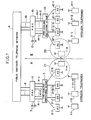
- Referring now to Fig. 1, a wide area cordless telephone system of the present invention is shown. The system covers a wide area which is divided into a plurality of local service areas, only two of which are shown in Fig. 1 for simplicity. Each local area may be a premises of a corporate division and is divided into a plurality of access zones Z as represented by a dotted circles Z1 and Z2. In the local area A, a plurality of home-position portable cordless telephones 1-1 through 1-m are located and have their corresponding PBX line terminals in a PBX (private branch exchange) 5 to which other PBX telephones 7 may be connected. PBX 5 is connected to the public switched
telephone network 8 via subscriber lines 6 in a conventional manner. In each access zone is a fixed radio access unit, ortransceiver 2 and eachcordless telephone 1 has a multi-channel access capability to access any of the access units 2-1 through 2-ℓ and to access any of a plurality of access units of other local areas when it is located in such areas. Eachaccess unit 2 has a multi-channel access facility to access any of the cordless telephones roaming within the own access zone by establishing a two-way radio link with it through a control channel. Access units 2-1 through 2-ℓ are connected to "ℓ" access line terminals of apre-dialing switching stage 3 which establishes connections between the "ℓ" access line terminals and "n" line terminals 4-1 through 4-n ofPBX 5 before dialing begins. - In a similar manner, the local area B is divided into a plurality of access zones in each of which is located an
access unit 12. A plurality of home-position portable cordless telephones 11-1 through 11-j belong to the local area B and have their corresponding PBX line terminals in aPBX 15 to whichother PBX telephones 17 may be connected. PBX 15 is connected to the public switchedtelephone network 8 viasubscriber lines 16. Eachcordless telephone 11 has a multi-channel access capability to access any of access units 12-1 through 12-j and to access any of a plurality of access units of other local areas when it is located in such areas. Eachaccess units 12 has a multi-channel access facility asaccess units 2 to establish a two-way radio link with acordless telephone 11 located in the own access zone. Access units 12-1 through 12-j are connected to "j" access line terminals of apre-dialing switching stage 13 which establishes connections between the "j" access line terminals and "k" line terminals 14-1 to 14-k ofPBX 15 before dialing takes place. - Intra-PBX connections are established between cordless telephones of the same local area via the associated PBX and inter-PBx connections are established by way of the public switched
telephone network 8. It is to be noted that thepre-dialing switching stages network 8. - Among the "n" PBX access lines, "m" PBX access lines are assigned permanently to the "m"
cordless telephones 1 respectively and the "n-m" PBX access lines are reserved for temporary use with the non-home position telphone which roams into the local area A. Likewise, among the "k" PBX access lines, "j" PBX access lines are assigned permanently to the "j"cordless telephones 11 respectively and the "k-j" PBX access lines are reserved for temporary use with the non-home position cordless telephone roaming into the local area B. - As shown in Fig. 2, each of the
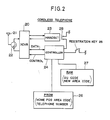
cordless telephones multi-channel access transceiver 20 andantenna 21 connected to it throughduplexer 22.Transceiver 20 is controlled by acontroller 24 and exchanges speech signals with ahandset 23 and control signals withcontroller 24. Any of the cordless telephones establishes a two-way frequency modulation radio channel with any of the access units 2-1 to 2-ℓ and 12-1 to 12-i. - A manually operated
registration switch 25 is connected to thecontroller 24. As will be described later, the operation of this switch causes thecontroller 24 to generate a registration request signal identifying the own telephone and transmit it to nearby access units to elicit a response that identifies the local area of such access units. On receiving such a response, thecontrollere 24 generates an acknowledgement signal identifying the same local area as identified by the response and returns it to the nearby access units in order to allow registration to be made only in a local area in which the requesting telephone is located. A programmable read onlymemory 26 is connected to thecontroller 24. This memory stores a local area code identifying the local area in which the home position telephone is located and a telephone number identifying that telephone. The data stored in thememory 26 are recalled in response to the operation of theregistration switch 25 so that they are contained in the registration request signal. Further connected to thecontroller 24 is arandom access memory 27 which stores an access unit identification that identifies the access unit with which the telephone has established a radio link and a new local area code identifying the local area in which the telephone is registered. Ahook switch 28 is operated in response to thehandset 23 going off-hook to cause thecontroller 24 to read data from therandom access memory 27 to generate a call request signal when a call is to be originated. - In Fig. 3, each access unit 2 (12) comprises a read
only memory 30 in which an access unit code identifying the own access unit and an area code identifying the own local area are stored. Data stored in thememory 30 are recalled by acontroller 32 when the access unit receives a call request signal or registration request signal and the recalled data are appended to a signal to be sent to the concentrator. - The telephone number of the cordless telephone with which the own access unit has established a link is stored in a
random access memory 31. This memory is recalled by thecontroller 32 whenever a call is originated or terminated.Controller 32 is connected by data and control lines to atransceiver 33 to which anantenna 34 is connected through aduplexer 35.Transceiver 33 establishes a two-way frequency modulation radio channel with any of the cordless telephones. Ahybrid 36 is connected to thetransceiver 33 to provide 2-wire 4-wire conversion between thetransceiver 33 and an input terminal of theline concentrator Controller 32 is also connected to the input terminal of the concentrator through amodem 37. - Each of the
pre-dialing switching stages matrix switch 40 having an array of line terminals connected by aline interface circuit 41 to the associated access units 2 (or 12) and an array of PBX line terminals connected by aPBX interface circuit 42 to the PBX access lines of the associated PBX. Acontroller 43 establishes a path in thematrix switch 40 between a PBX line terminal and amulti-frequency sender 44 in response to a call request signal which it receives through theline interface circuit 41 and passes dialed information to thesender 44 to send out a multi-frequency dialing signal to the PBX 5 (15). When the MF dialing signal has been transmitted,controller 43 disconnects thesender 44 and connects the line terminal of the calling telephone to the associated PBX line terminal. An incoming call request from the PBX is also applied to thecontroller 43 to establish a ringing connection through thematrix 40 to a called telephone. - A registration request signal sent from any cordless telephone is likely to be received by more than one access unit 2 (12) with varying input levels. The received signals are applied through the
line interface circuit 41 to thecontroller 43.Controller 43 selects one of the signals having the highest input level and identifies the requesting telephone transmitting it and the access unit through which it has been received, recognizing the location of this cordless telephone.Controller 43 then transmits a response indicating that the registration request has been granted. The response signal is received by the requesting telephone, whereupon it sends out an acknowledgement signal to the access unit. When thecontroller 43 receives the acknowledgement signal, it creates a record in a position management table 45 indicating a relational link between a file storing the identification of the requesting telephone and a file storing the identification of that access unit. - When a non-home position telephone is entering the own local area and requesting a registration, the
controller 43 identifies this telephone and an access unit through which the request is received and accesses a roamer admission table 46 to determine if the number of such non-home position telephones is not in excess of a limit which in the local area A corresponds to the n-m reservedPBX lines 4 and in the area B corresponds to the k-j commonly used PBX lines 14. If it is, thecontroller 43 assigns one of the reserved PBX lines to the roaming telephone and transmits a response signal, granting the registration request and indicating the assigned PBX telephone number. In response to an acknowledgement from the requesting roaming telephone, thecontroller 43 creates a record in a roamer management table 47 indicating a relational link between a file storing the identification of the roaming telephone, a second file storing the identification of the access unit relaying the signals and a third file storing the PBX telephone number just assigned to that telephone. Roamer management table 47 is consulted by thecontroller 43 every time an outgoing call is originated from the registered roaming telephone or an incoming call is terminated thereto.Controller 43 now proceeds to communicate the newly assigned PBX telephone number to thecontroller 43 of the other local area via the switchedtelephone network 8, for example, to permit incoming calls to be forwarded to the right destination. - For a better understanding of the operation of the system, reference is made to Fig. 4. When the
registration key 25 of a cordless telephone is depressed (block 50), a registration request signal is transmitted (block 51) and received by a access unit (block 52). The request signal contains the identification of the telephone, which is examined by thecontroller 43 to determine if the requesting telephone belongs to the own local area or another local area (block 53). If the requesting telephone is a non-home position telephone, the controller checks for the presence of an idle reserved line in the commonly used PBX lines. If there is none, a response signal is returned to the telephone indicating that the request is not granted (block 55), and if there is one, an idle PBX line is assigned to the telephone (block 56) and a response signal is returned indicating the line number of the assigned PBX line terminal (block 55). When the response signal is received by the requesting telephone (block 57), it sends an acknowledgement signal including the same area identification code as contained in the response (block 58). When the acknowledgement signal is received by the controller 43 (block 59), it proceeds to register the requesting telephone in the roamer management table 47. - The advantage of the present invention can be appreciated when a telephone enters an adjacent local area. When a roaming cordless telephone 1-m, for example, (Fig. 1) is initially located within the service zone Z1 of the access unit 2-ℓ. Assume that it entered the service zone Z2 of the access unit 12-i, crossing the boundary between local areas A and B, and the user depressed the
registration key 25, a registration request signal is transmitted and received by the access unit 12-i. Since it is likely that this request signal is also received by the access unit 2-ℓ because of its relaltive proximity to the telephone 1-m, thecontroller 43 will also return a response granting permission to the request. If there is an idle line in thePBX 15 for the telephone 1-m, the request is granted and a response containing the identification of the local area B is returned. However, since the access unit 12-i is closer to the telephone 1-m than the access unit 2-ℓ is, the response signal from access unit 12-i will be received by the telelphone 1-m with a higher input level than the signal it receives from access unit 2-ℓ. Since the carrier is modulated in frequency, weaker signals are completely masked by the stronger signal. Telephone 1-m thus returns an acknowledgement signal including the identification of the local area as contained in the response received from the access unit 12-i.Controller 43 of local area B proceeds to create a record for the telephone 1-m in the roamer management table 47. Failing to receive an acknowledgement,controller 43 of local area A does not proceed to create a registration record in the position managment table 45.
Claims (4)
a plurality of home position portable cordless telephones belonging to the own local area, each of said home position cordless telephones having a corresponding line terminal in a telephone switching system and multi-channnel access means for establishing a two-way radio link, transmitting a registration request through the established links upon a manual command and subsequently transmitting an acknowlegement upon receipt of a response identifying a local area, said request identifying the own cordless telephone;
a plurality of access units for establishing said radio links with said home position cordless telephones and non-home position cordless telephones belonging to another local area; and
a pre-dialing switching stage for establishing a connection between said access units and line terminals of said telephone switching system, said switching stage including control means connected to said access units for receiving said request and acknowledgement therethrough, transmitting a response identifying the own local area through one of said access units on receiving a registration request and assigning a reserved line terminal of said telephone switching system to a non-home position cordless telephone if the same is identified by the received request, and making registration of a cordless telephone on receiving an acknowledgement identifying the same local area as identified by said transmitted response.
a public switched telephone network; and
a private branch exchange provided in one or more of said local areas, said private branch exchange being connected to said switched telephone network, wherein said control means assigns a line terminal of said private branch exchange to a non-home position cordless telephone entering the own local area of said control means.
Applications Claiming Priority (2)
| Application Number | Priority Date | Filing Date | Title |
|---|---|---|---|
| JP83586/87 | 1987-04-03 | ||
| JP62083586A JP2566948B2 (en) | 1987-04-03 | 1987-04-03 | Wide area cordless telephone system |
Publications (3)
| Publication Number | Publication Date |
|---|---|
| EP0285165A2 true EP0285165A2 (en) | 1988-10-05 |
| EP0285165A3 EP0285165A3 (en) | 1990-05-16 |
| EP0285165B1 EP0285165B1 (en) | 1994-02-23 |
Family
ID=13806598
Family Applications (1)
| Application Number | Title | Priority Date | Filing Date |
|---|---|---|---|
| EP88105290A Expired - Lifetime EP0285165B1 (en) | 1987-04-03 | 1988-03-31 | Wide area cordless telephone system having means for avoiding double registrations |
Country Status (7)
| Country | Link |
|---|---|
| US (1) | US4879740A (en) |
| EP (1) | EP0285165B1 (en) |
| JP (1) | JP2566948B2 (en) |
| KR (1) | KR910004060B1 (en) |
| AU (1) | AU603313B2 (en) |
| CA (1) | CA1287195C (en) |
| DE (1) | DE3887912T2 (en) |
Cited By (3)
| Publication number | Priority date | Publication date | Assignee | Title |
|---|---|---|---|---|
| EP0406012A2 (en) * | 1989-06-30 | 1991-01-02 | Motorola, Inc. | Automatic & sustained association of users with communications paths |
| EP0460704A2 (en) * | 1990-06-08 | 1991-12-11 | Nec Corporation | Method and arrangement of locating cordless units in wide area cordless telephone system |
| EP0616457A1 (en) * | 1993-03-16 | 1994-09-21 | Ascom Business Systems Ag | Method and device for extending of the used area of handsets in cordless-telephony |
Families Citing this family (48)
| Publication number | Priority date | Publication date | Assignee | Title |
|---|---|---|---|---|
| JPS63285027A (en) * | 1987-05-18 | 1988-11-22 | Nec Corp | Wide area cordless telephone system |
| US5058201A (en) * | 1988-06-07 | 1991-10-15 | Oki Electric Industry Co., Ltd. | Mobile telecommunications system using distributed miniature zones |
| US4989230A (en) * | 1988-09-23 | 1991-01-29 | Motorola, Inc. | Cellular cordless telephone |
| ATA78889A (en) * | 1989-04-04 | 1994-02-15 | Siemens Ag Oesterreich | CORDLESS TELEPHONE SYSTEM WITH MOBILE PARTS AND FIXED STATIONS |
| FR2649842B1 (en) * | 1989-07-17 | 1994-04-08 | Alcatel Cit | ACCESS NETWORK FOR WIRELESS TELEPHONY SERVICE |
| GB8925552D0 (en) * | 1989-11-11 | 1990-01-04 | Plessey Telecomm | A method of an air registration of a cordless telephone with a base station |
| JP2591831B2 (en) * | 1989-12-15 | 1997-03-19 | 株式会社日立製作所 | Communication path switching method in wireless telephone system |
| JP2806591B2 (en) * | 1990-02-08 | 1998-09-30 | 日本電気株式会社 | Receiving method of wireless telephone system |
| US5687218A (en) * | 1990-02-15 | 1997-11-11 | Canon Kabushiki Kaisha | Cordless telephone |
| US5305466A (en) * | 1990-02-20 | 1994-04-19 | Nec Corporation | Location registration and paging procedure for mobile communication |
| US5036531A (en) * | 1990-02-27 | 1991-07-30 | Motorola Inc. | Local PSTN interconnect with remote signal link processing |
| JPH03283831A (en) * | 1990-03-30 | 1991-12-13 | Shiyoudenriyoku Kosoku Tsushin Kenkyusho:Kk | Mobile communication system |
| US6749122B1 (en) | 1990-05-25 | 2004-06-15 | Broadcom Corporation | Multi-level hierarchial radio-frequency system communication system |
| US6654378B1 (en) | 1992-03-18 | 2003-11-25 | Broadcom Corp. | Transaction control system including portable data terminal and mobile customer service station |
| US6359872B1 (en) * | 1997-10-28 | 2002-03-19 | Intermec Ip Corp. | Wireless personal local area network |
| US5115463A (en) * | 1990-06-25 | 1992-05-19 | David Moldavsky | Extended cordless telephone system |
| CA2047871C (en) * | 1990-07-25 | 1996-05-14 | Ikio Yoshida | Portable transceiver and esn transfer system therefor |
| US5193091A (en) * | 1990-12-12 | 1993-03-09 | Motorola, Inc. | Tdm communication system for a wide area site and a plurality of local sites |
| US5226071A (en) * | 1990-12-18 | 1993-07-06 | At&T Bell Laboratories | Call path resource allocation in a wireless telecommunications system |
| US5371782A (en) * | 1991-05-02 | 1994-12-06 | At&T Corp. | Method and apparatus for selecting a preferred service provider during a call setup in a public cordless telephone system |
| DE69231392T2 (en) * | 1991-06-06 | 2001-02-01 | Fujitsu Ltd | Connection management device for cellular phone |
| JPH0530025A (en) * | 1991-07-25 | 1993-02-05 | Canon Inc | Cordless telephone system |
| US5629975A (en) * | 1991-09-20 | 1997-05-13 | Qualcomm Incorporated | Comprehensive mobile communications device registration method |
| US5349631A (en) * | 1991-11-21 | 1994-09-20 | Airtouch Communications | Inbuilding telephone communication system |
| US5307400A (en) * | 1991-11-25 | 1994-04-26 | Telefonaktiebolaget L M. Ericsson | Call routing in mobile telephone systems |
| US5260988A (en) * | 1992-02-06 | 1993-11-09 | Motorola, Inc. | Apparatus and method for alternative radiotelephone system selection |
| JP3250742B2 (en) * | 1992-02-07 | 2002-01-28 | 株式会社日立製作所 | Campus network system |
| JP2900680B2 (en) * | 1992-02-21 | 1999-06-02 | 日本電気株式会社 | Wireless telephone equipment |
| US5999810A (en) * | 1992-08-11 | 1999-12-07 | Lucent Technologies Inc. | Architecture for a wireless telecommunication system |
| GB9223890D0 (en) * | 1992-11-13 | 1993-01-06 | Ncr Int Inc | Wireless local area network system |
| US7885242B2 (en) * | 1993-12-23 | 2011-02-08 | Broadcom Corp. | Enhanced mobility and address resolution in a wireless premises based network |
| CA2137385C (en) * | 1994-01-03 | 2000-01-25 | Gary Len Griffith | Switching arrangement for wireless terminals connected to a switch via a digital protocol channel |
| US5594782A (en) * | 1994-02-24 | 1997-01-14 | Gte Mobile Communications Service Corporation | Multiple mode personal wireless communications system |
| US5812951A (en) * | 1994-11-23 | 1998-09-22 | Hughes Electronics Corporation | Wireless personal communication system |
| US5646978A (en) * | 1995-04-27 | 1997-07-08 | Lucent Technologies Inc. | Method and apparatus for providing interswitch handover in personal communication services systems |
| US5633915A (en) * | 1995-05-16 | 1997-05-27 | Southern Methodist University | Multilayered arrangement for load sharing in a cellular communication system |
| JPH1023509A (en) * | 1996-07-03 | 1998-01-23 | Toshiba Corp | Mobile communication system, and its radio controller and terminal device |
| US5995843A (en) * | 1996-12-18 | 1999-11-30 | Telefonaktiebolaget Lm Ericsson | Method and arrangement for using a mobile phone in a wireless office network |
| US6868272B1 (en) | 1999-06-08 | 2005-03-15 | Utstarcom, Inc. | Method and apparatus for roaming in hierarchical mobile communications network |
| USRE43856E1 (en) | 1999-06-08 | 2012-12-11 | Tasom Mobile Transfer Co. Llc | Hybrid public/private wireless network with seamless roaming |
| WO2000078017A1 (en) * | 1999-06-14 | 2000-12-21 | Wilshire Cellular, Inc. | Method and apparatus for communicating with one of plural devices associated with a single telephone number |
| US7292858B2 (en) * | 1999-06-14 | 2007-11-06 | Ascendent Telecommunications, Inc. | Method and apparatus for communicating with one of plural devices associated with a single telephone number during a disaster and disaster recovery |
| US7162020B1 (en) | 1999-06-14 | 2007-01-09 | Ascendent Telecommunications, Inc. | Method and apparatus for selectively establishing communication with one of plural devices associated with a single telephone number |
| US6891820B1 (en) * | 1999-07-06 | 2005-05-10 | Broadcom Corporation | Utilization of the internet protocol to facilitate communication involving mobile devices |
| US7680511B2 (en) * | 2000-06-14 | 2010-03-16 | Ascendent Telecommunications Inc. | Method and apparatus for communicating via virtual office telephone extensions |
| ITMI20062071A1 (en) * | 2006-10-27 | 2008-04-28 | Vodafone Omnitel Nv | METHOD TO FINISH A CHIANATA DIRECT TO A FIXED NETWORK NUMBERING ON A MOBILE NETWORK |
| US8694703B2 (en) | 2010-06-09 | 2014-04-08 | Brocade Communications Systems, Inc. | Hardware-accelerated lossless data compression |
| US9401967B2 (en) | 2010-06-09 | 2016-07-26 | Brocade Communications Systems, Inc. | Inline wire speed deduplication system |
Citations (3)
| Publication number | Priority date | Publication date | Assignee | Title |
|---|---|---|---|---|
| JPS5834635A (en) * | 1981-08-24 | 1983-03-01 | Nippon Telegr & Teleph Corp <Ntt> | Wide band portable telephone sytem |
| EP0152908A2 (en) * | 1984-02-14 | 1985-08-28 | Nec Corporation | Automatic call transfer system capable of carrying out call transfer without manual operation |
| EP0188322A2 (en) * | 1985-01-08 | 1986-07-23 | Shaye Communications Limited | A total communication system and communication apparatus for use in such a system |
Family Cites Families (9)
| Publication number | Priority date | Publication date | Assignee | Title |
|---|---|---|---|---|
| US4456793A (en) * | 1982-06-09 | 1984-06-26 | Bell Telephone Laboratories, Incorporated | Cordless telephone system |
| US4538029A (en) * | 1983-09-30 | 1985-08-27 | General Telephone Of Florida | Apparatus for use with key telephone system with wireless telephone device |
| GB8419003D0 (en) * | 1984-07-25 | 1984-08-30 | Racal Res Ltd | Portable telephones |
| SE448199B (en) * | 1985-05-09 | 1987-01-26 | Ericsson Telefon Ab L M | INSTALLATION WITH MULTIPLE BERBARA, CORDLESS PHONE DEVICES |
| US4672658A (en) * | 1985-10-16 | 1987-06-09 | At&T Company And At&T Bell Laboratories | Spread spectrum wireless PBX |
| US4731810A (en) * | 1986-02-25 | 1988-03-15 | Watkins Randy W | Neighborhood home security system |
| US4646345A (en) * | 1986-06-09 | 1987-02-24 | Motorola, Inc. | Automatic unit ID for quasi-transmission trunked systems |
| CA1250900A (en) * | 1986-11-18 | 1989-03-07 | Northern Telecom Limited | Private cellular system |
| JPS63176028A (en) * | 1987-01-16 | 1988-07-20 | Nippon Telegr & Teleph Corp <Ntt> | Mobile radio communication system |
-
1987
- 1987-04-03 JP JP62083586A patent/JP2566948B2/en not_active Expired - Lifetime
-
1988
- 1988-03-31 CA CA000563077A patent/CA1287195C/en not_active Expired - Lifetime
- 1988-03-31 DE DE3887912T patent/DE3887912T2/en not_active Expired - Fee Related
- 1988-03-31 EP EP88105290A patent/EP0285165B1/en not_active Expired - Lifetime
- 1988-04-02 KR KR1019880003710A patent/KR910004060B1/en not_active IP Right Cessation
- 1988-04-04 US US07/177,273 patent/US4879740A/en not_active Expired - Lifetime
- 1988-04-05 AU AU14178/88A patent/AU603313B2/en not_active Ceased
Patent Citations (3)
| Publication number | Priority date | Publication date | Assignee | Title |
|---|---|---|---|---|
| JPS5834635A (en) * | 1981-08-24 | 1983-03-01 | Nippon Telegr & Teleph Corp <Ntt> | Wide band portable telephone sytem |
| EP0152908A2 (en) * | 1984-02-14 | 1985-08-28 | Nec Corporation | Automatic call transfer system capable of carrying out call transfer without manual operation |
| EP0188322A2 (en) * | 1985-01-08 | 1986-07-23 | Shaye Communications Limited | A total communication system and communication apparatus for use in such a system |
Non-Patent Citations (1)
| Title |
|---|
| PATENT ABSTRACTS OF JAPAN, vol. 7, no. 115 (E176)[1260], 19th May 1983, & JP-A-58 034 635 (NIPPON DENSHIN) * |
Cited By (5)
| Publication number | Priority date | Publication date | Assignee | Title |
|---|---|---|---|---|
| EP0406012A2 (en) * | 1989-06-30 | 1991-01-02 | Motorola, Inc. | Automatic & sustained association of users with communications paths |
| EP0406012A3 (en) * | 1989-06-30 | 1992-04-15 | Motorola, Inc. | Automatic & sustained association of users with communications paths |
| EP0460704A2 (en) * | 1990-06-08 | 1991-12-11 | Nec Corporation | Method and arrangement of locating cordless units in wide area cordless telephone system |
| EP0460704A3 (en) * | 1990-06-08 | 1993-04-14 | Nec Corporation | Method and arrangement of locating cordless units in wide area cordless telephone system |
| EP0616457A1 (en) * | 1993-03-16 | 1994-09-21 | Ascom Business Systems Ag | Method and device for extending of the used area of handsets in cordless-telephony |
Also Published As
| Publication number | Publication date |
|---|---|
| DE3887912D1 (en) | 1994-03-31 |
| KR880013354A (en) | 1988-11-30 |
| CA1287195C (en) | 1991-07-30 |
| EP0285165A3 (en) | 1990-05-16 |
| AU603313B2 (en) | 1990-11-08 |
| JPS63248228A (en) | 1988-10-14 |
| EP0285165B1 (en) | 1994-02-23 |
| AU1417888A (en) | 1988-10-06 |
| KR910004060B1 (en) | 1991-06-22 |
| US4879740A (en) | 1989-11-07 |
| JP2566948B2 (en) | 1996-12-25 |
| DE3887912T2 (en) | 1994-05-26 |
Similar Documents
| Publication | Publication Date | Title |
|---|---|---|
| EP0285165B1 (en) | Wide area cordless telephone system having means for avoiding double registrations | |
| US4833702A (en) | Telephone registration and cancellation control in a wide area cordless telephone system | |
| CA2078439C (en) | Apparatus and method for directing calls to mobile telephone subscribers | |
| US5924030A (en) | Cellular extension of a fixed communications network | |
| CA2046318C (en) | Telecommunication combination comprising a switched telecommunication network and a portable radio terminal | |
| RU2118068C1 (en) | Mobile telephone system | |
| RU2111614C1 (en) | Communication network, method for establishing telephone communication, subscriber's telephone set, and method for recording mobile radiotelephone set | |
| US6345184B1 (en) | Method, device and telecommunication system for providing a consistent set of services to a roaming user | |
| EP0653140A1 (en) | Subscriber services arrangement for mobile telecommunications system providing pabx access | |
| EP0583137B1 (en) | Architecture for a cellular wireless telecommunication system | |
| EP0696153B1 (en) | Communication method commonly using mobile communication terminal and communication system controller used therefor | |
| JPH10294789A (en) | System and method to serve intelligent radio access system | |
| AU710178B2 (en) | Communication system and call establishment methods | |
| JP2523297B2 (en) | Mobile wireless communication system | |
| WO1994003993A1 (en) | Wireless pbx system using frequency scanner for channel identification | |
| US5956631A (en) | Multiple terminal device ringing digital subscriber ISDN terminal | |
| KR100420690B1 (en) | Wireless local loop access network system | |
| JPH10510117A (en) | Telecommunications network | |
| JPH06276567A (en) | Mobile communication system | |
| KR0150590B1 (en) | Base station of mobile communication system | |
| JPH04269058A (en) | Personal communication system | |
| JPH0722423B2 (en) | Mobile wireless communication system | |
| MXPA98001270A (en) | Systems and methods for providing intelligence wireless access systems | |
| JPH02262731A (en) | Control system in mobile communication | |
| MXPA99000238A (en) | Telephone system that has a private base station supported by commercial terrestrial line in a celu network |
Legal Events
| Date | Code | Title | Description |
|---|---|---|---|
| PUAI | Public reference made under article 153(3) epc to a published international application that has entered the european phase |
Free format text: ORIGINAL CODE: 0009012 |
|
| 17P | Request for examination filed |
Effective date: 19880331 |
|
| AK | Designated contracting states |
Kind code of ref document: A2 Designated state(s): DE GB NL SE |
|
| PUAL | Search report despatched |
Free format text: ORIGINAL CODE: 0009013 |
|
| AK | Designated contracting states |
Kind code of ref document: A3 Designated state(s): DE GB NL SE |
|
| 17Q | First examination report despatched |
Effective date: 19920722 |
|
| GRAA | (expected) grant |
Free format text: ORIGINAL CODE: 0009210 |
|
| AK | Designated contracting states |
Kind code of ref document: B1 Designated state(s): DE GB NL SE |
|
| REF | Corresponds to: |
Ref document number: 3887912 Country of ref document: DE Date of ref document: 19940331 |
|
| PLBE | No opposition filed within time limit |
Free format text: ORIGINAL CODE: 0009261 |
|
| STAA | Information on the status of an ep patent application or granted ep patent |
Free format text: STATUS: NO OPPOSITION FILED WITHIN TIME LIMIT |
|
| EAL | Se: european patent in force in sweden |
Ref document number: 88105290.6 |
|
| 26N | No opposition filed | ||
| NLS | Nl: assignments of ep-patents |
Owner name: NIPPON TELEGRAPH AND TELEPHONE CORPORATION;NEC COR |
|
| REG | Reference to a national code |
Ref country code: GB Ref legal event code: 732E |
|
| PGFP | Annual fee paid to national office [announced via postgrant information from national office to epo] |
Ref country code: GB Payment date: 19980324 Year of fee payment: 11 |
|
| PGFP | Annual fee paid to national office [announced via postgrant information from national office to epo] |
Ref country code: NL Payment date: 19980331 Year of fee payment: 11 |
|
| PGFP | Annual fee paid to national office [announced via postgrant information from national office to epo] |
Ref country code: DE Payment date: 19980529 Year of fee payment: 11 |
|
| PGFP | Annual fee paid to national office [announced via postgrant information from national office to epo] |
Ref country code: SE Payment date: 19990125 Year of fee payment: 12 |
|
| PG25 | Lapsed in a contracting state [announced via postgrant information from national office to epo] |
Ref country code: GB Free format text: LAPSE BECAUSE OF NON-PAYMENT OF DUE FEES Effective date: 19990331 |
|
| PG25 | Lapsed in a contracting state [announced via postgrant information from national office to epo] |
Ref country code: NL Free format text: LAPSE BECAUSE OF NON-PAYMENT OF DUE FEES Effective date: 19991001 |
|
| GBPC | Gb: european patent ceased through non-payment of renewal fee |
Effective date: 19990331 |
|
| NLV4 | Nl: lapsed or anulled due to non-payment of the annual fee |
Effective date: 19991001 |
|
| PG25 | Lapsed in a contracting state [announced via postgrant information from national office to epo] |
Ref country code: DE Free format text: LAPSE BECAUSE OF NON-PAYMENT OF DUE FEES Effective date: 20000101 |
|
| PG25 | Lapsed in a contracting state [announced via postgrant information from national office to epo] |
Ref country code: SE Free format text: LAPSE BECAUSE OF NON-PAYMENT OF DUE FEES Effective date: 20000401 |
|
| EUG | Se: european patent has lapsed |
Ref document number: 88105290.6 |