EP0283373A1 - Vertebral screw for an osteosynthesis device, especially for the lumbar and dorsal spine - Google Patents
Vertebral screw for an osteosynthesis device, especially for the lumbar and dorsal spine Download PDFInfo
- Publication number
- EP0283373A1 EP0283373A1 EP88400519A EP88400519A EP0283373A1 EP 0283373 A1 EP0283373 A1 EP 0283373A1 EP 88400519 A EP88400519 A EP 88400519A EP 88400519 A EP88400519 A EP 88400519A EP 0283373 A1 EP0283373 A1 EP 0283373A1
- Authority
- EP
- European Patent Office
- Prior art keywords
- screw
- neck
- rod
- screws
- concave part
- Prior art date
- Legal status (The legal status is an assumption and is not a legal conclusion. Google has not performed a legal analysis and makes no representation as to the accuracy of the status listed.)
- Withdrawn
Links
Images


Classifications
-
- A—HUMAN NECESSITIES
- A61—MEDICAL OR VETERINARY SCIENCE; HYGIENE
- A61B—DIAGNOSIS; SURGERY; IDENTIFICATION
- A61B17/00—Surgical instruments, devices or methods, e.g. tourniquets
- A61B17/56—Surgical instruments or methods for treatment of bones or joints; Devices specially adapted therefor
- A61B17/58—Surgical instruments or methods for treatment of bones or joints; Devices specially adapted therefor for osteosynthesis, e.g. bone plates, screws, setting implements or the like
- A61B17/68—Internal fixation devices, including fasteners and spinal fixators, even if a part thereof projects from the skin
- A61B17/70—Spinal positioners or stabilisers ; Bone stabilisers comprising fluid filler in an implant
- A61B17/7001—Screws or hooks combined with longitudinal elements which do not contact vertebrae
- A61B17/7032—Screws or hooks with U-shaped head or back through which longitudinal rods pass
- A61B17/7034—Screws or hooks with U-shaped head or back through which longitudinal rods pass characterised by a lateral opening
-
- A—HUMAN NECESSITIES
- A61—MEDICAL OR VETERINARY SCIENCE; HYGIENE
- A61B—DIAGNOSIS; SURGERY; IDENTIFICATION
- A61B17/00—Surgical instruments, devices or methods, e.g. tourniquets
- A61B17/56—Surgical instruments or methods for treatment of bones or joints; Devices specially adapted therefor
- A61B17/58—Surgical instruments or methods for treatment of bones or joints; Devices specially adapted therefor for osteosynthesis, e.g. bone plates, screws, setting implements or the like
- A61B17/68—Internal fixation devices, including fasteners and spinal fixators, even if a part thereof projects from the skin
- A61B17/70—Spinal positioners or stabilisers ; Bone stabilisers comprising fluid filler in an implant
- A61B17/7049—Connectors, not bearing on the vertebrae, for linking longitudinal elements together
- A61B17/7052—Connectors, not bearing on the vertebrae, for linking longitudinal elements together of variable angle or length
-
- A—HUMAN NECESSITIES
- A61—MEDICAL OR VETERINARY SCIENCE; HYGIENE
- A61B—DIAGNOSIS; SURGERY; IDENTIFICATION
- A61B17/00—Surgical instruments, devices or methods, e.g. tourniquets
- A61B17/56—Surgical instruments or methods for treatment of bones or joints; Devices specially adapted therefor
- A61B17/58—Surgical instruments or methods for treatment of bones or joints; Devices specially adapted therefor for osteosynthesis, e.g. bone plates, screws, setting implements or the like
- A61B17/68—Internal fixation devices, including fasteners and spinal fixators, even if a part thereof projects from the skin
- A61B17/84—Fasteners therefor or fasteners being internal fixation devices
- A61B17/86—Pins or screws or threaded wires; nuts therefor
- A61B17/8605—Heads, i.e. proximal ends projecting from bone
-
- A—HUMAN NECESSITIES
- A61—MEDICAL OR VETERINARY SCIENCE; HYGIENE
- A61B—DIAGNOSIS; SURGERY; IDENTIFICATION
- A61B17/00—Surgical instruments, devices or methods, e.g. tourniquets
- A61B17/56—Surgical instruments or methods for treatment of bones or joints; Devices specially adapted therefor
- A61B17/58—Surgical instruments or methods for treatment of bones or joints; Devices specially adapted therefor for osteosynthesis, e.g. bone plates, screws, setting implements or the like
- A61B17/68—Internal fixation devices, including fasteners and spinal fixators, even if a part thereof projects from the skin
- A61B17/70—Spinal positioners or stabilisers ; Bone stabilisers comprising fluid filler in an implant
- A61B17/7001—Screws or hooks combined with longitudinal elements which do not contact vertebrae
- A61B17/7002—Longitudinal elements, e.g. rods
Abstract
Description
La présente invention a pour objet une vis vertébrale pour dispositif d'ostéosynthèse, notamment du rachis lombaire et dorsal, et du sacrum, comprenant une tige filetée prolongée par un col et par un corps terminal.The present invention relates to a vertebral screw for an osteosynthesis device, in particular of the lumbar and dorsal spine, and of the sacrum, comprising a threaded rod extended by a neck and by a terminal body.
Dans les vis vertébrales connues, le col présente, en coupe axiale, une concavité partant de l'extrémité de la tige filetée et terminée par un angle vif délimitant la base du corps, lequel est percé d'une ouverture de passage d'une tige dimensionnée pour s'étendre le long de plusieurs vertèbres.In known vertebral screws, the neck has, in axial section, a concavity starting from the end of the threaded rod and ending in a sharp angle delimiting the base of the body, which is pierced with an opening for the passage of a rod. sized to extend along several vertebrae.
Ces vis doivent pouvoir être enfoncées au maximum dans le pédicule afin de pouvoir travailler en flexion. Or, on constate que l'enfoncement maximum susceptible d'être obtenu avec ces vis est insuffisant pour que leur travail en flexion soit réellement satisfaisant. De plus, le vissage et le coincement de la vis dans le pédicule soulèvent des problèmes, en raison notamment de l'encombrement du corps vis-à-vis des parties osseuses voisines (apophyses articulaires et transverses) qui peuvent gêner l'introduction de la vis et être éventuellement détériorées par le corps de cette dernière.These screws must be able to be driven as far as possible into the pedicle in order to be able to work in flexion. However, it can be seen that the maximum insertion likely to be obtained with these screws is insufficient for their work in bending to be truly satisfactory. In addition, the screwing and jamming of the screw in the pedicle raise problems, due in particular to the bulk of the body vis-à-vis the neighboring bone parts (articular and transverse processes) which can hinder the introduction of the screws and possibly be damaged by the body of the latter.
L'invention a donc pour but de remédier à ces inconvénients.The invention therefore aims to remedy these drawbacks.
Suivant l'invention, le col de la vis présente, en coupe axiale, en combinaison une partie concave de largeur croissant à partir de l'extrémité de la tige filetée, puis une partie convexe définissant la base du corps, le profil de la partie concave étant déterminé pour permettre l'enfoncement de la vis jusqu'au milieu du col environ sans détérioration de l'élément osseux tandis que la partie convexe est di mensionnée de manière que le visage ne soit pas gêné par les parties osseuses voisines.According to the invention, the neck of the screw has, in axial section, in combination a concave part of increasing width from the end of the threaded rod, then a convex part defining the base of the body, the profile of the part concave being determined to allow the insertion of the screw to the middle of the neck approximately without deterioration of the bone element while the convex part is di dimensioned so that the face is not bothered by neighboring bone parts.
Suivant un mode de réalisation avantageux de l'invention, la partie concave est dimensionnée pour que le diamètre au milieu du col ne dépasse pas de plus de 60% environ le diamètre extérieur de la partie filetée.According to an advantageous embodiment of the invention, the concave part is dimensioned so that the diameter in the middle of the neck does not exceed by more than approximately 60% the outside diameter of the threaded part.
L'enfoncement de la vis dans le pédicule peut ainsi être sensiblement supérieur à celui des vis connues, grâce à la géométrie particulaire du col, ce qui permet un meilleur travail en flexion de la vis.The driving of the screw into the pedicle can thus be substantially greater than that of known screws, thanks to the particle geometry of the neck, which allows better work in bending of the screw.
D'autres particularités et avantages de l'invention apparaitront au cours de la description qui va suivre, faite en référence aux dessins annexés qui en illustrent plusieurs formes de réalisation à titre d'exemples non limitatifs :
- - la Figure 1 est une vue en élévation longitudinale partielle à échelle agrandie d'une vis vertébrale conforme à l'invention;
- - les Figures 2, 3 et 4 sont des vues en élévation longitudinale de trois variantes d'exécution de la vis de la Figure 1;
- - la Figure 5 est une vue en élévation longitudinale à échelle agrandie d'une vis selon l'invention enfoncée dans le pédicule d'une vertèbre et traversée par une tige métallique;
- - la Figure 6 est une vue en élévation de deux vis enfoncées dans deux vertèbres correspondantes et traversées par une tige commune;
- - la Figure 7 est une vue en élévation longitudinale d'un montage d'essai d'une vis conforme à l'invention traversée par une tige bloquée dans le corps de la vis par deux boulons;
- - la Figure 8 illustre un montage d'essai pour l'étude de la résistance à la flexion d'une vis conforme à l'invention;
- - les Figures 9A et 9B sont des vues en élévation longitudinale d'une vis selon l'invention dans deux positions d'enfoncement différentes;
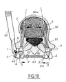
- - la Figure 10 est une vue en coupe transversale dans un plan coronal d'une vertèbre dorsale ou lombaire d'un dispositif d'ostéosynthèse équipé de vis selon l'invention.
- - Figure 1 is a partial longitudinal elevation view on an enlarged scale of a vertebral screw according to the invention;
- - Figures 2, 3 and 4 are views in longitudinal elevation of three alternative embodiments of the screw of Figure 1;
- - Figure 5 is a longitudinal elevational view on an enlarged scale of a screw according to the invention driven into the pedicle of a vertebra and crossed by a metal rod;
- - Figure 6 is an elevational view of two screws driven into two corresponding vertebrae and crossed by a common rod;
- - Figure 7 is a longitudinal elevational view of a test assembly of a screw according to the invention crossed by a rod locked in the body of the screw by two bolts;
- - Figure 8 illustrates a test setup for studying the flexural strength of a screw according to the invention;
- - Figures 9A and 9B are views in longitudinal elevation of a screw according to the invention in two different driving positions;
- - Figure 10 is a cross-sectional view in a coronal plane of a dorsal or lumbar vertebra of an osteosynthesis device equipped with screws according to the invention.
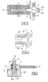
La vis vertèbrale selon l'invention, représentée à la Figure 1 à échelle très agrandie, est destinée à faire partie d'un dispositif d'ostéosynthèse, notamment du rachis lombaire et dorsal ou du sacrum.The vertebral screw according to the invention, shown in Figure 1 on a very enlarged scale, is intended to be part of an osteosynthesis device, in particular of the lumbar and dorsal spine or of the sacrum.
Cette vis 1, d'axe général X-X, comprend une tige filetée 2 dont l'extrémité, constituée par une partie cylindrique 5, est prolongée par un col profilé 3 et par un corps terminal 4.This
Le col 3 s'étend sur une longueur d entre la partie cylindrique 5 et le corps 4 et présente les parties suivantes, en coupe axiale et à partir de l'extrémité cylindrique 5, dont le diamètre est égal à celui du sommet des filets 2a de la tige 2 :
- a) une partie concave 6 dont le rayon r croît dans le direction opposée à celle de la tige filetée 2;
- b) une partie convexe 7 dont l'extrémité, de rayon maximum R, définit la base du corps cylindrique 4.
- a) a
concave part 6 whose radius r increases in the direction opposite to that of the threadedrod 2; - b) a convex part 7 whose end, of maximum radius R, defines the base of the
cylindrical body 4.
Ce dernier est percé de part en part, perpendiculairement à l'axe X-X, d'un alésage 8 destiné à recevoir une tige 9 (Figure 5).The latter is pierced right through, perpendicular to the axis X-X, with a bore 8 intended to receive a rod 9 (Figure 5).
Les parties concave 6 et convexe 7 présentent des points d'inflexion respectifs I1 et I2. Le profil de la partie concave 6 est déterminé pour permettre l'enfoncement de la vis 1 dans le pédicule d'une vertèbre lombaire ou dorsale jusqu'au milieu M environ du col sans détérioration de l'élément osseux, tandis que la partie convexe 7 et son rayon R sont dimensionnés de manière que le vissage ne soit pas gêné par les parties osseuses voisines (apophyses articulaires et apophyses transverses).The concave 6 and convex 7 parts have respective inflection points I1 and I2. The profile of the
Suivant un mode de réalisation avantageux, la partie concave 6 est dimensionnée pour que le diametre D1 au milieu M du col (6, 7) ne dépasse pas de plus de 60% environ le diamètre D2 des sommets des filets 2a.According to an advantageous embodiment, the
A titre d'exemple numérique indicatif, si D2=5mm, D1 ne doit pas dépasser 8 mm environ. En effet, une valeur de D1 sensiblement supérieure à la valeur précitée rendrait difficile l'introduction du col 3 dans l'élément osseux, et pourrait même détériorer celui-ci.As an indicative numerical example, if D2 = 5mm, D1 must not exceed approximately 8mm. Indeed, a value of D1 substantially greater than the aforementioned value would make it difficult to introduce the
La géométrie particulière du col 3, constituée par la combinaison des parties concave 6 et convexe 7 avec les caractéristiques mentionnées ci-dessus, présente par ailleurs l'avantage de permettre d'enfoncer la vis au maximum dans le pédicule, et donc de lui permettre de travailler en flexion dans des conditions satisfaisantes, et ce sans provoquer de détérioration de l'élément osseux.The particular geometry of the
La vis 1 est réalisée en un matériau biocompatible, par exemple un acier inoxydable austénitique.The
Les Figures 2 à 4 illustrent trois modes de réalisation possibles de la vis vertèbrale conforme à l'invention.Figures 2 to 4 illustrate three possible embodiments of the vertebral screw according to the invention.
Ces trois vis 12, 13, 14 comprennent chacune une tige filetée 15 et un col 16 identiques et diffèrent par leurs corps respectifs 17, 18, 19. Le corps 17 (Figure 2) est fermé et percé d'un alésage 21 pour le passage de la tige, ainsi que d'un trou de plus petit diamètre que l'alésage 21, s'étendant axialement à la vis et perpendiculairement à l'alésage 21 pour recevoir un boulon de serrage 22.These three
Le corps 18 de la vis 13 (Figure 3), à ouverture postérieure, se présente sous la forme de deux flancs 18a s'étendant de part et d'autre de l'axe de la vis 13 dans la direction opposée à la tige filetée 15. L'ouverture 18b délimitée par les flancs 18a est adaptée pour recevoir une pièce intermédiaire 23 de montage pour l'immobilisation de la vis 13 sur une tige à l'aide de deux boulons de serrage 24 (un seul étant visible à la Fig. 3).The
Le corps 19 de la vis 14 comporte une ouverture latérale 25 délimitée par deux flancs 19a de réception de la tige, dont le serrage est assuré par deux boulons 26 (dont un seul est visible).The
La Figure 5 montre le montage d'une vis pédiculaire 1 dans l'élément osseux 27, 28 du pédicule jusqu'au plan médian du col 3 défini par les points M. Le serrage de la tige 9 est assuré par deux boulons 29 engagés dans des trous du corps 4 ménagés parallèlement à l'axe X-X de part et d'autre de celui-ci, la vis 1 étant du type à corps fermé 4 selon la Figure 2.Figure 5 shows the mounting of a
Comme on l'expliquera ci-après plus en détail en référence à la Figure 7, le double blocage de la tige 9 par deux boulons 29 renforce considérablement la solidité de la fixation vis 1-tige 9 par rapport à la fixation à un seul boulon utilisée jusqu'à présent.As will be explained below in more detail with reference to FIG. 7, the double locking of the
La Figure 6 montre l'implantation de deux vis 1 reliées pour une tige 9 dans les pédicules 31 de deux vertèbres 32, 33 du rachis lombaire ou dorsal. Les vis 1 remplissent une fonction d'ancrage vertébral pour permettre l'expansion (également appelée "détraction") ou la compression des vertèbres entre elles ou par rapport au sacrum. Ces mouvements de "détraction" et de compression sont respectivement symbolisés par les flèches F et G. Les vis pédiculaires 1 doivent surtout pouvoir résister aux forces perpendiculaires à leur axe (F, G), alors que les vis à os doivent résister principalement aux forces axiales d'arrachement. Pour ces dernières, le filet de la vis est l'élément le plus important, tandis que pour les vis selon l'invention, le corps et le col sont les éléments essentiels. Il a été constaté qu'au-dessous d'un diamètre de 3,5 mm, le corps de la vis est insuffisant pour résister aux forces habituellement nécessaires à la correction des déviations rachidiennes. C'est pourquoi on utilise habituellement deux diamètres de vis vertébrale adulte :
- a) un diamètre extérieur de la partie filetée de 5 mm avec une longueur de 25 ou 40 mm, un filet de 0,75 mm et une âme de 3,5 mm;
- b) un diamètre extérieur de 6 mm pour la partie filetée, une longueur de 40 mm, un filet de 0,75 mm.
- a) an outside diameter of the threaded part of 5 mm with a length of 25 or 40 mm, a thread of 0.75 mm and a core of 3.5 mm;
- b) an outside diameter of 6 mm for the threaded part, a length of 40 mm, a thread of 0.75 mm.
Avant d'insérer une vis pédiculaire, il est nécessaire d'apprécier le diamètre du pédicule, et de s'assurer qu'il permet le passage de la vis, la largeur du pédicule variant en effet suivant les niveaux, les individus et la pathologie. Les tests mécaniques ont montré que la résistance aux forces perpendiculaires à l'axe de la vis est considérablement accrue, si celui-ci est enfoncé jusqu'à la moitié M du col (Figure 5), par exemple sur une distance de 2,5 mm à partir du début de la partie concave 6. Le vissage peut donc se faire jusqu'à ce niveau, la courbure particulière du col selon l'invention facilitant cette pénétration.Before inserting a pedicle screw, it is necessary to assess the diameter of the pedicle, and to make sure that it allows the passage of the screw, the width of the pedicle varying according to the levels, the individuals and the pathology . Mechanical tests have shown that the resistance to forces perpendicular to the axis of the screw is considerably increased, if it is pushed down to half M of the neck (Figure 5), for example over a distance of 2.5 mm from the start of the
La Figure 7 illustre un dispositif permettant de tester la résistance mécanique de la fixation entre la vis 1 et une tige moletée 9 lorsque celle-ci est assurée par deux vis 30 enfoncées dans le corps 4 de part et d'autre de l'axe X-X.Figure 7 illustrates a device for testing the mechanical strength of the attachment between the
Le corps 4 repose sur un bloc-support 34 percé d'un puits 35 de réception de la tige 9, le bloc-support 34 étant rigide afin d'éviter tout effet parasite de flexion. La résistance de la fixation à une force K exercée suivant l'axe de la tige 9 non perpendiculaire à l'axe X-X, est mesurée après vissage des vis 30 jusqu'à la rupture, la force K étant appliquée de façon progressive. Les résultats, comparés à ceux obtenus lorsque la fixation vis 1-tige 9 est assurée par une seule vis, ont montré que la fixation à deux vis 30 peut supporter un effort appliqué sur la tige 9 supérieur d'environ 35% à l'effort que peut supporter une fixation vis-tige réalisée par un seul boulon. A titre d'exemple indicatif, lorsque la fixation à un seul boulon résiste au maximum à un effort de 160 daN, la fixation à deux vis 30 peut résister à un effort de 210 daN.The
Cette supériorité de la fixation à deux boulons provient de l'accroissement de stabilité des tiges filetées sur les pointes de diamant 9a de la tige moletée 9. L'effort ci-dessus de 210 daN est le seuil de glissement de la tige 9 par rapport au corps 4 de la vis.This superiority of the two-bolt fixing comes from the increased stability of the threaded rods on the diamond points 9a of the
Le dispositif de la Figure 8 a pour fonction de permettre de tester la résistance de la vis 1 à la flexion en fonction de son dégré d'enfoncement dans un socle rigide 36 de support. Dans celui-ci est ménagé un canal 37 rempli de résine époxy 38 permettant de simuler un ancrage de la vis 1 dans un os. Un effort progressif E est appliqué dans l'axe Y-Y de l'alésage du corps 4 par l'intermédiaire d'une bille 39 et d'une pièce 41. Afin de compenser les longueurs de bras de levier différentes duex aux conditions expérimentales, la distance entre l'axe Y-Y et le plan P d'encastrement géométrique (Figures 9A et 9B) a été mesurée à chaque essai, afin de corriger les résultats pour pouvoir les comparer. (Le plan d'encastrement réel est légèrement distant du plan d'encastrement géométrique en raison du module élastique de l'os).The device of FIG. 8 has the function of making it possible to test the resistance of the
Les valeurs de l'effort E appliquées à chaque essai ont été relevées pour une déformation radiale de la vis 1 de 0,5mm mesurée à l'aide d'un comparateur 42. Dans la position de la Figure 9A, la vis 1 n'est enfoncée que jusqu'à sa partie cylindrique 5, donc à l'exclusion du col 3, tandis que dans la position de la Figure 9B, un enfoncement supplémentaire x a été réalisé jusqu'au milieu M du col 3. Les deux tableaux ci-dessous contiennent les résultats numériques de trois essais exécutés dans chaque cas, avec des vis de diamètre D2 = 5mm et D2 = 6mm.

Les résultats de ces essais montrent que dans le cas de l'encastrement de la Figure 9A, la résistance à la flexion de la vis vertébrale d'un diamètre de sa partie filetée D2 = 6 mm est d'environ 16% supérieure à celle de la vis de diamètre D2 = 5 mm. Ceci peut s'expliquer par la différence des sections des vis au droit du plan P d'encastrement.The results of these tests show that in the case of the embedding in FIG. 9A, the flexural strength of the vertebral screw with a diameter of its threaded part D2 = 6 mm is approximately 16% greater than that of the screw with diameter D2 = 5 mm. This can be explained by the difference in the cross-sections of the screws to the right of the embedding plane P.
Par contre, dans le cas de la Figure 9B, où la vis est enfoncée d'une distance x = 2 mm supérieure à son enfoncement sur la Figure 9A, jusqu'au plan milieu M de son col 3, les résultats ne font plus apparaitre de différence notables de comportement entre les deux vis (tableau 2).On the other hand, in the case of Figure 9B, where the screw is driven a distance x = 2 mm greater than its driving in Figure 9A, to the midplane M of its
Il est possible d'interpréter ces résultats par le fait que la géométrie des deux vis au niveau du plan d'encastrement P dans le cas de la Figure 9B est sensiblement la même. En fonction de ces résultats, on peut conclure que l'effort supporté par la vis avant déformation est augmenté de 235% pour la vis vertébrale de 5 mm de diamètre et de 200% pour la vis de 6 mm de diamètre, entre un enfoncement au niveau de la fin du filet 2a de la vis (Figure 9A) et un enfoncement supplémentaire de x = 2 mm (Figure 9B) dans les conditions d'essais précités.It is possible to interpret these results by the fact that the geometry of the two screws at the level of the embedding plane P in the case of FIG. 9B is substantially the same. Based on these results, it can be concluded that the force supported by the screw before deformation is increased by 235% for the vertebral screw of 5 mm in diameter and by 200% for the screw of 6 mm in diameter, between a recess at level of the end of the
On peut également déduire de ces résultats les indications suivantes :
- il est nécessaire d'utiliser le double boulonnage pour la fixation vis-tige afin d'en augmenter l'efficacité;
- il est important que les vis pédiculaires soient vissées au moins jusqu'à la moitié de leur col 3, afin d'obtenir une excellente résistance à la flexion;
- la différence de résistance à la flexion entre une vis de 5 mm de diamètre et une vis de 5 mm de diamètre diminue en fonction du degré de l'encastrement, jusqu'à devenir inexistante.The following indications can also be deduced from these results:
- it is necessary to use double bolting for screw-rod fixing in order to increase its efficiency;
- It is important that the pedicle screws are screwed at least up to half of their
- the difference in flexural strength between a 5 mm diameter screw and a 5 mm diameter screw decreases according to the degree of embedding, until it becomes non-existent.
La Figure 10 montre un exemple de mise en oeuvre de vis vertébrale 1 selon l'invention dans un montage d'ostéosynthèse du rachis lombaire ou dorsal. Les vis 1 sont implantées à travers les deux pédicules 31 sur le même corps vertèbral 32, convergent vers l'avant jusqu'à l'élément osseux 32a, sont traversées par deux tiges moletées 9 respectives et solidarisées entre elles en arrière par un dispositif de traction transversale à barrette filetée 43 traversant les corps 4. La barrette 43 est fixée en place au moyen d'écrous 44 serrés par un outil 45, en rapprochement en arrière des corps 4 et des deux vis 1.Figure 10 shows an example of implementation of
Ce dispositif de traction transversale (appelé couramment "D.T.T.") assure, de part la géométrie du montage, une excellente résistance à l'arrachement. Du fait du rapprochement en arrière des corps 4 des deux vis 1 par ce dispositif "D.T.T.", les forces exercées par celui-ci étant symbolisées par les flèches T1, les parties filetées antérieures 2 des vis 1 tendent à venir au contact, sous l'effet des forces correspondantes T2 développées à ce niveau dans la vertèbre, avec la corticale latérale 32a du corps vertébral 32, plus résistante que l'os spongieux, ce qui améliore encore la stabilité du montage.This transverse traction device (commonly called "DTT") ensures, due to the geometry of the assembly, excellent resistance to tearing. Due to the rearward movement of the
On remarque que les cols 3 et le corps 4 des deux vis 1 peuvent être mis en place jusqu'au degré d'enfoncement désiré dans les pédicules 31, sans que leur pénétration soit gêné par les apophyses 46.It is noted that the
Bien entendu, le montage de la Figure 10 n'est donnée qu'à titre d'exemple non limitatif parmi les différentes possibilités de mise en oeuvre des vis vertébrales selon l'invention dans des dispositifs d'ostéosynthèse.Of course, the assembly of Figure 10 is given only by way of nonlimiting example among the different possibilities of implementation of the vertebral screws according to the invention in osteosynthesis devices.
Claims (4)
Applications Claiming Priority (2)
| Application Number | Priority Date | Filing Date | Title |
|---|---|---|---|
| FR8703485A FR2612071A1 (en) | 1987-03-13 | 1987-03-13 | VERTEBRAL SCREW FOR OSTEOSYNTHESIS DEVICE, ESPECIALLY LUMBAR AND DORSAL |
| FR8703485 | 1987-03-13 |
Publications (1)
| Publication Number | Publication Date |
|---|---|
| EP0283373A1 true EP0283373A1 (en) | 1988-09-21 |
Family
ID=9348954
Family Applications (1)
| Application Number | Title | Priority Date | Filing Date |
|---|---|---|---|
| EP88400519A Withdrawn EP0283373A1 (en) | 1987-03-13 | 1988-03-04 | Vertebral screw for an osteosynthesis device, especially for the lumbar and dorsal spine |
Country Status (4)
| Country | Link |
|---|---|
| EP (1) | EP0283373A1 (en) |
| JP (1) | JPS6476847A (en) |
| AU (1) | AU599464B2 (en) |
| FR (1) | FR2612071A1 (en) |
Cited By (20)
| Publication number | Priority date | Publication date | Assignee | Title |
|---|---|---|---|---|
| FR2642643A1 (en) * | 1989-02-09 | 1990-08-10 | Vignaud Jean Louis | SPINAL INSTRUMENTATION FOR UNIVERSAL PEDICULAR FASTENING BY DIAPASON SCREW WITH MICROMETRIC ADJUSTMENT |
| FR2642642A1 (en) * | 1989-02-03 | 1990-08-10 | Cotrel Yves | Spinal posterior osteosynthesis implant |
| EP0383992A2 (en) * | 1989-02-08 | 1990-08-29 | Acromed Corporation | Transverse connector for spinal column corrective devices |
| EP0384001A1 (en) * | 1989-02-08 | 1990-08-29 | Acromed Corporation | Connector for attaching a corrective device to vertebrae |
| EP0392927A2 (en) * | 1989-04-13 | 1990-10-17 | Societe De Fabrication De Materiel Orthopedique | Vertebral implant for osteosynthesis device |
| US5122131A (en) * | 1991-03-14 | 1992-06-16 | Tsou Paul M | Orthopaedic device for mechanical coupling to a surgical rod |
| EP0534053A2 (en) * | 1991-09-23 | 1993-03-31 | Chih-I Lin | Vertebral locking and retrieving system |
| FR2728158A1 (en) * | 1994-12-14 | 1996-06-21 | Elberg Jean Francois | Spinal column prosthesis |
| FR2735351A1 (en) * | 1995-06-13 | 1996-12-20 | Sofamor | IMPLANT FOR THE SURGICAL TREATMENT OF A VERTEBRAL ISTHUMIC FRACTURE |
| FR2747910A1 (en) * | 1996-04-30 | 1997-10-31 | Harms Jurgen | ANCHORING ELEMENT FOR ANCHORING INTO A BONE |
| FR2802796A1 (en) * | 1999-12-24 | 2001-06-29 | Materiel Orthopedique En Abreg | Bolt for connecting vertebra to longitudinal member, e.g. spine |
| WO2001047425A1 (en) * | 1999-12-24 | 2001-07-05 | Societe De Fabrication De Materiel Orthopedique (Sofamor) | Pedicle screws with inclined channels to hold support rods |
| US6802844B2 (en) | 2001-03-26 | 2004-10-12 | Nuvasive, Inc | Spinal alignment apparatus and methods |
| US7833251B1 (en) | 2004-01-06 | 2010-11-16 | Nuvasive, Inc. | System and method for performing spinal fixation |
| US7854751B2 (en) | 2003-12-16 | 2010-12-21 | Dupuy Spine, Inc. | Percutaneous access devices and bone anchor assemblies |
| US9060813B1 (en) | 2008-02-29 | 2015-06-23 | Nuvasive, Inc. | Surgical fixation system and related methods |
| US9198696B1 (en) | 2010-05-27 | 2015-12-01 | Nuvasive, Inc. | Cross-connector and related methods |
| US9247964B1 (en) | 2011-03-01 | 2016-02-02 | Nuasive, Inc. | Spinal Cross-connector |
| US9387013B1 (en) | 2011-03-01 | 2016-07-12 | Nuvasive, Inc. | Posterior cervical fixation system |
| US11419642B2 (en) | 2003-12-16 | 2022-08-23 | Medos International Sarl | Percutaneous access devices and bone anchor assemblies |
Families Citing this family (6)
| Publication number | Priority date | Publication date | Assignee | Title |
|---|---|---|---|---|
| WO1990002526A1 (en) * | 1988-09-09 | 1990-03-22 | Australian Defence Industries Pty. Limited | Screw |
| JPH0595508U (en) * | 1991-03-12 | 1993-12-27 | 高橋 賢三 | Intramedullary nail for fixation of distal radius fracture |
| JPH07163580A (en) * | 1993-12-15 | 1995-06-27 | Mizuho Ika Kogyo Kk | Forward correcting device for scoliosis |
| JPH08336548A (en) * | 1995-06-13 | 1996-12-24 | Mizuho Ika Kogyo Kk | Centrum screw of spine correcting device |
| CN100376219C (en) * | 1998-07-06 | 2008-03-26 | 株式会社率高 | Spine fixing apparatus |
| CN108498155B (en) * | 2018-04-26 | 2023-06-20 | 重庆医科大学附属永川医院 | Self-locking anti-rotation pedicle screw and use method thereof |
Citations (7)
| Publication number | Priority date | Publication date | Assignee | Title |
|---|---|---|---|---|
| FR1000475A (en) * | 1949-11-30 | 1952-02-12 | Screws for fixing bicycle mudguards | |
| AT293458B (en) * | 1963-05-24 | 1971-10-11 | Boehler & Co Ag Geb | Bone nails and bone wires |
| US3670619A (en) * | 1969-10-28 | 1972-06-20 | William M Coats | Horseshoe fastener |
| DE2649042B1 (en) * | 1976-10-28 | 1978-01-05 | Ulrich Max Bernhard | Corrective implant for anterior derotation spondylodesis and device for adjusting the corrective implant |
| FR2369825A1 (en) * | 1976-10-28 | 1978-06-02 | Inst Med Instrumen | Appts. for scoliosis correction and spondylodesis - has hip and chest belts together with flexible cords attached to vertebra and tension distributor |
| US4111580A (en) * | 1976-12-30 | 1978-09-05 | The Boeing Company | Continuously curved fastener head and countersink have interference fit |
| FR2506605A1 (en) * | 1981-05-29 | 1982-12-03 | Ulrich Max | DETRACTION APPARATUS, PARTICULARLY FOR CORRECTING KYPHOSES |
Family Cites Families (1)
| Publication number | Priority date | Publication date | Assignee | Title |
|---|---|---|---|---|
| GB1551706A (en) * | 1975-04-28 | 1979-08-30 | Downs Surgical Ltd | Surgical implant |
-
1987
- 1987-03-13 FR FR8703485A patent/FR2612071A1/en not_active Withdrawn
-
1988
- 1988-03-04 EP EP88400519A patent/EP0283373A1/en not_active Withdrawn
- 1988-03-08 AU AU12800/88A patent/AU599464B2/en not_active Withdrawn - After Issue
- 1988-03-14 JP JP63060177A patent/JPS6476847A/en active Pending
Patent Citations (7)
| Publication number | Priority date | Publication date | Assignee | Title |
|---|---|---|---|---|
| FR1000475A (en) * | 1949-11-30 | 1952-02-12 | Screws for fixing bicycle mudguards | |
| AT293458B (en) * | 1963-05-24 | 1971-10-11 | Boehler & Co Ag Geb | Bone nails and bone wires |
| US3670619A (en) * | 1969-10-28 | 1972-06-20 | William M Coats | Horseshoe fastener |
| DE2649042B1 (en) * | 1976-10-28 | 1978-01-05 | Ulrich Max Bernhard | Corrective implant for anterior derotation spondylodesis and device for adjusting the corrective implant |
| FR2369825A1 (en) * | 1976-10-28 | 1978-06-02 | Inst Med Instrumen | Appts. for scoliosis correction and spondylodesis - has hip and chest belts together with flexible cords attached to vertebra and tension distributor |
| US4111580A (en) * | 1976-12-30 | 1978-09-05 | The Boeing Company | Continuously curved fastener head and countersink have interference fit |
| FR2506605A1 (en) * | 1981-05-29 | 1982-12-03 | Ulrich Max | DETRACTION APPARATUS, PARTICULARLY FOR CORRECTING KYPHOSES |
Cited By (41)
| Publication number | Priority date | Publication date | Assignee | Title |
|---|---|---|---|---|
| FR2642642A1 (en) * | 1989-02-03 | 1990-08-10 | Cotrel Yves | Spinal posterior osteosynthesis implant |
| EP0383992A3 (en) * | 1989-02-08 | 1990-11-22 | Acromed Corporation | Transverse connector for spinal column corrective devices |
| US5084049A (en) * | 1989-02-08 | 1992-01-28 | Acromed Corporation | Transverse connector for spinal column corrective devices |
| EP0383992A2 (en) * | 1989-02-08 | 1990-08-29 | Acromed Corporation | Transverse connector for spinal column corrective devices |
| EP0384001A1 (en) * | 1989-02-08 | 1990-08-29 | Acromed Corporation | Connector for attaching a corrective device to vertebrae |
| US5129388A (en) * | 1989-02-09 | 1992-07-14 | Vignaud Jean Louis | Device for supporting the spinal column |
| WO1990009156A1 (en) * | 1989-02-09 | 1990-08-23 | Vignaud Jean Louis | A supporting device for the spinal column |
| FR2642643A1 (en) * | 1989-02-09 | 1990-08-10 | Vignaud Jean Louis | SPINAL INSTRUMENTATION FOR UNIVERSAL PEDICULAR FASTENING BY DIAPASON SCREW WITH MICROMETRIC ADJUSTMENT |
| US5067955A (en) * | 1989-04-13 | 1991-11-26 | Societe De Fabrication De Material Orthopedique | Vertebral implant for osteosynthesis device |
| FR2645732A1 (en) * | 1989-04-13 | 1990-10-19 | Cotrel Yves | VERTEBRAL IMPLANT FOR OSTEOSYNTHESIS DEVICE |
| EP0392927A3 (en) * | 1989-04-13 | 1991-08-07 | Societe De Fabrication De Materiel Orthopedique | Vertebral implant for osteosynthesis device |
| EP0392927A2 (en) * | 1989-04-13 | 1990-10-17 | Societe De Fabrication De Materiel Orthopedique | Vertebral implant for osteosynthesis device |
| US5122131A (en) * | 1991-03-14 | 1992-06-16 | Tsou Paul M | Orthopaedic device for mechanical coupling to a surgical rod |
| EP0534053A2 (en) * | 1991-09-23 | 1993-03-31 | Chih-I Lin | Vertebral locking and retrieving system |
| EP0534053A3 (en) * | 1991-09-23 | 1993-07-21 | Chih-I Lin | Vertebral locking and retrieving system |
| FR2728158A1 (en) * | 1994-12-14 | 1996-06-21 | Elberg Jean Francois | Spinal column prosthesis |
| FR2735351A1 (en) * | 1995-06-13 | 1996-12-20 | Sofamor | IMPLANT FOR THE SURGICAL TREATMENT OF A VERTEBRAL ISTHUMIC FRACTURE |
| WO1996041582A1 (en) * | 1995-06-13 | 1996-12-27 | Societe De Fabrication De Materiel Orthopedique En Abrege - Sofamor | Implant for surgically treating a vertebral isthmic fracture |
| FR2747910A1 (en) * | 1996-04-30 | 1997-10-31 | Harms Jurgen | ANCHORING ELEMENT FOR ANCHORING INTO A BONE |
| WO2001047425A1 (en) * | 1999-12-24 | 2001-07-05 | Societe De Fabrication De Materiel Orthopedique (Sofamor) | Pedicle screws with inclined channels to hold support rods |
| FR2802796A1 (en) * | 1999-12-24 | 2001-06-29 | Materiel Orthopedique En Abreg | Bolt for connecting vertebra to longitudinal member, e.g. spine |
| US7303562B2 (en) | 1999-12-24 | 2007-12-04 | Sdgi Holdings, Inc. | Pedicle screws with inclined channels to hold support rods |
| US6802844B2 (en) | 2001-03-26 | 2004-10-12 | Nuvasive, Inc | Spinal alignment apparatus and methods |
| US10299839B2 (en) | 2003-12-16 | 2019-05-28 | Medos International Sárl | Percutaneous access devices and bone anchor assemblies |
| US7854751B2 (en) | 2003-12-16 | 2010-12-21 | Dupuy Spine, Inc. | Percutaneous access devices and bone anchor assemblies |
| US8518082B2 (en) | 2003-12-16 | 2013-08-27 | Depuy Spine, Sarl | Percutaneous access devices and bone anchor assemblies |
| US8617210B2 (en) | 2003-12-16 | 2013-12-31 | Depuy Spine, Sarl | Percutaneous access devices and bone anchor assemblies |
| US11419642B2 (en) | 2003-12-16 | 2022-08-23 | Medos International Sarl | Percutaneous access devices and bone anchor assemblies |
| US9439699B2 (en) | 2003-12-16 | 2016-09-13 | Medos International Sarl | Percutaneous access devices and bone anchor assemblies |
| US7833251B1 (en) | 2004-01-06 | 2010-11-16 | Nuvasive, Inc. | System and method for performing spinal fixation |
| US9060813B1 (en) | 2008-02-29 | 2015-06-23 | Nuvasive, Inc. | Surgical fixation system and related methods |
| US9198696B1 (en) | 2010-05-27 | 2015-12-01 | Nuvasive, Inc. | Cross-connector and related methods |
| US9770269B1 (en) | 2011-03-01 | 2017-09-26 | Nuvasive, Inc. | Spinal Cross-connector |
| US9956009B1 (en) | 2011-03-01 | 2018-05-01 | Nuvasive, Inc. | Posterior cervical fixation system |
| US10136925B2 (en) | 2011-03-01 | 2018-11-27 | Nuvasive, Inc. | Spinal cross-connector |
| US9387013B1 (en) | 2011-03-01 | 2016-07-12 | Nuvasive, Inc. | Posterior cervical fixation system |
| US10368918B2 (en) | 2011-03-01 | 2019-08-06 | Nuvasive, Inc. | Posterior cervical fixation system |
| US10779865B2 (en) | 2011-03-01 | 2020-09-22 | Nuvasive, Inc. | Spinal cross connector |
| US11123110B2 (en) | 2011-03-01 | 2021-09-21 | Nuvasive, Inc. | Posterior cervical fixation system |
| US9247964B1 (en) | 2011-03-01 | 2016-02-02 | Nuasive, Inc. | Spinal Cross-connector |
| US11478282B2 (en) | 2011-03-01 | 2022-10-25 | Nuvasive, Inc. | Spinal cross connector |
Also Published As
| Publication number | Publication date |
|---|---|
| JPS6476847A (en) | 1989-03-22 |
| AU599464B2 (en) | 1990-07-19 |
| FR2612071A1 (en) | 1988-09-16 |
| AU1280088A (en) | 1988-09-15 |
Similar Documents
| Publication | Publication Date | Title |
|---|---|---|
| EP0283373A1 (en) | Vertebral screw for an osteosynthesis device, especially for the lumbar and dorsal spine | |
| EP0947175B1 (en) | Spinal osteosynthesis device adaptable to the position of a pedicle screw | |
| CA2133766C (en) | Spinal osteosynthesis device | |
| EP1075224B1 (en) | Backbone osteosynthesis system with clamping means in particular for anterior fixing | |
| WO2000021447A1 (en) | Spinal osteosynthesis system with improved stability | |
| EP3376982B1 (en) | Double-threaded bone screw | |
| FR2965471A1 (en) | Intramedullary fixing assembly for mechanically connecting head and body of femur of patient, has blocking unit cooperating with groove so as to block fastening screw in rotation in assembled position | |
| EP2996590B1 (en) | Revision assembly for an item of vertebral osteosynthesis equipment | |
| EP4132391B1 (en) | Cortically stabilized bone anchoring implant | |
| EP1361827B1 (en) | Fixing screw | |
| EP3116426A1 (en) | Osteosynthesis system comprising means for straightening a bone anchoring element relative to a screw head and anchoring screw implemented in such a system | |
| EP1967150A1 (en) | Vertebral anchoring device using an intrapedicular nail | |
| FR3027209A1 (en) | MULTI-AXIAL VERTEBRAL ANCHORING DEVICE FOR RESTRICTING A VERTEBRA | |
| WO2013175099A1 (en) | Self-compressing osteosynthesis screw | |
| FR3066380A1 (en) | POLYAXIAL BONE SCREW FOR OSTEOSYNTHESIS DEVICE, AND OSTEOSYNTHESIS DEVICE COMPRISING SAME. | |
| FR3106968A1 (en) | System for connecting at least two portions of bone | |
| FR3085113A1 (en) | ASSISTANCE DEVICE FOR THE RECONSTRUCTION OF A VERTEBRA | |
| FR2802797A1 (en) | Bolt for connecting vertebra to longitudinal member, e.g. spine | |
| FR2671715A1 (en) | Artificial ligament blocking device which can be used in surgery | |
| WO2007010410A1 (en) | Osteosynthetic implant | |
| FR2833152A1 (en) | COMPRESSIVE BONE ANCHORING DEVICE | |
| FR2726170A1 (en) | Osteosynthesis implant for fastening vertebrae |
Legal Events
| Date | Code | Title | Description |
|---|---|---|---|
| PUAI | Public reference made under article 153(3) epc to a published international application that has entered the european phase |
Free format text: ORIGINAL CODE: 0009012 |
|
| AK | Designated contracting states |
Kind code of ref document: A1 Designated state(s): AT BE CH DE ES GB GR IT LI LU NL SE |
|
| 17P | Request for examination filed |
Effective date: 19890311 |
|
| 17Q | First examination report despatched |
Effective date: 19900906 |
|
| STAA | Information on the status of an ep patent application or granted ep patent |
Free format text: STATUS: THE APPLICATION HAS BEEN WITHDRAWN |
|
| 18W | Application withdrawn |
Withdrawal date: 19901009 |