EP0281518A2 - Geodetic instrument - Google Patents
Geodetic instrument Download PDFInfo
- Publication number
- EP0281518A2 EP0281518A2 EP88810109A EP88810109A EP0281518A2 EP 0281518 A2 EP0281518 A2 EP 0281518A2 EP 88810109 A EP88810109 A EP 88810109A EP 88810109 A EP88810109 A EP 88810109A EP 0281518 A2 EP0281518 A2 EP 0281518A2
- Authority
- EP
- European Patent Office
- Prior art keywords
- reference mark
- optical
- instrument
- camera
- image
- Prior art date
- Legal status (The legal status is an assumption and is not a legal conclusion. Google has not performed a legal analysis and makes no representation as to the accuracy of the status listed.)
- Granted
Links
Images

Classifications
-
- G—PHYSICS
- G01—MEASURING; TESTING
- G01C—MEASURING DISTANCES, LEVELS OR BEARINGS; SURVEYING; NAVIGATION; GYROSCOPIC INSTRUMENTS; PHOTOGRAMMETRY OR VIDEOGRAMMETRY
- G01C15/00—Surveying instruments or accessories not provided for in groups G01C1/00 - G01C13/00
-
- G—PHYSICS
- G01—MEASURING; TESTING
- G01C—MEASURING DISTANCES, LEVELS OR BEARINGS; SURVEYING; NAVIGATION; GYROSCOPIC INSTRUMENTS; PHOTOGRAMMETRY OR VIDEOGRAMMETRY
- G01C1/00—Measuring angles
- G01C1/02—Theodolites
-
- G—PHYSICS
- G01—MEASURING; TESTING
- G01C—MEASURING DISTANCES, LEVELS OR BEARINGS; SURVEYING; NAVIGATION; GYROSCOPIC INSTRUMENTS; PHOTOGRAMMETRY OR VIDEOGRAMMETRY
- G01C1/00—Measuring angles
- G01C1/02—Theodolites
- G01C1/04—Theodolites combined with cameras
Definitions
- the present invention relates to a measuring instrument with a component for optically imaging a target and with a camera for electronically capturing the image generated in the optical instrument part.
- a telescopic sight serves as an optical component of such an instrument.
- a camera is assigned to the telescope, the image of the crosshair and the target, the target figure or the target mark captured by the telescope being shown on a screen.
- the riflescope can be adjusted in such a way that the middle part of the image of the target and the middle part of the crosshairs overlap.
- the measured values can only be obtained by the operator adjusting the optical part thereof. In some applications of surveying instruments, however, it is required that the measured values are recorded automatically.
- the object of the present invention is to provide a measuring instrument which enables measurements to be carried out automatically.
- the present measuring instrument has an optical component 1 and a camera 2.
- the optical instrument part 1 is used to image a target or a target mark (not shown), which are located in the target area, for example in a terrain to be measured, inside a building or the like, and which mark the respective location of the object to be measured.
- a measurement mark known per se can be used as such a mark.
- the camera 2 has an optical entry part 23, in which there is an array of optoelectric elements. These are used to convert optical images into electrical signals. Such cameras are also already known.
- the coupling between the exit part of the optical instrument part 1 and the optical entry part 23 of the camera 2 takes place with the aid of an optical deflection device 3, which is connected between these two instrument parts 1 and 2.
- This deflection device 3 contains, in addition to other parts, e.g. an imaging optics 8, also a prism 4, which effects the required deflection of the optical beams to the camera 2.
- the optical part 1 has a lens 5, which is located in the beginning of a housing 6.
- an eyepiece 7 In the opposite end part of this housing 6 there is an eyepiece 7 to which the deflection device 3 is assigned.
- an aperture 10 which bears a reference mark (20, FIG. 2 and the following). This means that both the image of the target and the reference mark are visible at the same time.
- the eyepiece 7 is arranged with respect to this plane in such a way that this plane is located in the front focal plane of the eyepiece 7. The image of the target and the image of the reference mark can thus be viewed simultaneously through the eyepiece 7 to be watched.
- the tilt axis 12 consists of two shaft halves 121, of which only the shaft half 121 mounted in the rear support side 11 is indicated in FIG. 1.
- the ends of the shaft halves 121 facing away from the bearing points are fastened to the side surfaces of a sleeve 31, which thus forms a unit rotatable about the tilt axis with these shaft halves 121.
- the camera 2 is located on a support plate 13 which is fastened on the top of the sleeve 31 with the aid of screws 14.
- the inner diameter of said sleeve 31 is larger than the outer diameter of the middle part of the telescope housing 6.
- This middle part of the housing 6, which is cylindrical, is provided with a holding plate 9 which is perpendicular to the longitudinal axis of the housing 6. Bores are made in the corners of this holding plate 9, through which fastening screws 32 for the telescope 1 pass. These screws 32 are screwed into threaded holes which are made in the front of the sleeve 31.
- the outer edge 15 of the panel 10 is practically circular because the panel 10 is to be arranged in the housing 6. Edge 15 can, however, also be regarded as the outer limit of the image field of telescope 1.
- an opening 16 is made, which has an edge 17.
- the target line of the telescope 1 passes approximately through the center of this aperture 16.
- the already mentioned reference mark 20 is located in the aperture 16.
- the reference mark 20 has the shape of a square frame, which is located within the aperture opening 16. This means that the outer edge of the reference mark 20 is at a distance from the inner edge 17 of the aperture opening 16.
- the section 18 of the diaphragm 10 lying between the outer edge of the reference mark 20 and the edge 17 of the diaphragm opening 16 is as transparent to the radiation as the area of the diaphragm 10 located within the reference mark 20
- Reference mark 20 is designed in such a way that the radiation incident on the aperture 10 is at least partially prevented from passing through the aperture 10.
- the camera 2 captures the central area of the diaphragm 10.
- the area of the diaphragm 10 captured by the camera 2 is larger than the area of the diaphragm opening 16. This means that the camera 2 not only the Surface of the diaphragm opening 16 but also that area 19 of the portion 22 of the diaphragm 10 which is opaque to the radiation and which directly adjoins the diaphragm opening 16. In this way, the dimensions of the camera field of view are expanded not only in the horizontal but also in the vertical direction.
- the outer limit of the field of view of the camera 2 is designated by 21.
- FIG. 3 shows a diaphragm 10 in which the edge 17 of the diaphragm opening 16 is circular and in which the reference mark 20 is in the form of a ring which is at a distance 18 from the edge 17 of the diaphragm opening 16. In the example shown, this distance 18 is the same size in any direction of the diaphragm 10.
- FIG. 4 shows a further embodiment of the reference mark 20, in which the aperture opening 16 and the reference mark 20 are hexagonal.
- the width of the permeable region 18 between the reference mark 20 and the diaphragm edge 17 variable or unequal in size along the reference mark 20. This can even go so far that the reference mark 20 is designed as an extension of the aperture edge 17.
- the reference mark 20 can be designed as one or more, in the present case as two cutouts 201 and 202 from a self-contained figure.
- a rectangle represents the closed figure for the reference mark 20 according to FIG. 5.
- this is a circle.
- the respective section 201 and 202 of the reference mark 20 according to FIG. 5 is approximately L-shaped, wherein the legs 25 and 26 of the respective L-shaped section 201 and 202 of the reference mark 20 can be of the same or different lengths. In the example shown, the legs 25 and 26 have different lengths, the longer legs 25 running horizontally.
- the sections 201 and 202 of the reference mark 20 are arranged in opposite corners of the square diaphragm opening 16, the width of the permeable area 18 of the diaphragm 10 between the sections 201 and 202 of the reference mark 20 and the edge 17 of the diaphragm opening 16 in the two mark sections 201 and 202 the same and at the same time is unchangeable.
- the reference mark 20 consists of two arcuate sections 201 and 202, which are arranged diametrically opposite one another in a circular aperture opening 16.
- the distance 18 between the mark sections 201 and 202 and the edge 17 of the aperture opening 16 is the same and constant.
- FIG. 7 shows an aperture 10 which is very similar to the aperture according to FIG. 2.
- the aperture 10 according to FIG. 7 has alignment marks 30. These alignment marks 30 are used to adjust the aperture 10 within the telescope 1, as is generally known. Since these alignment marks 30 are not directly involved in obtaining measurement results, they are located outside the outer limit 21 of the field of view of the camera 2 in the area 22 of the diaphragm 10 that is otherwise impenetrable to radiation.
- the alignment marks 30 are diamond-shaped. Such an alignment mark 30 is located symmetrically to the respective side of the frame 20, the longer diagonal of the diamond 30 being perpendicular to the respective side of the square-shaped reference mark 20.
- the optical entry part of the camera 2 which over the Deflection device 4 is coupled to the telescope 1, there is a field of elements which are sensitive to the radiation impinging thereon, for example light. These sensors convert the radiation into electrical signals.
- the sensitive elements are arranged within the field so that they form rows and columns.
- the shape and size of the sensor field is indicated by the outer boundary 21 of the field of view of the camera 2.
- the boundary line 21 of the field of view of the camera 2 For the function of the present instrument, it is irrelevant whether the area of the sensor field is actually as large as is indicated by the boundary line 21, or whether the boundary 21 of the sensor field results from a projection of this field into the plane of the diaphragm 10, for example by the deflection device 4.
- a particular elementary area of the surface of the diaphragm 10, which is delimited by the boundary line 21 of the image field of the camera 2 is assigned to the respective element of the sensor field 21 that is sensitive to the radiation.
- the image field of the camera 2 thus also includes the edge part 19 of the diaphragm 10.
- the course of the edge 17 of the aperture 16 and / or the shape of the reference mark 20 can be determined electrically, specifically as a contrast to the uncovered elements mentar surfaces of the aperture 10.
- a first of these surfaces is located in the area of the aperture opening 16 delimited by the reference mark 20, while a second such surface 18 lies between the outer edge of the reference mark 20 and the edge 17 of the aperture opening 16.
- the optical part 1 of the present instrument can first be aligned in such a way that the image of the desired or sought-after target figure falls in that area of the aperture 16 that is located within the reference mark 20.
- the image of the target figure like the reference mark 20, etc., is distinguished by adjacent contrasts between light and dark.
- the sensor in the camera 2 assigned to the respective elementary surface of the aperture 16 therefore delivers an electrical signal or not, depending on whether it is in a light or dark area of the image of the target figure. In this way, not only the shape of the image of the target figure but also its position within the aperture 16 can be detected electrically.
- the circuits connected to the camera 2 can therefore also provide basic information as to whether the image of one or a specific target figure is in the aperture 16 or not.
- the reference mark 20 can have the shape of a quadrangle, a polygon, a circle or at least a section thereof or a part thereof. Circuits are already known which can calculate the center of gravity of the respective curve from the electrical signals reproduced in such curves. Such a circuit can be part of the circuit arrangement connected to the output of the camera 2. The center of gravity SR of the reference mark 20 calculated in this way forms one of the points of the target line of the telescope 1.
- the circuit mentioned can also calculate the center of gravity SM of the image of the target in the same way.
- the route A which connects these two points SR and SM, has one te length and a certain direction.
- the electrical circuit arrangement connected to the camera 2 is also designed such that it is able to determine the length and the direction of the distance A mentioned between the two focal points SR and SM. With the information relating to this route A, the rough information already mentioned and read from the component circles of the instrument is corrected, so that precise information about the location of the target can be made.
- the reference mark can be designed differently.
- only the edge 17 or the edge region 19 of the aperture opening 16 can serve as the reference mark, so that no special reference mark is required in the aperture opening.
- a mark 20 or 201, 202 or the like designed as described can be arranged in the image field of the optical instrument part without it being surrounded by an aperture.
- the present invention relates to all possible embodiments of the subject matter disclosed in these documents, which are within the scope of the applicable protection request. It should also be pointed out that all features disclosed in the present documents are to be regarded as essential to the invention.
Abstract
Description
Die vorliegende Erfindung betrifft ein Vermessungsinstrument mit einem Bestandteil zur optischen Abbildung eines Zieles und mit einer Kamera zum elektronischen Erfassen des im optischen Instrumententeil erzeugten Bildes.The present invention relates to a measuring instrument with a component for optically imaging a target and with a camera for electronically capturing the image generated in the optical instrument part.
Vermessungsinstrumente dieser Gattung sind bereits bekannt. Als optischer Bestandteil eines solchen Instrumentes dient ein Zielfernrohr. Im Zielfernrohr befindet sich ein Strichkreuz. Dem Fernrohr ist eine Kamera zugeordnet, wobei das von dieser erfasste Bild des Strichkreuzes und des Zieles, der Zielfigur bzw. der Zielmarke an einem Bildschirm gezeigt werden. Mit Hilfe von Bedienelementen kann man das Zielfernrohr derart einstellen, dass sich die mittlere Partie des Bildes des Zieles und die mittlere Partie des Strichkreuzes überdecken.Surveying instruments of this type are already known. A telescopic sight serves as an optical component of such an instrument. There is a crosshair in the scope. A camera is assigned to the telescope, the image of the crosshair and the target, the target figure or the target mark captured by the telescope being shown on a screen. With the help of operating elements, the riflescope can be adjusted in such a way that the middle part of the image of the target and the middle part of the crosshairs overlap.
Bei einem solchen Instrument können die Messwerte nur durch Einstellen des optischen Teiles desselben durch den Bediener gewonnen werden. In manchen Anwendungsfällen von Vermessungsinstrumenten wird jedoch verlangt, dass die Messwerte automatisch erfasst werden.With such an instrument, the measured values can only be obtained by the operator adjusting the optical part thereof. In some applications of surveying instruments, however, it is required that the measured values are recorded automatically.
Die Aufgabe der vorliegenden Erfindung ist, ein Vermessungsinstrument anzugeben, das eine automatische Durchführung von Messungen ermöglicht.The object of the present invention is to provide a measuring instrument which enables measurements to be carried out automatically.
Diese Aufgabe wird beim Vermessungsinstrument der eingangs genannten Gattung erfindungsgemäss so gelöst, wie dies im kennzeichnenden Teil des Anspruchs 1 definiert ist.This object is achieved according to the invention in the surveying instrument of the type mentioned at the outset, as defined in the characterizing part of claim 1.
Im Nachstehenden werden Ausführungsbeispiele der vorliegenden Erfindung anhand der beiliegenden Zeichnungen näher erläutert. Es zeigt:
- Fig. 1 eine Seitenansicht des vorliegenden Instrumentes,
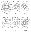
- Fig. 2 eine Frontansicht einer sich im vorliegenden Instrument befindlichen Blende,
- Fig. 3 bis 6 weitere Ausführungen der Blende gemäss Fig. 2 und
- Fig. 7 eine Blende, die mit Justiermarken versehen ist.
- 1 is a side view of the present instrument,
- 2 shows a front view of an aperture located in the present instrument,
- 3 to 6 further versions of the panel according to FIGS. 2 and
- Fig. 7 is an aperture which is provided with alignment marks.
Das vorliegende Vermessungsinstrument weist einen optischen Bestandteil 1 sowie eine Kamera 2 auf. Der optische Instrumententeil 1 dient zur Abbildung eines Zieles bzw. einer Zielmarke (nicht dargestellt), welche sich im Zielraum, z.B. in einem zu vermessenden Gelände, im Inneren eines Gebäudes oder dgl., befinden und welche die jeweilige Stelle des zu vermessenden Objektes markieren. Als eine solche Marke kann beispielsweise eine an sich bekannte Messmarke verwendet werden.The present measuring instrument has an optical component 1 and a
Die Kamera 2 weist eine optische Eintrittspartie 23 auf, in der sich ein Feld aus optoelektrischen Elementen befindet. Diese dienen zum Umwandeln optischer Bilder in elektrische Signale. Solche Kameras sind ebenfalls bereits bekannt. Die Kopellung zwischen der Austrittspartie des optischen Instrumententeiles 1 und der optischen Eintrittspartie 23 der Kamera 2 erfolgt mit Hilfe einer optischen Umlenkvorrichtung 3, welche zwischen diesen zwei Instrumententeilen 1 und 2 geschaltet ist. Diese Umlenkvorrichtung 3 enthält neben weiteren Teilen, wie z.B. einer Abbildungsoptik 8, auch ein Prisma 4, welches die erforderliche Umlenkung der optischen Strahlen zur Kamera 2 bewirkt.The
Der optische Teil 1 weist ein Objektiv 5 auf, das sich in der Anfangspartie eines Gehäuses 6 befindet. In der gegenüberliegenden Endpartie dieses Gehäuses 6 befindet sich ein Okular 7, dem die Umlenkvorrichtung 3 zugeordnet ist. In der Ebene, in welcher das vom Objektiv 5 erzeugte reele Bild des Zieles entsteht, befindet sich eine Blende 10, welche eine Referenzmarke (20, Fig. 2 und folgende) trägt. In dieser Ebene sind daher sowohl das Bild des Zieles als auch die Referenzmarke gleichzeitig sichtbar. Das Okular 7 ist in bezug auf diese Ebene derart angeordnet, dass diese Ebene sich in der vorderen Brennebene des Okulars 7 befindet. Durch das Okular 7 können somit das Bild des Zieles und das Bild der Referenzmarke gleichzeitig beobachtet werden.The optical part 1 has a
In Fig. 1 ist eine der Stützenseiten 11 des Trägers für das Fernrohr 1 dargestellt. Die Kippachse 12 besteht aus zwei Wellenhälften 121, von welchen nur die in der hinteren Stützseite 11 gelagerte Wellenhälfte 121 in Fig. 1 angedeutet ist. Die von den Lagerstellen abgewandten Enden der Wellenhälften 121 sind an den Seitenflächen einer Hülse 31 befestigt, welche mit diesen Wellenhälften 121 somit eine um die Kippachse drehbare Einheit bildet. Die Kamera 2 befindet sich auf einer Stützplatte 13, welche mit Hilfe von Schrauben 14 auf der Oberseite der Hülse 31 befestigt ist.1 shows one of the
Der innere Durchmesser der genannten Hülse 31 ist grösser als der äussere Durchmesser der mittleren Partie des Fernrohrgehäuses 6. Diese mittlere Partie des Gehäuses 6, welche zylinderförmig ist, ist mit einer senkrecht zur Längsachse des Gehäuses 6 stehenden Halteplatte 9 versehen. In den Ecken dieser Halteplatte 9 sind Bohrungen ausgeführt, durch welche Befestigungsschrauben 32 für das Fernrohr 1 hindurchgehen. Diese Schrauben 32 sind in Gewindebohrungen eingeschraubt, welche in der Frontseite der Hülse 31 ausgeführt sind. Durch die beschriebene Befestigung der Kamera 2 auf der Hülse 31 kann jegliche mechanische Beanspruchung des Gehäuses 6 des Fernrohres 1 durch die Kamera 2 verhindert werden, obwohl die Gesamtlänge des vorlie genden Instrumentes der Länge eines gewöhnlichen Vermessungsinstrumentes gleicht.The inner diameter of said
Es ist auch möglich, das Okular wegzulassen und die Eintrittspartie der Umlenkvorrichtung 3 der Blende 10 direkt zuzuordnen.It is also possible to omit the eyepiece and to assign the entry part of the deflection device 3 to the
Fig. 2 bis 7 zeigen mehrere Ausführungen der Blende 10. Der äussere Rand 15 der Blende 10 ist praktisch kreisförmig, weil die Blende 10 im Gehäuse 6 anzuordnen ist. Man kann den Rand 15 allerdings auch als die äussere Grenze des Bildfeldes des Fernrohres 1 betrachten. Im mittleren Bereich der Blende 10 ist eine Oeffnung 16 ausgeführt, welche einen Rand 17 aufweist. Etwa durch die Mitte dieser Blendenöffnung 16 geht die Ziellinie des Fernrohres 1 hindurch. In der Blendenöffnung 16 befindet sich die bereits erwähnte Referenzmarke 20.2 to 7 show several versions of the
Im in Fig. 2 dargestellten Beispiel weist die Referenzmarke 20 die Form eines viereckigen Rahmens, der sich innerhalb der Blendenöffnung 16 befindet. Dies bedeutet, dass der äussere Rand der Referenzmarke 20 sich in einem Abstand vom inneren Rand 17 der Blendenöffnung 16 befindet. Der zwischen dem äusseren Rand der Referenzmarke 20 und dem Rand 17 der Blendenöffnung 16 liegender Abschnitt 18 der Blende 10 ist für die anfallende Strahlung gleich durchlässig wie das sich innerhalb der Referenzmarke 20 befindliche Gebiet der Blende 10. Die Re ferenzmarke 20 ist derart ausgeführt, das die auf der Blende 10 auftreffende Strahlung am Durchgang durch die Blende 10 wenigstens teilweise gehindert wird.In the example shown in FIG. 2, the
Die Kamera 2 erfasst den mittleren Bereich der Blende 10. Mittels an sich bekannten Massnahmen kann man erreichen, dass der von der Kamera 2 erfasste Bereich der Blende 10 grösser ist als die Fläche der Blendenöffnung 16. Dies bedeutet, dass die Kamera 2 nicht nur die Fläche der Blendenöffnung 16 sondern auch jenen Bereich 19 der für die Strahlung undurchlässigen Partie 22 der Blende 10 erfassen kann, welcher sich an die Blendenöffnung 16 unmittelbar anschliesst. In dieser Weise sind die Abmessungen des Kameragesichtsfeldes nicht nur in der horizontalen sondern auch in der vertikalen Richtung erweitert. Die äussere Grenze des Gesichtsfeldes der Kamera 2 ist mit 21 bezeichnet.The
Fig. 3 zeigt eine Blende 10, bei welcher der Rand 17 der Blendenöffnung 16 kreisförmig ist und bei der die Referenzmarke 20 die Form eines Ringes aufweist, der sich in einem Abstand 18 vom Rand 17 der Blendenöffnung 16 befindet. Dieser Abstand 18 ist im dargestellten Beispiel in jeder beliebigen Richtung der Blende 10 gleich gross. Fig. 4 zeigt eine weitere Ausführungsform der Referenzmarke 20, bei der die Blendenöffnung 16 und die Referenzmarke 20 sechseckig sind.3 shows a
Unter Umständen kann es zweckmässig sein, die Breite des durchlässigen Bereiches 18 zwischen der Referenzmarke 20 und dem Blendenrand 17 entlang der Referenzmarke 20 veränderlich bzw. ungleich gross zu machen. Dies kann sogar so weit gehen, dass die Referenzmarke 20 als ein Ausläufer aus dem Blendenrand 17 ausgeführt ist.Under certain circumstances, it can be expedient to make the width of the
Gemäss Fig. 5 und 6 kann die Referenzmarke 20 als ein oder mehrere, im vorliegenden Fall als zwei Ausschnitte 201 und 202 aus einer in sich geschlossenen Figur ausgebildet sein. Für die Referenzmarke 20 gemäss Fig. 5 stellt ein Viereck die in sich geschlossene Figur dar. Für die Referenzmarke 20 nach Fig. 6 ist dies ein Kreis. Der jeweilige Abschnitt 201 und 202 der Referenzmarke 20 nach Fig. 5 ist etwa L-förmig, wobei die Schenkel 25 und 26 des jeweiligen L-förmigen Abschnittes 201 bzw. 202 der Referenzmarke 20 gleich oder unterschiedlich lang sein können. Im dargestellten Beispiel sind die Schenkel 25 und 26 unterschiedlich lang, wobei die längeren Schenkel 25 horizontal verlaufen. Die Abschnitte 201 und 202 der Referenzmarke 20 sind in einander gegenüberliegenden Ecken der viereckigen Blendenöffnung 16 angeordnet, wobei die Breite des durchlässigen Bereiches 18 der Blende 10 zwischen den Abschnitten 201 und 202 der Referenzmarke 20 und dem Rand 17 der Blendenöffnung 16 bei den beiden Markenabschnitten 201 und 202 gleich und zugleich unveränderlich ist.5 and 6, the
Bei der Blende 10 gemäss Fig. 6 besteht die Referenzmarke 20 aus zwei bogenförmigen Abschnitten 201 und 202, die in einer kreisförmigen Blendenöffnung 16 einander diametral gegenüberliegend angeordnet sind. Auch hier ist der Abstand 18 zwischen den Markenabschnitten 201 und 202 und dem Rand 17 der Blendenöffnung 16 gleich und gleichbleibend.6, the
In Fig. 7 ist eine Blende 10 dargestellt, welche der Blende nach Fig. 2 sehr ähnelt. Im Unterschied zur zuletzt genannten Blende weist die Blende 10 gemäss Fig. 7 Justiermarken 30 auf. Diese Justiermarken 30 dienen zur Einstellung der Blende 10 innerhalb des Fernrohres 1, wie dies allgemein bekannt ist. Da diese Justiermarken 30 an der Gewinnung von Messresultaten nicht unmittelbar beteiligt sind, befinden sie sich ausserhalb der äusseren Grenze 21 des Gesichtsfeldes der Kamera 2 im für die Strahlung sonst undurchdringlichen Bereich 22 der Blende 10. Im dargestellten Ausführungsbeispiel sind die Justiermarken 30 rautenförmig. Symmetrisch zur jeweiligen Seite des Rahmens 20 befindet sich jeweils eine solche Justiermarke 30, wobei die längere Diagonale der Raute 30 senkrecht zur jeweiligen Seite der viereckförmigen Referenzmarke 20 steht.FIG. 7 shows an
In der optischen Eintrittspartie der Kamera 2, welche über die Umlenkvorrichtung 4 mit dem Fernrohr 1 gekoppelt ist, befindet sich ein Feld aus Elementen, welche auf die auf diesen auftreffende Strahlung, beispielsweise Licht, empfindlich sind. Diese Sensoren wandeln die Strahlung in elektrische Signale um. Die sensitiven Elemente sind innerhalb des genannten Feldes so geordnet, dass sie Reihen und Spalten bilden.In the optical entry part of the
Die Form und die Grösse des Sensorfeldes ist durch die äussere Grenze 21 des Gesichtsfeldes der Kamera 2 angedeutet. Für die Funktion des vorliegenden Instrumentes ist es ohne Bedeutung, ob die Fläche des Sensorfeldes tatsächlich so gross ist, wie dies durch die Grenzlinie 21 angegeben ist, oder ob die Begrenzung 21 des Sensorfeldes sich aus einer Projektion dieses Feldes in die Ebene der Blende 10, beispielsweise durch die Umlenkvorrichtung 4, ergab. Dem jeweiligen auf die Strahlung empfindlichen Element des Sensorfeldes 21 ist in dieser Weise ein bestimmter elementarer Bereich der Fläche der Blende 10 zugeordnet, die durch die Grenzlinie 21 des Bildfeldes der Kamera 2 begrenzt ist. Das Bildfeld der Kamera 2 umfasst somit auch die Randpartie 19 der Blende 10. Umgekehrt kann man sagen, dass der Bestrahlungszustand des jeweiligen Elementarbereiches der Blende 10 sich auf das entsprechende Sensorelement der Kamera 2 auf dem genannten Zuordnungsweg auswirkt. Mit Hilfe geeigneter elektronischer Kreise kann man den Ladungszustand der Sensoren ermitteln und das dadurch gewonnene Signal zur Verarbeitung an weitere Kreise weiterleiten. Solche Kameras 2 gehören zum Stand der Technik.The shape and size of the sensor field is indicated by the
Wenn sich Strahlung von einem elementaren Bereich der Blende 10 zum entsprechenden sensitiven Element der Kamera 2 fortpflanzt, dann erscheint am Ausgang aus diesem Element ein elektrisches Signal. Liegt keine Bestrahlung vor, dann gibt das betreffende Sensorelement kein elektrisches Signal ab. Von diesen an sich bekannten Erkenntnissen ausgehend kann man sagen, dass sensitive Elemente, welche sich hinter den für die verwendete Strahlung undurchdringlichen Elementarbereichen der Blende 10, z.B. hinter der Referenzmarke 20 bzw. deren Bestandteilen 201 und 202, sowie hinter dem Randbereich 19 der Blendenöffnung 16, befinden, kein elektrisches Signal abgeben. Bei den bestrahlten Sensorelementen gilt selbstverständlich das Gegenteil. Der Ladungszustand der Sensorelemente im genannten Feld wird durch die genannten elektronischen Kreise zwar sequentiell abgefragt, es sind jedoch Verfahren und Schaltungskreise bekannt, die es ermöglichen, das sequentielle Signal so umzugestalten, dass ein elektrisches Bild entsprechend dem optischen Bild auf der Blende 10 entsteht.When radiation propagates from an elementary area of the
In dieser Weise kann der Verlauf des Kante 17 der Blendenöffnung 16 und/oder die Form der Referenzmarke 20 elektrisch festgestellt werden und zwar als Kontrast zu den unverdeckten Ele mentarflächen der Blende 10. Eine erste dieser Flächen befindet sich im durch die Referenzmarke 20 begrenzten Bereich der Blendenöffnung 16, während eine zweite solcher Flächen 18 zwischen dem äusseren Rand der Referenzmarke 20 und dem Rand 17 der Blendenöffnung 16 liegt.In this way, the course of the
Der optische Teil 1 des vorliegenden Instrumentes lässt sich zunächst derart ausrichten, dass das Bild der gewünschten bzw. gesuchten Zielfigur in jenen Bereich der Blendenöffnung 16 fällt, der sich innerhalb der Referenzmarke 20 befindet. Das Bild der Zielfigur zeichnet sich, gleich wie die Referenzmarke 20 usw., durch nebeneinander liegende Kontraste zwischen hell und dunkel aus. Der der jeweiligen Elementarfläche der Blendenöffnung 16 zugeordnete Sensor in der Kamera 2 liefert daher ein elektrisches Signal oder nicht, je nach dem, ob er sich in einem hellen oder dunklen Bereich des Bildes der Zielfigur befindet. In dieser Weise lässt sich nicht nur die Form des Bildes der Zielfigur sondern auch dessen Lage innerhalb der Blendenöffnung 16 elektrisch erfassen. Die an die Kamera 2 angeschlossenen Schaltungskreise können daher auch die grundsätzliche Auskunft darüber liefern, ob sich das Bild einer oder einer ganz bestimmten Zielfigur in der Blendenöffnung 16 befindet oder nicht.The optical part 1 of the present instrument can first be aligned in such a way that the image of the desired or sought-after target figure falls in that area of the
Nachdem es feststeht, dass in der Blendenöffnung 16 sich das Bild des gewünschten Zieles befindet, kann man die Grobablesung der Koordinaten dieses Zieles, beispielsweise von den entsprechenden Teilkreisen des Vermessungsinstrumentes, durchführen. Um die genaue Position des Zieles angeben zu können, muss die Entfernung zwischen der Ziellinie des optischen Instrumententeiles und dem Bild der Zielmarke allerdings noch ermittelt werden.After it is established that in the
Für die Referenzmarke 20 wählt man vorteilhaft eine Form, die sich mathematisch leicht beschreiben bzw. erfassen lässt. Die Referenzmarke 20 kann die Form eines Vierecks, eines Vielecks, eines Kreises oder wenigstens eines Ausschnittes aus diesen bzw. eines Teilen davon haben. Es sind Schaltungskreise bereits bekannt, welche aus den solche Kurven wiedergegebenen elektrischen Signalen den Schwerpunkt der jeweiligen Kurve errechnen können. Ein solcher Kreis kann Bestandteil der an den Ausgang der Kamera 2 angeschlossenen Schaltungsanordnung sein. Der in dieser Weise errechnete Schwerpunkt SR der Referenzmarke 20 bildet einen der Punkte der Ziellinie des Fernrohres 1.For the
Der genannte Schaltungskreis kann in gleicher Weise auch den Schwerpunkt SM des Bildes des Zieles errechnen. Es liegen nun somit zwei Schwerpunkte SR und SM vor, die sich in den meisten Fällen in einem Abstand voneinander befinden. Die Strecke A, welche diese zwei Punkte SR und SM verbindet, hat eine bestimm te Länge und eine bestimmte Richtung. Die an die Kamera 2 angeschlossene elektrische Schaltungsanordnung ist ferner so ausgebildet, dass sie in der Lage ist, die Länge und die Richtung der genannten Strecke A zwischen den zwei Schwerpunkten SR und SM zu ermitteln. Mit den diese Strecke A betreffenden Angaben werden die bereits erwähnten und von den Teilkreisen des Instrumentes abgelesenen Grobangaben korrigiert, so dass genaue Angaben über die Lage des Zieles gemacht werden können.The circuit mentioned can also calculate the center of gravity SM of the image of the target in the same way. There are now two focal points SR and SM, which in most cases are at a distance from each other. The route A, which connects these two points SR and SM, has one te length and a certain direction. The electrical circuit arrangement connected to the
Es versteht sich, dass die Referenzmarke noch anders ausgeführt sein kann. Als Referenzmarke kann beispielsweise allein die Kante 17 bzw. der Randbereich 19 der Blendenöffnung 16 dienen, so dass es keiner besonderen Referenzmarke in der Blendenöffnung bedarf. Andererseits kann eine wie beschrieben gestaltete Marke 20 bzw. 201, 202 oder dgl. im Bildfeld des optischen Instrumententeiles angeordnet sein, ohne dass sie von einer Blende umgeben ist. Die vorliegende Erfindung bezieht sich auf alle Ausführungmöglichkeiten des in diesen Unterlagen offenbarten Gegenstandes, welche im Rahmen des geltenden Schutzbegehrens liegen. Es ist auch darauf hinzuweisen, dass alle in den vorliegenden Unterlagen offenbarten Merkmale als erfindungswesentlich zu betrachten sind.It goes without saying that the reference mark can be designed differently. For example, only the
Claims (12)
Applications Claiming Priority (2)
| Application Number | Priority Date | Filing Date | Title |
|---|---|---|---|
| CH788/87 | 1987-03-02 | ||
| CH788/87A CH672024A5 (en) | 1987-03-02 | 1987-03-02 |
Publications (3)
| Publication Number | Publication Date |
|---|---|
| EP0281518A2 true EP0281518A2 (en) | 1988-09-07 |
| EP0281518A3 EP0281518A3 (en) | 1990-09-26 |
| EP0281518B1 EP0281518B1 (en) | 1993-03-17 |
Family
ID=4195200
Family Applications (1)
| Application Number | Title | Priority Date | Filing Date |
|---|---|---|---|
| EP88810109A Expired - Lifetime EP0281518B1 (en) | 1987-03-02 | 1988-02-23 | Geodetic instrument |
Country Status (4)
| Country | Link |
|---|---|
| US (1) | US4907882A (en) |
| EP (1) | EP0281518B1 (en) |
| CH (1) | CH672024A5 (en) |
| DE (1) | DE3879240D1 (en) |
Cited By (3)
| Publication number | Priority date | Publication date | Assignee | Title |
|---|---|---|---|---|
| FR2656417A1 (en) * | 1989-12-21 | 1991-06-28 | Onera (Off Nat Aerospatiale) | Sighting apparatus for determining the direction of a light beam |
| US6487011B2 (en) | 2000-04-28 | 2002-11-26 | Zsp Geodsetische Systeme Gmbh | Telescope for geodetic instruments, particularly for video tachymeters |
| US6873407B2 (en) | 2002-05-27 | 2005-03-29 | Trimble Jena Gmbh | Multiple beam path surveying instrument |
Families Citing this family (6)
| Publication number | Priority date | Publication date | Assignee | Title |
|---|---|---|---|---|
| US5421096A (en) * | 1993-08-17 | 1995-06-06 | Safco Corporation | Gear driven alidade assembly |
| US5430537A (en) * | 1993-09-03 | 1995-07-04 | Dynamics Research Corporation | Light beam distance encoder |
| US5491555A (en) * | 1993-12-21 | 1996-02-13 | Romine; Michael L. | Measurement referencing and transferring instrument |
| TW323789U (en) * | 1997-07-07 | 1997-12-21 | qi-ying Wu | Handheld optical type automatic inclinometer |
| JP3965593B2 (en) * | 1998-07-08 | 2007-08-29 | 株式会社トプコン | Surveying device centripetal position measuring device and surveying instrument |
| CN109737986B (en) * | 2018-12-25 | 2021-06-15 | 中国科学院长春光学精密机械与物理研究所 | Imaging quality detection system of photoelectric theodolite |
Citations (5)
| Publication number | Priority date | Publication date | Assignee | Title |
|---|---|---|---|---|
| US3227035A (en) * | 1959-08-06 | 1966-01-04 | Philips Corp | Optical sighting apparatus with coaxial objective lens system and grid imaging lens |
| CH592891A5 (en) * | 1975-09-03 | 1977-11-15 | Zeiss Carl Fa | Optical measurement with marker - behaves as reflecting layer on transparent carrier set at an angle to beam path |
| DE2649927A1 (en) * | 1976-06-17 | 1977-12-29 | Siemens Ag Albis | DEVICE FOR INTRODUCING LIGHT MARKERS IN THE BEAM PATH OF NIGHT VISION DEVICES |
| GB2074754A (en) * | 1980-04-26 | 1981-11-04 | Barr & Stroud Ltd | Infrared radiation detecting systems with reflective graticule |
| FR2608749A1 (en) * | 1986-12-19 | 1988-06-24 | France Etat Armement | Aiming device for firearm |
Family Cites Families (2)
| Publication number | Priority date | Publication date | Assignee | Title |
|---|---|---|---|---|
| US3671100A (en) * | 1970-10-23 | 1972-06-20 | Perkins Elmer Corp The | System for integrating gunsight reticle image and image received by a camera |
| US4199220A (en) * | 1978-09-12 | 1980-04-22 | Casagrande John T | Lens system with reticle and diffuser glass |
-
1987
- 1987-03-02 CH CH788/87A patent/CH672024A5/de not_active IP Right Cessation
-
1988
- 1988-02-23 EP EP88810109A patent/EP0281518B1/en not_active Expired - Lifetime
- 1988-02-23 DE DE8888810109T patent/DE3879240D1/en not_active Expired - Lifetime
- 1988-02-24 US US07/159,860 patent/US4907882A/en not_active Expired - Lifetime
Patent Citations (5)
| Publication number | Priority date | Publication date | Assignee | Title |
|---|---|---|---|---|
| US3227035A (en) * | 1959-08-06 | 1966-01-04 | Philips Corp | Optical sighting apparatus with coaxial objective lens system and grid imaging lens |
| CH592891A5 (en) * | 1975-09-03 | 1977-11-15 | Zeiss Carl Fa | Optical measurement with marker - behaves as reflecting layer on transparent carrier set at an angle to beam path |
| DE2649927A1 (en) * | 1976-06-17 | 1977-12-29 | Siemens Ag Albis | DEVICE FOR INTRODUCING LIGHT MARKERS IN THE BEAM PATH OF NIGHT VISION DEVICES |
| GB2074754A (en) * | 1980-04-26 | 1981-11-04 | Barr & Stroud Ltd | Infrared radiation detecting systems with reflective graticule |
| FR2608749A1 (en) * | 1986-12-19 | 1988-06-24 | France Etat Armement | Aiming device for firearm |
Cited By (5)
| Publication number | Priority date | Publication date | Assignee | Title |
|---|---|---|---|---|
| FR2656417A1 (en) * | 1989-12-21 | 1991-06-28 | Onera (Off Nat Aerospatiale) | Sighting apparatus for determining the direction of a light beam |
| US6487011B2 (en) | 2000-04-28 | 2002-11-26 | Zsp Geodsetische Systeme Gmbh | Telescope for geodetic instruments, particularly for video tachymeters |
| DE10020986B4 (en) * | 2000-04-28 | 2010-02-04 | Trimble Jena Gmbh | Telescope for geodetic devices, in particular for video tachymeters |
| US6873407B2 (en) | 2002-05-27 | 2005-03-29 | Trimble Jena Gmbh | Multiple beam path surveying instrument |
| US7145648B2 (en) | 2002-05-27 | 2006-12-05 | Trimble Jena Gmbh | Multiple beam path surveying instrument |
Also Published As
| Publication number | Publication date |
|---|---|
| EP0281518B1 (en) | 1993-03-17 |
| CH672024A5 (en) | 1989-10-13 |
| DE3879240D1 (en) | 1993-04-22 |
| EP0281518A3 (en) | 1990-09-26 |
| US4907882A (en) | 1990-03-13 |
Similar Documents
| Publication | Publication Date | Title |
|---|---|---|
| DE10020986B4 (en) | Telescope for geodetic devices, in particular for video tachymeters | |
| DE19800354A1 (en) | Distance measuring device, e.g. for measuring distance between vehicle and object | |
| EP0281518B1 (en) | Geodetic instrument | |
| DE3411721C1 (en) | Shielded, highly radioactive, wet-chemical cell of a nuclear facility with a device for drip-spot detection and method for use in such a cell | |
| DE102016200877A1 (en) | System for measuring a three-dimensional position | |
| DE3924951C2 (en) | ||
| DE2722796A1 (en) | DEVICE FOR ALIGNING THE OPTICAL AXES OF SEVERAL OPTICAL DEVICES IN PARALLEL TO EACH OTHER | |
| DE3606765C2 (en) | ||
| DE4137551A1 (en) | View improving appts., partic. for vehicle - converts impinging light into output signals in reception optic depending on distance. | |
| DE2302247A1 (en) | DEVICE FOR TAKING SHOT PICTURES | |
| DE2201092B2 (en) | Device for determining the relative position of the plane of maximum amplitude of a spatial frequency | |
| CH362437A (en) | Electronic viewfinder, in particular for film and television cameras | |
| DE1044950B (en) | Photoelectric scanning device for the calibration of electricity meters | |
| DE4134299A1 (en) | OPTICAL SENSOR WITH AN ALIGNMENT | |
| AT397153B (en) | DEVICE FOR THE INTANGIBLE HIT IMAGE DISPLAY | |
| DE60316406T2 (en) | DEVICE AND METHOD FOR CALIBRATING FOOT LEVEL DETECTORS | |
| DE19720903B4 (en) | Device for axis parallelization of a thermal imaging device | |
| DE1927593C (en) | Point light measuring arrangement for a single-lens reflex camera | |
| DE3645349C2 (en) | Focus detector for camera lens | |
| DE3844799C2 (en) | Automatic focussing appts. for single lens reflex camera | |
| DE10008769C1 (en) | Processing signal for digital levelling gauge, using only pixel data provided by sensor elements within limited area of image sensor surface during adjustment of levelling gauge | |
| AT279343B (en) | PHOTOELECTRIC EXPOSURE MEASURING DEVICE | |
| DE686972C (en) | Facility for photographic recorders | |
| DE1927593A1 (en) | Light measuring arrangement for a single lens reflex camera | |
| DE1801738C (en) | Adjustable aperture for passive night vision devices |
Legal Events
| Date | Code | Title | Description |
|---|---|---|---|
| PUAI | Public reference made under article 153(3) epc to a published international application that has entered the european phase |
Free format text: ORIGINAL CODE: 0009012 |
|
| AK | Designated contracting states |
Kind code of ref document: A2 Designated state(s): DE FR SE |
|
| RAP1 | Party data changed (applicant data changed or rights of an application transferred) |
Owner name: WILD LEITZ AG |
|
| PUAL | Search report despatched |
Free format text: ORIGINAL CODE: 0009013 |
|
| AK | Designated contracting states |
Kind code of ref document: A3 Designated state(s): DE FR SE |
|
| RAP1 | Party data changed (applicant data changed or rights of an application transferred) |
Owner name: LEICA HEERBRUGG AG |
|
| 17P | Request for examination filed |
Effective date: 19910311 |
|
| 17Q | First examination report despatched |
Effective date: 19911108 |
|
| GRAA | (expected) grant |
Free format text: ORIGINAL CODE: 0009210 |
|
| AK | Designated contracting states |
Kind code of ref document: B1 Designated state(s): DE FR SE |
|
| REF | Corresponds to: |
Ref document number: 3879240 Country of ref document: DE Date of ref document: 19930422 |
|
| ET | Fr: translation filed | ||
| PLBE | No opposition filed within time limit |
Free format text: ORIGINAL CODE: 0009261 |
|
| STAA | Information on the status of an ep patent application or granted ep patent |
Free format text: STATUS: NO OPPOSITION FILED WITHIN TIME LIMIT |
|
| 26N | No opposition filed | ||
| EAL | Se: european patent in force in sweden |
Ref document number: 88810109.4 |
|
| PGFP | Annual fee paid to national office [announced via postgrant information from national office to epo] |
Ref country code: SE Payment date: 20070213 Year of fee payment: 20 |
|
| PGFP | Annual fee paid to national office [announced via postgrant information from national office to epo] |
Ref country code: DE Payment date: 20070216 Year of fee payment: 20 |
|
| EUG | Se: european patent has lapsed | ||
| PGFP | Annual fee paid to national office [announced via postgrant information from national office to epo] |
Ref country code: FR Payment date: 20070212 Year of fee payment: 20 |