EP0281102B1 - Method and apparatus for specification of cummunication parameters - Google Patents
Method and apparatus for specification of cummunication parameters Download PDFInfo
- Publication number
- EP0281102B1 EP0281102B1 EP88103170A EP88103170A EP0281102B1 EP 0281102 B1 EP0281102 B1 EP 0281102B1 EP 88103170 A EP88103170 A EP 88103170A EP 88103170 A EP88103170 A EP 88103170A EP 0281102 B1 EP0281102 B1 EP 0281102B1
- Authority
- EP
- European Patent Office
- Prior art keywords
- communications
- parameters
- configuration
- database
- elements
- Prior art date
- Legal status (The legal status is an assumption and is not a legal conclusion. Google has not performed a legal analysis and makes no representation as to the accuracy of the status listed.)
- Expired - Lifetime
Links
Images


Classifications
-
- G—PHYSICS
- G06—COMPUTING; CALCULATING OR COUNTING
- G06F—ELECTRIC DIGITAL DATA PROCESSING
- G06F3/00—Input arrangements for transferring data to be processed into a form capable of being handled by the computer; Output arrangements for transferring data from processing unit to output unit, e.g. interface arrangements
- G06F3/01—Input arrangements or combined input and output arrangements for interaction between user and computer
- G06F3/048—Interaction techniques based on graphical user interfaces [GUI]
- G06F3/0481—Interaction techniques based on graphical user interfaces [GUI] based on specific properties of the displayed interaction object or a metaphor-based environment, e.g. interaction with desktop elements like windows or icons, or assisted by a cursor's changing behaviour or appearance
- G06F3/0482—Interaction with lists of selectable items, e.g. menus
-
- G—PHYSICS
- G06—COMPUTING; CALCULATING OR COUNTING
- G06F—ELECTRIC DIGITAL DATA PROCESSING
- G06F3/00—Input arrangements for transferring data to be processed into a form capable of being handled by the computer; Output arrangements for transferring data from processing unit to output unit, e.g. interface arrangements
- G06F3/01—Input arrangements or combined input and output arrangements for interaction between user and computer
- G06F3/048—Interaction techniques based on graphical user interfaces [GUI]
- G06F3/0481—Interaction techniques based on graphical user interfaces [GUI] based on specific properties of the displayed interaction object or a metaphor-based environment, e.g. interaction with desktop elements like windows or icons, or assisted by a cursor's changing behaviour or appearance
- G06F3/04817—Interaction techniques based on graphical user interfaces [GUI] based on specific properties of the displayed interaction object or a metaphor-based environment, e.g. interaction with desktop elements like windows or icons, or assisted by a cursor's changing behaviour or appearance using icons
Definitions
- the present invention relates to user interfaces for computer systems and to methods and apparatus for editing databases of communication configuration parameters.
- Computer communications like many other uses of computers, typically requires precise set up by a user. Before a task such as "send a message to the Chicago office" can be performed, much preparation is typically required, including the specification of various communication parameters. Such parameters might include the name of the particular Chicago computer system, an access password, its telephone number, the data rate at which its modem operates, and so forth.
- the need for set up flows from the fact that communications systems are typically designed to be relatively flexible; they are designed to work with a range of different system configurations. Some configuration parameters can be automatically determined (e.g., the capabilities of a modem internal to the user's system). However, various aspects of a particular configuration to be used must be specified by a user.
- synchronous and asynchronous communications over switched lines can involve parameters such as data rate, telephone number, delay time between attempts to dial;
- network communications both local area networks and wide area networks, can involve parameters such as system names and types, file transfer passwords, and system capabilities (e.g., types of transfers supported).
- An object of the present invention is to provide means by which a user can, with little concern for communications details, easily specify needed communication parameters.
- a display is presented to a user that helps the user understand the context in which requested information is relevant.
- the user's system also referred to as the local system
- Another system is also depicted, along with a visual indication of a connection to the user's system.
- the screen display reminds the user that the task being addressed is communication between the user's system and some other system.
- the meaning of some communication parameters are visually depicted, aiding the user in understanding and remembering the significance of these parameter settings.
- a list of parameter sets is displayed in a portion of the screen so as not to obscure the depiction. The depiction is updated to represent the current values of the currently selected set of parameters.
- a computer program known as a configuration editor is used in practicing the present invention.
- This program runs on a general purpose computer system (such as the Wang LapTop computer) and a user interacts with the system by use of a keyboard and a display screen.
- This computer system is known as the local computer system that is to be involved in communication with one or more remote systems.
- the configuration editor is used to create and modify a database that is used by various communications facilities such as file transfer and terminal emulation according to various predefined protocols that are part of a collection known as Wang Systems Networking.
- Figs. 1-4 show examples of the screen display at various times during the operation of an illustrative configuration editor.
- the configuration editor initially displays previously defined information and collects new information and modifications from the user about the local system's communication environment. The editor then enters a scroll mode which enables the user to review previously collected information about remote systems, modify this information, and enter new information about remote systems.
- a screen display as shown in Fig. 1 When the configuration editor is started on a system that has no existing communications configuration database, the user is presented with a screen display as shown in Fig. 1.
- a display like in Fig. 1 is displayed that includes whatever values are present in the database for the displayed fields; in other words, the relevant information from that database would be displayed in place of the blanks shown in Fig. 1 and the selection block 322 would be set to the selection indicated in the database.
- a message is displayed indicating that the local system is being tested to determine if an internal modem is present in the system.
- the automatic detection of an internal modem is an example of how the illustrative configuration editor, where possible, automatically acquires information.
- Another example of automatic acquisition of information is where the local system is actively connected to a communications network, in which case it is possible to acquire information about the other systems actively connected to the network. Having acquired information automatically, the editor need not prompt the user for this information. It may be possible to detect an externally connected modem. However, in this illustrative embodiment the user is prompted to enter information about an external modem, rather than gathering such information automatically. This is because external modems are so easily changed (especially if the local system is a portable computer); also, in this way, configuration can be performed at a time when the external modem is not plugged in.
- the screen includes three data entry fields: a local system name, a password to be used by remote systems seeking to transfer files with the local system, and an external modem specification.
- the user can move among the fields by pressing the ENTER key.
- the first two fields are fill-in fields, into which the user enters text.
- the third field is a multiple choice field: a selection block 322 (shown in Fig. 1 selecting "None") can be moved by the user (by use of the space bar, or the first letter of a selection) among the selections. When the contents of all three of these fields is acceptable to the user, the user presses the EXEC key.
- the screen display is modified in ways that depend on the information remaining to be collected regarding the local system. If there is an external auto-dial modem then the user is prompted for further information about the local system environment as shown in Fig. 2: dial type (pulse or tone) (a property of the telephone exchange to which the user's telephone line is connected) and maximum speed of the external modem. If there is only an internal modem whose characteristics have been automatically detected, then the only further information about the local system for which the user is prompted is the dial type (assuming the internal modem is determined to have auto dial capability).
- dial type pulse or tone
- maximum speed of the external modem a property of the telephone exchange to which the user's telephone line is connected
- a characteristic of the present system is that the prompts presented to the user are adjusted in light of previously acquired information. For example, if there is only a manual dial modem, then when defining the local environment the user is not prompted for the dial type (pulse or tone) and when defining a remote system the user is not prompted for telephone number.
- a screen like that shown in Fig. 3 is displayed.
- This screen indicates to the user that the editor is in scroll mode.
- the user can scroll the list of information about remote systems (by use of arrow keys or PREV and NEXT keys) and the user can branch to insert, delete, or modify operations (by other key presses, described below).
- the communication parameters are organized for the user into sets according to remote systems -- i.e., each set includes parameters for connecting to a particular remote system.
- One of the parameter sets in the list is the currently selected set; by scrolling through the list, the user can make any one of the sets the current selection.
- the scroll screen shown in Fig. 3, includes a window in which is displayed information from up to three sets of communication parameters.
- the user can see information about all of the existing parameter sets by scrolling through this list.
- the current selection from the list is emphasized by being displayed in reverse video or other in another way visually highlighted; thus, in scroll mode, the connection depicted always corresponds to the current selection from the list.
- the scroll screen also depicts the local system 310, a remote system 360, and a connection 342, 320, 344, 330, and 348 to this remote system.
- the remote system and connection depicted corresponds to the current selection from the scrollable list.
- the connection is depicted including an external modem 320 and a phone jack 330 and communication lines from the local system to the modem 342, from the modem to the phone jack 344, and (with distance indicated by a break in the line bounded by parallel bars 346) from the phone jack to the remote system.
- the internal modem would be depicted and a connection from the internal modem to the phone jack would be depicted in place of connections from the local system to the external modem and from the external modem to the phone jack. Changes in the current selection results in updating the depiction of the connection and the remote system.
- the DELETE key When the DELETE key is pressed, the user is asked whether or not the parameter set represented by the current selection from the scrollable list is to be deleted from the configuration database. If the user confirms this, then the configuration editor modifies the database.
- Another characteristic of the screen display is a fixed size window at the bottom of the screen in which is displayed helpful information about what actions are currently bound to selected keys and a statement of the type of action the configuration editor expects the user is currently taking. At the top of the screen is a heading that also provides helpful information about the current state of the configuration editor.
- Fig. 5 summarizes the relationship between key strokes and screen display in a table having four columns, which are titled:
- the major screen states In the first column are listed the major screen states. In the second column are listed keys that a user can press; in the second column a group of keys are listed for each of the screen states in the first column. In the third column are listed the next screen state that results from the user pressing the corresponding key indicated in the second column. In some cases a particular key can result in one of several possible screen states, depending upon some further condition; such further conditions are identified in the fourth column of the table. The fourth column also includes some comments about actions that are taken in addition to changing the state of the screen display.
- the screen displays shown in the Figs. 1-4 correspond to screen states in the table of Fig. 5 as follows:
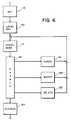
- Fig. 6 is a flow chart that shows the high level sequencing of the illustrative configuration editor.
- initialization activities 110 are performed.
- steps 112 are performed by which the user can enter and edit information describing communication parameters of the local system (i.e., the local system's communication environment).
- Scroll mode 114 After entry of local information 112, scroll mode 114 is entered. Scroll mode 114 permits a user to scan a list of different sets of communication parameters and to make any one of these the current set. Scroll mode 114 is exited when the user presses one of four keys: INSERT key, DELETE key, REPLACE key, or CANCEL key. Following such a key press, branching 116 occurs that directs further processing to one of four operations, depending upon which key was pressed: INSERT key ---> insert operation 118 REPLACE key ---> modify operation 120 DELETE key ---> delete operation 122 CANCEL key ---> cleanup operation 124
- the operations 118, 120, and 122 permit a user to create a new parameter set and add it to the list, modify a listed parameter set, and delete a listed parameter set, respectively.
- the cleanup operation 124 makes preparations for exiting the configuration editor.
- the software implementing the editor is written predominantly in the C programming language, with portions being written in 8086 assembly language.
- Fig. 7 shows major software components of the illustrative configuration editor.
- a module known as "main" 210 is highest level of the editor software.
- the main module 210 employs a set of second level modules 220, 222, 224, 226, 228, 230, and 232 to accomplish the operations indicated in the boxes 110, 112, 114, 118, 120, 122, and 124, respectively, of flow chart shown in Fig. 6; box 116 is directly implemented in main 210.
- These second level modules in turn rely on numerous lower level routines in accomplishing their operations.
- the lower level routines most important in understanding the present invention are organized into three groups: data entry primitives 240, drawing primitives 242, and database access primitives 244.
- communication parameters are grouped into those describing the local communications environment (e.g., what type of modem the local system has available) and those needed to access particular remote systems.
- those needed to access particular remote systems are organized by remote system; these are organized for the user by the name of the remote system to which they apply.
- the configuration editor presents to the user a scrollable list with one entry in the list per remote system. For the convenience of the user, this list is sorted alphabetically by remote system name.
- the illustrative editor does not provide means by which a user can control most of the individual details of the configuration database. This editor is intended to be usable by someone who is unsophisticated with regard to data communications technology. Thus, major alternatives are presented, and as many details as possible are hidden from the user and given values automatically generated by the editor. The vast majority of communication protocol parameters to be stored in the database will be determined by the configuration editor on the basis of that small amount of information entered by the user and automatically determined.
- the data entry primitives 240 include routines for displaying messages at any location on the screen as well as for managing screen-oriented data entry.
- Screen-oriented data entry includes displaying the prompts for various data fields and providing for the user to move the cursor from field to field and change the value of each field.
- Two principle types of fields are supported: fill-in fields and multiple choice fields. Also provided are means by which different data validation operations can be performed for each of the fields.
- the graphics primitives 242 are used to display the various depictions presented to the user. These primitives work on a character-only display. This is possible by using graphics characters provided in the character set (that provide, e.g., horizontal and vertical lines and corners for connecting these) as well as exploiting the graphical character of normal characters. Further, display attributes such as reverse video and underline are exploited as well. For example, period characters in reverse video are used in depicting the external modem, and underlined colons are used in depicting the keyboards of the local and remote systems.
- the graphics primitives 242 include very low level operations such as those that draw or erase vertical and horizontal lines.
- the graphics primitives also provide higher level operations such as those that draw pictures of computer workstations or draw an internal or external modem.
- the graphics primitives 242 display text in addition to graphics.
- the depiction of the local system includes a graphical representation of a Wang LapTop computer together with the phrase "Wang LapTop". (Note that a way to show a screen portion of a display using characters only is to display "Wang LapTop" in reverse video with reverse video spaces on both sides so as to form a rectangular region of reverse video; the Figs. 1-4 do not show this reverse video.)
- the text portion of a depiction is displayed using the message display routines of the data entry primitives 240 (e.g., the system type indication on the screen of the remote system).
- the database primitives 244 include routines that create, update, delete, and access (locate information) records in the configuration database.
- the configuration database stores information about the local system, remote systems, and about protocols for communicating with remote systems. This is accomplished by storing data in records of a variety of types. One can think of this either as each record including a field that identifies the type of the record or the records being stored in a plurality of logical tables, with one table for each record type.
- the detailed implementation of the database is hidden from the higher level software by the database primitives.
- the illustrative configuration database includes the following types of records (illustrative fields are listed for each type of record):
- I. LOCAL SYSTEM NAME is a single record that stores the name of the local system: (A) name of the local system
- ENVIRONMENT RECORDS store information about the local system that may be protocol specific. The number of these records may range from zero to the total number of protocols defined:
- SYSTEM/PROTOCOL LINK RECORDS each indicate that a particular protocol is defined for use by a particular remote system. These are organized by remote system name:
- Other information can be stored in such a database, such as: information about networks; information to support routing of data between systems which have no direct connection to each other; database control information, such as database version number.
- each parameter set in the list seen by the user includes a single remote system and a single protocol; in the database, a single System Record may be linked to a plurality of Protocol Records.
- certain logic is necessary when deleting what the user sees as a single parameter set. For example, when a selection in the scrollable list is deleted, the database is checked to see if there are any other protocols linked to the relevant remote system, and the affected System Record is deleted only if there are no other protocols defined for that system.
- the present invention has been described in the context of point-to-point dial up communications.
- the invention can also be employed in other communications environments, such as local area networks.
- the configuration editor can automatically update the scrollable list to indicate which remote systems are currently connected to the network. In this situation the configuration editor would not permit the user to delete automatically identified remote systems; if a remote system becomes inactive and ceases to be automatically detected, then the user would be permitted to delete that system from the list.
- Add I repeated pressing of the INSERT key can cycle through a list of different protocols; the depiction of the connection can be augmented to visually distinguish among the different possible protocols.
- file transfer operations can be accomplished with the aid of a screen similar to that described above in the context of scroll mode.
- a screen can depict the local system, a remote system, and a connection between, and can have a window for a scrollable list; in this case the scrollable list can be a list of file transfer requests or a list of files available to be transferred.
- the depiction can be augmented with arrows to visually depict the direction of file transfer selected by the user.
- Such a file transfer arrangement can be made available to the user after the scroll mode screen or could be made available completely separate from the configuration editor.
Description
- The present invention relates to user interfaces for computer systems and to methods and apparatus for editing databases of communication configuration parameters.
- Computer communications, like many other uses of computers, typically requires precise set up by a user. Before a task such as "send a message to the Chicago office" can be performed, much preparation is typically required, including the specification of various communication parameters. Such parameters might include the name of the particular Chicago computer system, an access password, its telephone number, the data rate at which its modem operates, and so forth.
- The need for set up flows from the fact that communications systems are typically designed to be relatively flexible; they are designed to work with a range of different system configurations. Some configuration parameters can be automatically determined (e.g., the capabilities of a modem internal to the user's system). However, various aspects of a particular configuration to be used must be specified by a user.
- The nature of the configuration information that a user must provide varies, depending upon the communications environment such as these examples: synchronous and asynchronous communications over switched lines can involve parameters such as data rate, telephone number, delay time between attempts to dial; network communications, both local area networks and wide area networks, can involve parameters such as system names and types, file transfer passwords, and system capabilities (e.g., types of transfers supported).
- While sometimes communication configuration information is embodied implicitly in communications programs, more often such information is stored separate from the body of the program in a configuration database. The task of building and modifying a configuration database is done in various ways, such as:
- (a) If the configuration database is stored as a text file, a general purpose text editor is used to edit the database. Since any existing text editor can be used, no special data entry program need be created. However, this has the disadvantage that while editing the database the user is not provided with any prompts or other database specific guidance.
- (b) If the database is stored using a database subsystem, database data entry screens may be used. These are typically arranged so that each screen corresponds to a record in the database; each screen has fields to be filled in by the user, and these fields correspond to fields in the record to which the screen corresponds.
- (c) A variation on approach (b) is where the data base is sufficiently simple that only a single screen is needed: after the user selects a parameter set to be modified, the current values of that set are displayed (such a display is sometimes called a settings sheet); the user moves the cursor around the screen and changes the parameters to the desired values. Rather than moving the cursor around the screen to change values, two other methods can be used:
- (1) the user types commands to change individual values; or
- (2) the user is sequentially prompted to change or accept every parameter in the set.
- (d) Another approach is to view database modification as a side effect of controlling a communication system. In this case a user issues network control commands which result in changes in a configuration database. The initial version of the database can be generated as part of a system generation procedure; in this case a user provides initial information by means of a text file or by responding to prompts during the generation process.
- One shortcoming of these prior approaches is that they tend to divert the user's attention from the user's intended task of communicating. For example, approach (b) above diverts the user's attention to the task of specifying communication parameters, and the task of specifying communication parameters is further diverted to the task of navigating through the data entry screens for a configuration database; thus, rather than directing attention to the user's initial problem, the user is diverted to a "database problem". Also, the user can easily get lost when deeply embedded in nested menus. Another form of diversion of the user's attention, especially seen in approaches (a) and (d), occurs when the user's attention becomes focused on remembering a vocabulary of command verbs and remembering the command syntax in which these must be used. This problem is aggravated when approach (a) is used, because the probability of typing errors is great and the user must prepare a properly spelled and formatted file.
- An object of the present invention is to provide means by which a user can, with little concern for communications details, easily specify needed communication parameters.
- According to the present invention as set forth in claims 1 and 3, a display is presented to a user that helps the user understand the context in which requested information is relevant. The user's system (also referred to as the local system) is depicted on the screen. Another system is also depicted, along with a visual indication of a connection to the user's system. Thus, the screen display reminds the user that the task being addressed is communication between the user's system and some other system. The meaning of some communication parameters are visually depicted, aiding the user in understanding and remembering the significance of these parameter settings. A list of parameter sets is displayed in a portion of the screen so as not to obscure the depiction. The depiction is updated to represent the current values of the currently selected set of parameters. When parameters are being entered or changed, the context in which the prompts are presented enhances the meaning of the prompts.
- The invention is pointed out with particularity in the appended claims. The above and other advantages of the invention may be better understood by referring to the following detailed description in conjunction with the drawing, in which:
- Figs. 1, 2, 3, and 4
- show various screen displays produced by an illustrative configuration editor according to the present invention;
- Fig. 5
- is a state transition table showing the relationship between certain user keystrokes and major display events;
- Fig. 6
- is a flow chart showing the sequence of operations of the configuration editor; and
- Fig. 7
- shows major components of software implementing the configuration editor.
- A computer program known as a configuration editor is used in practicing the present invention. This program runs on a general purpose computer system (such as the Wang LapTop computer) and a user interacts with the system by use of a keyboard and a display screen. This computer system is known as the local computer system that is to be involved in communication with one or more remote systems. The configuration editor is used to create and modify a database that is used by various communications facilities such as file transfer and terminal emulation according to various predefined protocols that are part of a collection known as Wang Systems Networking.
- Figs. 1-4, show examples of the screen display at various times during the operation of an illustrative configuration editor. The configuration editor initially displays previously defined information and collects new information and modifications from the user about the local system's communication environment. The editor then enters a scroll mode which enables the user to review previously collected information about remote systems, modify this information, and enter new information about remote systems.
- When the configuration editor is started on a system that has no existing communications configuration database, the user is presented with a screen display as shown in Fig. 1. When the editor is started on subsequent occasions (i.e., when there is an existing database), a display like in Fig. 1 is displayed that includes whatever values are present in the database for the displayed fields; in other words, the relevant information from that database would be displayed in place of the blanks shown in Fig. 1 and the
selection block 322 would be set to the selection indicated in the database. - On this initial screen, a message is displayed indicating that the local system is being tested to determine if an internal modem is present in the system. The automatic detection of an internal modem is an example of how the illustrative configuration editor, where possible, automatically acquires information. Another example of automatic acquisition of information is where the local system is actively connected to a communications network, in which case it is possible to acquire information about the other systems actively connected to the network. Having acquired information automatically, the editor need not prompt the user for this information. It may be possible to detect an externally connected modem. However, in this illustrative embodiment the user is prompted to enter information about an external modem, rather than gathering such information automatically. This is because external modems are so easily changed (especially if the local system is a portable computer); also, in this way, configuration can be performed at a time when the external modem is not plugged in.
- On the initial screen, shown in Fig. 1, is depicted the user's
local system 310 and anexternal modem 320. The screen includes three data entry fields: a local system name, a password to be used by remote systems seeking to transfer files with the local system, and an external modem specification. The user can move among the fields by pressing the ENTER key. The first two fields are fill-in fields, into which the user enters text. The third field is a multiple choice field: a selection block 322 (shown in Fig. 1 selecting "None") can be moved by the user (by use of the space bar, or the first letter of a selection) among the selections. When the contents of all three of these fields is acceptable to the user, the user presses the EXEC key. - In response to the user pressing the EXEC key at the initial screen, the screen display is modified in ways that depend on the information remaining to be collected regarding the local system. If there is an external auto-dial modem then the user is prompted for further information about the local system environment as shown in Fig. 2: dial type (pulse or tone) (a property of the telephone exchange to which the user's telephone line is connected) and maximum speed of the external modem. If there is only an internal modem whose characteristics have been automatically detected, then the only further information about the local system for which the user is prompted is the dial type (assuming the internal modem is determined to have auto dial capability).
- A characteristic of the present system is that the prompts presented to the user are adjusted in light of previously acquired information. For example, if there is only a manual dial modem, then when defining the local environment the user is not prompted for the dial type (pulse or tone) and when defining a remote system the user is not prompted for telephone number.
- In response to pressing the EXEC key at the screen of Fig. 2, a screen like that shown in Fig. 3 is displayed. This screen indicates to the user that the editor is in scroll mode. In scroll mode the user can scroll the list of information about remote systems (by use of arrow keys or PREV and NEXT keys) and the user can branch to insert, delete, or modify operations (by other key presses, described below). In the present example, the communication parameters are organized for the user into sets according to remote systems -- i.e., each set includes parameters for connecting to a particular remote system. One of the parameter sets in the list is the currently selected set; by scrolling through the list, the user can make any one of the sets the current selection.
- The scroll screen, shown in Fig. 3, includes a window in which is displayed information from up to three sets of communication parameters. The user can see information about all of the existing parameter sets by scrolling through this list. The current selection from the list is emphasized by being displayed in reverse video or other in another way visually highlighted; thus, in scroll mode, the connection depicted always corresponds to the current selection from the list.
- The scroll screen also depicts the
local system 310, aremote system 360, and aconnection external modem 320 and aphone jack 330 and communication lines from the local system to themodem 342, from the modem to thephone jack 344, and (with distance indicated by a break in the line bounded by parallel bars 346) from the phone jack to the remote system. If the current parameter set in the scrollable list specified use of an internal modem, then the internal modem would be depicted and a connection from the internal modem to the phone jack would be depicted in place of connections from the local system to the external modem and from the external modem to the phone jack. Changes in the current selection results in updating the depiction of the connection and the remote system. - From this screen (Fig. 3), by pressing the appropriate key the user can elect to modify one of the existing parameter sets (the REPLC key), create a new parameter set (the INSERT key), delete a parameter set (the DELETE key), or exit from the configuration editor (the CANCEL key).
- When the DELETE key is pressed, the user is asked whether or not the parameter set represented by the current selection from the scrollable list is to be deleted from the configuration database. If the user confirms this, then the configuration editor modifies the database.
- When the INSERT key is pressed, a screen somewhat like that shown in Fig. 4 is displayed; the multiple choice field "Duplex" and the fill-in fields "Remote System", "File Transfer Password", and "Phone Number" would not yet be displayed. (Also, if the INSERT key was pressed at the screen exactly as shown in Fig. 3, then the connection depicted would go via the
external modem 320, rather than theinternal modem 350, because that was the current connection shown.) At this point pressing the INSERT key switches the depicted connection among the available alternatives: because in the present example there are only two types of connections (via the internal modem or via the external modem), the INSERT key has a toggling action; if more than two connections were available then repeated pressing of the INSERT key would sequentially step through each of the possible connections. When the desired connection is depicted, the user presses the EXEC key. At this time, fields for additional information are displayed, as shown in Fig. 4 (e.g., "Duplex", "Remote System", "File Transfer Password", and "Phone Number"). After the user is satisfied with the information entered in these fields, the user presses the EXEC key resulting in the addition of information to the configuration database corresponding to the parameters just entered. - When the REPLC key is pressed at a screen like that of Fig. 3, then a screen similar to that of Fig. 4 is displayed in which the fields are filled with the values from the current parameter set and the connection shown corresponds to that specified in the current parameter set. The user can modify the values displayed in the various fields and then press the EXEC key to cause the modifications to be incorporated into the configuration database. In the illustrative editor, the type of connection (i.e., via internal or external modem) cannot be changed; thus during the modify operation there is no screen corresponding to Add I in Fig. 5.
- What has been discussed above as a series of screens (examples of which are shown in Figs. 1-4) could also be understood to be a single evolving screen. For example, the depiction of the local system is always present on the screen in the same location; in fact, once on the screen, the local system depiction need not be redrawn. Other parts of the depiction of the communications connection and remote system generally stay on the screen, too.
- Another characteristic of the screen display is a fixed size window at the bottom of the screen in which is displayed helpful information about what actions are currently bound to selected keys and a statement of the type of action the configuration editor expects the user is currently taking. At the top of the screen is a heading that also provides helpful information about the current state of the configuration editor.
- Fig. 5 summarizes the relationship between key strokes and screen display in a table having four columns, which are titled:
- (a) SCREEN STATE,
- (b) KEY,
- (c) NEXT,
- (d) COMMENTS / ADDITIONAL CONDITIONS.
- In the first column are listed the major screen states. In the second column are listed keys that a user can press; in the second column a group of keys are listed for each of the screen states in the first column. In the third column are listed the next screen state that results from the user pressing the corresponding key indicated in the second column. In some cases a particular key can result in one of several possible screen states, depending upon some further condition; such further conditions are identified in the fourth column of the table. The fourth column also includes some comments about actions that are taken in addition to changing the state of the screen display.
- The screen displays shown in the Figs. 1-4 correspond to screen states in the table of Fig. 5 as follows:
- Fig. 1 is Local I
- Fig. 2 is Local II
- Fig. 3 is Scroll
- Fig. 4 is Add II
- Fig. 6 is a flow chart that shows the high level sequencing of the illustrative configuration editor. When the configuration editor is started,
initialization activities 110 are performed. Followinginitialization 110, a series ofsteps 112 are performed by which the user can enter and edit information describing communication parameters of the local system (i.e., the local system's communication environment). - After entry of
local information 112,scroll mode 114 is entered.Scroll mode 114 permits a user to scan a list of different sets of communication parameters and to make any one of these the current set.Scroll mode 114 is exited when the user presses one of four keys: INSERT key, DELETE key, REPLACE key, or CANCEL key. Following such a key press, branching 116 occurs that directs further processing to one of four operations, depending upon which key was pressed:
INSERT key --->insert operation 118
REPLACE key ---> modifyoperation 120
DELETE key --->delete operation 122
CANCEL key --->cleanup operation 124 - The
operations cleanup operation 124 makes preparations for exiting the configuration editor. - The software implementing the editor is written predominantly in the C programming language, with portions being written in 8086 assembly language.
- Fig. 7 shows major software components of the illustrative configuration editor. A module known as "main" 210 is highest level of the editor software. The
main module 210 employs a set ofsecond level modules boxes box 116 is directly implemented in main 210. These second level modules in turn rely on numerous lower level routines in accomplishing their operations. The lower level routines most important in understanding the present invention are organized into three groups:data entry primitives 240, drawingprimitives 242, anddatabase access primitives 244. - In the illustrative configuration editor, communication parameters are grouped into those describing the local communications environment (e.g., what type of modem the local system has available) and those needed to access particular remote systems. As far as the user is concerned, those needed to access particular remote systems are organized by remote system; these are organized for the user by the name of the remote system to which they apply. The configuration editor presents to the user a scrollable list with one entry in the list per remote system. For the convenience of the user, this list is sorted alphabetically by remote system name.
- The illustrative editor does not provide means by which a user can control most of the individual details of the configuration database. This editor is intended to be usable by someone who is unsophisticated with regard to data communications technology. Thus, major alternatives are presented, and as many details as possible are hidden from the user and given values automatically generated by the editor. The vast majority of communication protocol parameters to be stored in the database will be determined by the configuration editor on the basis of that small amount of information entered by the user and automatically determined.
- The
data entry primitives 240 include routines for displaying messages at any location on the screen as well as for managing screen-oriented data entry. Screen-oriented data entry includes displaying the prompts for various data fields and providing for the user to move the cursor from field to field and change the value of each field. Two principle types of fields are supported: fill-in fields and multiple choice fields. Also provided are means by which different data validation operations can be performed for each of the fields. - The
graphics primitives 242 are used to display the various depictions presented to the user. These primitives work on a character-only display. This is possible by using graphics characters provided in the character set (that provide, e.g., horizontal and vertical lines and corners for connecting these) as well as exploiting the graphical character of normal characters. Further, display attributes such as reverse video and underline are exploited as well. For example, period characters in reverse video are used in depicting the external modem, and underlined colons are used in depicting the keyboards of the local and remote systems. - The
graphics primitives 242 include very low level operations such as those that draw or erase vertical and horizontal lines. The graphics primitives also provide higher level operations such as those that draw pictures of computer workstations or draw an internal or external modem. - The
graphics primitives 242 display text in addition to graphics. For example, the depiction of the local system includes a graphical representation of a Wang LapTop computer together with the phrase "Wang LapTop". (Note that a way to show a screen portion of a display using characters only is to display "Wang LapTop" in reverse video with reverse video spaces on both sides so as to form a rectangular region of reverse video; the Figs. 1-4 do not show this reverse video.) In some cases the text portion of a depiction is displayed using the message display routines of the data entry primitives 240 (e.g., the system type indication on the screen of the remote system). - The
database primitives 244 include routines that create, update, delete, and access (locate information) records in the configuration database. - The configuration database stores information about the local system, remote systems, and about protocols for communicating with remote systems. This is accomplished by storing data in records of a variety of types. One can think of this either as each record including a field that identifies the type of the record or the records being stored in a plurality of logical tables, with one table for each record type. The detailed implementation of the database is hidden from the higher level software by the database primitives.
- The illustrative configuration database includes the following types of records (illustrative fields are listed for each type of record):
-
- (A) protocol type
- (B) rate to use with an external modem
- (C) rate to use with an internal modem
- (D) dial type - e.g., pulse or tone
- (E) external modem type - e.g., none, auto-dial, manual dial
- (F) internal modem type - e.g., none, auto-dial, manual dial
- (G) external modem - Has there ever been an external modem?
- (H) internal modem - Has there ever been an internal modem?
-
- (A) name of remote system
- (B) remote system identifier
- (C) type of remote system
- (D) password to access the remote system
-
- (A) remote system identifier
- (B) name of remote system
-
- (A) protocol identifier
- (B) protocol name
- (C) protocol type - e.g., synchronous, asynchronous, X.21, Telenet
- (D) port address - slot with interface board and port # on the board
- (E) enabled - permits protocol to be disabled without removing its definition from the database
- (F) base cost of the protocol - for use in routing
- (G) link type - e.g, switched, dedicated, leased
- (H) role - e.g., primary/secondary or peer-to-peer
- (I) modem rate
- (J) modem option - e.g., full duplex, half duplex
- (K) call direction - e.g., in, out, both
- (L) inbound packet size - e.g., 128, 256, 512
- (M) outbound packet size - e.g., 128, 256, 512
- (N) parameter negotiate - yes or no
- (O) sync character - e.g., hex 16
- (P) stop bits - e.g., 1, 1.5, 2
- (Q) parity enable - e.g., yes or no
- (R) parity type - e.g., even, odd
- (S) retry count for redialing
- (T) delay time between retries
-
- (A) protocol name
- (B) protocol identifier
-
- (A) remote system name
- (B) protocol name
-
- (A) protocol identifier
- (B) remote system identifier
- (C) protocol specific data such as:
- (a) telephone number
- (b) override - defaults overridden if true
- (c) retry count for redialing
- (d) delay time between retries
- (e) modem rate
- (f) modem option - e.g., full duplex, half duplex
- (g) use internal or external modem
- (h) autodial - e.g., autodial, manual dial, null modem
- Other information can be stored in such a database, such as: information about networks; information to support routing of data between systems which have no direct connection to each other; database control information, such as database version number.
- Note that there is not a one-to-one correspondence between records in the database and parameter sets in the scrollable list seen by the user: each parameter set in the list seen by the user includes a single remote system and a single protocol; in the database, a single System Record may be linked to a plurality of Protocol Records. Thus, certain logic is necessary when deleting what the user sees as a single parameter set. For example, when a selection in the scrollable list is deleted, the database is checked to see if there are any other protocols linked to the relevant remote system, and the affected System Record is deleted only if there are no other protocols defined for that system.
- The present invention has been described in the context of point-to-point dial up communications. The invention can also be employed in other communications environments, such as local area networks. When connected to certain local area networks, the configuration editor can automatically update the scrollable list to indicate which remote systems are currently connected to the network. In this situation the configuration editor would not permit the user to delete automatically identified remote systems; if a remote system becomes inactive and ceases to be automatically detected, then the user would be permitted to delete that system from the list.
- In some situations and for some types of users it may be advantageous to permit the user to select among a variety of communication protocols. For example, this can be accommodated at the screen state referred to above as Add I: repeated pressing of the INSERT key can cycle through a list of different protocols; the depiction of the connection can be augmented to visually distinguish among the different possible protocols.
- In addition to aiding in the specification of communication parameters, the present invention can be used advantageously in accomplishing the communications operations themselves. For example, file transfer operations can be accomplished with the aid of a screen similar to that described above in the context of scroll mode. Such a screen can depict the local system, a remote system, and a connection between, and can have a window for a scrollable list; in this case the scrollable list can be a list of file transfer requests or a list of files available to be transferred. The depiction can be augmented with arrows to visually depict the direction of file transfer selected by the user. Such a file transfer arrangement can be made available to the user after the scroll mode screen or could be made available completely separate from the configuration editor.
Claims (4)
- Apparatus for specifying and editing communication parameters for controlling communications operations between a local system (310) and a remote system (360), the local system including a database for storing the communications parameters, a display device for presenting displays to a user for specifying and editing communications parameters, an input means for entering or selecting communications parameters, and a communications parameter editor coupled to the database, the display device and the input means for specifying and editing communications parameters for communication configurations, each communications configuration including communications elements comprising a communications connection between the local system and a remote system and the parameters for the communications elements of the configuration,
the communications parameter editor being characterized by:
a database editor connected from the input means and responsive to an input identifying a selected communication configuration for accessing the database to read from the database the communications elements and parameters for the identified communication configuration,
the parameters including a first set of parameters which are defined by a user, a second set of parameters which are determined by the communications parameter editor from the first set of parameters and a set of selectable values for each first parameter,
a current configuration means being responsive to the identified configuration for determining from the database and identifying
currently defined communications elements of the identified configuration and
currently defined first parameters of the identified configuration, and
communications elements and first parameters which are not defined for the identified configuration,
a configuration representation generator,
the configuration representation generator being responsive to the database editor for generating
data representing the currently defined communications elements and first parameters of the identified configuration,
data representing the currently undefined communications elements and first parameters of the identified configuration, and
data representing a set of selectable communications elements for each communications element and a set of selectable parameter values for each first parameter of the currently defined communications elements,
the configuration representation generator being connected from the input means and to the display device and responsive to a communications element selection inputs from the input means for providing to the display device
the data representing the currently defined communications elements of the identified configuration,
for a selected defined or undefined communications element identified by the communications element input, the set of selectable communications elements for the selected communications element, and
upon selection of a selectable communications element, the set of first parameter values for the selected communications element,
the database editor being responsive to inputs selecting a communications element and first parameter values for the selected communications element for
determining the second parameters related to the first parameters,
writing the definitions of the selected communications element and corresponding first and second parameter values into the database, and
the configuration representation generator being responsive to the definitions of the selected communications element and corresponding first and second parameter values into the database for updating the data provided to the display device. - The communications parameter editor of claim 1,
wherein the database editor is further characterized by:
an automatic configuration detector for
scanning the local system and identifying currently active communications elements connected to the local system and the first parameters of the identified currently active communications elements and
providing to the configuration representation generator the definitions of the currently active communications elements and the first parameters of the currently active communications elements. - A method for specifying and editing communication parameters for controlling communications operations between a local system (310) and a remote system (360), the local system including a database for storing the communication parameters, a display device for presenting displays to a user for specifying and editing communications parameters, an input means for entering or selecting communications parameters, and a communications parameter editor coupled to the database, the display device,and the input means for specifying and editing communications parameters for communication configurations, each communications configuration including communications elements comprising a communications connection between the local system and a remote system and the parameters for the communications elements of the configuration,
characterized by the steps of:(a) in response to an input identifying a selected communication configuration, accessing the database to read from the database the communications elements and parameters for the identified communication configuration,
the parameters including a first set of parameters which are defined by a user, a second set of parameters which are determined by the communications parameter editor from the first set of parameters and a set of selectable values for each first parameter,(b) determining from the database and identifying(1) currently defined communications elements of the identified configuration(2) currently defined first parameters of the identified configuration, and(3) communications elements and first parameters which are not defined for the identified configuration,(c) generating(1) data representing the currently defined communications elements and first parameters of the identified configuration,(2) data representing the currently undefined communications elements and first parameters of the identified configuration, and(3) data representing a set of selectable communications elements for each communications element and a set of selectable parameter values for each first parameter of the currently defined communications elements,(d) providing to a display device(1) the data representing the currently defined communications elements of the identified configuration,(2) for a selected defined or undefined communications element identified by the communications element input, the set of selectable communications elements for the selected communications element, and(3) upon selection of a selectable communications element, the set of first parameter values for the selected communications element, and(e) in response to inputs selecting a communications element and first parameter values for the selected communications element(1) determining the second parameters related to the first parameters and(2) writing the definitions of the selected communications element and corresponding first and second parameter values into the database, and(3) updating the data generated and provided to the display device. - The method of claim 3, wherein the step of determining currently defined communications elements and first parameters is further characterized by the step of:
scanning the local system and identifying currently active communications elements connected to the local system and the first parameters of the identified currently active communications elements and
providing to the configuration representation generator the definitions of the currently active communications elements and the first parameters of the currently active communications elements.
Applications Claiming Priority (2)
| Application Number | Priority Date | Filing Date | Title |
|---|---|---|---|
| US07/020,838 US4942540A (en) | 1987-03-02 | 1987-03-02 | Method an apparatus for specification of communication parameters |
| US20838 | 1987-03-02 |
Publications (3)
| Publication Number | Publication Date |
|---|---|
| EP0281102A2 EP0281102A2 (en) | 1988-09-07 |
| EP0281102A3 EP0281102A3 (en) | 1990-04-25 |
| EP0281102B1 true EP0281102B1 (en) | 1995-04-12 |
Family
ID=21800873
Family Applications (1)
| Application Number | Title | Priority Date | Filing Date |
|---|---|---|---|
| EP88103170A Expired - Lifetime EP0281102B1 (en) | 1987-03-02 | 1988-03-02 | Method and apparatus for specification of cummunication parameters |
Country Status (6)
| Country | Link |
|---|---|
| US (1) | US4942540A (en) |
| EP (1) | EP0281102B1 (en) |
| JP (1) | JP2653816B2 (en) |
| AU (1) | AU605216B2 (en) |
| CA (1) | CA1291270C (en) |
| DE (1) | DE3853550T2 (en) |
Families Citing this family (122)
| Publication number | Priority date | Publication date | Assignee | Title |
|---|---|---|---|---|
| US4942540A (en) * | 1987-03-02 | 1990-07-17 | Wang Laboratories, Inc. | Method an apparatus for specification of communication parameters |
| US5345587A (en) * | 1988-09-14 | 1994-09-06 | Digital Equipment Corporation | Extensible entity management system including a dispatching kernel and modules which independently interpret and execute commands |
| US5589849A (en) * | 1989-07-03 | 1996-12-31 | Ditzik; Richard J. | Display monitor position adjustment apparatus |
| CA2017458C (en) * | 1989-07-24 | 2000-10-10 | Jonathan R. Engdahl | Intelligent network interface circuit |
| JP2938104B2 (en) * | 1989-11-08 | 1999-08-23 | 株式会社日立製作所 | Shared resource management method and information processing system |
| WO1991007719A2 (en) * | 1989-11-13 | 1991-05-30 | Digital Equipment Corporation | User interface for management |
| US5289585A (en) * | 1990-03-26 | 1994-02-22 | Siemens Nixdorf Informationssysteme Ag | Multiprocessor system having a system bus for the coupling of several processing units with appertaining private cache memories and a common main memory |
| US5446897A (en) * | 1990-08-31 | 1995-08-29 | International Business Machines Corporation | Automated address discovery method and apparatus for local area networks |
| JPH0727504B2 (en) * | 1990-12-10 | 1995-03-29 | インターナショナル・ビジネス・マシーンズ・コーポレイション | System for defining network configuration, method for generating configuration parameters for network, and system for configuring network |
| US6577324B1 (en) | 1992-06-03 | 2003-06-10 | Compaq Information Technologies Group, L.P. | Video and audio multimedia pop-up documentation by performing selected functions on selected topics |
| US5475421A (en) * | 1992-06-03 | 1995-12-12 | Digital Equipment Corporation | Video data scaling for video teleconferencing workstations communicating by digital data network |
| US5623690A (en) * | 1992-06-03 | 1997-04-22 | Digital Equipment Corporation | Audio/video storage and retrieval for multimedia workstations by interleaving audio and video data in data file |
| US5594859A (en) * | 1992-06-03 | 1997-01-14 | Digital Equipment Corporation | Graphical user interface for video teleconferencing |
| US5375068A (en) * | 1992-06-03 | 1994-12-20 | Digital Equipment Corporation | Video teleconferencing for networked workstations |
| GB9215320D0 (en) * | 1992-07-18 | 1992-09-02 | Int Computers Ltd | Configuration mechanism for a computer system |
| US5905494A (en) * | 1992-08-12 | 1999-05-18 | International Business Machines Corporation | Method and system within an object oriented programming environment for enhanced efficiency of entry of operator inputs utilizing a complex object |
| US5455853A (en) * | 1992-08-25 | 1995-10-03 | Bell Communications Research, Inc. | Method of creating a telecommunication service template |
| US5463682A (en) * | 1992-08-25 | 1995-10-31 | Bell Communications Research, Inc. | Method of creating user-defined call processing procedures |
| US5442690A (en) * | 1992-08-25 | 1995-08-15 | Bell Communications Research, Inc. | Telecommunication service record structure and method of execution |
| WO1994005112A1 (en) * | 1992-08-25 | 1994-03-03 | Bell Communications Research, Inc. | System and method for creating, transferring, and monitoring services in a telecommunication system |
| US5511116A (en) * | 1992-08-25 | 1996-04-23 | Bell Communications Research Inc. | Method of creating and accessing value tables in a telecommunication service creation and execution environment |
| US5452413A (en) * | 1992-12-18 | 1995-09-19 | International Business Machines Corporation | Method and system for manipulating wide-angle images |
| CA2116278C (en) * | 1993-03-01 | 2000-07-25 | Robert O. Quinn | Graphical interface for cellular system |
| US6738357B1 (en) | 1993-06-09 | 2004-05-18 | Btg International Inc. | Method and apparatus for multiple media digital communication system |
| AU677393B2 (en) * | 1993-07-08 | 1997-04-24 | E-Talk Corporation | Method and system for transferring calls and call-related data between a plurality of call centres |
| US5937051A (en) * | 1993-07-08 | 1999-08-10 | Teknekron Infoswitch Corporation | Method and system for transferring calls and call-related data between a plurality of call centers |
| EP0657810B1 (en) | 1993-12-06 | 2001-02-28 | Canon Kabushiki Kaisha | User-definable interactive system |
| JPH07306803A (en) * | 1994-03-24 | 1995-11-21 | At & T Global Inf Solutions Internatl Inc | Secret protective face of computer-resource storage part |
| EP0760187B1 (en) * | 1994-05-19 | 2002-07-31 | BRITISH TELECOMMUNICATIONS public limited company | File transfer mechanism |
| US5852825A (en) * | 1994-12-05 | 1998-12-22 | Trimble Navigation Limited | Form data message formatting method, program and system |
| US6041044A (en) * | 1995-01-19 | 2000-03-21 | International Business Machines Corporation | Control network and configuration method therefor |
| US5854898A (en) | 1995-02-24 | 1998-12-29 | Apple Computer, Inc. | System for automatically adding additional data stream to existing media connection between two end points upon exchange of notifying and confirmation messages therebetween |
| US5577103A (en) * | 1995-03-10 | 1996-11-19 | Telefonaktiebolaget Lm Ericsson | Method of providing service information to subscribers in a cellular telecommunications network using the short message service (SMS) |
| US5608854A (en) * | 1995-04-25 | 1997-03-04 | Motorola, Inc. | Method and apparatus for displaying information in a communication system |
| US5918039A (en) * | 1995-12-29 | 1999-06-29 | Wyse Technology, Inc. | Method and apparatus for display of windowing application programs on a terminal |
| US7720672B1 (en) | 1995-12-29 | 2010-05-18 | Wyse Technology Inc. | Method and apparatus for display of windowing application programs on a terminal |
| AU766791B2 (en) * | 1995-12-29 | 2003-10-23 | Wyse Technology L.L.C. | A method for updating operating characteristics of a terminal |
| GB2351893B (en) * | 1995-12-29 | 2001-02-28 | Wyse Technology Inc | Method and apparatus for display of windowing application programs on a terminal |
| US6219708B1 (en) * | 1996-05-30 | 2001-04-17 | Multi-Tech Systems, Inc. | System for network resource management |
| US5915010A (en) | 1996-06-10 | 1999-06-22 | Teknekron Infoswitch | System, method and user interface for data announced call transfer |
| US5999180A (en) * | 1996-09-04 | 1999-12-07 | Ncr Corporation | Method and system for generating a configuration file using an X-windows server configuration tool |
| US5991761A (en) * | 1997-01-10 | 1999-11-23 | Bmc Software, Inc. | Method of reorganizing a data entry database |
| US6295556B1 (en) | 1997-11-18 | 2001-09-25 | Microsoft Corporation | Method and system for configuring computers to connect to networks using network connection objects |
| US6370154B1 (en) | 1997-12-30 | 2002-04-09 | Alcatel Usa Sourcing, L.P. | Telecommunications system craft interface device with broadband end-to-end cross-connect capability |
| US6307546B1 (en) | 1997-12-30 | 2001-10-23 | Alcatel Usa Sourcing, L.P. | Telecommunications system craft interface device with parser having object-oriented state machine |
| US6157968A (en) * | 1998-01-26 | 2000-12-05 | Motorola Inc. | Interface with selector receiving control words comprising device identifiers for determining corresponding communications parameter set for interface port transfer of data words to peripheral devices |
| DE19834321A1 (en) | 1998-07-30 | 2000-02-03 | Alcatel Sa | Method, terminal, node, program module and user interface for determining features required for a communication relationship |
| US6971110B1 (en) * | 2000-02-19 | 2005-11-29 | Hewlett-Packard Development Company, L.P. | System and method to pace event sharing collaboration across multiple distributed applications |
| US6880086B2 (en) | 2000-05-20 | 2005-04-12 | Ciena Corporation | Signatures for facilitating hot upgrades of modular software components |
| US20020116485A1 (en) * | 2001-02-21 | 2002-08-22 | Equipe Communications Corporation | Out-of-band network management channels |
| US7225244B2 (en) * | 2000-05-20 | 2007-05-29 | Ciena Corporation | Common command interface |
| US7266595B1 (en) | 2000-05-20 | 2007-09-04 | Ciena Corporation | Accessing network device data through user profiles |
| US7222147B1 (en) | 2000-05-20 | 2007-05-22 | Ciena Corporation | Processing network management data in accordance with metadata files |
| US7111053B1 (en) | 2000-05-20 | 2006-09-19 | Ciena Corporation | Template-driven management of telecommunications network via utilization of operations support services clients |
| US7143153B1 (en) | 2000-11-09 | 2006-11-28 | Ciena Corporation | Internal network device dynamic health monitoring |
| US20020001307A1 (en) * | 2000-05-20 | 2002-01-03 | Equipe Communications Corporation | VPI/VCI availability index |
| US7240364B1 (en) | 2000-05-20 | 2007-07-03 | Ciena Corporation | Network device identity authentication |
| US7062642B1 (en) | 2000-05-20 | 2006-06-13 | Ciena Corporation | Policy based provisioning of network device resources |
| US7054272B1 (en) | 2000-07-11 | 2006-05-30 | Ciena Corporation | Upper layer network device including a physical layer test port |
| US6742134B1 (en) | 2000-05-20 | 2004-05-25 | Equipe Communications Corporation | Maintaining a local backup for data plane processes |
| US6601186B1 (en) | 2000-05-20 | 2003-07-29 | Equipe Communications Corporation | Independent restoration of control plane and data plane functions |
| US6868092B1 (en) | 2000-05-20 | 2005-03-15 | Ciena Corporation | Network device with embedded timing synchronization |
| US6639910B1 (en) | 2000-05-20 | 2003-10-28 | Equipe Communications Corporation | Functional separation of internal and external controls in network devices |
| US6654903B1 (en) | 2000-05-20 | 2003-11-25 | Equipe Communications Corporation | Vertical fault isolation in a computer system |
| US6876652B1 (en) | 2000-05-20 | 2005-04-05 | Ciena Corporation | Network device with a distributed switch fabric timing system |
| US6332198B1 (en) | 2000-05-20 | 2001-12-18 | Equipe Communications Corporation | Network device for supporting multiple redundancy schemes |
| US6760339B1 (en) | 2000-05-20 | 2004-07-06 | Equipe Communications Corporation | Multi-layer network device in one telecommunications rack |
| US7349960B1 (en) | 2000-05-20 | 2008-03-25 | Ciena Corporation | Throttling distributed statistical data retrieval in a network device |
| US6708291B1 (en) | 2000-05-20 | 2004-03-16 | Equipe Communications Corporation | Hierarchical fault descriptors in computer systems |
| US6671699B1 (en) | 2000-05-20 | 2003-12-30 | Equipe Communications Corporation | Shared database usage in network devices |
| US7020696B1 (en) | 2000-05-20 | 2006-03-28 | Ciena Corp. | Distributed user management information in telecommunications networks |
| US6658580B1 (en) | 2000-05-20 | 2003-12-02 | Equipe Communications Corporation | Redundant, synchronous central timing systems with constant master voltage controls and variable slave voltage controls |
| US7039046B1 (en) | 2000-05-20 | 2006-05-02 | Ciena Corporation | Network device including central and distributed switch fabric subsystems |
| US6934749B1 (en) | 2000-05-20 | 2005-08-23 | Ciena Corporation | Tracking distributed data retrieval in a network device |
| US6715097B1 (en) | 2000-05-20 | 2004-03-30 | Equipe Communications Corporation | Hierarchical fault management in computer systems |
| US6658579B1 (en) | 2000-05-20 | 2003-12-02 | Equipe Communications Corporation | Network device with local timing systems for automatic selection between redundant, synchronous central timing systems |
| US7225240B1 (en) | 2000-05-20 | 2007-05-29 | Ciena Corporation | Decoupling processes from hardware with logical identifiers |
| US7280529B1 (en) | 2000-05-20 | 2007-10-09 | Ciena Corporation | Providing network management access through user profiles |
| US7051097B1 (en) | 2000-05-20 | 2006-05-23 | Ciena Corporation | Embedded database for computer system management |
| US7023845B1 (en) | 2000-06-13 | 2006-04-04 | Ciena Corporation | Network device including multiple mid-planes |
| US6724220B1 (en) | 2000-10-26 | 2004-04-20 | Cyress Semiconductor Corporation | Programmable microcontroller architecture (mixed analog/digital) |
| US8149048B1 (en) | 2000-10-26 | 2012-04-03 | Cypress Semiconductor Corporation | Apparatus and method for programmable power management in a programmable analog circuit block |
| US8160864B1 (en) | 2000-10-26 | 2012-04-17 | Cypress Semiconductor Corporation | In-circuit emulator and pod synchronized boot |
| US7765095B1 (en) | 2000-10-26 | 2010-07-27 | Cypress Semiconductor Corporation | Conditional branching in an in-circuit emulation system |
| US8103496B1 (en) | 2000-10-26 | 2012-01-24 | Cypress Semicondutor Corporation | Breakpoint control in an in-circuit emulation system |
| US8176296B2 (en) | 2000-10-26 | 2012-05-08 | Cypress Semiconductor Corporation | Programmable microcontroller architecture |
| US7263597B2 (en) * | 2001-04-19 | 2007-08-28 | Ciena Corporation | Network device including dedicated resources control plane |
| US7406674B1 (en) | 2001-10-24 | 2008-07-29 | Cypress Semiconductor Corporation | Method and apparatus for generating microcontroller configuration information |
| US7143360B1 (en) * | 2001-10-29 | 2006-11-28 | Cypress Semiconductor Corporation | Pin-out connections/drive levels direct-set by drop down list |
| US8078970B1 (en) | 2001-11-09 | 2011-12-13 | Cypress Semiconductor Corporation | Graphical user interface with user-selectable list-box |
| US8042093B1 (en) | 2001-11-15 | 2011-10-18 | Cypress Semiconductor Corporation | System providing automatic source code generation for personalization and parameterization of user modules |
| US8069405B1 (en) | 2001-11-19 | 2011-11-29 | Cypress Semiconductor Corporation | User interface for efficiently browsing an electronic document using data-driven tabs |
| US6971004B1 (en) | 2001-11-19 | 2005-11-29 | Cypress Semiconductor Corp. | System and method of dynamically reconfiguring a programmable integrated circuit |
| US7770113B1 (en) | 2001-11-19 | 2010-08-03 | Cypress Semiconductor Corporation | System and method for dynamically generating a configuration datasheet |
| US7774190B1 (en) | 2001-11-19 | 2010-08-10 | Cypress Semiconductor Corporation | Sleep and stall in an in-circuit emulation system |
| US7844437B1 (en) | 2001-11-19 | 2010-11-30 | Cypress Semiconductor Corporation | System and method for performing next placements and pruning of disallowed placements for programming an integrated circuit |
| US8103497B1 (en) | 2002-03-28 | 2012-01-24 | Cypress Semiconductor Corporation | External interface for event architecture |
| US7308608B1 (en) | 2002-05-01 | 2007-12-11 | Cypress Semiconductor Corporation | Reconfigurable testing system and method |
| US7761845B1 (en) | 2002-09-09 | 2010-07-20 | Cypress Semiconductor Corporation | Method for parameterizing a user module |
| US7400714B2 (en) * | 2002-12-09 | 2008-07-15 | Murata Kikai Kabushiki Kaisha | Communication device and management server |
| US7295049B1 (en) | 2004-03-25 | 2007-11-13 | Cypress Semiconductor Corporation | Method and circuit for rapid alignment of signals |
| US8286125B2 (en) | 2004-08-13 | 2012-10-09 | Cypress Semiconductor Corporation | Model for a hardware device-independent method of defining embedded firmware for programmable systems |
| US8069436B2 (en) | 2004-08-13 | 2011-11-29 | Cypress Semiconductor Corporation | Providing hardware independence to automate code generation of processing device firmware |
| US7332976B1 (en) | 2005-02-04 | 2008-02-19 | Cypress Semiconductor Corporation | Poly-phase frequency synthesis oscillator |
| US20060263415A1 (en) | 2005-05-05 | 2006-11-23 | Sensient Flavors Inc. | Production of beta-glucans and mannans |
| US7400183B1 (en) | 2005-05-05 | 2008-07-15 | Cypress Semiconductor Corporation | Voltage controlled oscillator delay cell and method |
| US8089461B2 (en) | 2005-06-23 | 2012-01-03 | Cypress Semiconductor Corporation | Touch wake for electronic devices |
| US8085067B1 (en) | 2005-12-21 | 2011-12-27 | Cypress Semiconductor Corporation | Differential-to-single ended signal converter circuit and method |
| US8067948B2 (en) | 2006-03-27 | 2011-11-29 | Cypress Semiconductor Corporation | Input/output multiplexer bus |
| US8516025B2 (en) | 2007-04-17 | 2013-08-20 | Cypress Semiconductor Corporation | Clock driven dynamic datapath chaining |
| US8092083B2 (en) | 2007-04-17 | 2012-01-10 | Cypress Semiconductor Corporation | Temperature sensor with digital bandgap |
| US8026739B2 (en) | 2007-04-17 | 2011-09-27 | Cypress Semiconductor Corporation | System level interconnect with programmable switching |
| US8040266B2 (en) | 2007-04-17 | 2011-10-18 | Cypress Semiconductor Corporation | Programmable sigma-delta analog-to-digital converter |
| US9564902B2 (en) | 2007-04-17 | 2017-02-07 | Cypress Semiconductor Corporation | Dynamically configurable and re-configurable data path |
| US8130025B2 (en) | 2007-04-17 | 2012-03-06 | Cypress Semiconductor Corporation | Numerical band gap |
| US7737724B2 (en) | 2007-04-17 | 2010-06-15 | Cypress Semiconductor Corporation | Universal digital block interconnection and channel routing |
| US8065653B1 (en) | 2007-04-25 | 2011-11-22 | Cypress Semiconductor Corporation | Configuration of programmable IC design elements |
| US9720805B1 (en) | 2007-04-25 | 2017-08-01 | Cypress Semiconductor Corporation | System and method for controlling a target device |
| US8266575B1 (en) | 2007-04-25 | 2012-09-11 | Cypress Semiconductor Corporation | Systems and methods for dynamically reconfiguring a programmable system on a chip |
| US8049569B1 (en) | 2007-09-05 | 2011-11-01 | Cypress Semiconductor Corporation | Circuit and method for improving the accuracy of a crystal-less oscillator having dual-frequency modes |
| US9448964B2 (en) | 2009-05-04 | 2016-09-20 | Cypress Semiconductor Corporation | Autonomous control in a programmable system |
| CN113254062B (en) * | 2021-06-22 | 2021-11-09 | 苏州浪潮智能科技有限公司 | Method, device, equipment and medium for configuring and taking effect of BMC (baseboard management controller) parameters |
Family Cites Families (11)
| Publication number | Priority date | Publication date | Assignee | Title |
|---|---|---|---|---|
| US4414621A (en) * | 1977-06-13 | 1983-11-08 | Canadian Patents & Development Ltd. | Interactive visual communications system |
| US4425625A (en) * | 1979-06-12 | 1984-01-10 | Data General Corporation | Diagnostic display terminal system |
| US4348739A (en) * | 1980-02-12 | 1982-09-07 | International Business Machines Corporation | Terminal providing communication system information output |
| DE3244212A1 (en) * | 1982-11-30 | 1984-05-30 | Standard Elektrik Lorenz Ag, 7000 Stuttgart | SCREEN TEXT SYSTEM WITH PUBLIC TERMINALS |
| US4611277A (en) * | 1983-09-15 | 1986-09-09 | Bankamerica Corporation | Microcomputer communications software |
| US4653090A (en) * | 1985-12-16 | 1987-03-24 | American Telephone & Telegraph (At&T) | Graphics based call management |
| US4839829A (en) * | 1986-11-05 | 1989-06-13 | Freedman Henry B | Automated printing control system |
| US4811240A (en) * | 1986-12-22 | 1989-03-07 | International Business Machines Corporation | System for creating and controlling interactive graphic display screens |
| JPS63173452A (en) * | 1987-01-12 | 1988-07-18 | Toshiba Corp | Information processing device |
| US4942540A (en) * | 1987-03-02 | 1990-07-17 | Wang Laboratories, Inc. | Method an apparatus for specification of communication parameters |
| US4866758A (en) * | 1988-10-31 | 1989-09-12 | American Telephone And Telegraph Company | Phone management server for use with a personal computer LAN |
-
1987
- 1987-03-02 US US07/020,838 patent/US4942540A/en not_active Expired - Lifetime
- 1987-12-10 AU AU82409/87A patent/AU605216B2/en not_active Expired
-
1988
- 1988-03-01 CA CA000560203A patent/CA1291270C/en not_active Expired
- 1988-03-02 JP JP63049451A patent/JP2653816B2/en not_active Expired - Lifetime
- 1988-03-02 DE DE3853550T patent/DE3853550T2/en not_active Expired - Lifetime
- 1988-03-02 EP EP88103170A patent/EP0281102B1/en not_active Expired - Lifetime
Also Published As
| Publication number | Publication date |
|---|---|
| AU8240987A (en) | 1988-09-01 |
| EP0281102A2 (en) | 1988-09-07 |
| AU605216B2 (en) | 1991-01-10 |
| DE3853550D1 (en) | 1995-05-18 |
| CA1291270C (en) | 1991-10-22 |
| DE3853550T2 (en) | 1995-10-05 |
| JP2653816B2 (en) | 1997-09-17 |
| EP0281102A3 (en) | 1990-04-25 |
| US4942540A (en) | 1990-07-17 |
| JPS63229948A (en) | 1988-09-26 |
Similar Documents
| Publication | Publication Date | Title |
|---|---|---|
| EP0281102B1 (en) | Method and apparatus for specification of cummunication parameters | |
| US4899377A (en) | Communication terminal telephone directory with dynamic directory tabbing | |
| US6271846B1 (en) | Method for reanchoring branches within a directory tree | |
| US5774887A (en) | Customer service electronic form generating system | |
| US6243092B1 (en) | Transaction flow editing tool | |
| CA1195763A (en) | Teleconferencing method and system | |
| US5842221A (en) | Dynamic frequently asked questions (FAQ) system | |
| US7370047B2 (en) | System and method for filtering and sorting data | |
| JP2711204B2 (en) | How to generate a relational database user interface | |
| US4791556A (en) | Method for operating a computer which searches for operational symbols and executes functions corresponding to the operational symbols in response to user inputted signal | |
| EP0620516A1 (en) | Computer system using the notebook metaphol | |
| JP3501458B2 (en) | Multilingual operation and maintenance interface for telecommunication exchanges. | |
| CN1996288A (en) | Methods of implementing an operation interface for instant messages on a portable communication device and computer recording medium | |
| GB2276520A (en) | Computer interface method and system | |
| US5412713A (en) | Display for a telephone terminal | |
| US20040139100A1 (en) | Context-based display technique | |
| US5487104A (en) | Arrangement for displaying menu screens on a telephone terminal | |
| JPS6037945B2 (en) | How to display hierarchical tree-structured text in an ordered structure | |
| JPH06242886A (en) | Electronic mail system | |
| GB2187580A (en) | A database system | |
| Cisco | Configuring Multiple Records at a Time | |
| KR20010094912A (en) | System and method which produce and operate mobile-homepage | |
| Hagelbarger et al. | Human-factors engineering: Experiments in teleterminal design: The successful marriage of a computer terminal and a telephone depend on the unit's size and shape, as well as on how it communicates with the user | |
| JPS62186317A (en) | Information processor | |
| KR20060118244A (en) | Method for url input and edit in the wap browser |
Legal Events
| Date | Code | Title | Description |
|---|---|---|---|
| PUAI | Public reference made under article 153(3) epc to a published international application that has entered the european phase |
Free format text: ORIGINAL CODE: 0009012 |
|
| AK | Designated contracting states |
Kind code of ref document: A2 Designated state(s): BE DE FR GB |
|
| PUAL | Search report despatched |
Free format text: ORIGINAL CODE: 0009013 |
|
| AK | Designated contracting states |
Kind code of ref document: A3 Designated state(s): BE DE FR GB |
|
| RHK1 | Main classification (correction) |
Ipc: G06F 3/153 |
|
| 17P | Request for examination filed |
Effective date: 19900809 |
|
| 17Q | First examination report despatched |
Effective date: 19920910 |
|
| GRAA | (expected) grant |
Free format text: ORIGINAL CODE: 0009210 |
|
| AK | Designated contracting states |
Kind code of ref document: B1 Designated state(s): BE DE FR GB |
|
| REF | Corresponds to: |
Ref document number: 3853550 Country of ref document: DE Date of ref document: 19950518 |
|
| ET | Fr: translation filed | ||
| PLBE | No opposition filed within time limit |
Free format text: ORIGINAL CODE: 0009261 |
|
| STAA | Information on the status of an ep patent application or granted ep patent |
Free format text: STATUS: NO OPPOSITION FILED WITHIN TIME LIMIT |
|
| 26N | No opposition filed | ||
| REG | Reference to a national code |
Ref country code: FR Ref legal event code: TP |
|
| BECA | Be: change of holder's address |
Free format text: 980316 *INTEL CORP.:2200 MISSION COLLEGE BLVD., SANTA CLARA, CA 95052-8119 |
|
| REG | Reference to a national code |
Ref country code: GB Ref legal event code: IF02 |
|
| PGFP | Annual fee paid to national office [announced via postgrant information from national office to epo] |
Ref country code: GB Payment date: 20070327 Year of fee payment: 20 |
|
| PGFP | Annual fee paid to national office [announced via postgrant information from national office to epo] |
Ref country code: DE Payment date: 20070430 Year of fee payment: 20 |
|
| PGFP | Annual fee paid to national office [announced via postgrant information from national office to epo] |
Ref country code: BE Payment date: 20070430 Year of fee payment: 20 |
|
| REG | Reference to a national code |
Ref country code: GB Ref legal event code: PE20 |
|
| BE20 | Be: patent expired |
Owner name: *INTEL CORP. Effective date: 20080302 |
|
| PGFP | Annual fee paid to national office [announced via postgrant information from national office to epo] |
Ref country code: FR Payment date: 20070319 Year of fee payment: 20 |
|
| PG25 | Lapsed in a contracting state [announced via postgrant information from national office to epo] |
Ref country code: GB Free format text: LAPSE BECAUSE OF EXPIRATION OF PROTECTION Effective date: 20080301 |