EP0281093A2 - Support for an apparatus - Google Patents
Support for an apparatus Download PDFInfo
- Publication number
- EP0281093A2 EP0281093A2 EP88103149A EP88103149A EP0281093A2 EP 0281093 A2 EP0281093 A2 EP 0281093A2 EP 88103149 A EP88103149 A EP 88103149A EP 88103149 A EP88103149 A EP 88103149A EP 0281093 A2 EP0281093 A2 EP 0281093A2
- Authority
- EP
- European Patent Office
- Prior art keywords
- support
- arm
- support arm
- carrier according
- axis
- Prior art date
- Legal status (The legal status is an assumption and is not a legal conclusion. Google has not performed a legal analysis and makes no representation as to the accuracy of the status listed.)
- Withdrawn
Links
Images


Classifications
-
- F—MECHANICAL ENGINEERING; LIGHTING; HEATING; WEAPONS; BLASTING
- F16—ENGINEERING ELEMENTS AND UNITS; GENERAL MEASURES FOR PRODUCING AND MAINTAINING EFFECTIVE FUNCTIONING OF MACHINES OR INSTALLATIONS; THERMAL INSULATION IN GENERAL
- F16M—FRAMES, CASINGS OR BEDS OF ENGINES, MACHINES OR APPARATUS, NOT SPECIFIC TO ENGINES, MACHINES OR APPARATUS PROVIDED FOR ELSEWHERE; STANDS; SUPPORTS
- F16M11/00—Stands or trestles as supports for apparatus or articles placed thereon Stands for scientific apparatus such as gravitational force meters
- F16M11/02—Heads
- F16M11/04—Means for attachment of apparatus; Means allowing adjustment of the apparatus relatively to the stand
- F16M11/06—Means for attachment of apparatus; Means allowing adjustment of the apparatus relatively to the stand allowing pivoting
- F16M11/08—Means for attachment of apparatus; Means allowing adjustment of the apparatus relatively to the stand allowing pivoting around a vertical axis, e.g. panoramic heads
-
- A—HUMAN NECESSITIES
- A47—FURNITURE; DOMESTIC ARTICLES OR APPLIANCES; COFFEE MILLS; SPICE MILLS; SUCTION CLEANERS IN GENERAL
- A47B—TABLES; DESKS; OFFICE FURNITURE; CABINETS; DRAWERS; GENERAL DETAILS OF FURNITURE
- A47B21/00—Tables or desks for office equipment, e.g. typewriters, keyboards
- A47B21/03—Tables or desks for office equipment, e.g. typewriters, keyboards with substantially horizontally extensible or adjustable parts other than drawers, e.g. leaves
- A47B21/0314—Platforms for supporting office equipment
-
- F—MECHANICAL ENGINEERING; LIGHTING; HEATING; WEAPONS; BLASTING
- F16—ENGINEERING ELEMENTS AND UNITS; GENERAL MEASURES FOR PRODUCING AND MAINTAINING EFFECTIVE FUNCTIONING OF MACHINES OR INSTALLATIONS; THERMAL INSULATION IN GENERAL
- F16M—FRAMES, CASINGS OR BEDS OF ENGINES, MACHINES OR APPARATUS, NOT SPECIFIC TO ENGINES, MACHINES OR APPARATUS PROVIDED FOR ELSEWHERE; STANDS; SUPPORTS
- F16M11/00—Stands or trestles as supports for apparatus or articles placed thereon Stands for scientific apparatus such as gravitational force meters
- F16M11/20—Undercarriages with or without wheels
- F16M11/2007—Undercarriages with or without wheels comprising means allowing pivoting adjustment
- F16M11/2014—Undercarriages with or without wheels comprising means allowing pivoting adjustment around a vertical axis
-
- F—MECHANICAL ENGINEERING; LIGHTING; HEATING; WEAPONS; BLASTING
- F16—ENGINEERING ELEMENTS AND UNITS; GENERAL MEASURES FOR PRODUCING AND MAINTAINING EFFECTIVE FUNCTIONING OF MACHINES OR INSTALLATIONS; THERMAL INSULATION IN GENERAL
- F16M—FRAMES, CASINGS OR BEDS OF ENGINES, MACHINES OR APPARATUS, NOT SPECIFIC TO ENGINES, MACHINES OR APPARATUS PROVIDED FOR ELSEWHERE; STANDS; SUPPORTS
- F16M11/00—Stands or trestles as supports for apparatus or articles placed thereon Stands for scientific apparatus such as gravitational force meters
- F16M11/20—Undercarriages with or without wheels
- F16M11/2092—Undercarriages with or without wheels comprising means allowing depth adjustment, i.e. forward-backward translation of the head relatively to the undercarriage
-
- F—MECHANICAL ENGINEERING; LIGHTING; HEATING; WEAPONS; BLASTING
- F16—ENGINEERING ELEMENTS AND UNITS; GENERAL MEASURES FOR PRODUCING AND MAINTAINING EFFECTIVE FUNCTIONING OF MACHINES OR INSTALLATIONS; THERMAL INSULATION IN GENERAL
- F16M—FRAMES, CASINGS OR BEDS OF ENGINES, MACHINES OR APPARATUS, NOT SPECIFIC TO ENGINES, MACHINES OR APPARATUS PROVIDED FOR ELSEWHERE; STANDS; SUPPORTS
- F16M11/00—Stands or trestles as supports for apparatus or articles placed thereon Stands for scientific apparatus such as gravitational force meters
- F16M11/20—Undercarriages with or without wheels
- F16M11/24—Undercarriages with or without wheels changeable in height or length of legs, also for transport only, e.g. by means of tubes screwed into each other
-
- A—HUMAN NECESSITIES
- A47—FURNITURE; DOMESTIC ARTICLES OR APPLIANCES; COFFEE MILLS; SPICE MILLS; SUCTION CLEANERS IN GENERAL
- A47B—TABLES; DESKS; OFFICE FURNITURE; CABINETS; DRAWERS; GENERAL DETAILS OF FURNITURE
- A47B21/00—Tables or desks for office equipment, e.g. typewriters, keyboards
- A47B21/03—Tables or desks for office equipment, e.g. typewriters, keyboards with substantially horizontally extensible or adjustable parts other than drawers, e.g. leaves
- A47B21/0314—Platforms for supporting office equipment
- A47B2021/0321—Keyboard supports
-
- A—HUMAN NECESSITIES
- A47—FURNITURE; DOMESTIC ARTICLES OR APPLIANCES; COFFEE MILLS; SPICE MILLS; SUCTION CLEANERS IN GENERAL
- A47B—TABLES; DESKS; OFFICE FURNITURE; CABINETS; DRAWERS; GENERAL DETAILS OF FURNITURE
- A47B21/00—Tables or desks for office equipment, e.g. typewriters, keyboards
- A47B21/03—Tables or desks for office equipment, e.g. typewriters, keyboards with substantially horizontally extensible or adjustable parts other than drawers, e.g. leaves
- A47B21/0314—Platforms for supporting office equipment
- A47B2021/0364—Keyboard and monitor supports
-
- A—HUMAN NECESSITIES
- A47—FURNITURE; DOMESTIC ARTICLES OR APPLIANCES; COFFEE MILLS; SPICE MILLS; SUCTION CLEANERS IN GENERAL
- A47B—TABLES; DESKS; OFFICE FURNITURE; CABINETS; DRAWERS; GENERAL DETAILS OF FURNITURE
- A47B2210/00—General construction of drawers, guides and guide devices
- A47B2210/15—Keyboard drawers
-
- F—MECHANICAL ENGINEERING; LIGHTING; HEATING; WEAPONS; BLASTING
- F16—ENGINEERING ELEMENTS AND UNITS; GENERAL MEASURES FOR PRODUCING AND MAINTAINING EFFECTIVE FUNCTIONING OF MACHINES OR INSTALLATIONS; THERMAL INSULATION IN GENERAL
- F16M—FRAMES, CASINGS OR BEDS OF ENGINES, MACHINES OR APPARATUS, NOT SPECIFIC TO ENGINES, MACHINES OR APPARATUS PROVIDED FOR ELSEWHERE; STANDS; SUPPORTS
- F16M2200/00—Details of stands or supports
- F16M2200/06—Arms
- F16M2200/068—Arms being part of the undercarriage
Definitions
- the invention relates to a device carrier with a support rotatably mounted about a vertical axis, preferably for a viewing device, and with a support surface arranged on a support arm, in particular for a keyboard, the support surface being changeable in its distance from the axis by longitudinal displacement of the support arm and in its position at the greatest distance from the axis assumes a position which is lowered compared to the position at the smallest distance.
- the bearing surface is rigidly connected to the support arm.
- the usability should be improved.
- This task will solved according to the invention in that the support surface is connected to a support arm via a hinge with a horizontal pivot axis, that the support arm is pivotally connected at its end facing away from the support surface to another arm via a further joint that the further arm and when the further joint of the arm is displaceable in a part of the device support supporting the support, and that a parallel guide is provided for the support surface which keeps the support surface parallel to itself in all displacement positions and pivot positions of the support arm.
- An advantage of the invention is that the support surface always remains parallel to itself and therefore a keyboard remains parallel to itself both in the lowered position for normal operation and in the raised and relatively close to the platen position.
- the keyboard placed on the storage surface cannot easily move by itself.
- the bearing surface is connected to the joint via a third joint with a vertical pivot axis.
- the keyboard which generally has a rectangular base and is arranged with sufficient space so that its front edge is substantially parallel to the front of a device standing on the platen, in particular a screen, around the vertical Axis can be rotated if the keyboard cannot be positioned exactly between the user and the screen due to space constraints.
- a device for limiting the lowering of the support surface with respect to its rest position is provided with the support arm inserted into the part supporting the support plate.
- the parallel guidance is realized by a parallel link handlebar.
- the arm is made of a rigid profile
- the advantage is that the support surface for the keyboard in individual cases, with the position lowered, floats freely either over another work surface (e.g. desk) or laterally on one such a work surface can be arranged, and that nevertheless the actuation of the keyboard is possible without annoying rebounding of the support surface.
- Another advantage of the invention is that in the lowered position, even if the extent of the lowering can be reduced in individual cases by a movable stop compared to the maximum possible extent, the user is generally forced to use the viewing device, in particular a cathode ray beam. Screen to keep a minimum distance, which is useful for occupational safety reasons.
- a vertical column 1 has at its lower end with an attachment device 2, only indicated, for attachment to a base, for example a desk.
- the column 1 has a support part 4, on which a carriage 6 can be displaced in the horizontal direction, from left to right in FIG. 1, on which a support plate 8 extends around a plane perpendicular to the plane of the drawing in FIG. horizontal axis can be tilted.
- the support part 4 is pivotally mounted about a vertical axis by means of the column 1. A in the operating position of the entire device from the support member 4 from obliquely forward (in Fig.
- extending arm 10 is attached at its front end by means of a joint 12 with a pivot axis perpendicular to the plane of FIG. 1 to a part 14 .
- the support arm 10 is pivotally connected to a further arm 18 by means of a further joint 16, which runs parallel to the joint 12.
- the support arm 10 and the further arm 18 have been displaced relative to the support part 4 so far to the right that the support part of the pivoting movement of the support arm 10 downward into the position shown in FIG. 1 opposed no resistance.
- the support arm 10 If the support arm 10 is pivoted upwards into a horizontal position, it can be inserted to the left into the interior of the support part 4, so that the support arm 10 cannot pivot downwards, with the further arm 18 at the rear end in the most retracted position of the support part 4 protrudes, as shown by dash-dotted lines.
- the further arm 18 and the part 14 are connected to one another by a pressure-resistant and tension-proof handlebar which is as long as the distance between the joints, joints 12 and 16 and which runs parallel to the connecting line of the joints 12 and 16.
- a third joint 22 whose pivot axis is perpendicular and thus runs parallel to the pivot axis of the entire device, which is determined by the column 1 .
- a support part 24 is connected, which is provided for placing a keyboard that controls the display on a display device to be placed on the support plate 8. Due to the parallel guidance described above, the support surface 26 of the support member 24 is always kept horizontal. Starting from the position shown in FIG.
- the third hinge 22 rotates the support part 24 about 45 ° to the left and 45 ° to the right. Other swivel angles are also possible.
- the support arm is made of a hollow profile, which has a substantially rectangular cross section, which is pulled inward on two narrow sides, where 4 sliding linings 30 engage in the region of the support part in order to ensure easy displacement.
- the part 24 is seated on a support when the support arm 10 is pivoted down, namely on the top e.g. a desk on which the entire device is mounted.
- a movable stop for example a screw, is provided, which acts in a suitable manner between two of the parts of the handlebar parallelogram which are movable relative to one another (support arm 10, part 14, further arm 18 and the above-mentioned handlebar) in order to move these parts relative to one another limit the desired value.
- the support arm 10 and the other parts are sufficiently stable to support the keyboard so that even when the part 24 is not supported on a solid base that the keyboard does not spring up and down.
- the tragarn 10 consists in the embodiment of light metal; a suitable plastic can also be used instead.
- the carriage 6 can only be displaced to such an extent that the center of gravity of a display device standing on the support plate 8 is still above the support column 1, so that larger tilting moments acting on the support column, which can be caused by the display device, are avoided.
- the plate 8 is pivotally mounted in the carriage 6 about a vertical axis, namely by a limited angle, for example +/- 45 ° with respect to the direction of displacement of the carriage 6.
- the limitation of this pivoting angle can be done in a known manner, for example, in that a bolt projecting downward on the support plate 8 engages in a circular segment-shaped recess, so that the pivoting movement ends at the ends of this recess.
- a concept holder 200 is provided on the support arm 10, which is formed from a wire bracket, the ends of which are bent at right angles and are inserted into bores of the support arm 10.
- the concept sheet is clamped between the surface of the arm 10 and the resilient wire bracket of the concept holder.
- the wire bracket is only a few millimeters on the surface of the arm 10, so that it does not hinder the insertion of the arm into the cross section of the support part 4. See also Fig. 4.
- the column 1 can be divided into individual rings which can be removed individually.
- the height of the column 1 can be adjusted depending on the height of the device placed on the plate 8 so that the screen is always at the height suitable for the user.
- This design of the column gives a very simple and inexpensive height adjustment of the plate 8 and of the entire device carrier.
- This type of height adjustment of the device plate 8 can also be implemented in devices in which no support arm 10 with support part 24 is provided.
- the column can have a hollow core which consists of tubes which can be telescoped into one another.
- the tubes are surrounded by the spacer rings, which can be removed or added if necessary.
- the individual rings can, for example, consist of semicircular ring segments which, after being inserted into the column 1, are joined to form a closed ring and are thus fastened.
- u-shaped spacers can also be used, which are pushed onto the core of the columns 1 and fastened in this position.
- a plate 64 which is triangular in the example, is arranged, and a nut 63 is screwed onto the bolt 60, with the interposition of a plate spring 61, which holds the slide 106 captively on the support part 104 and, at the same time, rotatably fastens a swivel part 66 to the slide 106 , to which a rod 68 is fastened, by means of which it can be rotated.
- the carriage 106 has two reinforcement zones 70, only one of which is visible in FIG. 4.
- the reinforcement zones 70 have bearing bores 71 which pivotally mount a swivel head 72 to which the plate 108 is fastened about a horizontal axis.
- the plate 64 Because of its angular shape and because of the limited width of the interior of the support part 104, the plate 64 forms a stop for perpendicular to the plane of the drawing in FIG. 4 the pivoting movement of the slide around the vertical axis.
- the swivel head 72 can thus be displaced in the longitudinal direction of the elongated hole 62, can be rotated to a limited extent about a variable vertical axis and, moreover, can be pivoted about a horizontal axis.
- the carriage 106 has a horizontally extending slot 92 and the pivot head 72 has an obliquely to the horizontal plane slot 93 through which the rod 68, which is slightly thinner than the width of the slots, passes. If the rod 68 is moved laterally in the slots 92, 93, the pivot head 72 is thereby pivoted in the bearing bores 71. The rod 68 can be pivoted about 80 ° in the horizontal plane. This movement corresponds to a movement of the swivel head 72 about a horizontal axis (bearing bores 71) of +/- 10 ° with respect to the horizontal plane.
- the friction between the carriage 106 and the support member 104 is selected so that the above-mentioned movement of the rod 68 does not normally affect the position of the swivel head with respect to its vertical swivel axis.
- the width of the elongated hole 62 is slightly larger than the thickness of the bolt 60.
- the rod 68 together with the slots 92 and 93, forms a drive device for the carrier, which uses at least one curve and a form-fitting coupling between an actuating device, namely the rod 68 in the exemplary embodiment, and the carrier.
- the entire device carrier can be attached to a table top by means of a clamping device 94.
- the column 101 is formed by a section 74 connected to the support part 104 and by an annularly detachably fastened at its lower end Section 76 formed. If necessary, further annular sections 76 can be provided to suitably adjust the length of the column 101 or the section 76 shown can be removed.
- the part 114 is connected to the further arm 118 by a link 80.
- the distance between the joints 112 and 82 on the one hand and 116 and 84 on the other hand is the same, and the distance between the joints 82 and 84 is the same as the distance between the joints 112 and 116.
- At the joint 116 there is also one end as a tension spring working gas spring 90 pivotally attached, the other end of which is pivotally attached to the handlebar 80.
- the gas spring 90 cannot prevent the support part 124 from lowering when the support arm 10 is pulled out to the left in FIG. 4, but it does slow down the lowering.
- the gas spring brings about a weight relief when lifting the support part 124 by hand.
- the gas spring has a piston which is sealed in a cylinder and slides.
- a concept holder 200 designed as a flat wire bracket is arranged on the top of the support arm 10 and 110 and rests resiliently on the support arm. If the support arm is inclined, you can easily read a text template that is clamped with the concept holder.
- the entire device carrier can be made of metal, but is preferably mainly made of plastic.
- the Sliding guidance of the support arm in the support part can take place in a different way from the example.
- FIG. 5 shows an embodiment of the plate 108 fastened on the swivel head, the size of which can be changed in both directions.
- a perforated plate 208 is attached to the swivel head, which in a regular arrangement bears a large number of cutouts, through holes 210 in the example.
- four support plates 212 which on their underside have matching projections 214, are placed in the desired position in such a way that projections 214 engage in holes 210.
- the projections fit so precisely in the holes that further fastening is not necessary. Instead, it is also possible to make only one or two (or even more) bores on the support plates instead of the projections and to connect the support plates to the perforated plate in the desired position by screw connections.
- the device to be placed on the equipment carrier e.g. a cathode ray viewer, arranged on the support plate 8, 108 and the plates 208, 212.
- This support plate thus forms the carrier mentioned at the beginning.
- a device can also be attached directly to the swivel head 72 of FIG. 4; In such a case, this swivel head forms the support mentioned at the outset, which is rotatably mounted about a vertical axis.
Landscapes
- Engineering & Computer Science (AREA)
- General Engineering & Computer Science (AREA)
- Mechanical Engineering (AREA)
- Devices For Indicating Variable Information By Combining Individual Elements (AREA)
- Casings For Electric Apparatus (AREA)
Abstract
Description
Die Erfindung betrifft einen Geräteträger mit einem um eine vertikale Achse drehbar gelagerten Träger, vorzugweise für ein Sichtgerät, und mit einer an einem Tragarm angeordneten Auflagefläche, insbesondere für eine Tastatur, wobei die Auflagefläche durch Längsverschiebung des Tragarms in ihrem Abstand von der Achse veränderbar ist und in ihrer Stellung mit größtem Abstand von der Achse eine gegenüber der Stellung mit geringstem Abstand abgesenkte Lage einnimmt.The invention relates to a device carrier with a support rotatably mounted about a vertical axis, preferably for a viewing device, and with a support surface arranged on a support arm, in particular for a keyboard, the support surface being changeable in its distance from the axis by longitudinal displacement of the support arm and in its position at the greatest distance from the axis assumes a position which is lowered compared to the position at the smallest distance.
Bei einem bekannten derartigen Gerät ist die Auflagefläche mit dem Tragarm starr verbunden. Demgegenüber soll die Gebrauchsfähigkeit verbessert werden. Diese Aufgabe wird gemäß der Erfindung dadurch gelöst, daß die Auflagefläche mit einem Tragarm über ein Gelenk mit waagrechter Schwenkachse verbunden ist, daß der Tragarm an seinem der Auflagefläche abgewandten Ende mit einem weiteren Arm über ein weiteres Gelenk schwenkbar verbunden ist, daß der weitere Arm und bei Streckstellung des weiteren Gelenks der Arm in einem den Träger stützenden Teil des Geräteträgers verschiebbar ist, und daß eine Parallelführung für die Auflagefläche vorgesehen ist, die die Auflagefläche bei allen Verschiebestellungen und Schwenkstellungen des Tragarms parallel zu sich selbst hält.In a known device of this type, the bearing surface is rigidly connected to the support arm. In contrast, the usability should be improved. This task will solved according to the invention in that the support surface is connected to a support arm via a hinge with a horizontal pivot axis, that the support arm is pivotally connected at its end facing away from the support surface to another arm via a further joint that the further arm and when the further joint of the arm is displaceable in a part of the device support supporting the support, and that a parallel guide is provided for the support surface which keeps the support surface parallel to itself in all displacement positions and pivot positions of the support arm.
Ein Vorteil der Erfindung liegt darin, daß die Auflagefläche stets parallel zu sich selbst bleibt und daher eine Tastatur sowohl in der abgesenkten Stellung für den normalen Betrieb als auch in der angehobenen und an die Auflageplatte relativ dicht herangeschobenen Stellung stets parallel zu sich bleibt. Darüber hinaus kann sich bei der Erfindung die auf die Abflagefläche gestellte Tastatur nicht leicht von selbst verschieben.An advantage of the invention is that the support surface always remains parallel to itself and therefore a keyboard remains parallel to itself both in the lowered position for normal operation and in the raised and relatively close to the platen position. In addition, in the invention, the keyboard placed on the storage surface cannot easily move by itself.
Bei einer Ausführungsform der Erfindung ist vorgesehen, daß die Auflagefläche mit dem Gelenk über ein drittes Gelenk mit senkrechter Schwenkachse verbunden ist. Der Vorteil liegt dabei darin, daß die Tastatur, die im allgemeinen eine rechteckige Grundfläche hat und bei ausreichenden Platzverhältnissen so angeordnet ist, daß ihre Vorderkante im wesentlichen parallel zur Vorderseite eines auf der Auflageplatte stehenden Geräts, insbesondere eines Bildschirms, verläuft, um die genannte vertikale Achse verdreht werden kann, wenn die Tastatur aus Platzgründen nicht genau zwischen dem Benutzer und dem Bildschirm angeordnet werden kann.In one embodiment of the invention, it is provided that the bearing surface is connected to the joint via a third joint with a vertical pivot axis. The advantage here is that the keyboard, which generally has a rectangular base and is arranged with sufficient space so that its front edge is substantially parallel to the front of a device standing on the platen, in particular a screen, around the vertical Axis can be rotated if the keyboard cannot be positioned exactly between the user and the screen due to space constraints.
Bei der Ausführungsform der Erfindung ist vorgesehen, daß eine Vorrichtung zum Begrenzen der Absenkung der Auflagefläche gegenüber ihrer Ruhestellung bei in das die Tragplatte stützende Teil eingeschobenem Tragarm vorgesehen ist. Ein Vorteil liegt darin, daß die Höhenlage der Tastatur den unterschiedlichen Anforderungen der Benutzer leicht angepaßt werden kann.In the embodiment of the invention it is provided that a device for limiting the lowering of the support surface with respect to its rest position is provided with the support arm inserted into the part supporting the support plate. One advantage is that the height of the keyboard can be easily adapted to the different requirements of the user.
Die soeben genannte Höheneinstellbarkeit der Tastatur läßt sich insbesondere dann leicht verwirklichen, wenn, wie bei einer Ausführungsform der Erfinding vorgesehen ist, die Parallelführung durch ein Lenkerparallelogramm verwirklicht ist.The above-mentioned height adjustability of the keyboard can be easily achieved in particular if, as is provided in one embodiment of the invention, the parallel guidance is realized by a parallel link handlebar.
Ist, wie bei einer Ausführungsform der Erfindung vorgesehen, der Arm aus einem biegesteifen Profil hergestellt, so ergibt sich dabei der Vorteil, daß die Auflagefläche für die Tastatur im Einzelfall bei abgesenkter Stellung freischwebend entweder über einer sonstigen Arbeitsfläche (z.B. Schreibtisch) oder auch seitlich einer solchen Arbeitsfläche angeordnet sein kann, und daß dennoch die Betätigung der Tastatur ohne störendes Nachfedern der Auflagefläche möglich ist.If, as provided in one embodiment of the invention, the arm is made of a rigid profile, the advantage is that the support surface for the keyboard in individual cases, with the position lowered, floats freely either over another work surface (e.g. desk) or laterally on one such a work surface can be arranged, and that nevertheless the actuation of the keyboard is possible without annoying rebounding of the support surface.
Ein Vorteil der Erfindung liegt noch darin, daß in der abgesenkten Stellung, auch wenn das Ausmaß der Absenkung im Einzelfall durch einen beweglichen Anschlag gegenüber dem maximal möglichen Ausmaß verringert sein kann, der Benutzer im allgemeinen gezwungen wird, von dem Sichtgerät, insbesondere einem Kathodenstrahl-Bildschirm, einen Mindestabstand einzuhalten, was aus Arbeitsschutzgründen zweckmäßig ist.Another advantage of the invention is that in the lowered position, even if the extent of the lowering can be reduced in individual cases by a movable stop compared to the maximum possible extent, the user is generally forced to use the viewing device, in particular a cathode ray beam. Screen to keep a minimum distance, which is useful for occupational safety reasons.
Weitere Merkmale und Vorteile der Erfindung ergeben sich aus der nachfolgenden Beschreibung von Ausführungsbeispielen der Erfindung anhand der Zeichnung, die erfindungswesentliche Einzelheiten zeigt, und aus den Ansprüchen. Die einzelnen Merkmale können je einzeln für sich oder zu mehreren in beliebiger Kombination bei einer Ausführungsform der Erfindung verwirklicht sein. Es zeigen:
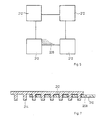
- Fig. 1 eine Seitenansicht eines ersten Beispiels des Geräteträgers, wobei die Auflagefläche im abgesenkten Zustand und (mit strichpunktierten Linien) im angehobenen und an die Auflageplatte herangeschobenen Zustand gezeigt ist,
- Fig. 2 eine Draufsicht auf Fig. 1,
- Fig. 3 einen Schnitt nach der Linie III-III in Fig. 1,
- Fig. 4 zeigt einen Längsschnitt durch ein zweites Ausführungsbeispiel eines Geräteträgers;
- Fig. 5 zeigt eine schematische Draufsicht auf eine in ihren Abmessungen variable Platte;
- Fig. 6 zeigt eine vergrößerte Draufsicht auf Teile der variablen Platte; und
- Fig. 7 zeigt einen Schnitt gemäß der Linie VII-VII in Fig. 6
- 1 is a side view of a first example of the device carrier, the support surface being shown in the lowered state and (with dash-dotted lines) in the raised state and pushed up to the support plate,
- 2 is a plan view of FIG. 1,
- 3 shows a section along the line III-III in FIG. 1,
- Fig. 4 shows a longitudinal section through a second embodiment of an equipment carrier;
- 5 shows a schematic top view of a plate which is variable in its dimensions;
- Fig. 6 shows an enlarged plan view of parts of the variable plate; and
- FIG. 7 shows a section along the line VII-VII in FIG. 6
Eine vertikale Säule 1 weist an ihrem unteren Ende mit einer nur angedeuteten Befestigungsvorrichtung 2 zum Befestigen an einer Unterlage, beispielsweise einem Schreibtisch, auf. An ihrem oberen Ende weist die Säule 1 ein Stützteil 4 auf, auf dem in waagrechter Richtung, in Fig. 1 von links nach rechts, ein Schlitten 6 verschiebbar ist, auf dem eine Tragpatte 8 um eine senkrecht zur Zeichenebene der Fig. 1 verlaufende, waagrechte Achse neigbar ist. Das Stützteil 4 ist mittels der Säule 1 um eine vertikale Achse schwenkbar gelagert. Ein in Betriebsstellung der ganzen Vorrichtung von dem Stützteil 4 aus schräg nach vorne (in Fig. 1 schräg nach rechts) verlaufender Tragarm 10 ist mit seinem vorderen Ende mittels eines Gelenks 12 mit rechtwinklig zur Zeichenebene der Fig. 1 verlaufender Schwenkachse an einem Teil 14 befestigt. An seinem anderen Ende ist der Tragarm 10 mittels eines weiteren Gelenks 16, das parallel zum Gelenk 12 verläuft, mit einem weiteren Arm 18 schwenkbar verbunden. In der in Fig. 1 mit ausgezogenen Linien gezeigten Stellung ist der Tragarm 10 und der weitere Arm 18 relativ zu dem Stützteil 4 so weit nach rechts verschoben worden, daß das Stützteil der Schwenkbewegung des Tragarms 10 nach unten in die in Fig. 1 gezeigte Stellung keinen Widerstand entgegensetzt. Wird der Tragarm 10 nach oben in eine waagrechte Stellung verschwenkt, so kann er nach links ins Innere des Stützteils 4 eingeschoben werden, so daß der Tragarm 10 nicht nach unten schwenken kann, wobei in der am weitesten eingeschobenen Stellung der weitere Arm 18 am hinteren Ende des Stützteils 4 herausragt, wie dies mit strichpunktierten Linien dargestellt ist.A vertical column 1 has at its lower end with an
Der weitere Arm 18 und das Teil 14 sind durch einen druck- und zugfesten Lenker, der genauso lang ist wie der Abstand der Gelenke Gelenke 12 und 16 und der parallel zur Verbindungslinie der Gelenke 12 und 16 verläuft, miteinander verbunden. Dadurch bleibt das Teil 14 unabhängig von der jeweiligen Schwenkstellung des Tragarms 10 immer parallel zu sich selbst. Mit dem Teil 14 ist über ein drittes Gelenk 22, dessen Schwenkachse lotrecht und somit parallel zur Schwenkachse der gesamten Vorrichtung verläuft, die durch die Säule 1 bestimmt wird, ein Auflageteil 24 verbunden, das zum Auflegen einer Tastatur vorgesehen ist, die die Anzeige auf einem auf die Tragplatte 8 aufzustellenden Sichtgerät steuert. Durch die oben beschriebene Parallelführung wird die Auflagefläche 26 des Auflageteils 24 stets horizontal gehalten. Das dritte Gelenk 22 gestattet, ausgehend von der Fig. 1 gezeigten Stellung, in der die rechtwinklig zur Zeichenebene der Fig. 1 verlaufende Querrichtung der Tastatur parallel zu der ebenfalls rechtwinklig zur Zeichenebene der Fig. 1 verlaufende Vorderseite des Bildschirmgeräts verläuft, das Auflageteil 24 um etwa 45° nach links und um 45° nach rechts zu verschwenken. Andere Schwenkwinkel sind ebenfalls möglich.The
Der Tragarm ist aus einem Hohlprofil hergestellt , das im wesentlichen einen rechteckförmigen Querschnitt aufweist, der an zwei Schmalseiten nach einwärts gezogen ist, wo im Bereich des Stützteils 4 Gleitbeläge 30 eingreifen, um eine leichte Verschiebbarkeit sicherzustellen.The support arm is made of a hollow profile, which has a substantially rectangular cross section, which is pulled inward on two narrow sides, where 4
Normalerweise sitzt das Teil 24 bei nach unten geschwenktem Tragarm 10 auf einer Unterlage auf, nämlich auf der Oberseite z.B. eines Schreibtischs, auf dem die gesamte Vorrichtung montiert ist. Es besteht hedoch die Möglichkeit, die Absenkbewegung des Teils 24 zu beschränken; hierzu ist ein beweglicher Anschlag, beispielsweise eine Schraube, vorgesehen, die in geeigneter Weise zwischen zwei der relativ zueinander beweglichen Teile des Lenkerparallelogramms (Tragarm 10, Teil 14, weiterer Arm 18 und der obengenannte Lenker) wirkt, um die Bewegung dieser Teile relativ zueinander auf den gewünschten Wert zu begrenzen.Normally, the
Der Tragarm 10 und die übrigen Teile sind ausreichend stabil, um auch dann, wenn sich das Teil 24 nicht auf einer festen Unterlage abstützt, die Tastatur so stabil zu unterstützen, daß ein Auf- und Abfedern der Tastatur nicht stattfindet.The
Der Tragarn 10 besteht im Ausführungsbeispiel aus Leichtmetall; stattdessen kann auch ein geeigneter Kunststoff verwendet werden.The
Der Schlitten 6 ist nur soweit verschiebbar, daß der Schwerpunkt eines auf der Tragplatte 8 stehenden Bildschirmgeräts sich noch oberhalb der Tragsäule 1 befindet, so daß größere auf die Tragsäule wirkende Kippmomente, die durch das Bildschirmgerät hervorgerufen werden können, vermieden werden.The
Bei einer Ausführungsform der Erfindung ist die Platte 8 in dem Schlitten 6 um eine senkrechte Achse schwenkbar gelagert, uns zwar um einen begrenzten Winkel, beispielsweise +/- 45° gegenüber der Verschieberichtung des Schlittens 6. Die Begrenzung dieses Schwenkwinkels kann in bekannter Weise erfolgen, beispielweise dadurch, daß ein an der Tragplatte 8 nach unten abstehender Bolzen in eine kreissegmentförmige Aussparung eingreift, so daß an den Enden dieser Aussparung die Schwenkbewegung endet.In one embodiment of the invention, the
An dem Tragarm 10 ist ein Konzepthalter 200 vorgesehen, der aus einem Drahtbügel geformt ist, dessen rechtwinklig abgebogende Enden in Bohrungen des Tragarmes 10 eingesteckt sind. Das Konzeptblatt wird zwischen der Oberfläche des Armes 10 und dem federnden Drahtbügel des Konzepthalters eingeklemmt. Der Drahtbügel trägt nur wenige Millimeter auf der Oberfläche des Armes 10 auf, so daß er das Einschieben des Armes in den Querschnitt des Stützteiles 4 nicht behindert. Vgl. auch Fig. 4.A
Schließlich kann bei Ausführungsformen der Erfindung die Säule 1 in einzelne Ringe unterteilt sein, die einzeln abnehmbar sind. Dadurch kann die Höhe der Säule 1 je nach der Bauhöhe des auf die Platte 8 aufgestellten Gerätes so eingestellt werden, daß der Bildschirm stets in der dem Benutzer geeigneten Höhe ist. Durch diese Ausbildung der Säule erhält man eine sehr einfache und preisgünstige Höheneinstellung der Platte 8 und des ganzen Geräteträgers. Diese Art der Höheneinstellung der Geräteplatte 8 läßt sich auch bei Vorrichtungen verwirklichen, bei denen kein Tragarm 10 mit Auflageteil 24 vorgesehen ist.Finally, in embodiments of the invention, the column 1 can be divided into individual rings which can be removed individually. As a result, the height of the column 1 can be adjusted depending on the height of the device placed on the
Die Säule kann einen hohlen Kern aufweisen, der aus ineinander teleskopartig verschiebbaren Rohren besteht. Die Rohre sind in diesem Falle von den Abstandsringen umgeben, die bei Bedarf herausgenommen oder hinzugefügt werden. Die einzelnen Ringe können bneispielsweise aus halbkreisförmigen Ringsegmenten bestehen, die nach dem Einfügen in die Säule 1 zu einem geschlossenen Ring zugesammengefügt und so befestigt werden. Anstelle der Ringe können jedoch auch u-förmige Abstandsstücke verwendet werden, die auf den Kern der Säulen 1 aufgeschoben werden und in dieser Lage befestigt werden.The column can have a hollow core which consists of tubes which can be telescoped into one another. In this case, the tubes are surrounded by the spacer rings, which can be removed or added if necessary. The individual rings can, for example, consist of semicircular ring segments which, after being inserted into the column 1, are joined to form a closed ring and are thus fastened. Instead of the rings, however, u-shaped spacers can also be used, which are pushed onto the core of the columns 1 and fastened in this position.
Bei dem in Fig. 4 gezeigten zweiten Ausführungsbeispiel sind diejenigen Teile, die dem in den Fig. 1 bis 3 gezeigten ersten Ausführungsbeispiel entsprechen, mit einem um 100 höheren Bezugszeichen bezeichnet. Nicht alle diese Teile sind in der nachfolgenden Beschreibung erwähnt. Der Schlitten 106 ist auf dem Stützteil 104 verschiebbar geführt. Hierzu ragt ein Bolzen 60 mit Gewinde durch ein Langloch 62 im Stützteil 104 hindurch. Am unteren Ende des Bolzens 60 ist eine im Beispiel dreieckige Platte 64 angeordnet, und auf den Bolzen 60 ist unter Zwischenschaltung einer Tellerfeder 61 eine Mutter 63 aufgeschraubt, die den Schlitten 106 unverlierbar am Stützteil 104 hält und gleichzeitig am Schlitten 106 ein Schwenkteil 66 drehbar befestigt, an dem ein Stab 68 befestigt ist, durch den es verdreht werden kann. Der Schlitten 106 hat zwei Verstärkungszonen 70, von denen in Fig. 4 nur eine sichtbar ist. Die Verstärkungszonen 70 weisen Lagerbohrungen 71 auf, die einen Schwenkkopf 72 um eine waagrechte Achse schwenkbar lagern, an dem die Platte 108 befestigt ist. Die Platte 64 bildet wegen ihrer eckigen Form und wegen der begrenzten Breite des Innenraums des Stützteils 104 rechtwinklig zur Zeicheneben der Fig. 4 einen Anschlag für die Schwenkbewegung des Schlittens um die senkrechte Achse. Der Schwenkkopf 72 ist somit in Längsrichtung des Langlochs 62 verschiebbar, um eine in der Lage veränderbare vertikale Achse begrenzt drehbar und außerdem um eine waagrechte Achse verschwenkbar.In the second exemplary embodiment shown in FIG. 4, those parts which correspond to the first exemplary embodiment shown in FIGS. 1 to 3 are denoted by a reference symbol which is 100 higher. Not all of these parts are mentioned in the description below. The
Der Schlitten 106 hat einen waagrecht verlaufenden Schlitz 92, und der Schwenkkopf 72 hat einen schräg zur Horizontalebene verlaufenden Schlitz 93, durch die der Stab 68, der geringfügig dünner ist als die Breite der Schlitze, hindurch geht. Wird der Stab 68 seitlich in den Schlitzen 92, 93 bewegt, so wird dadurch der Schwenkkopf 72 in den Lagerbohrungen 71 verschwenkt. Der Stab 68 kann um ungefähr 80° in der Horizontalebene verschwenkt werden. Dieser Bewegung entspricht eine Bewegung des Schwenkkopfes 72 um eine horizontale Achse (Lagerbohrungen 71) von +/- 10° bezüglich der Horizontalebene. Die Reibung zwischen dem Schlitten 106 und dem Stützteil 104 ist so gewählt, daß die oben genannte Bewegung des Stabs 68 normalerweise die Stellung des Schwenkkopfes bezüglich seiner vertikalen Schwenkachse nicht beeinflußt. Die Breite des Langlochs 62 ist wenig größer als die Dicke des Bolzens 60.The
Die Stange 68 bildet gemeinsam mit den Schlitzen 92 und 93 eine Antriebsvorrichtung für den Träger, die mindestens eine Kurve und eine formschlüssige Kopplung zwischen einer Betätigungsvorrichtung, im Ausführungsbeispiel nämlich der Stange 68, und dem Träger verwendet.The
Der ganze Geräteträger kann mittels einer Klemmvorrichtung 94 an einer Tischplatte befestigt werden. Die Säule 101 wird durch einen mit dem Stützteil 104 verbundenen Abschnitt 74 und durch einen an dessen unterem Ende lösbar befestigten ringförmigen Abschnitt 76 gebildet. Bei Bedarf können weitere ringförmige Abschnitte 76 zur passenden Einstellung der Länge der Säule 101 vorgesehen werden oder der gezeigte Abschnitt 76 entfernt werden.The entire device carrier can be attached to a table top by means of a
Damit die Auflagefläche 126 des Auflageteils 124 stets zu sich selbst parallel bleibt, ist das Teil 114 durch einen Lenker 80 mit dem weiteren Arm 118 verbunden. Der Abstand der Gelenke 112 und 82 einerseits und 116 und 84 andererseits ist gleich groß, und der Abstand zwischen den Gelenken 82 und 84 ist gleich groß wie der Abstand zwischen den Gelenken 112 und 116. Am Gelenk 116 ist auch das eine Ende einer als Zugfeder arbeitenden Gasfeder 90 schwenkbar befestigt, deren anderes Ende an dem Lenker 80 schwenkbar befestigt ist. Die Gasfeder 90 kann beim Ausziehen des Tragarms 10 in Fig. 4 nach links das Absenken des Auflageteils 124 nicht verhindern, verlangsamt aber das Absenken. Die Gasfeder bewirkt beim Anheben des Auflageteils 124 von Hand eine Gewichtsentlastung. Die Gasfeder weist einen in einem Zylinder abgedichtet gleitenden Kolben auf. Ein Vorteil gegenüber einer mechanischen Feder, z.B. einer Schraubenfeder, liegt in der genaueren Einhaltung vorgeschriebener Eigenschaften und der größeren Konstanz der Federeigenschaften.So that the
Auf der Oberseite des Tragarms 10 und 110 ist ein als flacher Drahtbügel ausgebildeter Konzepthalter 200 angeordnet, der federnd an dem Tragarm anliegt. Wenn der Tragarm schräg geneigt verläuft, kann eine mit dem Konzepthalter festgeklemmte Textvorlage bequem gelesen werden.A
Der ganze Geräteträger kann aus Metall hergestellt sein, ist aber bevorzugt hauptsächlich aus Kunststoff hergestellt. Die Schiebeführung des Tragarms in dem Stützteil kann in einer vom Beispiel abweichenden Weise erfolgen.The entire device carrier can be made of metal, but is preferably mainly made of plastic. The Sliding guidance of the support arm in the support part can take place in a different way from the example.
Fig. 5 zeigt eine Ausführungsform der auf dem Schwenkkopf befestigten Platte 108, die in ihrer Größe in beiden Richtungen veränderbar ist. Hierzu ist am Schwenkkopf eine Lochplatte 208 befestigt, die in regelmäßiger Anordnung eine Vielzahl von Aussparungen, im Beispiel durchgehende Löcher 210, trägt. Auf der Lochplatte 208 sind vier Auflageplatten 212, die an ihrer Unterseite in die Löcher 210 passende Vorsprünge 214 tragen, in der gewünschten Lage so aufgesetzt, daß Vorsprünge 214 in Löcher 210 eingreifen. Di Vorsprünge passen so genau in die Löcher, daß eine weitere Befestigung nicht nötig ist. Stattdessen ist es auch möglich, an den Auflageplatten statt der Vorsprünge nur eine oder zwei (oder auch mehr) Bohrungen anzubringen und die Auflageplatten mit der Lochplatte in der gewünschten Stellung durch Schraubverbindungen zu verbinden.FIG. 5 shows an embodiment of the
Bei den oben beschriebenen Ausführungsformen ist das auf dem Geräteträger anzuordnende Gerät, z.B. ein Kathodenstrahl-Sichtgerät, auf der Tragplatte 8, 108 bzw. den Platten 208, 212 angeordnet. Diese Tragplatte bildet dabei somit den eingangs genannten Träger. Ein derartiges Gerät kann jedoch auch unmittelbar auf dem Schwenkkopf 72 der Fig. 4 befestigt werden; in einem derartigen Fall bildet dieser Schwenkkopf den eingangs genannten, um ein vertikale Achse drehbar gelagerten Träger.In the embodiments described above, the device to be placed on the equipment carrier, e.g. a cathode ray viewer, arranged on the
Die Bezugszeichen in den Patentansprüchen sind keine Beschränkung, sondern sie sollen das Verständnis erleichtern.The reference symbols in the claims are not restricted, but are intended to facilitate understanding.
Claims (12)
Applications Claiming Priority (2)
| Application Number | Priority Date | Filing Date | Title |
|---|---|---|---|
| DE8703224U | 1987-03-03 | ||
| DE8703224U DE8703224U1 (en) | 1987-03-03 | 1987-03-03 |
Publications (2)
| Publication Number | Publication Date |
|---|---|
| EP0281093A2 true EP0281093A2 (en) | 1988-09-07 |
| EP0281093A3 EP0281093A3 (en) | 1989-06-14 |
Family
ID=6805423
Family Applications (1)
| Application Number | Title | Priority Date | Filing Date |
|---|---|---|---|
| EP88103149A Withdrawn EP0281093A3 (en) | 1987-03-03 | 1988-03-02 | Support for an apparatus |
Country Status (2)
| Country | Link |
|---|---|
| EP (1) | EP0281093A3 (en) |
| DE (1) | DE8703224U1 (en) |
Families Citing this family (4)
| Publication number | Priority date | Publication date | Assignee | Title |
|---|---|---|---|---|
| DE8703224U1 (en) * | 1987-03-03 | 1987-06-19 | Horn, Hans-Dieter, 7062 Rudersberg, De | |
| DE3820749C1 (en) * | 1988-06-18 | 1989-09-21 | Guenther 2300 Kiel De Krueger | Equipment support, in particular for the display unit and the keyboard of a data processing system |
| DE3933023A1 (en) * | 1989-10-01 | 1991-04-11 | Horst Haseke | Pivoted arm support for desk-top computers - allows units to be supported clear of surface of desk |
| DE4214341A1 (en) * | 1992-05-09 | 1993-11-11 | Ivan Mallinowski | Computer housing with adjustable monitor and keyboard holders - has computer mounted on plinth and supports spherically dished mounting plate on two adjustable pillars |
Citations (6)
| Publication number | Priority date | Publication date | Assignee | Title |
|---|---|---|---|---|
| EP0096373A1 (en) * | 1982-06-07 | 1983-12-21 | Haworth, Inc. | Adjustable support for CRT keyboard |
| DE8512337U1 (en) * | 1985-04-23 | 1985-06-27 | Haseke GmbH & Co KG, 4952 Porta Westfalica | Equipment carrier, in particular monitor carrier, with an inclinable device mounting plate |
| GB2154442A (en) * | 1984-02-21 | 1985-09-11 | Reginald John Spratling | Support unit |
| US4644875A (en) * | 1985-03-22 | 1987-02-24 | Weber-Knapp Company | Adjustable keyboard supporting mechanism |
| DE8703224U1 (en) * | 1987-03-03 | 1987-06-19 | Horn, Hans-Dieter, 7062 Rudersberg, De | |
| DE3614718C1 (en) * | 1986-04-30 | 1987-07-16 | Guenther Krueger | Device for receiving a data display device and a keyboard connected to it |
-
1987
- 1987-03-03 DE DE8703224U patent/DE8703224U1/de not_active Expired
-
1988
- 1988-03-02 EP EP88103149A patent/EP0281093A3/en not_active Withdrawn
Patent Citations (7)
| Publication number | Priority date | Publication date | Assignee | Title |
|---|---|---|---|---|
| EP0096373A1 (en) * | 1982-06-07 | 1983-12-21 | Haworth, Inc. | Adjustable support for CRT keyboard |
| GB2154442A (en) * | 1984-02-21 | 1985-09-11 | Reginald John Spratling | Support unit |
| US4644875A (en) * | 1985-03-22 | 1987-02-24 | Weber-Knapp Company | Adjustable keyboard supporting mechanism |
| DE8512337U1 (en) * | 1985-04-23 | 1985-06-27 | Haseke GmbH & Co KG, 4952 Porta Westfalica | Equipment carrier, in particular monitor carrier, with an inclinable device mounting plate |
| DE3614718C1 (en) * | 1986-04-30 | 1987-07-16 | Guenther Krueger | Device for receiving a data display device and a keyboard connected to it |
| EP0243945A2 (en) * | 1986-04-30 | 1987-11-04 | Günther Krüger | Supporting device for a computer terminal and a connected keyboard |
| DE8703224U1 (en) * | 1987-03-03 | 1987-06-19 | Horn, Hans-Dieter, 7062 Rudersberg, De |
Also Published As
| Publication number | Publication date |
|---|---|
| DE8703224U1 (en) | 1987-06-19 |
| EP0281093A3 (en) | 1989-06-14 |
Similar Documents
| Publication | Publication Date | Title |
|---|---|---|
| DE3036852C2 (en) | Device for setting up a data display device on a work surface | |
| DE2847135C3 (en) | Stand for an information display unit having a box-shaped housing | |
| EP2260229B1 (en) | Height-adjustable equipment stand | |
| EP0172320A1 (en) | Pivoting arm | |
| DE202018102954U1 (en) | Chin Up | |
| EP0065036B1 (en) | Table with adjustable top | |
| DE3840893C2 (en) | ||
| EP0281093A2 (en) | Support for an apparatus | |
| WO1984003573A1 (en) | Support installation for a keyboard connected to a data processing apparatus | |
| EP0113851B1 (en) | Support for a data display | |
| EP1944112B1 (en) | Circular saw bench | |
| DE8114991U1 (en) | WORK TABLE | |
| EP0280096B1 (en) | Supporting arrangement for a video display unit | |
| EP0482416A1 (en) | Furniture, especially a table | |
| DE2629727C3 (en) | Can be raised and lowered | |
| EP0145018A2 (en) | Blackboard | |
| DE10260587A1 (en) | Flipchart is guided on fixed guide elements of stand legs, and has a fixing mechanism which is formed of a clamp | |
| EP0045925A1 (en) | Sitting furniture, particularly swiveling office chair | |
| DE19511176C2 (en) | Device for adjusting the height and / or inclination of the table top of a table | |
| EP0826498B1 (en) | Pad printing machine | |
| DE2352159B2 (en) | Lifting device for automobiles | |
| DE3826534A1 (en) | Reading device for books | |
| DE19942817A1 (en) | Device for supporting fish rods | |
| DE2843438A1 (en) | Adhesively coating foam polystyrene thermally insulating plates - using appts. with dispensing hopper and roller frame pivotally mounted at opposite ends of hopper | |
| DE2834474B2 (en) | Device for storing instruments |
Legal Events
| Date | Code | Title | Description |
|---|---|---|---|
| PUAI | Public reference made under article 153(3) epc to a published international application that has entered the european phase |
Free format text: ORIGINAL CODE: 0009012 |
|
| AK | Designated contracting states |
Kind code of ref document: A2 Designated state(s): CH ES FR GB LI NL SE |
|
| PUAL | Search report despatched |
Free format text: ORIGINAL CODE: 0009013 |
|
| AK | Designated contracting states |
Kind code of ref document: A3 Designated state(s): CH ES FR GB LI NL SE |
|
| STAA | Information on the status of an ep patent application or granted ep patent |
Free format text: STATUS: THE APPLICATION IS DEEMED TO BE WITHDRAWN |
|
| 18D | Application deemed to be withdrawn |
Effective date: 19891215 |