EP0280193B1 - Lip structure for a stator in a dynamo-electric machine - Google Patents
Lip structure for a stator in a dynamo-electric machine Download PDFInfo
- Publication number
- EP0280193B1 EP0280193B1 EP88102368A EP88102368A EP0280193B1 EP 0280193 B1 EP0280193 B1 EP 0280193B1 EP 88102368 A EP88102368 A EP 88102368A EP 88102368 A EP88102368 A EP 88102368A EP 0280193 B1 EP0280193 B1 EP 0280193B1
- Authority
- EP
- European Patent Office
- Prior art keywords
- stator
- teeth
- lip
- slope angle
- degrees
- Prior art date
- Legal status (The legal status is an assumption and is not a legal conclusion. Google has not performed a legal analysis and makes no representation as to the accuracy of the status listed.)
- Revoked
Links
Images


Classifications
-
- H—ELECTRICITY
- H02—GENERATION; CONVERSION OR DISTRIBUTION OF ELECTRIC POWER
- H02K—DYNAMO-ELECTRIC MACHINES
- H02K1/00—Details of the magnetic circuit
- H02K1/06—Details of the magnetic circuit characterised by the shape, form or construction
- H02K1/12—Stationary parts of the magnetic circuit
-
- H—ELECTRICITY
- H02—GENERATION; CONVERSION OR DISTRIBUTION OF ELECTRIC POWER
- H02K—DYNAMO-ELECTRIC MACHINES
- H02K1/00—Details of the magnetic circuit
- H02K1/06—Details of the magnetic circuit characterised by the shape, form or construction
- H02K1/12—Stationary parts of the magnetic circuit
- H02K1/16—Stator cores with slots for windings
- H02K1/165—Shape, form or location of the slots
Definitions
- the present invention relates generally to stator constructions for dynamo-electric machines, and more particularly to a laminated stator comprised of a stack of plate laminations, wherein each of the laminations has a number of teeth extending radially from an inner bore opening, the teeth including lip parts to retain a stator winding with a closure wedge embedded in slots formed between adjacent teeth.
- Laminated stators for dynamo-electric machines are known generally from, for example, U.S. Patent 3,469,136 (September 23, 1969).
- the machine stator is comprised of a number of annular plate laminations of ferromagnetic material, stacked face-to-face with one another.
- Each plate has a circular inner opening to form a stator bore when the plates are stacked, and a number of equally circumferentially spaced slot openings extending radially from the circumference of the inner opening to form a number of teeth between which one or more stator windings are to be embedded.
- the winding slots in each plate together form a number of stator winding slots or recesses which extend generally parallel to the axis of the stator bore and a certain depth radially outward from the bore.
- One or more stator windings are then wound through selected ones of the slots between adjacent teeth, according to the number of poles desired for the machine.
- a slot insulator or liner Prior to inserting the winding conductors, a slot insulator or liner is usually inserted to extend axially along each slot in contact with the lamination material, to prevent arcing or short-circuiting between the winding conductors and the ferromagnetic material, of which the laminations are made.
- Each winding conductor is then inserted through mouth openings formed between adjacent teeth to enter the slot and, when all conductors of the winding or windings associated with the slot are in place, a closure wedge is inserted into the mouth slot, and lip parts of adjacent teeth which project into the mouth of the slot retain the wedge in place.
- U.S. Patent 4,486,506 December 4, 1984.
- An object of the invention is to ensure that the stator winding or windings are contained in the slot opening and to provide a lip structure which will minimize local flux saturation where a lip part is joined to a main body part of a stator tooth.
- a lamination for use in a laminated stator of a dynamo-electric machine includes a flat annular plate of ferromagnetic material with a generally circular inner opening to form a stator bore when like ones of the plate are stacked face to face.
- the plate has a number of uniformly circumferentially spaced slot openings extending from the circumference of the inner opening to form a number of teeth, the distal ends of which together define the circumference of the inner opening in the plate.
- Each of the teeth has a main body part and a pair of lip parts at its distal end, with each lip part projecting circumferentially into the mouth of a respective slot opening adjacent the tooth.
- Each lip part has an edge projecting from the main body part of the tooth to retain a stator winding and closure wedge when inserted in a slot opening adjacent the tooth, said edge being inclined to define a slope angle with respect to a line perpendicular to the center line of the slot opening into which the lip part projects.
- the slope angle for the lip parts is functionally related to the width of the teeth by varying in inverse relation of the width of the main body parts of said teeth.
- a dynamo-electric machine includes a generally cylindrical casing, a stator fixed in the casing and including a stack of plate laminations as claimed and having a cylindrical bore, a stator winding embedded in stator slots which extend radially outward from the circumference of the bore and generally parallel to the bore axis, a number of wedges each for containing the stator winding within the slots wherein the wedges are seated against lip parts of stator teeth adjacent the slots, and a rotor supported by the casing in the bore for rotational movement about the bore axis.
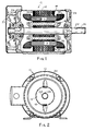
- Fig. 1 shows a side view, in section, of a dynamo electric machine 10, in which the present invention may be embodied.
- a front view of the machine 10 is shown in Fig. 2.
- the machine 10 includes a generally cylindrical outer casing 12, and a generally cylindrical stator 14 fixed coaxially within the outer casing 12 and having a coaxial stator bore 16.
- a rotor 18 is supported by suitable bearings 20a, 20b at the front and back of casing 12, to extend axially within the stator bore 16 and for rotational movement about the bore axis.
- a shaft part 22 of the rotor 18 extends axially from a front end shield 24 of the machine 10, and has a key 26 projecting radially outward from a recess cut axially a certain distance from the front of the shaft part 22. Key 26 serves to lock the shaft part 22 into a corresponding key way cut in a load member (not shown) e.g. a fan, to which rotational motive power is to be supplied by the machine 10.
- a load member not shown
- a back end shield 28 (Fig. 1) together with the casing 12 and the front end shield 24 serve to contain and protect the stator 14, rotor 18 and associated conductive windings.
- a machine cooling fan 30 is mounted on a rotor stub part 32 which extends outside the back end shield 28, and directs an air current flow over the casing.
- the stator 14 is comprised of a stack of plate laminations 34 of ferromagnetic material.
- the laminations 34 are stacked face-to-face and are suitably adhered to one another by means well known in the art. Slots which extend over the axial length of the stator 14 a certain radial depth from the stator bore 16, accommodate one or more stator windings, the end turns 36 of which are shown in Fig. 1. Details of the individual plate laminations 34 are given below in connection with Figs. 3 and 4.
- a plate lamination 34 in annular form includes an annular yoke portion 38 which extends from a circular outer periphery of the lamination 34 to a circumferential line 40 which defines the depths of a number of equally circumferentially spaced slot openings 42 from the circumference 44 of an inner opening in the lamination 34.
- the inner circumference 44 defines the diameter of the stator bore 16
- the individual slot openings 42 of the stacked laminations 34 are circumferentially aligned to form the axially extending slots within which the stator windings are embedded in the machine 10 of Fig. 1.
- the stator winding is inserted in the slot openings 42 through mouths 46 of the slot openings which mouths are wide enough to receive individual conductors of the stator winding.
- a number of teeth 48 are formed between adjacent slot openings 42, the teeth having main body parts 50 and lip parts 52 at distal ends of the teeth.
- Each lip part 52 projects circumferentially into the mouth 46 of a respective slot opening 42 adjacent the associated tooth 48.
- each lip part 52 has in inclined edge 54 projecting from the main body part 50 of an associated tooth.
- the edges 54 serve to retain a stator winding or windings and a closure wedge when the winding conductors are inserted in the slot opening 42 into which the edge 54 of the lip part 52 projects.
- Fig. 7 shows one example in which two stator windings 56, 58 are contained in each slot opening 42 by way of an insulated wedge 60 and an insulating winding separator 62.
- An insulative liner 64 is also placed within the slot opening 42 after the laminations 34 are stacked to define the winding slots in the machine stator 14 (Fig. 1).
- Each of the teeth 48 has a certain width T1 about a radial center line through its main body part 50, as shown in FIG. 4.
- the inclined edges 54 of the lip parts 52 define a slope angle ⁇ with respect to a line perpendicular to a center line of the slot opening 42 into which the lip part projects a distance P (see Fig. 4).
- the distance P is measured from the beginning of curvature point R to a line parallel to the slot center line, such line passing through the furthermost point M of the tooth tip toward the center line of the slot.
- the slope angle ⁇ for the lip part edges is functionally related to the width T1 of the teeth 48.
- the slope angle ⁇ varies in inverse relation to the width T1 of the main body parts 50 of the teeth 48 for a given circumferential opening for the mouths 46 of the opening 42.
- Such a relationship between the slope angle ⁇ and the teeth width T1 ensures that the stator winding or windings contained in the slot openings 42 and the closure wedge 60 will be firmly held in place by the lip parts 52 of adjacent teeth, while the machine 10 is operating. Specifically, it will be seen in Fig.
- a slope angle ⁇ in the range of from 15 degrees to 22 degrees provides superior seating reliability for stator winding wedges 60, particularly when the lip parts 52 project into the slot openings by only about 0.71 mm. as may occur if a width T1 of 6.9 mm. is chosen for the width of the teeth 48, as shown in Fig. 4.
- the slope angle ⁇ is preferably about 17.5 degrees.
- the slope angled ⁇ may then be selected to be greater than the 22.5 degree standard, so as to avoid saturation of the lamination material at the point where the edges 54 of the lip parts meet the main body parts 50 of the teeth 48.
- a plate lamination 34' with stator teeth 48' having lip parts 52' of such proportions is shown in Figs. 5 and 6.
- the width T1for the teeth 48' in the Figs. 5 and 6 embodiment is about 6.1 mm.
- the angle ⁇ for the lip parts 52' can be in the range of from 23 degrees to 30 degrees, preferably 27.5 degrees. Likewise such angles could be used for a lip width in the range of 1.1 mm. to 2.1 mm.
- This application 03 GP 6093 is being filed on the same day as commonly assigned applications 03 GP 6077 - BASE ASSEMBLY FOR DYNAMO-ELECTRIC MACHINE in the name of Robert L. Sieber, S. N. 019 823 ; 03 GP 6082 - DYNAMO-ELECTRIC MACHINE LAMINATION CONSTRUCTION in the name of Thomas W. Neumann, S. N. 020 297 ; and 03 GP 6073 - CLOSED SLOT ROTOR CONSTRUCTION in the names of Deepakkumar J. briefly et al., S. N. 020 299 . The entire disclosures of all of these three (3) other applications are specifically incorporated herein by reference.
Description
- The present invention relates generally to stator constructions for dynamo-electric machines, and more particularly to a laminated stator comprised of a stack of plate laminations, wherein each of the laminations has a number of teeth extending radially from an inner bore opening, the teeth including lip parts to retain a stator winding with a closure wedge embedded in slots formed between adjacent teeth.
- Laminated stators for dynamo-electric machines are known generally from, for example, U.S. Patent 3,469,136 (September 23, 1969). Basically, the machine stator is comprised of a number of annular plate laminations of ferromagnetic material, stacked face-to-face with one another. Each plate has a circular inner opening to form a stator bore when the plates are stacked, and a number of equally circumferentially spaced slot openings extending radially from the circumference of the inner opening to form a number of teeth between which one or more stator windings are to be embedded.
- When the plate laminations are stacked in proper alignment to form the stator, the winding slots in each plate together form a number of stator winding slots or recesses which extend generally parallel to the axis of the stator bore and a certain depth radially outward from the bore. One or more stator windings are then wound through selected ones of the slots between adjacent teeth, according to the number of poles desired for the machine. Prior to inserting the winding conductors, a slot insulator or liner is usually inserted to extend axially along each slot in contact with the lamination material, to prevent arcing or short-circuiting between the winding conductors and the ferromagnetic material, of which the laminations are made.
- Each winding conductor is then inserted through mouth openings formed between adjacent teeth to enter the slot and, when all conductors of the winding or windings associated with the slot are in place, a closure wedge is inserted into the mouth slot, and lip parts of adjacent teeth which project into the mouth of the slot retain the wedge in place. See, for example, U.S. Patent 4,486,506 (December 4, 1984). Until now, it has been the practice to incline the edge of each lip part which edge faces the closure wedge, at an angle of 22.5 degrees relative to a line perpendicular to the slot center line. It has been found, however, that for a given mouth opening between confronting lip parts of adjacent teeth, the 22.5 degree inclination angle may not be sufficient to seat the closure wedges firmly in place with the result that the wedge and possibly some of the winding conductors protrude from the slot mouth and contact the machine rotor with damaging results.
- An object of the invention is to ensure that the stator winding or windings are contained in the slot opening and to provide a lip structure which will minimize local flux saturation where a lip part is joined to a main body part of a stator tooth.
- According to the invention, as claimed, a lamination for use in a laminated stator of a dynamo-electric machine, includes a flat annular plate of ferromagnetic material with a generally circular inner opening to form a stator bore when like ones of the plate are stacked face to face. The plate has a number of uniformly circumferentially spaced slot openings extending from the circumference of the inner opening to form a number of teeth, the distal ends of which together define the circumference of the inner opening in the plate. Each of the teeth has a main body part and a pair of lip parts at its distal end, with each lip part projecting circumferentially into the mouth of a respective slot opening adjacent the tooth. Each lip part has an edge projecting from the main body part of the tooth to retain a stator winding and closure wedge when inserted in a slot opening adjacent the tooth, said edge being inclined to define a slope angle with respect to a line perpendicular to the center line of the slot opening into which the lip part projects. The slope angle for the lip parts is functionally related to the width of the teeth by varying in inverse relation of the width of the main body parts of said teeth.
- According to another aspect of the invention, a dynamo-electric machine includes a generally cylindrical casing, a stator fixed in the casing and including a stack of plate laminations as claimed and having a cylindrical bore, a stator winding embedded in stator slots which extend radially outward from the circumference of the bore and generally parallel to the bore axis, a number of wedges each for containing the stator winding within the slots wherein the wedges are seated against lip parts of stator teeth adjacent the slots, and a rotor supported by the casing in the bore for rotational movement about the bore axis.
- It has been found that by making the lip part inclination or slope angle a function of the stator tooth width for a given mouth opening, the closure wedges, winding conductors, and slot insulators will remain securely in place within the stator slots by the seating action of the lip parts.
- The various features of novelty which characterize the invention are pointed out with particularity in the claims annexed to and forming a part of the present disclosure. For a better understanding of the invention, its operation advantages and specific objects attained by its use, reference should be had to the accompanying drawing and descriptive matter in which there are illustrated and described preferred embodiments of the invention.
-
- Fig. 1 is a side view, partly in section, of a dynamo-electric machine in which the present invention may be embodied;
- Fig. 2 is a front view of the machine in Fig. 1;
- Fig. 3 is a plan view of a plate lamination for forming a stator in the machine of Figs. 1 & 2, showing teeth with lip parts according to the invention;
- Fig. 4 is an enlarged view of a part of the lamination in Fig. 3;
- Fig. 5 is a plan view of another plate lamination for forming a stator in the machine of Figs. 1 and 2, showing teeth with lip parts according to the invention;
- Fig. 6 is an enlarged view of a part of the lamination in Fig. 5; and
- Fig. 7 is a view of a slot opening in part of a lamination, showing an insulating wedge seated against lip parts of adjacent teeth according to the invention.
- Fig. 1 shows a side view, in section, of a dynamo
electric machine 10, in which the present invention may be embodied. A front view of themachine 10 is shown in Fig. 2. - Basically, the
machine 10 includes a generally cylindricalouter casing 12, and a generallycylindrical stator 14 fixed coaxially within theouter casing 12 and having acoaxial stator bore 16. Arotor 18 is supported by suitable bearings 20a, 20b at the front and back ofcasing 12, to extend axially within thestator bore 16 and for rotational movement about the bore axis. In the particular example shown, ashaft part 22 of therotor 18 extends axially from afront end shield 24 of themachine 10, and has a key 26 projecting radially outward from a recess cut axially a certain distance from the front of theshaft part 22.Key 26 serves to lock theshaft part 22 into a corresponding key way cut in a load member (not shown) e.g. a fan, to which rotational motive power is to be supplied by themachine 10. - A back end shield 28 (Fig. 1) together with the
casing 12 and thefront end shield 24 serve to contain and protect thestator 14,rotor 18 and associated conductive windings. In the example shown amachine cooling fan 30 is mounted on a rotor stub part 32 which extends outside theback end shield 28, and directs an air current flow over the casing. - As shown in Fig. 1, the
stator 14 is comprised of a stack ofplate laminations 34 of ferromagnetic material. Thelaminations 34 are stacked face-to-face and are suitably adhered to one another by means well known in the art. Slots which extend over the axial length of the stator 14 a certain radial depth from thestator bore 16, accommodate one or more stator windings, the end turns 36 of which are shown in Fig. 1. Details of theindividual plate laminations 34 are given below in connection with Figs. 3 and 4. - In Fig. 3, a
plate lamination 34 in annular form includes anannular yoke portion 38 which extends from a circular outer periphery of thelamination 34 to acircumferential line 40 which defines the depths of a number of equally circumferentially spacedslot openings 42 from thecircumference 44 of an inner opening in thelamination 34. It will be understood that when thelamination 34 is stacked face-to-face with other like laminations, theinner circumference 44 defines the diameter of thestator bore 16, and theindividual slot openings 42 of thestacked laminations 34 are circumferentially aligned to form the axially extending slots within which the stator windings are embedded in themachine 10 of Fig. 1. The stator winding is inserted in theslot openings 42 throughmouths 46 of the slot openings which mouths are wide enough to receive individual conductors of the stator winding. - A number of
teeth 48 are formed betweenadjacent slot openings 42, the teeth havingmain body parts 50 andlip parts 52 at distal ends of the teeth. Eachlip part 52 projects circumferentially into themouth 46 of a respective slot opening 42 adjacent the associatedtooth 48. - As shown in Fig. 4, each
lip part 52 has ininclined edge 54 projecting from themain body part 50 of an associated tooth. Theedges 54 serve to retain a stator winding or windings and a closure wedge when the winding conductors are inserted in the slot opening 42 into which theedge 54 of thelip part 52 projects. Fig. 7 shows one example in which twostator windings wedge 60 and an insulatingwinding separator 62. Aninsulative liner 64 is also placed within the slot opening 42 after thelaminations 34 are stacked to define the winding slots in the machine stator 14 (Fig. 1). - Each of the
teeth 48 has a certain width T₁ about a radial center line through itsmain body part 50, as shown in FIG. 4. Moreover, theinclined edges 54 of thelip parts 52 define a slope angle α with respect to a line perpendicular to a center line of the slot opening 42 into which the lip part projects a distance P (see Fig. 4). The distance P is measured from the beginning of curvature point R to a line parallel to the slot center line, such line passing through the furthermost point M of the tooth tip toward the center line of the slot. - In accordance with the invention, the slope angle α for the lip part edges is functionally related to the width T₁ of the
teeth 48. Preferably, the slope angle α varies in inverse relation to the width T₁ of themain body parts 50 of theteeth 48 for a given circumferential opening for themouths 46 of theopening 42. Such a relationship between the slope angle α and the teeth width T₁ ensures that the stator winding or windings contained in theslot openings 42 and theclosure wedge 60 will be firmly held in place by thelip parts 52 of adjacent teeth, while themachine 10 is operating. Specifically, it will be seen in Fig. 7, that if a too steep slope angle were provided for the edges of thelip parts 52, thewedge 60 may become unseated and project out of themouth 46 of theslot opening 42. It will be understood that such dislocation of the wedge and possibly the stator winding would disturb the flux paths established through an air gap between the inner circumference of thestator 14 and the outer circumference of therotor 18 in themachine 10 of Fig. 1. Operating performance will then suffer and, if the wedge or stator winding advances through the air gap and crashes against the outer surface of therotor 18 while turning at high speed, irreparable damage can result. - It has been discovered that a slope angle α in the range of from 15 degrees to 22 degrees provides superior seating reliability for
stator winding wedges 60, particularly when thelip parts 52 project into the slot openings by only about 0.71 mm. as may occur if a width T₁ of 6.9 mm. is chosen for the width of theteeth 48, as shown in Fig. 4. - In such case, the slope angle α is preferably about 17.5 degrees.
- When the
lips part 52 project circumferentially into theslot openings 42 by greater amounts such as by about 1.125 mm. the slope angled α may then be selected to be greater than the 22.5 degree standard, so as to avoid saturation of the lamination material at the point where theedges 54 of the lip parts meet themain body parts 50 of theteeth 48. A plate lamination 34' with stator teeth 48' having lip parts 52' of such proportions is shown in Figs. 5 and 6. The width T₁for the teeth 48' in the Figs. 5 and 6 embodiment is about 6.1 mm. To avoid localized flux saturation, but still ensure proper seating of the stator winding wedges the angle α for the lip parts 52' can be in the range of from 23 degrees to 30 degrees, preferably 27.5 degrees. Likewise such angles could be used for a lip width in the range of 1.1 mm. to 2.1 mm. - This application 03 GP 6093 is being filed on the same day as commonly assigned applications 03 GP 6077 - BASE ASSEMBLY FOR DYNAMO-ELECTRIC MACHINE in the name of Robert L. Sieber, S. N. 019 823; 03 GP 6082 - DYNAMO-ELECTRIC MACHINE LAMINATION CONSTRUCTION in the name of Thomas W. Neumann, S. N. 020 297; and 03 GP 6073 - CLOSED SLOT ROTOR CONSTRUCTION in the names of Deepakkumar J. Gandhi et al., S. N. 020 299. The entire disclosures of all of these three (3) other applications are specifically incorporated herein by reference.
Claims (12)
- A lamination for use in a lamination stack forming a stator in a dynamo-electric machine, comprising:
a flat annular plate of ferro-magnetic material having a substantially continuous outer periphery, and a generally circular inner opening to form a stator bore in the machine stator when like ones of said annular plate are stacked face-to-face;
said plate having a number of uniformly circumferentially spaced slot openings (42) extending radially outward from a circumference of said inner opening to form a number of teeth (48) of predetermined width, wherein the mouths (46) of said slot openings (42) are sufficiently wide to receive a stator winding when inserted between said teeth and distal ends of said teeth together define the circumference of said inner opening;
each of said teeth (48) paving a main body part (50) extending radially from its distal end and a pair of lip parts (52) at the distal end wherein each lip part (52) projects circumferentially into the mouth (46) of a respective slot opening (42) adjacent the tooth (48);
each lip (52) having an edge (54) projecting from the main body part (50) of the tooth (48) for retaining the stator winding when inserted in the slot opening (42) adjacent the tooth, said inclined edge (54) sloping radially inward to define a slope angle (α) with respect to a line perpendicular to the center line of the slot opening (42) into which the lip part (52) projects;
characterized in that said slope angle (α) varies in inverse relation to the width of the main body parts (50) of said teeth (48). - The lamination according to Claim 1, wherein said slope angle (α) is in the range of from 15 degrees to 22 degrees.
- The lamination according to Claim 1, wherein said slope angle (α) is about 17.5 degrees.
- The lamination according to Claim 1, wherein each lip part (52) projects into the respective slot opening (42) about 0,71 mm. and said slope angle (α) is about 17.5 degrees.
- The lamination according to Claim 2, wherein each lip part (52) projects into the respective slot opening (42) about 0,71 mm., the width of said teeth (48) is about 6,9 mm., and said slope angle (α) is about 17,5 degrees.
- The lamination according to Claim 1, wherein said slope angle (α) is in the range of from 23 degrees to 30 degrees.
- The lamination according to Claim 1, wherein said slope angle (α) is about 27,5 degrees.
- The lamination according to Claims 1, wherein each lip part (52) projects into the respective slot opening about 1,125 mm.
- The lamination according to Claims 1, wherein each lip part (52) projects into the respective slot opening (42) about 1,125 mm and the width of said teeth is about 6,1 mm.
- The lamination according to Claim 6, wherein for a given width for said teeth (48), said slope angle (α) is selected to minimize saturation of said stator winding flux at points where the inclined edges (54) of the lip parts (52) intersect the main body part (50) of each tooth (48).
- The lamination according to Claim 1, wherein the width of said lip (52) is in the range of 1,1 mm to 2,1 mm and said slope angle (α) is about 27,5 degrees.
- The lamination of any one of claims 1 to 11, wherein said dynamo-electric machine comprises:
a generally cylindrical casing (12);
a stator (14) fixed in said casing and comprised of a stack of said plate laminations (34) of ferromagnetic material, said stator having a cylindrical bore (16);
a stator winding embedded in stator slots which extend radially outward from the circumference of said bore;
a number of wedges (60) each for containing the stator winding within corresponding ones of said slots, wherein said wedges (60) are seated against lip parts (52) of stator teeth (48) adjacent said slots, and
a rotor (18) supported by said casing (12) in said bore (16) for rotational movement about the bore axis, said rotor including conductive means for interacting with a magnetic field when said stator winding is energized by an outside electrical source.
Applications Claiming Priority (2)
| Application Number | Priority Date | Filing Date | Title |
|---|---|---|---|
| US07/019,811 US4780636A (en) | 1987-02-27 | 1987-02-27 | Lip structure for a stator in a dynamo-electric machine |
| US19811 | 1998-02-06 |
Publications (3)
| Publication Number | Publication Date |
|---|---|
| EP0280193A2 EP0280193A2 (en) | 1988-08-31 |
| EP0280193A3 EP0280193A3 (en) | 1990-01-10 |
| EP0280193B1 true EP0280193B1 (en) | 1993-11-10 |
Family
ID=21795162
Family Applications (1)
| Application Number | Title | Priority Date | Filing Date |
|---|---|---|---|
| EP88102368A Revoked EP0280193B1 (en) | 1987-02-27 | 1988-02-18 | Lip structure for a stator in a dynamo-electric machine |
Country Status (5)
| Country | Link |
|---|---|
| US (1) | US4780636A (en) |
| EP (1) | EP0280193B1 (en) |
| JP (1) | JPS6447240A (en) |
| KR (1) | KR0135768B1 (en) |
| DE (1) | DE3885477T2 (en) |
Families Citing this family (12)
| Publication number | Priority date | Publication date | Assignee | Title |
|---|---|---|---|---|
| US5289065A (en) * | 1993-04-05 | 1994-02-22 | Ford Motor Company | Zero air gap orbiting gear stepper motor |
| US6347527B1 (en) * | 1997-12-02 | 2002-02-19 | Louis J. Bailey | Integrated system for heating, cooling and heat recovery ventilation |
| JP3535012B2 (en) * | 1998-06-09 | 2004-06-07 | ミネベア株式会社 | Radial gap type small cylindrical rotating electric machine |
| JP3383251B2 (en) * | 1999-12-27 | 2003-03-04 | 三菱電機株式会社 | Vehicle alternator stator |
| JP4476111B2 (en) * | 2004-12-08 | 2010-06-09 | 三菱電機株式会社 | AC generator |
| JP5130777B2 (en) * | 2007-04-23 | 2013-01-30 | 株式会社豊田自動織機 | Stator |
| JP5424814B2 (en) * | 2009-05-21 | 2014-02-26 | 三菱電機株式会社 | Permanent magnet type rotating electric machine |
| JP6156679B2 (en) * | 2013-01-25 | 2017-07-05 | 株式会社デンソー | Rotating electric machine stator |
| CN103532267A (en) * | 2013-10-09 | 2014-01-22 | 中达电机股份有限公司 | Stator stamping structure for 2P electromotors |
| DE102016200081A1 (en) * | 2016-01-07 | 2017-07-13 | Continental Automotive Gmbh | Electric machine |
| KR20190068975A (en) * | 2017-12-11 | 2019-06-19 | 현대자동차주식회사 | Motor |
| JP7306040B2 (en) * | 2019-04-19 | 2023-07-11 | ニデック株式会社 | motor |
Family Cites Families (19)
| Publication number | Priority date | Publication date | Assignee | Title |
|---|---|---|---|---|
| US2610225A (en) * | 1948-12-20 | 1952-09-09 | Emerson Electric Mfg Co | Core construction for electrical equipment |
| US2700115A (en) * | 1950-10-10 | 1955-01-18 | Walt Inc De | Air-cooled electric motor |
| CH313455A (en) * | 1952-11-13 | 1956-04-15 | Cem Comp Electro Mec | Set of false rotors for machines for winding the stators of electric machines |
| US2701317A (en) * | 1953-11-18 | 1955-02-01 | Gen Electric | Dynamoelectric machine winding insulator |
| FR1169617A (en) * | 1955-12-30 | 1958-12-31 | Gen Motors Corp | Insulation for motor, especially for refrigerator motor |
| US3253171A (en) * | 1961-11-30 | 1966-05-24 | Smith Corp A O | Laminated structure binding means |
| US3229134A (en) * | 1962-01-25 | 1966-01-11 | Litton Industries Inc | Thermal variation compensation means and method |
| US3235762A (en) * | 1962-05-02 | 1966-02-15 | Gen Electric | Stator for use in alternating current induction motors |
| US3469136A (en) * | 1968-03-21 | 1969-09-23 | Lucas Industries Ltd | Laminated stators for dynamo electric machines |
| US3735169A (en) * | 1971-04-04 | 1973-05-22 | Gen Electric | Channel,shaped,laminated,high temperature slot wedge for dynamoelectric machines |
| JPS5341321B1 (en) * | 1971-07-30 | 1978-11-02 | ||
| US3827141A (en) * | 1972-05-17 | 1974-08-06 | Skf Ind Trading & Dev | Method of manufacturing an electric rotary machine |
| US3821846A (en) * | 1973-01-10 | 1974-07-02 | Smith Corp A | Method of manufacturing a motor stator assembly |
| US3909648A (en) * | 1973-07-27 | 1975-09-30 | Smith Corp A O | Electric motor having a winding insulating barrier and method of construction |
| US4241274A (en) * | 1978-05-10 | 1980-12-23 | General Electric Company | Dynamoelectric machine and stationary assembly therefor |
| FR2481017A1 (en) * | 1980-04-17 | 1981-10-23 | Ducellier & Cie | Stator for vehicle alternator - has twisted pole pieces increasing effective pole area and output power |
| JPS57101540A (en) * | 1980-12-11 | 1982-06-24 | Fanuc Ltd | Induction motor |
| US4486506A (en) * | 1981-10-16 | 1984-12-04 | Tokyo Shibaura Denki Kabushiki Kaisha | Solid insulator and electric equipment coil using the same |
| US4654552A (en) * | 1985-03-28 | 1987-03-31 | General Electric Company | Lanced strip and edgewise wound core |
-
1987
- 1987-02-27 US US07/019,811 patent/US4780636A/en not_active Expired - Lifetime
-
1988
- 1988-02-18 EP EP88102368A patent/EP0280193B1/en not_active Revoked
- 1988-02-18 DE DE3885477T patent/DE3885477T2/en not_active Revoked
- 1988-02-26 JP JP63042413A patent/JPS6447240A/en active Pending
- 1988-02-27 KR KR1019880002025A patent/KR0135768B1/en not_active IP Right Cessation
Also Published As
| Publication number | Publication date |
|---|---|
| US4780636A (en) | 1988-10-25 |
| EP0280193A2 (en) | 1988-08-31 |
| JPS6447240A (en) | 1989-02-21 |
| DE3885477D1 (en) | 1993-12-16 |
| DE3885477T2 (en) | 1994-06-16 |
| KR0135768B1 (en) | 1998-04-23 |
| EP0280193A3 (en) | 1990-01-10 |
| KR880010535A (en) | 1988-10-10 |
Similar Documents
| Publication | Publication Date | Title |
|---|---|---|
| EP0280194B1 (en) | Dynamo-electric machine lamination construction | |
| US6703741B1 (en) | Permanent magnet rotor portion for electric machines | |
| US4801832A (en) | Stator and rotor lamination construction for a dynamo-electric machine | |
| EP0872943B1 (en) | Permanent-magnet revolving electrodynamic machine with a concentrated stator winding | |
| EP0740397B1 (en) | Stator structure for rotary electric machine | |
| EP0280193B1 (en) | Lip structure for a stator in a dynamo-electric machine | |
| EP0160868A2 (en) | Brushless motor | |
| JP4291517B2 (en) | Improved permanent magnet / reluctance variable rotating electrical equipment | |
| JPH0132743B2 (en) | ||
| JPH0898481A (en) | Ac generator for vehicle | |
| JPH08251891A (en) | Hybrid exciting electric rotary machine | |
| JP2003510998A (en) | Permanent magnet rotor for electric machines | |
| EP0429729A1 (en) | Electric machines with ironcore disk armatures | |
| JPS6185045A (en) | Ac generator for vehicle | |
| EP0136584B1 (en) | Rotor for rotary machine | |
| JPH1118345A (en) | Stator of rotating electric machine | |
| JPH08251848A (en) | Rotor of permanent magnet type synchronous rotary machine | |
| JP2003134762A (en) | Electric rotating machine | |
| US2560560A (en) | Stator for universal electric motors | |
| JPH08107639A (en) | Rotor of permanent magnet type synchronous electric rotating machine | |
| US3427486A (en) | Dynamoelectric machines using ceramic permanent magnets | |
| US6252330B1 (en) | Dynamo-electric rotor with reduced magnetic flux leakage and with a structure permitting high efficiency assembly | |
| JP2960128B2 (en) | Reluctance rotating machine | |
| EP0157526A2 (en) | Reluctance rotary machine | |
| JPS61293142A (en) | High-speed synchronous rotary machine with rotor comprising permanent magnet for producing magnetic field vartical to diametrical direction |
Legal Events
| Date | Code | Title | Description |
|---|---|---|---|
| PUAI | Public reference made under article 153(3) epc to a published international application that has entered the european phase |
Free format text: ORIGINAL CODE: 0009012 |
|
| AK | Designated contracting states |
Kind code of ref document: A2 Designated state(s): DE FR GB IT NL SE |
|
| PUAL | Search report despatched |
Free format text: ORIGINAL CODE: 0009013 |
|
| AK | Designated contracting states |
Kind code of ref document: A3 Designated state(s): DE FR GB IT NL SE |
|
| 17P | Request for examination filed |
Effective date: 19900627 |
|
| 17Q | First examination report despatched |
Effective date: 19920527 |
|
| GRAA | (expected) grant |
Free format text: ORIGINAL CODE: 0009210 |
|
| AK | Designated contracting states |
Kind code of ref document: B1 Designated state(s): DE FR GB IT NL SE |
|
| REF | Corresponds to: |
Ref document number: 3885477 Country of ref document: DE Date of ref document: 19931216 |
|
| ET | Fr: translation filed | ||
| ITF | It: translation for a ep patent filed |
Owner name: SAIC BREVETTI S.R.L. |
|
| PLBI | Opposition filed |
Free format text: ORIGINAL CODE: 0009260 |
|
| 26 | Opposition filed |
Opponent name: DANFOSS A/S Effective date: 19940808 |
|
| NLR1 | Nl: opposition has been filed with the epo |
Opponent name: DANFOSS A/S |
|
| EAL | Se: european patent in force in sweden |
Ref document number: 88102368.3 |
|
| PLBF | Reply of patent proprietor to notice(s) of opposition |
Free format text: ORIGINAL CODE: EPIDOS OBSO |
|
| PGFP | Annual fee paid to national office [announced via postgrant information from national office to epo] |
Ref country code: FR Payment date: 19970115 Year of fee payment: 10 |
|
| PGFP | Annual fee paid to national office [announced via postgrant information from national office to epo] |
Ref country code: DE Payment date: 19970117 Year of fee payment: 10 |
|
| PGFP | Annual fee paid to national office [announced via postgrant information from national office to epo] |
Ref country code: GB Payment date: 19970127 Year of fee payment: 10 |
|
| RDAH | Patent revoked |
Free format text: ORIGINAL CODE: EPIDOS REVO |
|
| APAC | Appeal dossier modified |
Free format text: ORIGINAL CODE: EPIDOS NOAPO |
|
| APAE | Appeal reference modified |
Free format text: ORIGINAL CODE: EPIDOS REFNO |
|
| APAB | Appeal dossier modified |
Free format text: ORIGINAL CODE: EPIDOS NOAPE |
|
| APAC | Appeal dossier modified |
Free format text: ORIGINAL CODE: EPIDOS NOAPO |
|
| RDAG | Patent revoked |
Free format text: ORIGINAL CODE: 0009271 |
|
| STAA | Information on the status of an ep patent application or granted ep patent |
Free format text: STATUS: PATENT REVOKED |
|
| PGFP | Annual fee paid to national office [announced via postgrant information from national office to epo] |
Ref country code: SE Payment date: 19980120 Year of fee payment: 11 |
|
| PGFP | Annual fee paid to national office [announced via postgrant information from national office to epo] |
Ref country code: NL Payment date: 19980121 Year of fee payment: 11 |
|
| 27W | Patent revoked |
Effective date: 19971207 |
|
| GBPR | Gb: patent revoked under art. 102 of the ep convention designating the uk as contracting state |
Free format text: 971207 |
|
| NLR2 | Nl: decision of opposition | ||
| APAH | Appeal reference modified |
Free format text: ORIGINAL CODE: EPIDOSCREFNO |