EP0267528A2 - Digital data transmission system with adressable repeaters having fault localization devices - Google Patents
Digital data transmission system with adressable repeaters having fault localization devices Download PDFInfo
- Publication number
- EP0267528A2 EP0267528A2 EP19870116189 EP87116189A EP0267528A2 EP 0267528 A2 EP0267528 A2 EP 0267528A2 EP 19870116189 EP19870116189 EP 19870116189 EP 87116189 A EP87116189 A EP 87116189A EP 0267528 A2 EP0267528 A2 EP 0267528A2
- Authority
- EP
- European Patent Office
- Prior art keywords
- address
- locating device
- regenerator
- regenerators
- memory
- Prior art date
- Legal status (The legal status is an assumption and is not a legal conclusion. Google has not performed a legal analysis and makes no representation as to the accuracy of the status listed.)
- Granted
Links
Images
Classifications
-
- H—ELECTRICITY
- H04—ELECTRIC COMMUNICATION TECHNIQUE
- H04B—TRANSMISSION
- H04B17/00—Monitoring; Testing
- H04B17/40—Monitoring; Testing of relay systems
- H04B17/401—Monitoring; Testing of relay systems with selective localization
- H04B17/406—Monitoring; Testing of relay systems with selective localization using coded addresses
Definitions
- the invention relates to intermediate regenerators provided with addresses for a digital message transmission system and to a location device for a bidirectional digital message transmission system with such intermediate regenerators and finally to a digital message transmission system with intermediate regenerators and a locating device.
- a problem with the systems of the first type is that the address of an intermediate regenerator must be set individually, so that the systems of the second type are often preferred because of this problem.
- an intermediate regenerator is known for a system of the first type, which has an address memory for a digital address. It is said there that this address is the address assigned to the intermediate regenerator, but nothing is said about what criterion or how the address was assigned to the intermediate regenerator, how the addresses assigned to the intermediate regenerators are entered into the locating device, and the way in which the locating device obtains knowledge of the location within the system of the intermediate regenerator with a specific address.
- the object is achieved with respect to the intermediate regenerator as specified in claim 1 and with respect to the locating device as specified in claim 3.
- a message transmission system with an intermediate regenerator according to the invention and a locating device according to the invention is the subject of claim 7. Further developments of the intermediate regenerator result from claims 2 and 5 and further developments of the locating device from claim 4.
- the intermediate regenerator according to the invention and the system equipped therewith has the advantage that when an intermediate regenerator is installed in the system, it does not Ne address setting is required, not even when installing an additional intermediate regenerator or replacing an existing intermediate regenerator with a new one.
- the intermediate regenerator receives its address when it is manufactured, which, wherever it is used, is attached to it like a serial number.
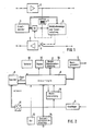
- the 1 consists of two identically constructed regenerators 1 and 2 for two transmission directions and a common device for fault location.
- this has an address memory 3 for the address assigned to the intermediate regenerator.
- the address is stored unchangeably in this address memory and therefore belongs inseparably to this device, just as a serial number cannot be changed and is inseparable from a device.
- the address is, for example, a specific number for this device in a dual representation, which is chosen such that two different intermediate regenerators have never stored the same number as the address in their address memory 3.
- the address memory 3 is a digital read-only memory, the programming of which cannot be changed.
- a loop formation is also possible in the new intermediate regenerator according to FIG. 1 in that the output of the regenerator 1 for one transmission direction is connected to the input of the regenerator 2 for the other transmission direction via a controllable switch S.
- a galvanic isolation 4 is inserted, which is indicated by a transformer.
- the end point of the system is the end point that sends in the direction of the regenerator 1, that is to say in the illustration according to FIG. 1 "on the left side" of the system.
- a command detection and control circuit 5 is connected via the circuit 4 provided for electrical isolation to the output of the regenerator 1 and also to the output of the address memory 3.
- the command detection and control circuit 5 is capable of comparing the location or remote control Compare the address sent out and received by all intermediate regenerators with the individual address stored in the address memory 3 and also to recognize the commands sent from the end point and to initiate the execution of the commands. Instructions are to be understood as those which are in connection with the address of a special intermediate rain rators are sent out and are therefore directed only to this special intermediate regenerator and those commands which are sent out unrelated to any address and are directed to all intermediate regenerators of the system. In the intermediate regenerator shown in Fig.
- the command detection and control circuit 5 controls the switch S upon receipt of a corresponding command so that it assumes the switch position, not shown, and thus the loop closes and, in turn, controls a transmitter SE with a corresponding command, which can be connected on the input side to the address memory 3 and on the output side via the switch S to the input of the regenerator 2, so that it sends out the address of the intermediate regenerator. Examples of this for cooperation with a locating device of the system according to the invention to be explained are also given.
- FIG. 2 is provided for a bidirectional message transmission system with the intermediate regenerators according to the invention according to FIG Carrying out the fault location offers.
- a word generator 7 controlled by the control logic 6 is used to generate and send out these commands.
- the locating device according to FIG. 2 works as described below with the intermediate regenerator according to FIG. 1.
- the locating device When the locating device is connected to the terminal for fault location, it initially has no information about which addresses the intermediate regenerators of the system have and which address-provided intermediate regenerators are located at which location within the message transmission path. The locating device therefore initially has no possibility of specifically controlling the intermediate regenerators.
- the devices according to the invention to be described with reference to FIG. 2 are present in the locating device, which enable the locating device to query the intermediate regenerators one after the other according to their local order in the system for their addresses and these in a memory together with the location the intermediate regenerators to save.
- this can be carried out either only once after starting up the locating device or from time to time, triggered by manual operation or by a clock or by remote control from a computer.
- the control logic 6 is connected to a memory 8, in which the address of an intermediate regenerator and, on the other hand, its position within the system are stored. These two pieces of information are assigned to one another in the memory, so that the information for an intermediate regenerator in the memory 8 is that it has an address XYZ and, viewed from the locating terminal, is, for example, the fifth of the intermediate regenerators of the system located one behind the other. If any of the intermediate regenerators on the route sends its address to the locating device after a query which is yet to be explained, then this arrives at a receiver 9, the output of which is connected to a measuring device 10 and to a series-parallel converter 11.
- the measuring device When the control logic 6 gives the intermediate regenerators the command to send out their address, the measuring device receives a trigger signal from the control logic and is thus in a position when the receiver 9 receives an address between the sending of the query command and the arrival of the latter Address elapsed time to measure. The measuring device gives this measurement result to the control logic 6, which then recognizes on the basis of the transit times that it was an intermediate regenerator with a specific location from which the address was just received. (The system's intermediate regenerators follow one another at approximately regular intervals). After this evaluation of the received address, the parallel-series converter 11 enters the address in the memory 8 and at the same time the control logic enters the location of the associated intermediate regenerator in this memory. The address is stored in the memory 8 together with the associated location.
- the intermediate regenerators are queried for their addresses as follows: initiated by an operator via a keyboard 12 connected to the control logic 6 or automatically, depending on the status of a clock 13 connected to the control logic 6, or by a computer connected to the control logic 6 connected computer interface circuit 14 remotely controlled, the control logic 6 begins the polling process. For this purpose, it causes the word generator 7 to send out the word W1 via the system in order to request all intermediate regenerators to send their address back to the locating device.
- Each intermediate regenerator recognizes this word in its command recognition and control circuit 5 (FIG. 1), which then switches the switch S in each intermediate regenerator and closes the loop and immediately afterwards causes the transmitter SE to address the address stored in the address memory 3 via the regenerator 2 to be sent on the transmission path towards the locating device.
- the runtime is measured for the address, the location of the intermediate regenerator sending the address is determined as a function thereof, and the received address is stored in the memory 8 together with the associated location of the intermediate regenerator.
- the control logic 6 then causes the word generator 7 to send the word W3 to the intermediate regenerators in connection with the address just received and stored.
- the command recognition and control circuit 5 of the first intermediate regenerator now recognizes the own address sent by the locating device and the word W3 and then assumes the waiting state. This means that it brings the switch S back into the position shown in FIG. 1, so that the loop formation in the first intermediate regenerator breaks up and connects this intermediate regenerator to the second intermediate regenerator behind it and maintains this connection even if it again uses the word W1 (command for sending addresses).
- an intermediate regenerator thus ignores the reception of the word W1, the word W2 and the word W3 and remains unchanged in this state. Only the word W4, which gives the command for all intermediate regenerators to assume the operating state, ends the waiting state of an intermediate regenerator.
- the word generator of the locating device sends the word W1 over the transmission link to all intermediate regenerators.
- the first intermediate regenerator in the waiting state ignores this command and maintains the switch position shown in FIG. 1, in which it is connected to the one behind it. Those behind react to the word W1 as described above by closing the loop and sending their address via their regenerator 2 in the direction of the locating device.
- the second intermediate regenerator is connected to the locating device via the first intermediate regenerator, while the intermediate regenerators behind them are cut off from the transmission path to the locating device because of the loop closure present in each case, ie they send their address "into space".
- the address of the second intermediate regenerator is now received in the locating device and, as described for the address of the first intermediate regenerator above, is stored in the memory 8 together with the associated location. Thereupon, the word generator 7 of the locating device sends the word W3 provided with the address of the second intermediate regenerator via the transmission link, which causes this second intermediate regenerator to assume the waiting state.
- the command detection and control circuit 5 effects a so-called "forced reset" in the operating state, regardless of the receipt of the word W4, if it is within a predetermined time, e.g. Has not received any of the words W1 to W3 for 10 seconds.
- the forced reset ensures that a faulty loop closure in any repeater is reversed after a short time and the transmission can only be briefly disturbed in the operating state.
- Words W1 to W4 are to be understood as n-bit words which contain the actual command with sufficient redundancy and security.
- the locating device After knowing the addresses of the existing intermediate regenerators and the associated location, the locating device is able to carry out measurements at any time in order to examine the quality of the transmission path from the locating terminal to one of the intermediate regenerators by remotely closing the loop in any intermediate regenerator.
- the locating device contains a display 15 connected to the control logic 6 and a printer interface circuit 16, which is also connected to the control logic 6 and allows measurement logs to be printed out on a printer.
- the word generator sends out the word W2 in connection with the address of this intermediate regenerator, which causes the loop to close.
- the word W is repeatedly shown in the transmitted test pattern in order to avoid that the forced reset is activated.
- the word W4 is sent, which brings all intermediate regenerators back into the operating state.
- the locating device for measuring the transmission link to the first intermediate regenerator sends the word W2 to this first intermediate regenerator, after measurement the word W3 to this intermediate regenerator and after measuring the transmission link to it second intermediate regenerator, the word W3 to this intermediate regenerator, etc. until the transmission path to all intermediate regenerators has been measured one after the other, whereupon the word W4, which concludes the entire measurement, is finally sent out, which brings all intermediate regenerators back into the operating state, if they have not already been through Forced reset went into this state by themselves.
Landscapes
- Physics & Mathematics (AREA)
- Electromagnetism (AREA)
- Engineering & Computer Science (AREA)
- Computer Networks & Wireless Communication (AREA)
- Signal Processing (AREA)
- Dc Digital Transmission (AREA)
- Small-Scale Networks (AREA)
- Time-Division Multiplex Systems (AREA)
Abstract
Für ein digitales Nachrichtenübertragungssystem mit einer Vielzahl von zwischen zwei Endstellen vorhandenen Zwischenregeneratoren (1,2), die von einer Endstelle aus zur Fehlerortung oder zur Fernsteuerung gezielt ansteuerbar sein sollen, werden gemäß der Erfindung Zwischenregeneratoren angegeben, die in ihrem Adreßspeicher (3) ihre Adresse unveränderbar, nach Art einer bei der Geräteherstellung üblichen Fabrikationsnummer, eingespeichert haben. Dies erspart jegliche Einstellarbeit bei der Installation von Zwischenregeneratoren in das Übertragungssystem. Im weiteren wird ein Ortungsgerät für ein solches Nachrichtenübertragungssystem angegeben, das in der Lage ist, die im System vorhandenen Zwischenregeneratoren nacheinander nach ihren Adressen und Standorten im System abzufragen und diese Adressen zusammen mit den zugehörigen Standorten in einen Speicher einzuspeichern. Die Zwischenregeneratoren enthalten dann entsprechende Einrichtungen, die mit diesem Ortungsgerät zusammenarbeiten.For a digital message transmission system with a large number of intermediate regenerators (1, 2) present between two end points, which should be selectively controllable from one end point for fault location or for remote control, intermediate regenerators are specified according to the invention, which have their address in their address memory (3) unchangeable, in the manner of a production number that is common in device manufacture. This saves any adjustment work when installing intermediate regenerators in the transmission system. Furthermore, a locating device for such a message transmission system is specified which is able to query the intermediate regenerators present in the system one after the other for their addresses and locations in the system and to store these addresses together with the associated locations in a memory. The intermediate regenerators then contain appropriate facilities that work with this locating device.
Description
Die Erfindung betrifft mit Adressen versehene Zwischenregeneratoren für ein digitales Nachrichtenübertragungssystem sowie ein Ortungsgerät für ein doppelt gerichtetes digitales Nachrichtenübertragungssystem mit solchen Zwischenregeneratoren und schließlich ein digitales Nachrichtenübertragungssystem mit Zwischenregeneratoren und einem Ortungsgerät.The invention relates to intermediate regenerators provided with addresses for a digital message transmission system and to a location device for a bidirectional digital message transmission system with such intermediate regenerators and finally to a digital message transmission system with intermediate regenerators and a locating device.
Bei digitalen Nachrichtenübertragungssystemen mit einer Vielzahl von Zwischenregeneratoren sind Einrichtungen gefordert, um nach Feststellung einer Störung der Nachrichtenübertragung von einer Endstelle des Systems aus den Ort des Fehlers auf der Übertragungsstrecke feststellen zu können. Bezüglich dieser Fehlerortung unterscheidet man zwischen Systemen, bei denen jeder Zwischenregenerator eine eigene Adresse hat und dadurch gezielt angesteuert werden kann und Systemen mit einer adressenfreien Fehlerortung.In the case of digital message transmission systems with a large number of intermediate regenerators, devices are required in order to be able to determine the location of the error on the transmission link after a fault in the message transmission has been determined from an end point in the system. With regard to this fault location, a distinction is made between systems in which each intermediate regenerator has its own address and can thus be controlled in a targeted manner, and systems with an address-free fault location.
Gemäß der DE-A1-29 42 410 liegt bei den Systemen der ersten Art ein Problem darin, daß die Adresse eines Zwischenregenerators individuell eingestellt werden muß, so daß wegen dieses Problems die Systeme der zweiten Art häufig bevorzugt werden. Aus der DE-C1-35 22 446 ist für ein System der ersten Art ein Zwischenregenerator bekannt, der einen Adressenspeicher für eine digitale Adresse aufweist. Es ist dort gesagt, daß diese Adresse die dem Zwischenregenerator zugeordnete Adresse ist, jedoch ist nichts darüber ausgesagt, nach welchem Kriterium oder auf welche Weise die Zuordnung der Adresse zum Zwischenregenerator erfolgt ist auf welche Weise die den Zwischenregeneratoren zugeordneten Adressen in das Ortungsgerät eingegeben werden und auf welche Weise das Ortungsgerät Kenntnis davon erhält, an welchem Standort innerhalb des Systems sich der Zwischenregenerator mit einer bestimmten Adresse befindet.According to DE-A1-29 42 410, a problem with the systems of the first type is that the address of an intermediate regenerator must be set individually, so that the systems of the second type are often preferred because of this problem. From DE-C1-35 22 446 an intermediate regenerator is known for a system of the first type, which has an address memory for a digital address. It is said there that this address is the address assigned to the intermediate regenerator, but nothing is said about what criterion or how the address was assigned to the intermediate regenerator, how the addresses assigned to the intermediate regenerators are entered into the locating device, and the way in which the locating device obtains knowledge of the location within the system of the intermediate regenerator with a specific address.
Es ist die Aufgabe der Erfindung, für ein digitales Nachrichtenübertragungssystem mit Adressen aufweisenden Zwischenregeneratoren einen hinsichtlich der Adressenzuweisung geeigneten Zwischenregenerator und ein geeignetes Ortungsgerät anzugeben. Die Aufgabe wird bezüglich des Zwischenregenerators wie im Patentanspruch 1 und bezüglich des Ortungsgeräts wie im Patentanspruch 3 angegeben gelöst. Ein Nachrichtenübertragungssystem mit einem erfindungsgemäßen Zwischenregenerator und einem erfindungsgemäßen Ortungsgerät ist Gegenstand des Patentanspruchs 7. Weiterbildungen des Zwischenregenerators ergeben sich aus den Ansprüchen 2 und 5 und Weiterbildungen des Ortungsgeräts aus dem Anspruch 4.It is the object of the invention to provide an intermediate regenerator suitable for address assignment and a suitable locating device for a digital message transmission system with intermediate regenerators having addresses. The object is achieved with respect to the intermediate regenerator as specified in claim 1 and with respect to the locating device as specified in claim 3. A message transmission system with an intermediate regenerator according to the invention and a locating device according to the invention is the subject of claim 7. Further developments of the intermediate regenerator result from claims 2 and 5 and further developments of the locating device from claim 4.
Der erfindungsgemäße Zwischenregenerator und das damit ausgerüstete System hat den Vorteil, daß bei einer Installation eines Zwischenregenerators in das System kei ne Adresseneinstellung erforderlich ist, auch nicht beim nachträglichen Einbau eines zusätzlichen Zwischenregeneratoren oder beim Ersatz eines vorhandenen Zwischenregenerators durch einen neuen. Der Zwischenregenerator erhält bei seiner Herstellung seine Adresse, die ihm, wo immer er verwendet wird, wie eine Fabriknummer anhaftet.The intermediate regenerator according to the invention and the system equipped therewith has the advantage that when an intermediate regenerator is installed in the system, it does not Ne address setting is required, not even when installing an additional intermediate regenerator or replacing an existing intermediate regenerator with a new one. The intermediate regenerator receives its address when it is manufactured, which, wherever it is used, is attached to it like a serial number.
Die Erfindung wird nun anhand der Zeichnungen beispielsweise näher erläutert.
Es zeigen:
- Fig. 1 ein Blockschaltbild eines erfindungsgemäßen Zwischenregenerator und
- Fig. 2 ein Blockschaltbild eines erfindungsgemäßen Ortungsgeräts.
Show it:
- Fig. 1 is a block diagram of an intermediate regenerator according to the invention and
- Fig. 2 is a block diagram of a locating device according to the invention.
Der Zwischenregenerator nach Fig. 1 besteht aus zwei gleichartig aufgebauten Regeneratoren 1 und 2 für zwei Übertragungsrichtungen und einer gemeinsamen Einrichtung zur Fehlerortung. Diese hat als wesentliches Merkmal der Erfindung einen Adreßspeicher 3 für die dem Zwischenregenerator zugeordnete Adresse. In diesem Adreßspeicher ist die Adresse unveränderbar eingespeichert und gehört daher untrennbar zu diesem Gerät ebenso wie eine Fabrikationsnummer unveränderbar und untrennbar zu einem Gerät gehört. Die Adresse ist beispielsweise eine für dieses Gerät spezifische Zahl in dualer Darstellung, die so gewählt ist, daß niemals zwei verschiedene Zwischenregeneratoren dieselbe Zahl als Adresse in ihrem Adreßspeicher 3 gespeichert haben. Der Adreßspeicher 3 ist ein digitaler Festwertspeicher, dessen Programmierung unveränderbar ist.1 consists of two identically constructed regenerators 1 and 2 for two transmission directions and a common device for fault location. As an essential feature of the invention, this has an address memory 3 for the address assigned to the intermediate regenerator. The address is stored unchangeably in this address memory and therefore belongs inseparably to this device, just as a serial number cannot be changed and is inseparable from a device. The address is, for example, a specific number for this device in a dual representation, which is chosen such that two different intermediate regenerators have never stored the same number as the address in their address memory 3. The address memory 3 is a digital read-only memory, the programming of which cannot be changed.
Wie bei dem bekannten Zwischenregenerator ist auch bei dem neuen Zwischenregenerator nach Fig. 1 eine Schleifenbildung dadurch möglich, daß der Ausgang des Regenerators 1 für die eine Übertragungsrichtung mit dem Eingang des Regenerators 2 für die andere Übertragungsrichtung über einen steuerbaren Schalter S verbunden wird. In diese Verbindung ist eine galvanische Trennung 4 eingefügt, die durch einen Transformator angedeutet ist.As in the known intermediate regenerator, a loop formation is also possible in the new intermediate regenerator according to FIG. 1 in that the output of the regenerator 1 for one transmission direction is connected to the input of the regenerator 2 for the other transmission direction via a controllable switch S. In this connection, a galvanic isolation 4 is inserted, which is indicated by a transformer.
Für die gezeigte Umschalteinrichtung zur Schleifenbildung, die den Ausgang des Regenerators 1 mit dem Eingang des Regenerators 2 verbindet, ist Vorausgesetzt, daß die Endstelle des Systems, von der aus die Schleifenbildung oder irgendeine andere Maßnahme in dem Zwischenregenerator ausgelöst wird, diejenige Endstelle ist, die in Richtung des Regenerators 1 sendet, also sich in der Darstellung nach Figur 1 "auf der linken Seite" des Systems befindet.For the shown switching device for loop formation, which connects the output of the regenerator 1 with the input of the regenerator 2, it is assumed that the end point of the system, from which the loop formation or any other measure in the intermediate regenerator is triggered, is the end point that sends in the direction of the regenerator 1, that is to say in the illustration according to FIG. 1 "on the left side" of the system.
Eine Befehlserkennungs- und Steuerschaltung 5 ist über die zur galvanischen Trennung vorgesehene Schaltung 4 mit dem Ausgang des Regenerators 1 verbunden und außerdem mit dem Ausgang des Adreßspeichers 3. Die Befehlserkennungs- und Steuerschaltung 5 ist in der Lage,durch Vergleich der von der ortenden oder fernsteuernden Endstelle ausgesendeten und von allen Zwischenregeneratoren empfangenen Adresse mit der im Adreßspeicher 3 gespeicherten individuellen Adresse zu vergleichen und außerdem die von der Endstelle aus gesendeten Befehle zu erkennen und die Ausführung der Befehle zu veranlassen. Unter Befehlen sind solche zu verstehen, die in Verbindung mit der Adresse eines speziellen Zwischenregene rators ausgesendet werden und daher nur an diesen speziellen Zwischenregenerator gerichtet sind und solche Befehle, die ohne Zusammenhang mit irgendeiner Adresse ausgesendet werden und an alle Zwischenregeneratoren des Systems gerichtet sind. Bei dem in Fig. 1 gezeigten Zwischenregenerator, der für eine doppelt gerichtete Nachrichtenübertragung vorgesehen ist und eine Umschalteinrichtung zur Schleifenbildung enthält, steuert die Befehlserkennungs- und Steuerschaltung 5 bei Empfang eines entsprechenden Befehls den Schalter S so, daß er die nicht gezeigte Schalterstellung einnimmt und damit die Schleife schließt und sie steuert wiederum bei einem entsprechenden Befehl einen Sender SE, der eingangsseitig mit dem Adreßspeicher 3 und ausgangsseitig über den Schalter S mit dem Eingang des Regenerators 2 verbindbar ist, so, daß er die Adresse des Zwischenregenerators aussendet. Beispiele hierfür zur Zusammenarbeit mit einem zu erläuternden erfindungsgemäßen Ortungsgerät des Systems werden noch angegeben.A command detection and control circuit 5 is connected via the circuit 4 provided for electrical isolation to the output of the regenerator 1 and also to the output of the address memory 3. The command detection and control circuit 5 is capable of comparing the location or remote control Compare the address sent out and received by all intermediate regenerators with the individual address stored in the address memory 3 and also to recognize the commands sent from the end point and to initiate the execution of the commands. Instructions are to be understood as those which are in connection with the address of a special intermediate rain rators are sent out and are therefore directed only to this special intermediate regenerator and those commands which are sent out unrelated to any address and are directed to all intermediate regenerators of the system. In the intermediate regenerator shown in Fig. 1, which is provided for a bidirectional message transmission and contains a switching device for loop formation, the command detection and control circuit 5 controls the switch S upon receipt of a corresponding command so that it assumes the switch position, not shown, and thus the loop closes and, in turn, controls a transmitter SE with a corresponding command, which can be connected on the input side to the address memory 3 and on the output side via the switch S to the input of the regenerator 2, so that it sends out the address of the intermediate regenerator. Examples of this for cooperation with a locating device of the system according to the invention to be explained are also given.
Anhand von Fig. 2 wird nun das Blockschaltbild eines neuen Ortungsgeräts erläutert, das für ein doppelt gerichtetes Nachrichtenübertragungssystem mit den erfindungsgemäßen Zwischenregeneratoren nach Fig. 2 vorgesehen ist und das in Verbindung mit den neuen Zwischenregeneratoren Vorteile für ein solches Nachrichtenübertragungssystem hinsichtlich der Adressierbarkeit der Zwischenregeneratoren und der Durchführung der Fehlerortung bietet.The block diagram of a new locating device is now explained with reference to FIG. 2, which is provided for a bidirectional message transmission system with the intermediate regenerators according to the invention according to FIG Carrying out the fault location offers.
Die zentrale Einrichtung des Ortungsgeräts ist eine Steuerlogik 6, die Informationen von verschiedenen angeschlossenen Einrichtungen empfängt und Steuerinformationen zur Ansteuerung verschiedener anderer Einrichtungen abgibt. Zur Fernsteuerung verschiedener Funktionen in den Zwischenregeneratoren des Systems sind vier verschiedene vom Ortungsgerät auf die Strecke auszusendende Wörter vorgesehen, die entweder nur aus einem Befehl, der an alle Zwischenregeneratoren gerichtet ist, oder aus einem an einzelne Zwischenregeneratoren mit deren Adresse verbundenem Befehl stehen. Diese Wörter W1 bis W4 haben die folgende Bedeutung:
- W1: Befehl (an alle) ohne Adresse:
Adresse aussenden - W2: Befehl (an nur einen einzelnen) mit Adresse:
Schleife schließen - W3: Befehl (an nur einen einzelnen) mit Adressen:
Wartezustand einnehmen, - W4: Befehl (an alle) ohne Adresse:
Betriebszustand einnehmen.
- W1: command (to all) without address:
Send out address - W2: command (to only one) with address:
Close loop - W3: command (to only one) with addresses:
Assume waiting state, - W4: Command (to everyone) without address:
Assume operating state.
Zum Erzeugen und Aussenden dieser Befehle dient ein von der Steuerlogik 6 gesteuerter Wortgenerator 7.A word generator 7 controlled by the
Das Ortungsgerät nach Fig. 2 arbeitet wie nachstehend beschrieben wird mit dem Zwischenregenerator nach Fig. 1 zusammen. Wenn das Ortungsgerät zur Fehlerortung an die Endstelle angeschlossen wird, hat es zunächst keine Information darüber, welche Adressen die Zwischenregeneratoren des Systems haben und welcher mit einer Adresse versehene Zwischenregenerator an welchem Standort innerhalb der Nachrichtenübertragungsstrecke sich befindet. Das Ortungsgerät hat daher zunächst keine Möglichkeit, die Zwischenregeneratoren gezielt anzusteuern.The locating device according to FIG. 2 works as described below with the intermediate regenerator according to FIG. 1. When the locating device is connected to the terminal for fault location, it initially has no information about which addresses the intermediate regenerators of the system have and which address-provided intermediate regenerators are located at which location within the message transmission path. The locating device therefore initially has no possibility of specifically controlling the intermediate regenerators.
Um die dazu notwendigen Informationen zu erhalten, sind im Ortungsgerät die anhand von Fig. 2 zu beschreibenden erfindungsgemäßen Einrichtungen vorhanden, die dem Ortungsgerät ermöglichen, die Zwischenregeneratoren nacheinander entsprechend ihrer örtlichen Reihenfolge im System nach ihren Adressen abzufragen und diese in einem Speicher zusammen mit dem Standort der Zwischenregeneratoren zu speichern. Dies kann in einer sogenannten Initialisierungsphase entweder nur einmal nach Inbetriebnahme des Ortungsgeräts oder von Zeit zu Zeit, ausgelöst durch Handbetätigung oder durch eine Uhr oder durch Fernsteuerung von einem Rechner, durchgeführt werden.In order to obtain the information necessary for this, the devices according to the invention to be described with reference to FIG. 2 are present in the locating device, which enable the locating device to query the intermediate regenerators one after the other according to their local order in the system for their addresses and these in a memory together with the location the intermediate regenerators to save. In a so-called initialization phase, this can be carried out either only once after starting up the locating device or from time to time, triggered by manual operation or by a clock or by remote control from a computer.
Die Steuerlogik 6 ist mit einem Speicher 8 verbunden, in den einerseits die Adresse eines Zwischenregenerators und andererseits seine Position innerhalb des Systems eingespeichert wird. Im Speicher werden diese beiden Informationen einander zugeordnet, so daß sich für einen Zwischenregenerator im Speicher 8 die Information befindet, daß er eine Adresse XYZ hat und von der ortenden Endstelle aus gesehen z.B. der fünfte von den hintereinander befindlichen Zwischenregeneratoren des Systems ist. Sendet irgendeiner der auf der Strecke befindlichen Zwischenregeneratoren nach einer noch zu erläuternden Abfrage seine Adresse zum Ortungsgerät, so gelangt diese auf einen Empfänger 9, dessen Ausgang mit einer Meßeinrichtung 10 und mit einem Serien-Parallel-Wandler 11 verbunden ist. Die Meßeinrichtung empfängt, wenn die Steuerlogik 6 an die Zwischenregeneratoren den Befehl gibt, ihre Adresse auszusenden, ein Triggersignal von der Steuerlogik und ist somit in der Lage, wenn der Empfänger 9 eine Adresse empfängt, die zwischen dem Aussenden des Abfragebefehls und dem Eintreffen dieser Adresse verstrichene Laufzeit zu messen. Dieses Meßergebnis gibt die Meßeinrichtung an die Steuerlogik 6, die dann aufgrund der Laufzeiten erkennt, daß es ein Zwischenregenerator mit einem bestimmten Standort war, von dem gerade die Adresse empfangen wurde. (Die Zwischenregeneratoren des Systems folgen ungefähr in regelmäßigen Abständen aufeinander). Nach dieser Auswertung der empfangenen Adresse gibt der Parallel-Serien-Wandler 11 die Adresse in den Speicher 8 ein und gleichzeitig gibt die Steuerlogik den Standort des zugehörigen Zwischenregenerators in diesen Speicher ein. Im Speicher 8 wird die Adresse zusammen mit dem zugehörigen Standort abgespeichert.The
Die Abfrage der Zwischenregeneratoren nach ihren Adressen geschieht wie folgt: Veranlaßt durch eine Bedienungsperson über eine an die Steuerlogik 6 angeschlossene Tastatur 12 oder automatisch, abhängig vom Stand einer an die Steuerlogik 6 angeschlossenen Uhr 13,oder durch eine mit einem Rechner verbundene und an die Steuerlogik 6 angeschlossene Rechnerschnittstellenschaltung 14 ferngesteuert, beginnt die Steuerlogik 6 den Abfragevorgang. Hierzu veranlasst sie den Wortgenerator 7, das Wort W1 über das System auszusenden, um alle Zwischenregeneratoren zum Rücksenden ihrer Adresse zum Ortungsgerät aufzufordern. Jeder Zwischenregenerator erkennt dieses Wort in seiner Befehlserkennungs- und Steuerschaltung 5 (Fig. 1), die daraufhin in jedem Zwischenregenerator den Schalter S umschaltet und die Schleife schließt und unmittelbar danach den Sender SE veranlaßt, die im Adresse-Speicher 3 gespeicherte Adresse über den Regenerator 2 auf die Übertragungsstrecke in Richtung zum Ortungsgerät auszusenden. Da in diesem Zustand aber nur der erste Zwischenregenera tor (aus der Sicht der ortenden Endstelle) mit dieser ortenden Endstelle verbunden ist und die Übertragungsstrecke von den dahinterliegenden Zwischenregeneratoren zur ortenden Endstelle im jeweils davorliegenden Zwischenregenerator wegen der dort geschlossenen Schleife unterbrochen ist, gelangt nur die vom ersten Zwischenregenerator ausgesendete Adresse zum Ortungsgerät.The intermediate regenerators are queried for their addresses as follows: initiated by an operator via a
Dort wird, wie beschrieben,zu der Adresse die Laufzeit gemessen, davon abhängig der Standort des die Adresse sendenden Zwischenregenerators festgestellt und die empfangene Adresse zusammen mit dem zugehörigen Standort des Zwischenregenerators in den Speicher 8 eingespeichert. Daraufhin veranlaßt die Steuerlogik 6 den Wortgenerator 7, das Wort W3 in Verbindung mit der gerade empfangenen und eingespeicherten Adresse zu den Zwischenregeneratoren auszusenden. Die Befehlserkennungs- und Steuerschaltung 5 des ersten Zwischenregenerators erkennt nun die vom Ortungsgerät gesendete eigene Adresse und das Wort W3 und nimmt daraufhin den Wartezustand ein. Dies bedeutet, daß sie den Schalter S wieder in die in Fig. 1 gezeigte Stellung bringt, damit die Schleifenbildung im ersten Zwischenregenerator auftrennt und diesen Zwischenregenerator mit dem dahinterliegenden zweiten Zwischenregenerator verbindet und diese Verbindung auch dann beibehält, wenn sie erneut das Wort W1 (Befehl zur Adressenaussendung) empfängt. Im Wartezustand ignoriert ein Zwischenregenerator also den Empfang des Wortes W1, des Wortes W2 und des Wortes W3 und bleibt unverändert in diesem Zustand Nur das Wort W4, das für alle Zwischenregeneratoren gemeinsam den Befehl gibt, den Betriebszustand einzunehmen, beendet den Wartezustand eines Zwischenregenerators.There, as described, the runtime is measured for the address, the location of the intermediate regenerator sending the address is determined as a function thereof, and the received address is stored in the memory 8 together with the associated location of the intermediate regenerator. The
Nachdem der erste Zwischenregenerator in den Wartezustand gebracht worden ist, sendet der Wortgenerator des Ortungsgeräts das Wort W1 über die Übertragungsstrecke zu allen Zwischenregeneratoren. Der im Wartezustand befindliche erste Zwischenregenerator ignoriert diesen Befehl und behält die in Fig. 1 gezeigte Schalterstellung bei, in der er mit dem dahinterliegenden verbunden ist. Die dahinterliegenden reagieren auf das Wort W1 wie oben beschrieben, indem sie die Schleife schliessen und ihre Adresse über ihren Regenerator 2 in Richtung zum Ortungsgerät aussenden. Jedoch ist zu diesem Zeitpunkt nur der zweite Zwischenregenerator über den ersten Zwischenregenerator mit dem Ortungsgerät verbunden, während die dahinterliegenden Zwischenregeneratoren wegen des im jeweils davorliegenden vorhandenen Schleifenschlusses vom Übertragungsweg zum Ortungsgerät abgeschnitten sind, also ihre Adresse "ins Leere" senden. Die Adresse des zweiten Zwischenregenerators wird nun im Ortungsgerät empfangen und wie für die Adresse des ersten Zwischenregenerators oben beschrieben zusammen mit dem zugehörigen Standort in den Speicher 8 eingespeichert. Daraufhin sendet der Wortgenerator 7 des Ortungsgeräts über die Übertragungsstrecke das mit der Adresse des zweiten Zwischenregenerators versehene Wort W3, das diesen zweiten Zwischenregenerator veranlaßt, den Wartezustand einzunehmen.After the first intermediate regenerator has been put on hold, the word generator of the locating device sends the word W1 over the transmission link to all intermediate regenerators. The first intermediate regenerator in the waiting state ignores this command and maintains the switch position shown in FIG. 1, in which it is connected to the one behind it. Those behind react to the word W1 as described above by closing the loop and sending their address via their regenerator 2 in the direction of the locating device. However, at this point in time only the second intermediate regenerator is connected to the locating device via the first intermediate regenerator, while the intermediate regenerators behind them are cut off from the transmission path to the locating device because of the loop closure present in each case, ie they send their address "into space". The address of the second intermediate regenerator is now received in the locating device and, as described for the address of the first intermediate regenerator above, is stored in the memory 8 together with the associated location. Thereupon, the word generator 7 of the locating device sends the word W3 provided with the address of the second intermediate regenerator via the transmission link, which causes this second intermediate regenerator to assume the waiting state.
In dieser Weise werden nacheinander alle Zwischenregeneratoren nach ihrer Adresse abgefragt und die Adressen zusammen mit dem zugehörigen Standorten in dem Speicher 8 gespeichert, bis die Abfrage nach dem letzten Zwischenregenerator das darauffolgende Endgerät erreicht. Empfängt dieses Endgerät das Wort W1, so schließt es auch eine Schleife und sendet als Antwort ein Wort, das dem Ortungsgerät mitteilt, daß sämtliche Zwischenregeneratoren von der Abfrage erfaßt worden sind und die Abfrage zu Ende ist, wenn das Ortungsgerät keine Information darüber hat, wieviele Zwischenregeneratoren sich auf der Übertragungsstrecke zwischen den beiden Endgeräten befinden. Nach Erhalt dieses Wortes sendet das Ortungsgerät über seinen Wortgenerator 7 das Wort W4, das sämtliche Zwischenregeneratoren und das ferne Endgerät in den Betriebszustand bringt, bei dem der Schalter S in der in Fig. 1 gezeigten Schalterstellung ist und die Befehlserkennungs- und Steuerschaltung 5 im Gegensatz zum Wartezustand einen erneut eingehenden Befehl zum Schleifenschluß ausführt.In this way, all intermediate regenerators are queried one after the other for their address and the addresses are stored together with the associated locations in the memory 8 until the query for the last intermediate regenerator reaches the subsequent terminal. If this terminal receives the word W1, it also closes a loop and sends a word in response that the Locator reports that all intermediate regenerators have been detected by the query and the query is over if the locator has no information about how many intermediate regenerators are on the transmission path between the two terminals. After receiving this word, the locating device transmits via its word generator 7 the word W4, which brings all intermediate regenerators and the remote terminal into the operating state in which the switch S is in the switch position shown in FIG. 1 and the command recognition and control circuit 5 in contrast executes a new incoming command to close the loop.
Die Befehlserkennungs- und Steuerschaltung 5 bewirkt eine sogenannte "Zwangsrücksetzung" in den Betriebszustand, unabhängig vom Empfang des Wortes W4, wenn sie innerhalb einer vorgegebenen Zeit, z.B. 10 Sekunden lang keines der Wörter W1 bis W3 empfangen hat. Durch die Zwangsrücksetzung ist sichergestellt, daß ein fehlerhaft auftretender Schleifenschluß in irgendeinem Zwischenverstärker nach kurzer Zeit wieder rückgängig gemacht wird und die Übertragung im Betriebszustand nur kurzzeitig gestört werden kann.The command detection and control circuit 5 effects a so-called "forced reset" in the operating state, regardless of the receipt of the word W4, if it is within a predetermined time, e.g. Has not received any of the words W1 to W3 for 10 seconds. The forced reset ensures that a faulty loop closure in any repeater is reversed after a short time and the transmission can only be briefly disturbed in the operating state.
Als Wörter W1 bis W4 sind n-Bit-Wörter zu verstehen, in welchen mit ausreichender Redundanz und Sicherheit der eigentliche Befehl enthalten ist.Words W1 to W4 are to be understood as n-bit words which contain the actual command with sufficient redundancy and security.
Nach Kenntnis der Adressen der vorhandenen Zwischenregeneratoren und des dazugehörigen Standortes ist das Ortungsgerät in der Lage, jederzeit Messungen durchzuführen, um die Qualität der Übertragungsstrecke vom ortenden Endgerät aus jeweils bis zu einem der Zwischenregeneratoren zu untersuchen, indem es ferngesteuert die Schleife in irgendeinem Zwischenregenerator schließt, ein Prüfmuster aussendet und das über die geschlossene Prüfschleife zurück zum Ortungsgerät gelangende Prüfmuster mit dem gesendeten vergleicht, um z.B. die Bitfehlerhäufigkeit zu messen. Zur Anzeige von Meßergebnissen enthält das Ortungsgerät ein an die Steuerlogik 6 angeschlossenes Display 15 und eine Drucker-Schnittstellenschaltung 16, die ebenfalls an die Steuerlogik 6 angeschlossen ist und das Ausdrucken von Meßprotokollen an einem Drucker erlaubt. Soll in einem speziellen irgendwo auf der Strecke liegenden Zwischenregenerator die Schleife geschlossen und eine Messung durchgeführt werden, so wird vom Wortgenerator das Wort W2 in Verbindung mit der Adresse dieses Zwischenregenerators ausgesendet, das den Schleifenschluß veranlaßt. Während des Meßvorganges wird in das ausgesendete Prüfmuster immer wieder das Wort W" eingeblendet, um zu vermeiden, daß die Zwangsrücksetzung aktiviert wird. Nach Beendigung der Messung wird das Wort W4 ausgesendet, das alle Zwischenregeneratoren wieder in den Betriebszustand bringt.After knowing the addresses of the existing intermediate regenerators and the associated location, the locating device is able to carry out measurements at any time in order to examine the quality of the transmission path from the locating terminal to one of the intermediate regenerators by remotely closing the loop in any intermediate regenerator. a Sends out the test pattern and compares the test pattern coming back to the locating device via the closed test loop with the transmitted one, for example to measure the bit error rate. To display measurement results, the locating device contains a
Falls die Übertragungsstrecken bis zu den nacheinanderfolgenden Zwischenregeneratoren nacheinander durchgemessen werden sollten, wird vom Ortungsgerät für die Messung der Übertragungsstrecke bis zum ersten Zwischenregenerator an diesen ersten Zwischenregenerator das Wort W2 gesendet, nach Messung das Wort W3 an diesen Zwischenregenerator und nach Messung der Übertragungsstrecke bis zu diesem zweiten Zwischenregenerator das Wort W3 zu diesem Zwischenregenerator usw. bis die Ubertragungsstrecke bis zu allen Zwischenregeneratoren nacheinander durchgemessen worden ist, worauf dann schließlich das die gesamte Messung abschließende Wort W4 ausgesendet wird, das alle Zwischenregeneratoren wieder in den Betriebszustand bringt, wenn sie nicht bereits vorher durch Zwangsrücksetzung von selbst in diesen Zustand gegangen sind.If the transmission links to the successive intermediate regenerators should be measured in succession, the locating device for measuring the transmission link to the first intermediate regenerator sends the word W2 to this first intermediate regenerator, after measurement the word W3 to this intermediate regenerator and after measuring the transmission link to it second intermediate regenerator, the word W3 to this intermediate regenerator, etc. until the transmission path to all intermediate regenerators has been measured one after the other, whereupon the word W4, which concludes the entire measurement, is finally sent out, which brings all intermediate regenerators back into the operating state, if they have not already been through Forced reset went into this state by themselves.
Wenn auch, wie vorstehend beschrieben, die Vorteile der Erfindung vorwiegend dann zum Tragen kommen, wenn der erfindungsgemäße Zwischenregenerator nach Figur 1 mit dem erfindungsgemäßen Ortungsgerät nach Figur 2 in einem doppelt gerichteten Nachrichtenübertragungssystem zusammenarbeitet, gehören in den Rahmen der Erfindung auch noch die folgenden Varianten:
- a) Der Zwischenregenerator ist nur für eine einzige Übertragungsrichtung vorhanden, hat eine Adresse unveränderbar eingespeichert, so daß bei seinem Einbau in ein Nachrichtenübertragungssystem keine Adresseneinstellung an ihm vorgenommen werden muß. Die Adresse, gewissermaßen seine Fabrikationsnummer, und eventuell der Standort, an dem er in das System eingebaut ist, wird dann in einen Plan aufgenommen, und an zentraler Stelle einem Ortungs- oder Fernsteuergerät entsprechend dem Plan eingegeben. Auch in diesem Fall hat der Zwischenregenerator eine Befehlserkennungs- und Steuerschaltung, die irgendwelche allgemein gültigen oder mit der Adresse des Zwischenregenerators verknüpften individuelle Befehle erkennt und deren Ausführung veranlaßt, z.B. Ein- und Ausschalten oder Erhöhung der Verringerung der Verstärkung. Ein Ortungsgerät nach Figur 2 ist in diesem Falle wegen des fehlenden Rückkanals nicht einsetzbar.
- b) Der Zwischenregenerator ist ein Zwischenregenerator üblicher Art, also mit einer Möglichkeit zur Schleifenbildung und mit einem Adreßspeicher, in den die Adresse sich veränderbar einspeichern läßt und mit einer Befehlserkennungs- und Steuerschaltung. Auch in diesem Falle hat es einen Vorteil, wenn das Ortungsgerät ein erfindungsgemäßes Ortungsgerät nach Figur 2 ist, da ein solches Ortungsgerät jederzeit in der Lage ist, die ihm "von Hand" eingegebene Information über die an den Zwischen regeneratoren eingestellten Adressen und die Standorte selbsttätig in der oben geschilderten Weise zu überprüfen. Der Zwischenregenerator ist dann jedoch insofern erfindungsgemäß abgeändert, als er die zur Zusammenarbeit mit dem Ortungsgerät notwendigen Einrichtungen (z.B. Sender SE zum Aussenden der Adresse) aufweist.
- a) The intermediate regenerator is only available for a single direction of transmission, has an address stored unchangeably, so that when it is installed in a message transmission system, no address setting has to be made on it. The address, so to speak his serial number, and possibly the location at which he is built into the system, is then recorded in a plan and entered in a central location or location control device according to the plan. In this case too, the intermediate regenerator has a command recognition and control circuit which recognizes any individual commands which are generally valid or which are linked to the address of the intermediate regenerator and causes them to be executed, for example switching on and off or increasing the reduction in gain. A locating device according to FIG. 2 cannot be used in this case because of the missing return channel.
- b) The intermediate regenerator is an intermediate regenerator of a conventional type, that is to say with a possibility of forming loops and with an address memory in which the address can be stored in a changeable manner and with a command recognition and control circuit. In this case, too, it has an advantage if the locating device is a locating device according to the invention as shown in FIG. 2, since such a locating device is able at any time to transmit the information "manually" entered to it to the intermediary addresses and the locations to be checked automatically in the manner described above. However, the intermediate regenerator is then modified according to the invention in that it has the facilities necessary for cooperation with the locating device (for example transmitter SE for sending the address).
Claims (7)
Applications Claiming Priority (2)
| Application Number | Priority Date | Filing Date | Title |
|---|---|---|---|
| DE19863638147 DE3638147A1 (en) | 1986-11-08 | 1986-11-08 | DIGITAL MESSAGE TRANSMISSION SYSTEM WITH ADDRESSING INTERMEDIATE REGENERATORS AND DEVICE FOR Fault Locating |
| DE3638147 | 1986-11-08 |
Publications (3)
| Publication Number | Publication Date |
|---|---|
| EP0267528A2 true EP0267528A2 (en) | 1988-05-18 |
| EP0267528A3 EP0267528A3 (en) | 1989-11-02 |
| EP0267528B1 EP0267528B1 (en) | 1993-08-11 |
Family
ID=6313502
Family Applications (1)
| Application Number | Title | Priority Date | Filing Date |
|---|---|---|---|
| EP87116189A Expired - Lifetime EP0267528B1 (en) | 1986-11-08 | 1987-11-04 | Digital data transmission system with adressable repeaters having fault localization devices |
Country Status (6)
| Country | Link |
|---|---|
| US (1) | US4939747A (en) |
| EP (1) | EP0267528B1 (en) |
| JP (1) | JPS63219250A (en) |
| AU (1) | AU595951B2 (en) |
| DE (2) | DE3638147A1 (en) |
| ES (1) | ES2044891T3 (en) |
Cited By (2)
| Publication number | Priority date | Publication date | Assignee | Title |
|---|---|---|---|---|
| EP0433527A1 (en) * | 1989-12-21 | 1991-06-26 | Zumtobel Aktiengesellschaft | Control arrangement for several consumers |
| WO1991010276A1 (en) * | 1989-12-21 | 1991-07-11 | Zumtobel Aktiengesellschaft | Control system for several consumers |
Families Citing this family (14)
| Publication number | Priority date | Publication date | Assignee | Title |
|---|---|---|---|---|
| GB8927623D0 (en) * | 1989-12-06 | 1990-02-07 | Bicc Plc | Repeaters for secure local area networks |
| CH682030A5 (en) * | 1991-01-15 | 1993-06-30 | Peter Vockenhuber | |
| US5422929A (en) * | 1991-11-13 | 1995-06-06 | Txport, Inc. | Telephone line repeater and method of testing same |
| US5600656A (en) * | 1993-06-10 | 1997-02-04 | Siemens Stromberg-Carlson | Remote loopback apparatus and method for telephone line repeaters |
| US5717714A (en) * | 1995-01-30 | 1998-02-10 | Level One Communications, Inc. | Inter-repeater backplane with mixed signal state machine interconnect |
| US5680113A (en) * | 1995-02-24 | 1997-10-21 | International Business Machines Corporation | Dynamic address assignments to serially connected devices |
| US5726993A (en) * | 1995-10-25 | 1998-03-10 | Siemens Telecom Networks | Signal detector for telephone line repeator remote loopback system |
| US5887050A (en) * | 1997-05-09 | 1999-03-23 | Siemens Building Technologies, Inc. | Repeater apparatus having isolation circuit |
| DE19942690A1 (en) * | 1999-09-07 | 2001-03-15 | Siemens Ag | Localization of a disturbed section in an active long-term connection |
| US6829292B1 (en) * | 2000-01-03 | 2004-12-07 | Symmetricom, Inc. | Increasing gain with isolating upstream and downstream filters and amplifiers |
| GB2363498B (en) * | 2000-06-16 | 2005-06-01 | Marconi Caswell Ltd | Transponder device for generating a data bearing output |
| US6795871B2 (en) | 2000-12-22 | 2004-09-21 | General Electric Company | Appliance sensor and man machine interface bus |
| US7558192B1 (en) * | 2004-05-03 | 2009-07-07 | Cisco Technology, Inc. | Method to increase system availability of critical hardware components |
| DE102008035785A1 (en) | 2007-08-08 | 2009-02-12 | Tridonicatco Gmbh & Co. Kg | Actuators e.g. emergency light, addressing method for room of e.g. house, involves identifying selected actuator based on measured line distance regarding position in assembly plan, and transmitting operating address to actuator |
Citations (1)
| Publication number | Priority date | Publication date | Assignee | Title |
|---|---|---|---|---|
| EP0143489A1 (en) * | 1983-11-17 | 1985-06-05 | Koninklijke Philips Electronics N.V. | Supervisory arrangement for a digital transmission system |
Family Cites Families (17)
| Publication number | Priority date | Publication date | Assignee | Title |
|---|---|---|---|---|
| US3950622A (en) * | 1974-10-15 | 1976-04-13 | Culbertson Industries Inc. | Line fault locating system |
| US4072923A (en) * | 1976-03-08 | 1978-02-07 | Western Geophysical Co. Of America | Multichannel seismic telemeter system and array former |
| IT1040148B (en) * | 1975-07-28 | 1979-12-20 | Sits Soc It Telecom Siemens | REMOTE SURVEILLANCE SYSTEM FOR PCM TRANSMISSION SYSTEMS |
| US4301538A (en) * | 1978-11-02 | 1981-11-17 | Compagnie Industrielle Des Telecommunications Cit-Alcatel | Remote surveillance and fault location unit for pulse regenerator repeaters |
| FR2444983A1 (en) * | 1978-12-22 | 1980-07-18 | Fillot Jean Jacques | SYSTEM FOR MONITORING AND REGULATING A TRANSMISSION LINK |
| FR2454728A1 (en) * | 1979-04-19 | 1980-11-14 | Telecommunications Sa | METHOD AND DEVICE FOR MONITORING DIGITAL OR ANALOG TELECOMMUNICATIONS LINKS |
| DE2942410A1 (en) * | 1979-10-19 | 1981-05-07 | Siemens AG, 1000 Berlin und 8000 München | ADDRESS-FREE ERROR LOCATION BY LOOP IN A MESSAGE ROUTE |
| FR2486335B1 (en) * | 1980-07-02 | 1988-03-11 | Telecommunications Sa | STEP-BY-STEP TELELOCATION INSTALLATION OF INTERMEDIATE AMPLIFICATION CIRCUITS OF A MIC LINK |
| AU552312B2 (en) * | 1982-02-08 | 1986-05-29 | Racal-Milgo Limited | Communication system |
| JPS59132265A (en) * | 1983-01-19 | 1984-07-30 | Nec Corp | Supervisory method of repeater in pcm carrier system |
| JPS59172861A (en) * | 1983-03-22 | 1984-09-29 | Toshiba Corp | Loop back control system |
| US4558464A (en) * | 1983-06-10 | 1985-12-10 | General Instrument Corporation | Address-programmable CATV converter |
| DE3401685A1 (en) * | 1984-01-19 | 1985-07-25 | Philips Patentverwaltung Gmbh, 2000 Hamburg | TROUBLESHOOTING METHOD |
| US4713808A (en) * | 1985-11-27 | 1987-12-15 | A T & E Corporation | Watch pager system and communication protocol |
| US4638298A (en) * | 1985-07-16 | 1987-01-20 | Telautograph Corporation | Communication system having message repeating terminals |
| US4653070A (en) * | 1985-09-11 | 1987-03-24 | Nec Corporation | Channel monitoring circuit for use in a repeater station over radio digital transmission |
| US4831558A (en) * | 1986-08-26 | 1989-05-16 | The Slope Indicator Company | Digitally based system for monitoring physical phenomena |
-
1986
- 1986-11-08 DE DE19863638147 patent/DE3638147A1/en not_active Withdrawn
-
1987
- 1987-11-04 DE DE8787116189T patent/DE3786983D1/en not_active Expired - Fee Related
- 1987-11-04 ES ES87116189T patent/ES2044891T3/en not_active Expired - Lifetime
- 1987-11-04 EP EP87116189A patent/EP0267528B1/en not_active Expired - Lifetime
- 1987-11-05 AU AU80824/87A patent/AU595951B2/en not_active Ceased
- 1987-11-05 US US07/117,595 patent/US4939747A/en not_active Expired - Fee Related
- 1987-11-06 JP JP62279435A patent/JPS63219250A/en active Pending
Patent Citations (1)
| Publication number | Priority date | Publication date | Assignee | Title |
|---|---|---|---|---|
| EP0143489A1 (en) * | 1983-11-17 | 1985-06-05 | Koninklijke Philips Electronics N.V. | Supervisory arrangement for a digital transmission system |
Cited By (3)
| Publication number | Priority date | Publication date | Assignee | Title |
|---|---|---|---|---|
| EP0433527A1 (en) * | 1989-12-21 | 1991-06-26 | Zumtobel Aktiengesellschaft | Control arrangement for several consumers |
| WO1991010276A1 (en) * | 1989-12-21 | 1991-07-11 | Zumtobel Aktiengesellschaft | Control system for several consumers |
| US5352957A (en) * | 1989-12-21 | 1994-10-04 | Zumtobel Aktiengessellschaft | Appliance control system with programmable receivers |
Also Published As
| Publication number | Publication date |
|---|---|
| EP0267528A3 (en) | 1989-11-02 |
| AU8082487A (en) | 1988-05-26 |
| DE3786983D1 (en) | 1993-09-16 |
| US4939747A (en) | 1990-07-03 |
| AU595951B2 (en) | 1990-04-12 |
| DE3638147A1 (en) | 1988-05-11 |
| EP0267528B1 (en) | 1993-08-11 |
| ES2044891T3 (en) | 1994-01-16 |
| JPS63219250A (en) | 1988-09-12 |
Similar Documents
| Publication | Publication Date | Title |
|---|---|---|
| DE1809913C3 (en) | Method and data transmission system for the transmission of data between a main unit and several terminal units | |
| DE3342430C2 (en) | ||
| EP0267528B1 (en) | Digital data transmission system with adressable repeaters having fault localization devices | |
| DE3431171A1 (en) | RAILWAY DETECTING DEVICE WITH AXLE PAYMENT | |
| DE2362344A1 (en) | DATA TRANSFER SYSTEM | |
| DE2817089B2 (en) | Alarm system | |
| DE2628905A1 (en) | TRAIN SECURITY AND CONTROL SYSTEM | |
| EP0256152B1 (en) | Method for generating a switching-signal in a broadcast or video receiver | |
| DE2701925A1 (en) | VEHICLE CONTROL SYSTEM WITH HIGH RELIABILITY | |
| DE2316662A1 (en) | ARRANGEMENT FOR COMPUTER-CONTROLLED REMOTE INQUIRIES OF DATA AND FOR COMPUTER-CONTROLLED OPERATION OF ACTUATORS | |
| DE2339392C3 (en) | Method for calling up outstations by a central station and CIRCUIT ARRANGEMENT FOR carrying out this method | |
| DE2264085C2 (en) | Telecontrol system with at least one main center to which a main network is assigned | |
| EP0797818B1 (en) | Process and device for radio communication in traffic guidance systems | |
| DE3327489C2 (en) | ||
| EP0214475B1 (en) | Circuit arrangement for the transmission of data signals between control devices interconnected by a loop system | |
| DE3136495C2 (en) | ||
| DE3029803C2 (en) | Cable television system | |
| DE3634019A1 (en) | DEVICE AND METHOD FOR SERIAL DATA EXCHANGE BETWEEN MORE THAN TWO PARTICIPANTS | |
| DE1925254C3 (en) | Device, in particular for railway safety, for the transmission of binary coded signals | |
| DE3047259C2 (en) | Circuit arrangement for the bidirectional transmission of information | |
| EP0036960A1 (en) | Method and circuitry for reception and transmission of data blocks, especially for railway systems | |
| DE2346749C2 (en) | Circuit arrangement for the secure sending and receiving of commands in telecontrol systems | |
| DE3726573C2 (en) | ||
| DE102015105873A1 (en) | Apparatus and method for transmitting consumption data of a consumer counter in a radio communication system | |
| EP0392246B1 (en) | Monitoring and control system for digital information transmission systems with master and substitution master |
Legal Events
| Date | Code | Title | Description |
|---|---|---|---|
| PUAI | Public reference made under article 153(3) epc to a published international application that has entered the european phase |
Free format text: ORIGINAL CODE: 0009012 |
|
| AK | Designated contracting states |
Kind code of ref document: A2 Designated state(s): AT BE CH DE ES FR GB IT LI NL SE |
|
| PUAL | Search report despatched |
Free format text: ORIGINAL CODE: 0009013 |
|
| AK | Designated contracting states |
Kind code of ref document: A3 Designated state(s): AT BE CH DE ES FR GB IT LI NL SE |
|
| 17P | Request for examination filed |
Effective date: 19891123 |
|
| 17Q | First examination report despatched |
Effective date: 19920130 |
|
| RAP3 | Party data changed (applicant data changed or rights of an application transferred) |
Owner name: ALCATEL SEL AKTIENGESELLSCHAFT |
|
| RBV | Designated contracting states (corrected) |
Designated state(s): DE ES FR GB IT |
|
| GRAA | (expected) grant |
Free format text: ORIGINAL CODE: 0009210 |
|
| AK | Designated contracting states |
Kind code of ref document: B1 Designated state(s): DE ES FR GB IT |
|
| GBT | Gb: translation of ep patent filed (gb section 77(6)(a)/1977) |
Effective date: 19930812 |
|
| REF | Corresponds to: |
Ref document number: 3786983 Country of ref document: DE Date of ref document: 19930916 |
|
| ITF | It: translation for a ep patent filed |
Owner name: DOTT. ANTONIO SERGI |
|
| ET | Fr: translation filed | ||
| REG | Reference to a national code |
Ref country code: ES Ref legal event code: FG2A Ref document number: 2044891 Country of ref document: ES Kind code of ref document: T3 |
|
| PLBE | No opposition filed within time limit |
Free format text: ORIGINAL CODE: 0009261 |
|
| STAA | Information on the status of an ep patent application or granted ep patent |
Free format text: STATUS: NO OPPOSITION FILED WITHIN TIME LIMIT |
|
| 26N | No opposition filed | ||
| PGFP | Annual fee paid to national office [announced via postgrant information from national office to epo] |
Ref country code: GB Payment date: 19971013 Year of fee payment: 11 |
|
| PGFP | Annual fee paid to national office [announced via postgrant information from national office to epo] |
Ref country code: FR Payment date: 19971113 Year of fee payment: 11 |
|
| PGFP | Annual fee paid to national office [announced via postgrant information from national office to epo] |
Ref country code: DE Payment date: 19971115 Year of fee payment: 11 |
|
| PGFP | Annual fee paid to national office [announced via postgrant information from national office to epo] |
Ref country code: ES Payment date: 19971117 Year of fee payment: 11 |
|
| PG25 | Lapsed in a contracting state [announced via postgrant information from national office to epo] |
Ref country code: GB Free format text: LAPSE BECAUSE OF NON-PAYMENT OF DUE FEES Effective date: 19981104 |
|
| PG25 | Lapsed in a contracting state [announced via postgrant information from national office to epo] |
Ref country code: ES Free format text: LAPSE BECAUSE OF THE APPLICANT RENOUNCES Effective date: 19981105 |
|
| GBPC | Gb: european patent ceased through non-payment of renewal fee |
Effective date: 19981104 |
|
| PG25 | Lapsed in a contracting state [announced via postgrant information from national office to epo] |
Ref country code: FR Free format text: LAPSE BECAUSE OF NON-PAYMENT OF DUE FEES Effective date: 19990730 |
|
| REG | Reference to a national code |
Ref country code: FR Ref legal event code: ST |
|
| PG25 | Lapsed in a contracting state [announced via postgrant information from national office to epo] |
Ref country code: DE Free format text: LAPSE BECAUSE OF NON-PAYMENT OF DUE FEES Effective date: 19990901 |
|
| REG | Reference to a national code |
Ref country code: ES Ref legal event code: FD2A Effective date: 20010402 |
|
| PG25 | Lapsed in a contracting state [announced via postgrant information from national office to epo] |
Ref country code: IT Free format text: LAPSE BECAUSE OF NON-PAYMENT OF DUE FEES;WARNING: LAPSES OF ITALIAN PATENTS WITH EFFECTIVE DATE BEFORE 2007 MAY HAVE OCCURRED AT ANY TIME BEFORE 2007. THE CORRECT EFFECTIVE DATE MAY BE DIFFERENT FROM THE ONE RECORDED. Effective date: 20051104 |