EP0267381A2 - Device for and use of a fibre-optical sensor to measure minimum extensions - Google Patents
Device for and use of a fibre-optical sensor to measure minimum extensions Download PDFInfo
- Publication number
- EP0267381A2 EP0267381A2 EP87112646A EP87112646A EP0267381A2 EP 0267381 A2 EP0267381 A2 EP 0267381A2 EP 87112646 A EP87112646 A EP 87112646A EP 87112646 A EP87112646 A EP 87112646A EP 0267381 A2 EP0267381 A2 EP 0267381A2
- Authority
- EP
- European Patent Office
- Prior art keywords
- optical fiber
- fiber optic
- fiber
- sensor
- optical
- Prior art date
- Legal status (The legal status is an assumption and is not a legal conclusion. Google has not performed a legal analysis and makes no representation as to the accuracy of the status listed.)
- Granted
Links
- 239000000835 fiber Substances 0.000 claims abstract description 50
- 239000013307 optical fiber Substances 0.000 claims abstract description 47
- 230000008859 change Effects 0.000 claims abstract description 18
- 230000003287 optical effect Effects 0.000 claims abstract description 13
- 238000011156 evaluation Methods 0.000 claims abstract description 12
- 230000005693 optoelectronics Effects 0.000 claims abstract description 9
- 230000008878 coupling Effects 0.000 claims abstract description 5
- 238000010168 coupling process Methods 0.000 claims abstract description 5
- 238000005859 coupling reaction Methods 0.000 claims abstract description 5
- 238000005259 measurement Methods 0.000 claims description 8
- 238000012544 monitoring process Methods 0.000 claims description 6
- 239000002184 metal Substances 0.000 claims description 3
- 229920002430 Fibre-reinforced plastic Polymers 0.000 claims description 2
- 239000002131 composite material Substances 0.000 claims description 2
- 238000010276 construction Methods 0.000 claims description 2
- 239000011151 fibre-reinforced plastic Substances 0.000 claims description 2
- 230000010363 phase shift Effects 0.000 claims description 2
- 238000011144 upstream manufacturing Methods 0.000 claims description 2
- 239000011162 core material Substances 0.000 description 6
- 230000010287 polarization Effects 0.000 description 6
- 230000000694 effects Effects 0.000 description 4
- 238000000034 method Methods 0.000 description 4
- 238000005452 bending Methods 0.000 description 3
- 238000005253 cladding Methods 0.000 description 3
- 230000035945 sensitivity Effects 0.000 description 3
- 230000008901 benefit Effects 0.000 description 2
- 239000011521 glass Substances 0.000 description 2
- 230000008569 process Effects 0.000 description 2
- 229910000831 Steel Inorganic materials 0.000 description 1
- 230000009471 action Effects 0.000 description 1
- 238000004458 analytical method Methods 0.000 description 1
- 230000006835 compression Effects 0.000 description 1
- 238000007906 compression Methods 0.000 description 1
- 230000001419 dependent effect Effects 0.000 description 1
- 238000011161 development Methods 0.000 description 1
- 238000010586 diagram Methods 0.000 description 1
- 238000005516 engineering process Methods 0.000 description 1
- 238000004519 manufacturing process Methods 0.000 description 1
- 238000012806 monitoring device Methods 0.000 description 1
- 239000004033 plastic Substances 0.000 description 1
- 229920003023 plastic Polymers 0.000 description 1
- 239000011513 prestressed concrete Substances 0.000 description 1
- 238000012545 processing Methods 0.000 description 1
- 230000005855 radiation Effects 0.000 description 1
- 230000002285 radioactive effect Effects 0.000 description 1
- 239000011347 resin Substances 0.000 description 1
- 229920005989 resin Polymers 0.000 description 1
- 239000010959 steel Substances 0.000 description 1
Images

Classifications
-
- G—PHYSICS
- G01—MEASURING; TESTING
- G01M—TESTING STATIC OR DYNAMIC BALANCE OF MACHINES OR STRUCTURES; TESTING OF STRUCTURES OR APPARATUS, NOT OTHERWISE PROVIDED FOR
- G01M11/00—Testing of optical apparatus; Testing structures by optical methods not otherwise provided for
- G01M11/08—Testing mechanical properties
- G01M11/083—Testing mechanical properties by using an optical fiber in contact with the device under test [DUT]
- G01M11/086—Details about the embedment of the optical fiber within the DUT
-
- G—PHYSICS
- G01—MEASURING; TESTING
- G01B—MEASURING LENGTH, THICKNESS OR SIMILAR LINEAR DIMENSIONS; MEASURING ANGLES; MEASURING AREAS; MEASURING IRREGULARITIES OF SURFACES OR CONTOURS
- G01B11/00—Measuring arrangements characterised by the use of optical techniques
- G01B11/16—Measuring arrangements characterised by the use of optical techniques for measuring the deformation in a solid, e.g. optical strain gauge
- G01B11/18—Measuring arrangements characterised by the use of optical techniques for measuring the deformation in a solid, e.g. optical strain gauge using photoelastic elements
-
- G—PHYSICS
- G01—MEASURING; TESTING
- G01L—MEASURING FORCE, STRESS, TORQUE, WORK, MECHANICAL POWER, MECHANICAL EFFICIENCY, OR FLUID PRESSURE
- G01L1/00—Measuring force or stress, in general
- G01L1/24—Measuring force or stress, in general by measuring variations of optical properties of material when it is stressed, e.g. by photoelastic stress analysis using infrared, visible light, ultraviolet
- G01L1/242—Measuring force or stress, in general by measuring variations of optical properties of material when it is stressed, e.g. by photoelastic stress analysis using infrared, visible light, ultraviolet the material being an optical fibre
Definitions
- the invention relates to the establishment of an optical waveguide sensor for measuring minimal strains and its use for strain measurements on components to be monitored.
- Optical fibers we use this term synonymous with “coated optical fibers”, have already been designed and set up for different sensors. Probably the most extensive is the group of fiber optic sensors for mechanical forces (such as tensile, compressive, bending and torsional forces), which indicate the resulting changes in length (such as elongation, compression, bending and twisting).
- the display means here is the change in light attenuation that occurs with the change in length.
- optical fiber sensor for tensile forces and its use for monitoring a bridge structure made of prestressed concrete is described in DE-C2-33 05 234.
- an optical fiber is embedded in a tensile wire made of a fiber-reinforced resin structure in order to be able to monitor this wire for tension, breakage or bending.
- the fiber optic cable is enclosed by a plastic layer that has an inhomogeneous structure, fiber optic cable, intermediate layer and wire are mechanically firmly connected to each other over the entire length, and the fiber optic cable has connections for a light continuity tester at both ends.
- this fiber optic tension sensor is further increased by the fact that at least one helix of a metal wire (steel wire) or a glass thread is wound around the fiber optic cable as an inhomogeneous intermediate layer (DE-A1-35 26 966).
- the display means is also the light attenuation (DE-U1-82 12 823), and there are fiber optic sensors for the electrical current strength is proposed, the display means being the Faraday effect.
- an optoelectronic current converter for measuring the current in a high-voltage cable which works in single-mode optical fiber using the Faraday effect (Z. etz Vol. 106 (1985) 1160).
- the Faraday effect under the action of a magnetic field, the polarization plane of linearly polarized light, which propagates (here in the monomode fiber) in the direction of the magnetic field lines, is rotated.
- the fiber optic sensor To determine the current values from the Faraday effect, the fiber optic sensor must be connected on the one hand to the polarizer and light source, and on the other hand to the analyzer and evaluation electronics.
- the invention now falls into the group of fiber optic sensors for mechanical forces, and it is based on the task of designing a fiber optic sensor for minimal strains and setting it up in such a way that, in conjunction with the optoelectronic transmitting and receiving devices, it deforms in the ⁇ m range. Area covered.
- the other task is to indicate its use for strain measurements.
- the fiber optic cable required for the phase sensor has a special structure that causes configuration birefringence. This can be achieved, for example, by applying an elliptical jacket around an optical fiber core (the optical fiber), which causes permanent anisotropic mechanical tension. Or, conversely, a round jacket is applied around an elliptical core. Or an optically anisotropic cladding is applied around a round core in such a way that the refractive index of the cladding is different in two mutually perpendicular axes.
- Claim 2 relates to an advantageous development of the device
- claims 3 and 4 relate to the use of the fiber optic phase sensor for monitoring components for critical deformations
- claims 5 to 7 relate to the use of the fiber optic phase sensor for strain measurements.
- the main advantage of the invention is that with the fiber optic phase sensor in conjunction with the optoelectronic transmitting, receiving and evaluating devices, a highly sensitive fiber optic sensor for minimal strains is obtained, with which deformations in the ⁇ m range can be detected. It is therefore particularly suitable as a sensor for measuring low strains, such as the deflection of support or support elements.
- the optical waveguide for measuring minimal expansions consists in that a polarization-maintaining, birefringent monomode optical fiber 4 is used as the optical fiber.
- This has, for example, an elliptical jacket around the round core, which causes permanent anisotropic mechanical tension.
- the FO 4 is combined with an upstream polarizer 2 and a coupling 3 and with a downstream analyzer 5 to form the FO phase sensor 6. This is preceded by a light transmitter 1, and a light receiver 7 and an electronic evaluation device 11 are connected downstream, fiber optic cables or cables 12 being used as connections.
- a laser or a laser diode is used as the transmitter 1, and a photodiode is used as the receiver 7.
- a computer 9 is installed in the evaluation device 11 on the receiver side and a controller 10 for the transmitter is installed on the transmitter side.
- the mode of operation of the fiber Explain the phase sensor as follows:
- the optical strain sensor works with a special fiber, namely with a polarization-maintaining single-mode fiber.
- an elliptical cladding was applied around the round core (the optical fiber), which causes permanent anisotropic (direction-dependent) mechanical tension.
- the optical waveguide becomes birefringent, ie an incident light wave is split into two partial waves.
- the main axes of the ellipse are at the same time the optical axes (perpendicular to the fiber optic axis, spatially fixed) with the refractive indices n o and n ao.
- Optical anisotropy and birefringence mean that the speed of light propagation depends in a characteristic way on the refractive index of the glass.
- the optical axes identify the polarization directions for which the refractive index difference n o - n ao becomes maximum.
- Linearly polarized light is shifted by the phase difference ⁇ as it passes through this optical fiber.
- the propagation of linearly polarized light in the birefringent optical fiber with the aforementioned axis position can be described in such a way that the incident wave is represented by superimposing two waves whose polarization directions correspond to the optical axes. After passing through the FO, the two waves are again superimposed, taking into account the phase difference ⁇ .
- the change in length of the optical fiber can be determined directly from the phase difference change in the light coupled into the optical fiber.
- the measurements of minimal strains are to be carried out in such a way that linearly polarized light is coupled into the polarization-maintaining and also birefringent single-mode optical fiber 4, which is shifted by the phase difference ⁇ when passing through the optical fiber, and which occurs when the optical fiber changes in length
- This fiber optic sensor is therefore particularly suitable as a sensor for measuring low strains, such as deflections of support or support elements.
- a change in length l of approximately 5 .mu.m with a measuring length l o 500 mm was sufficient to pass through the measuring range CD.
- a strain measurement with a display accuracy ⁇ l / l o by 10 ⁇ 6 is possible.
- the measuring speed only depends on the downstream electronics.
- the measuring range limited in the first application can be doubled if the measuring light is split into three channels using a grating. Then it is possible to determine the phase difference ⁇ modulo 2 ⁇ (module of congruence) with some arithmetic with similar accuracy. The interval 2 ⁇ can then also be exceeded, in particular in the case of dynamic processes.
- the measuring speed is of course reduced, but by detecting the number of phase shifts by 2 ⁇ in both directions, ie with the correct sign, larger changes in length can also be determined by an electronic counting process.
- the sensor concept according to the invention offers an excellent combination of high sensitivity and a large measuring range.
- the field of application of the fiber optic phase sensor includes the integral monitoring of metal and fiber composite constructions for critical deformations and structural damage.
- the fiber optic sensor is mechanically and permanently connected to the component to be monitored.
- embedding in the laminate is also possible.
- machine parts or bridge structures can be monitored for deflection, so that the dangers of operational failure are reduced.
- FIG. 5 shows how several fiber optic phase sensors 6 are arranged in the zones of an aircraft at risk of breakage, for example at different points in the tail unit 13, and how fiber optic cables 12 are connected from there to the optoelectronic transmitter 1 and receiver 7 arranged in the control room and the evaluation device 11 are guided.
Abstract
Description
Die Erfindung betrifft die Einrichtung eines Lichtwellenleiter-Sensors für die Messung minimaler Dehnungen sowie seine Verwendung für Dehnungsmessungen an zu überwachenden Bauteilen.The invention relates to the establishment of an optical waveguide sensor for measuring minimal strains and its use for strain measurements on components to be monitored.
Lichtwellenleiter (LWL), wir benutzen diesen Begriff gleichbedeutend mit "ummantelte optische Fasern", wurden bereits zu verschiedenen Sensoren ausgebildet und eingerichtet. Wohl am umfangreichsten ist die Gruppe der LWL-Sensoren für mechanische Kräfte (wie Zug-, Druck-, Biege- und Torsionskräfte), welche die dadurch hervorgerufenen Längenänderungen (wie Dehnung, Stauchung Biegung und Verdrehung) anzeigen. Das Anzeigemittel ist hier die mit der Längenänderung eintretende Änderung der Lichtdämpfung.Optical fibers (LWL), we use this term synonymous with "coated optical fibers", have already been designed and set up for different sensors. Probably the most extensive is the group of fiber optic sensors for mechanical forces (such as tensile, compressive, bending and torsional forces), which indicate the resulting changes in length (such as elongation, compression, bending and twisting). The display means here is the change in light attenuation that occurs with the change in length.
Ein solcher LWL-Sensor für Zugkräfte und seine Verwendung zur Überwachung eines Brückenbauwerks aus Spannbeton ist in der DE-C2-33 05 234 beschrieben. Hier ist ein LWL in einem zugfesten Draht aus einer faserverstärkten Harzstruktur eingebettet, um diesen Draht auf Zug, Bruch oder Biegung überwachen zu können. Dazu ist der LWL von einer Kunststoffschicht umschlossen, die eine inhomogene Struktur hat, LWL, Zwischenschicht und Draht sind über die ganze Länge mechanisch fest miteinander verbunden, und der LWL besitzt an seinen beiden Enden Anschlüsse für ein Licht-Durchgangsprüfgerät. Die Empfindlichkeit dieses LWL-Zugsensors wird dadurch noch erhöht, daß als inhomogene Zwischenschicht um den LWL mindestens eine Wendel eines Metalldrahtes (Stahldrahtes) oder eines Glasfadens gewickelt ist (DE-A1-35 26 966).Such an optical fiber sensor for tensile forces and its use for monitoring a bridge structure made of prestressed concrete is described in DE-C2-33 05 234. Here, an optical fiber is embedded in a tensile wire made of a fiber-reinforced resin structure in order to be able to monitor this wire for tension, breakage or bending. For this purpose, the fiber optic cable is enclosed by a plastic layer that has an inhomogeneous structure, fiber optic cable, intermediate layer and wire are mechanically firmly connected to each other over the entire length, and the fiber optic cable has connections for a light continuity tester at both ends. The sensitivity of this fiber optic tension sensor is further increased by the fact that at least one helix of a metal wire (steel wire) or a glass thread is wound around the fiber optic cable as an inhomogeneous intermediate layer (DE-A1-35 26 966).
Aus der Vielzahl der verschiedenen LWL-Sensoren seien hier nur die beiden folgenden erwähnt: Es gibt LWL-Sensoren für kleine radioaktive Strahlendosen, wobei das Anzeigemittel ebenfalls die Lichtdämpfung ist (DE-U1-82 12 823), und es sind LWL-Sensoren für die elektrische Stromstärke vorgeschlagen, wobei das Anzeigemittel der Faraday-Effekt ist.From the multitude of different fiber optic sensors, only the following two should be mentioned here: there are fiber optic sensors for small radioactive doses, the display means is also the light attenuation (DE-U1-82 12 823), and there are fiber optic sensors for the electrical current strength is proposed, the display means being the Faraday effect.
Dazu ist ein optoelektronischer Stromwandler zum Messen des Stromes in einem Hochspannungskabel bekannt, der mit Hilfe des Faraday-Effekts in Monomode-LWL arbeitet (Z. etz Bd. 106 (1985) 1160). Beim Faraday-Effekt wird unter der Einwirkung eines magnetischen Feldes die Polarisationsebene linear polarisierten Lichts, das sich (hier in dem Monomode-LWL) in Richtung der magnetischen Feldlinien ausbreitet, gedreht. Zur Ermittlung der Stromwerte aus dem Faraday-Effekt muß der LWL-Sensor einerseits mit Polarisator und Lichtquelle, andererseits mit Analysator und Auswerteelektronik verbunden sein.For this purpose, an optoelectronic current converter for measuring the current in a high-voltage cable is known, which works in single-mode optical fiber using the Faraday effect (Z. etz Vol. 106 (1985) 1160). In the Faraday effect, under the action of a magnetic field, the polarization plane of linearly polarized light, which propagates (here in the monomode fiber) in the direction of the magnetic field lines, is rotated. To determine the current values from the Faraday effect, the fiber optic sensor must be connected on the one hand to the polarizer and light source, and on the other hand to the analyzer and evaluation electronics.
Die Erfindung fällt nun in die Gruppe der LWL-Sensoren für mechanische Kräfte, und ihr liegt die Aufgabe zugrunde, einen LWL-Sensor für minimale Dehnungen auszubilden und ihn so einzurichten, daß er in Verbindung mit den optoelektronischen Sende- und Empfangsgeräten Verformungen im µm-Bereich erfaßt. Die weitere Aufgabe besteht darin, seine Verwendung für Dehnungsmessungen anzugeben.The invention now falls into the group of fiber optic sensors for mechanical forces, and it is based on the task of designing a fiber optic sensor for minimal strains and setting it up in such a way that, in conjunction with the optoelectronic transmitting and receiving devices, it deforms in the μm range. Area covered. The other task is to indicate its use for strain measurements.
Die Lösung dieser Aufgabe wird durch die kennzeichnenden Merkmale des Anspruchs 1 angegeben. Sie besteht im wesentlichen darin, daß als LWL ein polarisationserhaltender, doppelbrechender Monomode-LWL eingesetzt ist, und zur Bildung eines LWL-Phasensensors in Reihe geschaltet sind: ein Polarisator, eine Einkopplung, der LWL und ein Analysator. In den LWL wird linear polarisiertes Licht eingekoppelt, und die bei einer Längenänderung des LWL auftretende Phasendifferenzänderung wird von einem Empfänger und Auswertegerät erfaßt.The solution to this problem is indicated by the characterizing features of claim 1. It consists essentially in the fact that a polarization-maintaining, birefringent monomode optical fiber is used as the optical fiber and is connected in series to form an optical fiber phase sensor: a polarizer, a coupling, the optical fiber and an analyzer. Linearly polarized light is injected into the optical fiber, and the phase difference change that occurs when the optical fiber changes in length is detected by a receiver and evaluation device.
Der für den Phasensensor erforderliche LWL hat einen speziellen Aufbau, der eine Konfigurations-Doppelbrechung hervorruft. Dies kann beispielsweise dadurch erreicht werden, daß um einen LWL-Kern (die optische Faser) ein elliptischer Mantel aufgebracht ist, der eine permanente anisotrope mechanische Spannung hervorruft. Oder es ist umgekehrt um einen elliptischen Kern ein runder Mantel aufgebracht. Oder es ist um einen runden Kern ein optisch anisotroper Mantel dergestalt aufgebracht, daß der Brechungsindex des Mantels in zwei zueinander senkrechten Achsen unterschiedlich ist.The fiber optic cable required for the phase sensor has a special structure that causes configuration birefringence. This can be achieved, for example, by applying an elliptical jacket around an optical fiber core (the optical fiber), which causes permanent anisotropic mechanical tension. Or, conversely, a round jacket is applied around an elliptical core. Or an optically anisotropic cladding is applied around a round core in such a way that the refractive index of the cladding is different in two mutually perpendicular axes.
Der Anspruch 2 betrifft eine vorteilhafte Weiterbildung der Einrichtung, die Ansprüche 3 und 4 betreffen die Verwendung des LWL-Phasensensors zur Überwachung von Bauteilen auf kritische Verformungen, und die Ansprüche 5 bis 7 betreffen die Verwendung des LWL-Phasensensors zu Dehnungsmessungen.
Der wesentliche Vorteil der Erfindung liegt darin, daß man mit dem LWL-Phasensensor in Verbindung mit den optoelektronischen Sende-, Empfangs- und Auswertegeräten einen hochempfindlichen LWL-Sensor für minimale Dehnungen erhält, womit man Verformungen im µm-Bereich erfassen kann. Damit eignet er sich besonders als Sensor für die Messung geringer Dehnungen, wie Durchbiegungen von Trag- oder Stützelementen.The main advantage of the invention is that with the fiber optic phase sensor in conjunction with the optoelectronic transmitting, receiving and evaluating devices, a highly sensitive fiber optic sensor for minimal strains is obtained, with which deformations in the μm range can be detected. It is therefore particularly suitable as a sensor for measuring low strains, such as the deflection of support or support elements.
Ausführungsbeispiele der Erfindung sind in der Zeichung dargestellt und werden im folgenden näher beschrieben. Es zeigen
- Fig. 1 die schematische Darstellung einer Labor-Meßeinrichtung mit einem LWL-Phasensensor,
- Fig. 2 einen abgemantelten Monomode-LWL mit Konfigurations-Doppelbrechung,
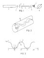
- Fig. 3 die graphische Darstellung des am Ausgang des Phasensensors erhaltenen Signals,
- Fig. 4 das Blockschaltbild eines Überwachungssystems mit einem LWL-Phasensensor, und
- Fig. 5 die Anordnung des Überwachungssystems mit mehreren LWL-Phasensensoren an bzw. in einem Flugzeugheck.
- 1 is a schematic representation of a laboratory measuring device with an optical fiber phase sensor,
- 2 shows a stripped single-mode optical fiber with configuration birefringence,
- 3 shows the graphic representation of the signal obtained at the output of the phase sensor,
- Fig. 4 shows the block diagram of a monitoring system with a fiber optic phase sensor, and
- Fig. 5 shows the arrangement of the monitoring system with several fiber optic phase sensors on or in an aircraft tail.
Bezeichnet sind mit
- 1 Lichtsender (Laser oder Laserdiode)
- 2 Polarisator
- 3 Einkopplung
- 4 polarisationserhaltender, doppelbrechender Monomode-LWL
- 4a der gleiche LWL abgemantelt (optische Faser)
- 5 Analysator
- 6 LWL-Phasensensor
- 7 Lichtempfänger (Fotodiode)
- 8 Anzeigegerät
- 9 Rechner (Datenverarbeitung)
- 10 Steuerung für den Sender
- 11 Auswertegerät
- 12 LWL-Verbindungskabel
- 13 Flugzeugheck mit LWL-Phasensensor-Überwachungseinrichtung.
- 1 light transmitter (laser or laser diode)
- 2 polarizer
- 3 coupling
- 4 polarization-maintaining, birefringent single-mode fiber
- 4a the same optical fiber stripped (optical fiber)
- 5 analyzer
- 6 FO phase sensor
- 7 light receivers (photodiode)
- 8 display device
- 9 computers (data processing)
- 10 Control for the transmitter
- 11 evaluation device
- 12 fiber optic connection cables
- 13 Airplane tail with fiber optic phase sensor monitoring device.
Wie die Fig. 1 und 4 zeigen, besteht die Einrichtung des Lichtwellenleiters für die Messung minimaler Dehnungen darin, daß als LWL ein polarisationserhaltender, doppelbrechender Monomode-LWL 4 eingesetzt ist. Dieser hat beispielsweise um den runden Kern einen elliptischen Mantel, der eine permanente anisotrope mechanische Spannung hervorruft. Der LWL 4 ist mit einem vorgeschalteten Polarisator 2 sowie einer Einkopplung 3 und mit einem nachgeschalteten Analysator 5 zu dem LWL-Phasensensor 6 zusammengefaßt. Diesem sind ein Lichtsender 1 vorgeschaltet, sowie ein Lichtempfänger 7 und ein elektronisches Auswertegerät 11 nachgeschaltet, wobei LWL-Leitungen oder -Kabel 12 als Verbindungen eingesetzt sind.As shown in FIGS. 1 and 4, the optical waveguide for measuring minimal expansions consists in that a polarization-maintaining, birefringent monomode optical fiber 4 is used as the optical fiber. This has, for example, an elliptical jacket around the round core, which causes permanent anisotropic mechanical tension. The FO 4 is combined with an
Als Sender 1 ist ein Laser oder eine Laserdiode, und als Empfänger 7 ist eine Fotodiode eingesetzt. In dem Auswertegerät 11 ist empfängerseitig ein Rechner 9 und senderseitig eine Steuerung 10 für den Sender eingebaut.A laser or a laser diode is used as the transmitter 1, and a photodiode is used as the
Anhand der Fig. 2 und 3 läßt sich die Funktionsweise des LWL Phasensensors wie folgt erläutern:
Wie oben erwähnt, arbeitet der optische Dehnungssensor mit einem speziellen LWL, und zwar mit einem polarisationserhaltenden Monomode-LWL. Dieser hat beim Produktionsprozeß um den runden Kern (die optische Faser) einen elliptischen Mantel aufgebracht bekommen, der eine permanente anisotrope (richtungsabhängige) mechanische Spannung hervorruft.2 and 3, the mode of operation of the fiber Explain the phase sensor as follows:
As mentioned above, the optical strain sensor works with a special fiber, namely with a polarization-maintaining single-mode fiber. During the production process, an elliptical cladding was applied around the round core (the optical fiber), which causes permanent anisotropic (direction-dependent) mechanical tension.
Durch die anisotrope Spannung wird der Lichtwellenleiter doppelbrechend, d. h. eine einfallende Lichtwelle wird in zwei Teilwellen aufgespalten. Die Hauptachsen der Ellipse sind gleichzeitig die optischen Achsen (senkrecht zur LWL-Achse, räumlich fest orientiert) mit den Brechungsindizes no und nao Optische Anisotropie und Doppelbrechung bedeuten, daß die Geschwindigkeit der Lichtausbreitung in charakteristischer Weise vom Brechungsindex des Glases abbhängt. Die optischen Achsen kennzeichnen dabei die Polarisationsrichtungen, für welche die Brechungsindexdifferenz no - nao maximal wird.Due to the anisotropic voltage, the optical waveguide becomes birefringent, ie an incident light wave is split into two partial waves. The main axes of the ellipse are at the same time the optical axes (perpendicular to the fiber optic axis, spatially fixed) with the refractive indices n o and n ao. Optical anisotropy and birefringence mean that the speed of light propagation depends in a characteristic way on the refractive index of the glass. The optical axes identify the polarization directions for which the refractive index difference n o - n ao becomes maximum.
Linear polarisiertes Licht wird beim Durchgang durch diesen LWL um die Phasendifferenz δ verschoben. Die Ausbreitung von linear polarisiertem Licht in dem doppelbrechenden LWL mit der vorerwähnten Achslage kann so beschrieben werden, daß man die einfallende Welle durch Uberlagerung von zwei Wellen darstellt, deren Polarisationsrichtungen mit den optischen Achsen übereinstimmen. Nach dem Durchlaufen des LWL werden die beiden Wellen wieder überlagert, wobei die Phasendifferenz δ zu berücksichtigen ist. Dies führt zu unterschiedlichen Polarisationsformen (linear, elliptisch, zirkular) des von dem LWL transmittierten Lichts, und eine optoelektronische Analyse des Polarisationszustandes erlaubt die Bestimmung von δ.Linearly polarized light is shifted by the phase difference δ as it passes through this optical fiber. The propagation of linearly polarized light in the birefringent optical fiber with the aforementioned axis position can be described in such a way that the incident wave is represented by superimposing two waves whose polarization directions correspond to the optical axes. After passing through the FO, the two waves are again superimposed, taking into account the phase difference δ. This leads to different forms of polarization (linear, elliptical, circular) of the light transmitted by the optical fiber, and an optoelectronic analysis of the polarization state allows the determination of δ.
Koppelt man linear polarisiertes Licht unter 45 ° zur optischen Achse in den LWL ein, so erhält man am Ausgang des LWL nach einem Polarisationsfilter ein Signal der Intensität I, das beschrieben werden kann durch die Funktion
I = Io (1 + cos δ).
Darin ist
Io die Intensität des optischen Signals am Eingang des LWL und δ die Phasendifferenz gemäß der Formel
δ = (2π/λ) (no - nao) lo
mit der Brechungsdifferenz no - nao = c . s
und λ = Wellenlänge des eingekoppelten Lichts
c = Brewsterkonstante des Kernmaterials
s = mechanische Spannung
lo = Länge des LWL.
Die Fig. 3 zeigt die graphische Darstellung dieser Funktion.If linearly polarized light is coupled into the optical fiber at 45 ° to the optical axis, a signal of intensity I is obtained at the output of the optical fiber after a polarization filter, which can be described by the function
I = I o (1 + cos δ).
In it
I o the intensity of the optical signal at the input of the fiber and δ the phase difference according to the formula
δ = (2π / λ) (n o - n ao ) l o
with the refraction difference n o - n ao = c. s
and λ = wavelength of the injected light
c = Brewster constant of the core material
s = mechanical tension
l o = fiber length.
3 shows the graphical representation of this function.
Da aber wie ersichtlich die Brechungsindexdifferenz nur von der mechanischen Spannung abhängt, wird die Phasendifferenzänderung Δδ nur noch von der Längenänderung lo abhängig gemäß der Formel
Δδ = (2π/λ) . K . lo
mit K = optomechanische Konstante des LWL.However, since, as can be seen, the difference in refractive index depends only on the mechanical stress, the change in phase difference Δδ only depends on the change in length l o according to the formula
Δδ = (2π / λ). K. l o
with K = optomechanical constant of the FO.
Daraus ergibt sich, daß man aus der Phasendifferenzänderung des in den LWL eingekoppelten Lichts direkt die Längenänderung des LWL bestimmen kann.It follows from this that the change in length of the optical fiber can be determined directly from the phase difference change in the light coupled into the optical fiber.
Demgemäß sind die Messungen minimaler Dehnungen (Längenänderungen) so auszuführen, daß linear polarisiertes Licht in den polarisationserhaltenden und zudem doppelbrechenden Monomode-LWL 4 eingekoppelt wird, das beim Durchgang durch den LWL um die Phasendifferenz δ verschoben wird, und die bei einer Längenänderung des LWL auftretende definierte Phasendifferenzänderung Δδ von dem optoelektronischen Auswertegerät 11 erfaßt und als Maß für die geometrische Änderung gewertet wird.Accordingly, the measurements of minimal strains (changes in length) are to be carried out in such a way that linearly polarized light is coupled into the polarization-maintaining and also birefringent single-mode optical fiber 4, which is shifted by the phase difference δ when passing through the optical fiber, and which occurs when the optical fiber changes in length Defined phase difference change Δδ detected by the
Erste Messungen ergaben, daß eine Änderung der Phasendifferenz von π durch eine Längenänderung von etwa 1,5 µm erzeugt wird. Damit eignet sich dieser LWL-Sensor besonders als Sensor für die Messung geringer Dehnungen, wie Durchbiegungen von Trag- oder Stützelementen.Initial measurements showed that a change in the phase difference of π is produced by a change in length of approximately 1.5 μm. This fiber optic sensor is therefore particularly suitable as a sensor for measuring low strains, such as deflections of support or support elements.
Anhand der Fig. 3 sei zum Meßverfahren noch ausgeführt:
Bei einer ersten Anwendung kann die Empfindlichkeit über die Meßlänge lo so angepaßt werden, daß der lineare Bereich A-B der Kurve I = f (δ) nicht überschritten wird. Man hat dann eine meßtechnisch sehr einfach zu handhabende Proportionalität zwischen der gemessenen Strahlungsleistung und der angelegten mechanischen Spannung, die nach dem Hook'schen Gesetz in Längenänderung skaliert werden kann.With reference to FIG. 3, the following still applies to the measuring method:
In a first application, the sensitivity can be adjusted over the measuring length l o so that the linear range AB of the curve I = f (δ) is not exceeded. One then has a proportionality, which is very easy to handle in terms of measurement technology, between the measured radiation power and the applied mechanical tension, which can be scaled according to Hook's law in length change.
Bei einer ersten Realisierung dieser Anwendung genügte eine Längenänderung l von ca. 5 um bei einer Meßlänge lo = 500 mm zum Durchfahren des Meßbereichs C-D. Bei angepaßter Elektronik ist damit eine Dehnungsmessung mit einer Anzeigegenauigkeit Δl/lo um 10⁻⁶ möglich.In a first implementation of this application, a change in length l of approximately 5 .mu.m with a measuring length l o = 500 mm was sufficient to pass through the measuring range CD. With adapted electronics, a strain measurement with a display accuracy Δl / l o by 10⁻⁶ is possible.
Die Meßgeschwindigkeit hängt bei stabilem Betrieb der Lichtquelle nur von der nachgeschalteten Elektronik ab.When the light source is in stable operation, the measuring speed only depends on the downstream electronics.
Der bei der ersten Anwendung eingeschränkte Meßbereich kann zunächst verdoppelt werden, wenn man das Meßlicht etwa mit Hilfe eines Gitters in drei Kanäle aufspaltet.
Dann ist es möglich, die Phasendifferenz δ modulo 2π (Modul der Kongruenz) mit etwas Arithmetik mit ähnlicher Genauigkeit zu bestimmen.
Insbesondere bei dynamischen Vorgängen kann dann auch das Intervall 2π überschritten werden. Zwar wird dabei natürlich die Meßgeschwindigkeit reduziert, aber indem die Zahl der Phasenverschiebungen um 2π in beiden Richtungen, also vorzeichenrichtig erfaßt wird, können auch größere Längenänderungen durch einen elektronischen Zählvorgang bestimmt werden.The measuring range limited in the first application can be doubled if the measuring light is split into three channels using a grating.
Then it is possible to determine the phase difference δ modulo 2π (module of congruence) with some arithmetic with similar accuracy.
The interval 2π can then also be exceeded, in particular in the case of dynamic processes. The measuring speed is of course reduced, but by detecting the number of phase shifts by 2π in both directions, ie with the correct sign, larger changes in length can also be determined by an electronic counting process.
Wie aus den vorstehenden Ausführungen hervorgeht, bietet das erfindungsgemäße Sensorkonzept eine vorzügliche Kombination von hoher Empfindlichkeit und großem Meßbereich.As can be seen from the above, the sensor concept according to the invention offers an excellent combination of high sensitivity and a large measuring range.
Das Einsatzgebiet des LWL-Phasensensors umfaßt die integrale Überwachung von Metall- und Faserverbundkonstruktionen auf kritische Verformungen und Strukturschäden. Dazu wird der LWL-Sensor mit dem zu überwachenden Bauteil mechanisch fest und dauerhaft verbunden. Bei Bauteilen aus faserverstärkten Kunststoffen ist auch eine Einbettung im Laminat möglich. Mit diesen LWL-Sensoren können insbesondere Flugzeugkomponenten, Maschinenteile oder Brückenkonstruktionen auf Durchbiegung überwacht werden, so daß die Gefahren eines Betriebsversagens reduziert werden.The field of application of the fiber optic phase sensor includes the integral monitoring of metal and fiber composite constructions for critical deformations and structural damage. For this purpose, the fiber optic sensor is mechanically and permanently connected to the component to be monitored. In the case of components made of fiber-reinforced plastics, embedding in the laminate is also possible. With these fiber optic sensors, in particular aircraft components, machine parts or bridge structures can be monitored for deflection, so that the dangers of operational failure are reduced.
So zeigt die Fig. 5, wie mehrere LWL-Phasensensoren 6 in den bruchgefährdeten Zonen eines Flugzeugs, etwa an verschiedenen Stellen des Leitwerks 13, angeordnet sind, und wie von dort LWL-Kabel 12 zu dem im Kontrollraum angeordneten optoelektronischen Sender 1 und Empfänger 7 sowie dem Auswertegerät 11 geführt sind.5 shows how several fiber
Claims (7)
dadurch gekennzeichnet, daß
- als LWL ein polarisationserhaltender, doppelbrechender Monomode-LWL (4) eingesetzt ist,
wozu dieser beispielsweise um den runden Kern (die optische Faser) einen elliptischen Mantel hat, der eine permanente anisotrope mechanische Spannung hervorruft,
- zur Bildung eines LWL-Phasensensors (6) in Reihe geschaltet sind: ein Polarisator (2), eine Einkopplung (3), der LWL (4) und ein Analysator (5), und
dem LWL-Phasensensor (6) ein Lichtsender (1) vorgeschaltet, und ein Lichtempfänger (7) sowie eine elektronische Auswerteinrichtung (11) nachgeschaltet sind, wobei LWL-Leitungen oder -Kabel (12) als Verbindungen eingesetzt sind.1. Setting up an optical fiber sensor (LWL sensor) for the measurement of minimal strains,
characterized in that
a polarization-maintaining, birefringent monomode optical fiber (4) is used as the optical fiber,
which is why, for example, it has an elliptical jacket around the round core (the optical fiber), which causes permanent anisotropic mechanical tension,
- To form an optical fiber phase sensor (6) are connected in series: a polarizer (2), a coupling (3), the optical fiber (4) and an analyzer (5), and
A light transmitter (1) is connected upstream of the fiber optic phase sensor (6) and a light receiver (7) and an electronic evaluation device (11) are connected downstream, fiber optic lines or cables (12) being used as connections.
Applications Claiming Priority (2)
| Application Number | Priority Date | Filing Date | Title |
|---|---|---|---|
| DE19863638345 DE3638345A1 (en) | 1986-11-10 | 1986-11-10 | SETUP AND USE OF A WAVE GUIDE SENSOR FOR MINIMUM EXPANSION |
| DE3638345 | 1986-11-10 |
Publications (3)
| Publication Number | Publication Date |
|---|---|
| EP0267381A2 true EP0267381A2 (en) | 1988-05-18 |
| EP0267381A3 EP0267381A3 (en) | 1990-05-02 |
| EP0267381B1 EP0267381B1 (en) | 1991-06-26 |
Family
ID=6313611
Family Applications (1)
| Application Number | Title | Priority Date | Filing Date |
|---|---|---|---|
| EP87112646A Expired - Lifetime EP0267381B1 (en) | 1986-11-10 | 1987-08-29 | Device for and use of a fibre-optical sensor to measure minimum extensions |
Country Status (3)
| Country | Link |
|---|---|
| US (1) | US4900920A (en) |
| EP (1) | EP0267381B1 (en) |
| DE (2) | DE3638345A1 (en) |
Cited By (2)
| Publication number | Priority date | Publication date | Assignee | Title |
|---|---|---|---|---|
| FR2707754A1 (en) * | 1993-07-12 | 1995-01-20 | Aerospatiale | On-board spacecraft structure having integrated dimensional sensors |
| DE10004384A1 (en) * | 2000-02-02 | 2001-08-16 | Daimler Chrysler Ag | Arrangement for detecting expansions, temperatures and their variations of coating applied to bearer has optical fiber on bearer surface with Bragg grid used as sensor in defined fiber section |
Families Citing this family (19)
| Publication number | Priority date | Publication date | Assignee | Title |
|---|---|---|---|---|
| US5182449A (en) * | 1990-02-06 | 1993-01-26 | The Boeing Corporation | System and method for structural monitoring using optical imaging of fiber sensors |
| DE4115370A1 (en) * | 1991-05-10 | 1992-11-26 | Asea Brown Boveri | Fibre=optic sensor for alternating electric fields or voltages - has piezoelectric element with attached optical fibre carrying two coherent light modes, and also fibre length variation detector |
| JP3065435B2 (en) * | 1992-07-31 | 2000-07-17 | 浜松ホトニクス株式会社 | Optical fiber component characteristic measuring device |
| DE4344856A1 (en) * | 1993-12-29 | 1995-07-06 | Abb Research Ltd | Fiber optic transmission sensor with modulator |
| AUPM547194A0 (en) * | 1994-05-06 | 1994-06-02 | University Of Sydney, The | Variable property light transmitting device |
| NO303470B1 (en) * | 1994-12-16 | 1998-07-13 | Safety One As | Method and system for continuous and global monitoring of dynamic loads |
| DE19540335A1 (en) * | 1995-10-28 | 1997-04-30 | Kloeckner Moeller Gmbh | Feed box |
| DE19705889C2 (en) * | 1997-02-15 | 1999-12-09 | Daimler Chrysler Ag | Angle of rotation sensor |
| DE19902783C2 (en) * | 1999-01-25 | 2002-11-07 | Ettemeyer Ag | measuring unit |
| US6542304B2 (en) | 1999-05-17 | 2003-04-01 | Toolz, Ltd. | Laser beam device with apertured reflective element |
| US6741189B1 (en) | 1999-10-06 | 2004-05-25 | Microsoft Corporation | Keypad having optical waveguides |
| US20040129868A1 (en) * | 2003-01-08 | 2004-07-08 | Siemens Vdo Automotive Corporation. | Deflection sensor |
| US7506549B2 (en) * | 2003-08-27 | 2009-03-24 | Airbus Uk Limited | Method and apparatus suitable for measuring the displacement or load on an aircraft component |
| EP1660851B1 (en) * | 2003-08-27 | 2017-10-25 | Airbus Operations Limited | Optically measuring the displacement or load for an aircraft component, landing gear, braking control |
| WO2005022100A1 (en) * | 2003-08-27 | 2005-03-10 | Airbus Uk Limited | Measuring load on an aircraft component by microwave distance links |
| DE102010005665A1 (en) | 2010-01-26 | 2011-07-28 | Dr. Ing. h.c. F. Porsche Aktiengesellschaft, 70435 | System for measuring torsion between two measuring points of measuring section in e.g. lorry, has polarization analyzer attached to optical waveguide at measuring point, where point is connected with another measuring point over waveguide |
| US8534132B1 (en) | 2010-11-19 | 2013-09-17 | Charles L. Purdy | Method for measuring tension in an anchored rod at an accessible end |
| DE102014002109A1 (en) * | 2014-02-15 | 2015-08-20 | Audi Ag | Component, component assembly and method for deformation detection of a component |
| DE102016125730A1 (en) * | 2016-12-27 | 2018-06-28 | fos4X GmbH | Device and method for measuring the torsion of a measuring object |
Citations (5)
| Publication number | Priority date | Publication date | Assignee | Title |
|---|---|---|---|---|
| JPS5940202A (en) * | 1982-08-31 | 1984-03-05 | Hitachi Cable Ltd | Strain gage using optical fiber for preserving plane of polarization |
| EP0120999A2 (en) * | 1983-03-30 | 1984-10-10 | Licentia Patent-Verwaltungs-GmbH | Fibre-optic sensor for force and pressure measurements, as well as for monitoring and protection purposes |
| US4515473A (en) * | 1984-09-13 | 1985-05-07 | Geo-Centers, Inc. | Photoelastic stress sensor signal processor |
| EP0144509A2 (en) * | 1983-11-09 | 1985-06-19 | Polaroid Corporation | Fiber optic interferometer transducer |
| DE3415855A1 (en) * | 1984-04-28 | 1985-11-07 | Licentia Patent-Verwaltungs-Gmbh, 6000 Frankfurt | Fibre-optic measuring device for measuring a tensile stress or flexure occurring on a component |
Family Cites Families (8)
| Publication number | Priority date | Publication date | Assignee | Title |
|---|---|---|---|---|
| DE2602691A1 (en) * | 1976-01-24 | 1977-07-28 | Caspers Friedhelm | Small length change measuring device - uses phase change of optical wave with change in glass fibre waveguide length to change voltage |
| DE2816682A1 (en) * | 1978-04-18 | 1979-12-20 | Max Planck Gesellschaft | ARRANGEMENT FOR DETERMINING THE INFLUENCE OF PHYSICAL QUANTITIES ON THE LENGTH OF A WAY |
| US4420251A (en) * | 1980-05-05 | 1983-12-13 | Rockwell International Corporation | Optical deformation sensor |
| DE8212823U1 (en) * | 1982-05-04 | 1982-08-19 | Felten & Guilleaume Energietechnik GmbH, 5000 Köln | LIGHTWAVE GUIDE SENSOR FOR SMALL RADIOACTIVE RADIO CAN |
| US4495411A (en) * | 1982-10-27 | 1985-01-22 | The United States Of America As Represented By The Secretary Of The Navy | Fiber optic sensors operating at DC |
| DE3305234C2 (en) * | 1983-02-16 | 1986-02-27 | Felten & Guilleaume Energietechnik GmbH, 5000 Köln | Tensile wire made from a fiber-reinforced resin structure with at least one optical waveguide enclosed therein |
| DE3526966A1 (en) * | 1984-11-14 | 1986-05-15 | Felten & Guilleaume Energietechnik GmbH, 5000 Köln | LIGHTWAVE GUIDE SENSOR FOR TOWING FORCES AND METHOD FOR THE PRODUCTION THEREOF |
| US4671659A (en) * | 1985-11-08 | 1987-06-09 | Martin Marietta Corporation | Fiber optic displacement sensor |
-
1986
- 1986-11-10 DE DE19863638345 patent/DE3638345A1/en not_active Withdrawn
-
1987
- 1987-08-29 EP EP87112646A patent/EP0267381B1/en not_active Expired - Lifetime
- 1987-08-29 DE DE8787112646T patent/DE3771031D1/en not_active Expired - Lifetime
- 1987-11-02 US US07/116,032 patent/US4900920A/en not_active Expired - Fee Related
Patent Citations (5)
| Publication number | Priority date | Publication date | Assignee | Title |
|---|---|---|---|---|
| JPS5940202A (en) * | 1982-08-31 | 1984-03-05 | Hitachi Cable Ltd | Strain gage using optical fiber for preserving plane of polarization |
| EP0120999A2 (en) * | 1983-03-30 | 1984-10-10 | Licentia Patent-Verwaltungs-GmbH | Fibre-optic sensor for force and pressure measurements, as well as for monitoring and protection purposes |
| EP0144509A2 (en) * | 1983-11-09 | 1985-06-19 | Polaroid Corporation | Fiber optic interferometer transducer |
| DE3415855A1 (en) * | 1984-04-28 | 1985-11-07 | Licentia Patent-Verwaltungs-Gmbh, 6000 Frankfurt | Fibre-optic measuring device for measuring a tensile stress or flexure occurring on a component |
| US4515473A (en) * | 1984-09-13 | 1985-05-07 | Geo-Centers, Inc. | Photoelastic stress sensor signal processor |
Non-Patent Citations (1)
| Title |
|---|
| PATENT ABSTRACTS OF JAPAN, Band 8, Nr. 141 (P-283)[1578], 30. Juni 1984; & JP-A-59 040 202 (HITACHI DENSEN K.K.) * |
Cited By (4)
| Publication number | Priority date | Publication date | Assignee | Title |
|---|---|---|---|---|
| FR2707754A1 (en) * | 1993-07-12 | 1995-01-20 | Aerospatiale | On-board spacecraft structure having integrated dimensional sensors |
| DE10004384A1 (en) * | 2000-02-02 | 2001-08-16 | Daimler Chrysler Ag | Arrangement for detecting expansions, temperatures and their variations of coating applied to bearer has optical fiber on bearer surface with Bragg grid used as sensor in defined fiber section |
| DE10004384C2 (en) * | 2000-02-02 | 2003-04-03 | Daimler Chrysler Ag | Arrangement and method for detecting strains and temperatures and their changes on a carrier, in particular one consisting of metal, plastic or ceramic carrier, applied topcoat |
| US6587188B2 (en) | 2000-02-02 | 2003-07-01 | Airbus Deutschland Gmbh | Method and sensor arrangement for measuring temperature and strain using an optical fiber embedded in a cover layer on a substrate |
Also Published As
| Publication number | Publication date |
|---|---|
| US4900920A (en) | 1990-02-13 |
| EP0267381A3 (en) | 1990-05-02 |
| EP0267381B1 (en) | 1991-06-26 |
| DE3771031D1 (en) | 1991-08-01 |
| DE3638345A1 (en) | 1988-05-19 |
Similar Documents
| Publication | Publication Date | Title |
|---|---|---|
| EP0267381A2 (en) | Device for and use of a fibre-optical sensor to measure minimum extensions | |
| EP0153997B1 (en) | Method for measuring force by help of strain induced double refraction in a monomode optical fiber and measuring device for carrying out the method | |
| EP0856737B1 (en) | Magneto optical current sensor | |
| EP0430060B1 (en) | Fibre-optic current transducer | |
| DE60216752T2 (en) | FIBER OPTIC RETROFIT POLARIMETRY | |
| EP0611974B1 (en) | Sensor head for a fibre optic current measuring apparatus | |
| DE19703128A9 (en) | Magneto-optical current sensor | |
| DE2703319A1 (en) | OPTO-ELECTRIC TUBE DEVICE AND METHOD OF MANUFACTURING IT | |
| EP1899700A1 (en) | Optical strain gauge strips | |
| EP0361588A1 (en) | Optical fibre sensor | |
| EP1101124B1 (en) | Polarimetric sensor for optical detection of a measured variable and utilization of said polarimetric sensor | |
| EP1896813A2 (en) | Optical strain gauge strips | |
| DE69630186T2 (en) | Fiber optic magnetic field sensor | |
| EP0477415B1 (en) | Optical current transducer | |
| DE3031961C2 (en) | Interferometric device for measuring physical quantities | |
| CN209746025U (en) | Current measurement system based on double fiber bragg gratings | |
| DE102017131388B4 (en) | Fiber optic torsion angle sensor and method of detecting a torsion angle | |
| EP1421393B1 (en) | Optical current sensors | |
| DE102017201523A1 (en) | Fiber optic detection device and method for operating such a fiber optic detection device | |
| DE3325945A1 (en) | Fibre-optical sensor and a sensor device containing the former | |
| EP3019826B1 (en) | Integrated optical coupler and fibre-optical system having such an integrated optical coupler | |
| DE102018205722A1 (en) | Distance measurement by reflectometry in optical waveguides | |
| DE102019112876B3 (en) | Fiber composite component, adapter unit, fiber optic sensor device and manufacturing process for this | |
| EP0331800B1 (en) | Fibre-optical phase sensor device to measure minimum elongations | |
| DE3822512A1 (en) | Force measuring device |
Legal Events
| Date | Code | Title | Description |
|---|---|---|---|
| PUAI | Public reference made under article 153(3) epc to a published international application that has entered the european phase |
Free format text: ORIGINAL CODE: 0009012 |
|
| AK | Designated contracting states |
Kind code of ref document: A2 Designated state(s): BE CH DE FR GB IT LI NL SE |
|
| PUAL | Search report despatched |
Free format text: ORIGINAL CODE: 0009013 |
|
| 17P | Request for examination filed |
Effective date: 19900219 |
|
| AK | Designated contracting states |
Kind code of ref document: A3 Designated state(s): BE CH DE FR GB IT LI NL SE |
|
| 17Q | First examination report despatched |
Effective date: 19900710 |
|
| GRAA | (expected) grant |
Free format text: ORIGINAL CODE: 0009210 |
|
| AK | Designated contracting states |
Kind code of ref document: B1 Designated state(s): BE CH DE FR GB IT LI NL SE |
|
| ITF | It: translation for a ep patent filed |
Owner name: ING. C. GREGORJ S.P.A. |
|
| ET | Fr: translation filed | ||
| REF | Corresponds to: |
Ref document number: 3771031 Country of ref document: DE Date of ref document: 19910801 |
|
| GBT | Gb: translation of ep patent filed (gb section 77(6)(a)/1977) | ||
| PGFP | Annual fee paid to national office [announced via postgrant information from national office to epo] |
Ref country code: BE Payment date: 19920428 Year of fee payment: 6 |
|
| PLBE | No opposition filed within time limit |
Free format text: ORIGINAL CODE: 0009261 |
|
| STAA | Information on the status of an ep patent application or granted ep patent |
Free format text: STATUS: NO OPPOSITION FILED WITHIN TIME LIMIT |
|
| 26N | No opposition filed | ||
| PGFP | Annual fee paid to national office [announced via postgrant information from national office to epo] |
Ref country code: SE Payment date: 19920708 Year of fee payment: 6 |
|
| PGFP | Annual fee paid to national office [announced via postgrant information from national office to epo] |
Ref country code: GB Payment date: 19920818 Year of fee payment: 6 |
|
| PGFP | Annual fee paid to national office [announced via postgrant information from national office to epo] |
Ref country code: FR Payment date: 19920827 Year of fee payment: 6 |
|
| PGFP | Annual fee paid to national office [announced via postgrant information from national office to epo] |
Ref country code: NL Payment date: 19920831 Year of fee payment: 6 |
|
| PGFP | Annual fee paid to national office [announced via postgrant information from national office to epo] |
Ref country code: CH Payment date: 19920902 Year of fee payment: 6 |
|
| PG25 | Lapsed in a contracting state [announced via postgrant information from national office to epo] |
Ref country code: GB Effective date: 19930829 |
|
| PG25 | Lapsed in a contracting state [announced via postgrant information from national office to epo] |
Ref country code: SE Effective date: 19930830 |
|
| PG25 | Lapsed in a contracting state [announced via postgrant information from national office to epo] |
Ref country code: LI Effective date: 19930831 Ref country code: CH Effective date: 19930831 Ref country code: BE Effective date: 19930831 |
|
| PGFP | Annual fee paid to national office [announced via postgrant information from national office to epo] |
Ref country code: DE Payment date: 19930831 Year of fee payment: 7 |
|
| BERE | Be: lapsed |
Owner name: FELTEN & GUILLEAUME ENERGIETECHNIK A.G. Effective date: 19930831 |
|
| PG25 | Lapsed in a contracting state [announced via postgrant information from national office to epo] |
Ref country code: NL Effective date: 19940301 |
|
| NLV4 | Nl: lapsed or anulled due to non-payment of the annual fee | ||
| GBPC | Gb: european patent ceased through non-payment of renewal fee |
Effective date: 19930829 |
|
| PG25 | Lapsed in a contracting state [announced via postgrant information from national office to epo] |
Ref country code: FR Effective date: 19940429 |
|
| REG | Reference to a national code |
Ref country code: CH Ref legal event code: PL |
|
| REG | Reference to a national code |
Ref country code: FR Ref legal event code: ST |
|
| EUG | Se: european patent has lapsed |
Ref document number: 87112646.2 Effective date: 19940310 |
|
| PG25 | Lapsed in a contracting state [announced via postgrant information from national office to epo] |
Ref country code: DE Effective date: 19950801 |
|
| PG25 | Lapsed in a contracting state [announced via postgrant information from national office to epo] |
Ref country code: IT Free format text: LAPSE BECAUSE OF NON-PAYMENT OF DUE FEES Effective date: 20050829 |