EP0265969A2 - Wheel spin control apparatus for use in an automobile - Google Patents
Wheel spin control apparatus for use in an automobile Download PDFInfo
- Publication number
- EP0265969A2 EP0265969A2 EP87115998A EP87115998A EP0265969A2 EP 0265969 A2 EP0265969 A2 EP 0265969A2 EP 87115998 A EP87115998 A EP 87115998A EP 87115998 A EP87115998 A EP 87115998A EP 0265969 A2 EP0265969 A2 EP 0265969A2
- Authority
- EP
- European Patent Office
- Prior art keywords
- braking
- control
- wheel
- spin
- control apparatus
- Prior art date
- Legal status (The legal status is an assumption and is not a legal conclusion. Google has not performed a legal analysis and makes no representation as to the accuracy of the status listed.)
- Granted
Links
- 238000001514 detection method Methods 0.000 claims abstract description 6
- 230000003313 weakening effect Effects 0.000 claims abstract 4
- 230000003247 decreasing effect Effects 0.000 claims abstract 3
- 230000001629 suppression Effects 0.000 claims abstract 3
- 230000009467 reduction Effects 0.000 claims description 12
- 238000012935 Averaging Methods 0.000 claims 2
- 238000006722 reduction reaction Methods 0.000 description 11
- 239000012530 fluid Substances 0.000 description 8
- 230000000694 effects Effects 0.000 description 7
- 238000009987 spinning Methods 0.000 description 6
- 230000007423 decrease Effects 0.000 description 4
- 238000000034 method Methods 0.000 description 3
- 230000001133 acceleration Effects 0.000 description 2
- 238000010586 diagram Methods 0.000 description 2
- 230000001141 propulsive effect Effects 0.000 description 2
- 238000009877 rendering Methods 0.000 description 2
- 238000006243 chemical reaction Methods 0.000 description 1
- 239000000306 component Substances 0.000 description 1
- 238000007689 inspection Methods 0.000 description 1
- 238000004519 manufacturing process Methods 0.000 description 1
- 230000000284 resting effect Effects 0.000 description 1
- 230000035939 shock Effects 0.000 description 1
Images
Classifications
-
- B—PERFORMING OPERATIONS; TRANSPORTING
- B60—VEHICLES IN GENERAL
- B60K—ARRANGEMENT OR MOUNTING OF PROPULSION UNITS OR OF TRANSMISSIONS IN VEHICLES; ARRANGEMENT OR MOUNTING OF PLURAL DIVERSE PRIME-MOVERS IN VEHICLES; AUXILIARY DRIVES FOR VEHICLES; INSTRUMENTATION OR DASHBOARDS FOR VEHICLES; ARRANGEMENTS IN CONNECTION WITH COOLING, AIR INTAKE, GAS EXHAUST OR FUEL SUPPLY OF PROPULSION UNITS IN VEHICLES
- B60K17/00—Arrangement or mounting of transmissions in vehicles
- B60K17/04—Arrangement or mounting of transmissions in vehicles characterised by arrangement, location, or kind of gearing
- B60K17/16—Arrangement or mounting of transmissions in vehicles characterised by arrangement, location, or kind of gearing of differential gearing
-
- B—PERFORMING OPERATIONS; TRANSPORTING
- B60—VEHICLES IN GENERAL
- B60T—VEHICLE BRAKE CONTROL SYSTEMS OR PARTS THEREOF; BRAKE CONTROL SYSTEMS OR PARTS THEREOF, IN GENERAL; ARRANGEMENT OF BRAKING ELEMENTS ON VEHICLES IN GENERAL; PORTABLE DEVICES FOR PREVENTING UNWANTED MOVEMENT OF VEHICLES; VEHICLE MODIFICATIONS TO FACILITATE COOLING OF BRAKES
- B60T8/00—Arrangements for adjusting wheel-braking force to meet varying vehicular or ground-surface conditions, e.g. limiting or varying distribution of braking force
- B60T8/17—Using electrical or electronic regulation means to control braking
- B60T8/175—Brake regulation specially adapted to prevent excessive wheel spin during vehicle acceleration, e.g. for traction control
-
- B—PERFORMING OPERATIONS; TRANSPORTING
- B60—VEHICLES IN GENERAL
- B60K—ARRANGEMENT OR MOUNTING OF PROPULSION UNITS OR OF TRANSMISSIONS IN VEHICLES; ARRANGEMENT OR MOUNTING OF PLURAL DIVERSE PRIME-MOVERS IN VEHICLES; AUXILIARY DRIVES FOR VEHICLES; INSTRUMENTATION OR DASHBOARDS FOR VEHICLES; ARRANGEMENTS IN CONNECTION WITH COOLING, AIR INTAKE, GAS EXHAUST OR FUEL SUPPLY OF PROPULSION UNITS IN VEHICLES
- B60K28/00—Safety devices for propulsion-unit control, specially adapted for, or arranged in, vehicles, e.g. preventing fuel supply or ignition in the event of potentially dangerous conditions
- B60K28/10—Safety devices for propulsion-unit control, specially adapted for, or arranged in, vehicles, e.g. preventing fuel supply or ignition in the event of potentially dangerous conditions responsive to conditions relating to the vehicle
- B60K28/16—Safety devices for propulsion-unit control, specially adapted for, or arranged in, vehicles, e.g. preventing fuel supply or ignition in the event of potentially dangerous conditions responsive to conditions relating to the vehicle responsive to, or preventing, skidding of wheels
Abstract
Description
- The present invention generally relates to a wheel spin control apparatus for use in an automotive vehicle for minimizing the spinning of a driven wheel and, more particularly, to the control apparatus operable to control both the braking force, delivered to the driven wheel, and the engine torque, thereby to quickly and effectively minimize the spinning of the driven wheel of an automotive vehicle which would occur, during, for example, the start or acceleration of the automotive vehicle.
- An automotive vehicle usually has at least one pair of driven wheels which are coupled together through a differential gear assembly which is in turn coupled with an engine. It has often been experienced that, when a driver starts or accelerates the automotive vehicle, for example, with a full throttle open, an extremely high engine torque is delivered to the driven wheels so that the drive forces applied to the driven wheels will be greater than the frictional forces between the tires on the driven wheels and the road surface. Accordingly, the driven wheels slip or spin excessively relative to the road surface. An efficient and effective transfer of the wheel traction from the tires to the road surface can be achieved when the speeds of the driven wheels' rotation slightly exceed the vehicle speed with a small amount of spin occurring between the driven wheel tire and the road surface. Thus, the excessive spin results in a loss of the engine power and a reduction of driving efficiency. This is also true even in the case where the automotive vehicle is driven at a moderate engine torque, but starts on a slippery road surface.
- As such, numerous wheel spin control apparatuses have hitherto been suggested for relieving the excessive slip to a value required to achieve the maximum traction, that is, the maximized transfer of a tractive force from the driven wheels onto the road surface. For example, some are designed to apply a braking force to the driven wheel, and some others are designed to reduce the engine torque, in the event that the detection of the wheel speeds indicates incipient spin conditions.
- A combined version of these two types is disclosed, for example, in Japanese Laid-open Patent Publication No. 58-16948, laid open to public inspection on January 31, 1983. According to this publication, the wheel spin control apparatus is selectively operable in two modes; the braking control mode and the torque control mode. The braking control mode is brought into effect only when one of the left-hand and right-hand driven wheels tends to spin, so that the braking force can be applied to such one of the driven wheels, thereby to substantially eliminate an unbalanced condition of the driven wheels. On the other hand, the torque control mode is brought into effect when both the left-hand and right-hand driven wheels tend to spin and, also, when one of the driven wheels tends to spin during a high speed driving, so that the engine torque can be reduced. Thus, according to the above described prior art, the braking control mode and the torque control mode are independently performed based on the behavior of the driven wheels.
- It is generally known that the response to a control of the braking force is remarkably faster than that of the engine torque. Accordingly, it is desired that the control of the wheel spin by the application of the braking force to the driven wheels is to be effected not only for minimizing the unbalanced condition of the driven wheels, but also for a case when both the left-hand and right-hand driven wheels tend to spin. In the latter case, the braking force should be applied for a length of time required for reducing the torque of the engine, in response to the control under the torque control mode, to a level low enough to alleviate the excessive wheel spin.
- However, the control of the wheel spin by the application of the braking force results in the consumption of extra energy for forcibly suppressing the engine. If the system is so arranged as to release the braking control mode as early as possible through a gradual change from the braking control mode to the torque control mode such that the braking control mode is superseded by the torque control mode, the excessive wheel spin could be reduced with less engine power loss. According to the above described prior art, however, the braking control mode and the torque control mode are carried out independently of each other and, therefore, it has been extremely difficult to establish a control system by which the excessive wheel spin can be obviated in dependence on both the braking force and the engine torque.
- Therefore, the present invention has for its essential object to provide an improved automotive wheel spin control operable to control both the braking force, delivered to the driven wheel, and the engine torque, thereby to quickly and effectively minimize the spinning of the driven wheel of an automotive vehicle which would occur, during, for example, the start or acceleration of the automotive vehicle.
- According to one feature of the present invention, the braking control is effected based only on the behavior of the driven wheels, so as to relieve the wheel spin to a proper value regardless of whether only one of the left-hand and right-hand driven wheels tends to spin or whether both of them tend to spin.
- On the other hand, the torque control is performed in connection with the result of the braking control. In other words, in carrying out the torque control, the magnitude of the braking force produced during the braking control mode is measured or inferred and the engine torque is then controlled by an amount corresponding to the measured or inferred value. It is preferable that while the torque control is performed, reference is made to the behavior of the driven wheels. When the engine torque actually decreases according to the dynamic characteristic of the engine, the excessive wheel spin will be relieved in a quantity corresponding to the reduction of the engine torque. Then, the braking control acts to reduce the braking force, allowing the torque control to supersede the braking control.
- In a preferred embodiment of the present invention, a smaller one of the two braking forces applied to the respective left-hand and right-hand driven wheels is used as the measured or inferred value to supersede the braking control with the torque control.
- According to the prior art, when the braking force is controlled to a certain magnitude to reduce the excessive wheel spin to an optimum spin so as to produce the maximum traction, such a braking force is maintained at the same magnitude. In such a case, since the torque control is carried out in reference to only the behavior of the driven wheels, no control necessary to permit the torque control to supersede the braking control can be effected.
- In contrast thereto, according to the present invention, since the torque control is effected in dependence on the braking control, the braking force once applied for the purpose of reducing the excessive wheel spin is progressively reduced to permit the torque control to supersede the braking control. As a consequence, the wheel spin can be controlled to an optimum value at which the traction can be maximized.
- These and other objects and features of the present invention will become readily understood from the following description taken in conjunction with preferred embodiments thereof with reference to the accompanying drawings, in which:
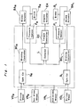
- Fig. 1 is a schematic circuit block diagram showing an automotive wheel spin control apparatus according to a first preferred embodiment of the present invention;
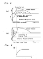
- Fig. 2 shows graphs each illustrating the manner in which the excessive wheel spin is alleviated;
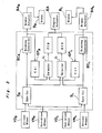
- Fig. 3 is a diagram similar to Fig. 1, but showing another preferred embodiment of the present invention;
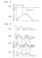
- Figs. 4 and 5 are graphs showing characteristics of a braking controller used in the apparatus; and
- Fig. 6 is a graph showing characteristics of a brake actuator used in the apparatus.
- Before the description of the present invention proceeds, it is to be noted that like parts are designated by like reference numerals or characters. It is also to be noted that, in describing the present invention, reference is made to an automotive vehicle having a pair of front non-driven wheels and a pair of rear driven wheels.
- Referring now to Fig. 1, a wheel spin control apparatus shown therein comprises first and second driven wheel speed sensors VDL and VDR for detecting, and generating output signals indicative of, the speeds of rotation of the left-hand and right-hand driven wheels, respectively; first and second non-driven wheel speed sensors VNL and VNR for detecting, and generating output signals indicative of, the speeds of rotation of the left-hand and right-hand non-driven wheels, respectively; first and second spin output units SL and SR, each operable to generate a respective spin signal indicative of the amount of spin occurring in the associated driven wheel; and first and second braking controllers BCL and BCR. Each of the first and second braking controllers BCL and BCR is so designed and so operable as to generate a respective first command required to apply or increase the braking force to be applied to an associated wheel brake unit BL or BR through an associated brake actuator BAL or BAR in the event that the excessively large wheel spin has taken place or is likely to occur and also to generate a respective second command required to reduce or remove the braking force in the event that the wheel spin has become excessively small or is likely to become excessively small.
- Each of the brake actuators BAL and BAR is operable in response to the first command from the associated brake controller BCL or BCR to increase the braking force to be applied to the associated brake unit BL or BR and, in response to the second command from the same brake controller BCL or BCR, to decrease the braking force applied to the associated brake unit BL or BR.
- Each of the spin output units SL and SR may be employed in the form of a subtracter operable to calculate a difference in level between the outputs from the wheel speed sensors VDL and VNL or between VDR and VNR, that is, the difference between the speed of rotation of the left-hand driven wheel and that of the left-hand non-driven wheel, or between the speed of rotation of the right-hand driven wheel and that of the right-hand non-driven wheel.
- It is to be noted that, although the amount of the wheel spin can be indicated by the difference between the speed of rotation of each of the driven wheels and the vehicle speed (an average value between the speeds of rotation of the left-hand and right-hand non-driven wheels), it is desirable to effect a correction to the amount of wheel spin particularly during the cornering of the automotive vehicle. To this end, the difference in speed of rotation between the left-hand and right-hand non-driven wheels, or between the right-hand driven wheels and the right-hand non-driven wheels, may be used as a parameter representative of the amount of cornering error. A method of effecting such correction during the cornering of the automotive vehicle is disclosed, for example, in Japanese Patent Application No. 60-201233, filed on September 11, 1985, by the same assignee as the present application.
- The wheel spin control apparatus also comprises first and second pressure sensors PL and PR, the first pressure sensor PL being operable to detect and generate a first pressure signal indicative of the magnitude of the braking force exerted by the first brake actuator BAL on the left-hand driven wheel through the brake unit BL. The second pressure sensor PR is operable to detect and generate a second pressure signal indicative of the magnitude of the braking force exerted by the second brake actuator BAR on the right-hand driven wheel through the brake unit BR. The first and second pressure signals emerging from the first and second pressure sensors PL and PR, respectively, are applied to a selector L which compares the first and second pressure signals with each other and applies to a torque controller EC one of the first and second pressure signals which is lower in level than the other of the first and second pressure signals.
- The torque controller EC is so arranged to operate in response to the output from the selector L to generate a command necessary to cause an engine actuator EA to increase or decrease the engine torque depending on the signal delivered by the output from the selector L.
- While the wheel spin control apparatus according to the first preferred embodiment of the present invention is so constructed as hereinbefore described, the present invention is generally featured in that the control performed by the torque controller EC depends on the first and second pressure signals from the first and second pressure sensors PL and PR, not on the outputs from the first and second wheel spin output units SL and SR.
- Next, the operation of the wheel spin control apparatus described above will now be described with reference to Fig. 2, graphs (a) and (b).
- It is now assumed that the automotive vehicle stands still with the left-hand and right-hand driven wheels resting, respectively, on a slippery surface and a normal surface of a roadway. The slippery road surface may be an iced road surface, a snow-covered road surface or a sand-covered road surface and is generally characterized by a relatively low µ(a coefficient of friction relative to the normal road surface), whereas the normal surface is characterized by a relatively high µ. When a driver of the automotive vehicle depresses an accelerator pedal, both of the driven wheels undergo a moderate spin and the vehicle starts its movement with accelerated velocity appropriate to the slippery road surface. The behavior of the right- and left-hand driven wheels during this condition are illustrated in Fig. 2, graphs (a) and (b), respectively.
- It is assumed that the engine torque transmitted to the left-hand driven wheel for a given amount of depression of the accelerator pedal in the automotive vehicle has a power of 10. Similarly, the engine torque transmitted to the right-hand driven wheel has a power of 10. In this case, the left-hand driven wheel on the slippery road surface would move the vehicle with a force (referred to as an effective force) of 3 and would undergo a spinning with a force (referred to as an excessive for) of 7, as shown in Fig. 2, graph (b). On the other hand, the right-hand driven wheel on the normal road surface would move the vehicle with an effective force of 6 and would undergo a spinning with an excessive force of 4, as shown in Fig. 2, graph (a). This is particularly true where the left-hand and right-hand driven wheels are not coupled directly together.
- However, since the automotive vehicles usually have a differential gear unit through which the engine torque is distributed to both the left-hand and right-hand driven wheels, the greater effective force of the two driven wheels would be reduced to be equal to the smaller effective force. Therefore, the effective force of the right-hand driven wheel, which ought to be 6, is limited to 3 and the remaining force of 3 would be transmitted through the differential gear unit to the left-hand driven wheel thereby to promote the further spinning of the left-hand driven wheel. Such wheel spins are detected by the respective spin output units SL and SR. Immediately after the detection by the wheel spins occurring in the left-hand and right-hand driven wheels, the braking controller BCL and BCR generate respective output signals which are in turn applied to the associated brake actuators BAL and BAR to bring the latter into operation. Accordingly, through the brake units BL and BR, a braking force of 4 and a braking force of 7 are applied to the right-hand driven wheel and the left-hand driven wheel, respectively, so that the excessive wheel spins occurring in the left-hand and right-hand driven wheels can be alleviated in a short time. During this process, the effective propulsive force of the right-hand driven wheel increases relatively to the increase of the braking force applied to the left-hand driven wheel. When the braking force applied to the left-hand driven wheel attains 3, the right-hand driven wheel could exhibit a propulsive force of 6 appropriate to the friction coefficient µ of the road surface.
- The braking forces applied to the associated right-hand and left-hand driven wheels are detected by the pressure sensors PR and PL which subsequently provides the second and first pressure signals, respectively, said second pressure signal being indicative of the amount of the braking force applied to the right-hand driven wheel and the first pressure signal indicative of the amount of the braking force applied to the left-hand driven wheel.
- The first and second pressure signals emerging from the first and second pressure sensors PL and PR, respectively, are applied to the selector L which compares the first and second pressure signals with each other and selects a lower one of the first and second pressure signals, that is, the second pressure signal in the illustrated instance. The selected pressure signal is applied to the torque controller EC, which, in response to the output from the selector L, generates a command necessary to cause the engine actuator EA to decrease the engine torque. Thus, even though the amount of depression of the accelerator pedal does not change, the engine torque can be reduced accompanied by the reduction of the wheel spins occurring in the left-hand and right-hand driven wheels, thereby to permit the braking forces to be lowered. The reduction of the engine torque is progressively continued so long as the selector L provides the second pressure signal to the torque controller.
- Then, when the selector L no longer produces a pressure signal, the control of the excessive spin occurring in the left-hand driven wheel is based on the control of both the engine torque and the braking force whereas the control of the excessive wheel spin occurring in the right-hand driven wheel is based only on the control of the engine torque.
- Thus, according to the present invention, in the event of the occurrence of the excessive wheel spin, the excessive wheel spin can be immediately suppressed or alleviated by the braking force and the engine torque is subsequently reduced, accompanied by the lowering of the braking force. Therefore, it is possible to suppress the excessive wheel spin as quickly as possible and to permit the control of the engine torque to supersede the control of the braking force. thereby to minimize an unnecessary loss of the engine torque.
- It is to be noted that, although each of the first and second spin output units, the first and second braking controllers, the selector and the torque controller, all included in a circuit represented by the chain-lined block, may comprise a hardware such as shown, a programmable microcomputer may be employed in combination with a software programmed so as to perform a function similar to that done by the circuit represented by the chain-lined block.
- The wheel spin control apparatus according to another preferred embodiment of the present invention is shown in Fig. 3. The embodiment shown in Fig. 3 differs from that shown in Fig. 1 in that, instead of measuring the braking forces by the pressure sensors, the second embodiment employs calculators GPR and GPL to calculate braking forces based on the outputs from the braking controllers BCR and BCL, respectively, in consideration of the operating characteristics of the associated brake actuators BAL and BAR. In other words, according to the second embodiment, the braking forces are inferred. Furthermore, the embodiment shown in Fig. 3 differs from that shown in Fig. 1 in that the engine controller EC is divided into a portion ECB which governs the engine control based on the braking force and a portion ECS which governs the engine control based on the behavior of the driven wheels.
- The inference of the braking force would reduce the accuracy of operation of the brake actuator BA in a quantity which corresponds to the deviation, and would result in the rough engine torque control. However, such a rough engine torque control will eventually reflect upon the behavior of the driven wheels and can be fed back to the amount of control of the braking force and, therefore, the control will not be extremely deteriorated. Since a device for measuring the braking force or its equivalent braking pressure will result in the increase of the manufacturing cost of the apparatus, the system of inference, which can be embodied by the addition of software, should be attractive.
- As will become apparent from the description hereinbelow, it is preferable to have the torque controller EC to receive not only the information representing the braking force which is to be superseded, but also information representing the engine torque to be reduced in relation to the speed of rotation of the driven wheels.
- The necessity to supersede the braking force is because the dynamic characteristic of the torque control of the engine is slow. Accordingly, in the event of an occurrence of an abrupt increase of the excessive wheel spin, it is desirable that the control with the braking force is first carried out temporarily, followed by the control with the engine torque gradually taking over the control with the braking force. However, under conditions in which the amount of the wheel spin slowly increases from a moderate value to an excessive value, or in which the amount of the wheel spin is within the upper limit of the appropriate range, but stays close to the upper limit for a long period of time, the control should preferably be done only by the engine torque control which is slow in response. Otherwise, if the control is done in combination with the braking force control, there may be undesirable shock which would be imposed on the vehicle when the control with the braking force is introduced. Therefore, under the condition described above, it appears to be feasible to control the engine torque reduction directly in connection with the speed of rotation of the driven wheels. In general, the braking controller BC is preferred to be carried out for controlling a relatively fast change of the spin, and the engine torque control by ECS is preferred to be carried out for controlling a relatively slow change of the spin.
- The details of the braking controller BC will now be described.
- Assuming that the amount of spin occurring in one of the driven wheels is S₁ and the optimum amount of spin is S₀, the excessive amount X₁ of spin occurring in such one of the driven wheels can be expressed by the following equation.
X₁ = S₁ + S₀
It is, however, to be noted that the optimum amount S₀ is not fixed, but may take a value generally intermediate between a certain fixed value and a value proportional to the vehicle speed (VN₁ + VN₂)/2 and will approach the fixed value at low speed and the value proportional to the vehicle speed at high speed. By way of example, the optimum value S₀ can be expressed by the following equation.
S₀ = a + b·(VN₁ + VN₂)/2 - The braking controller BC generates from its output terminal three different signals, that is, "+1", "0" and "-1" signals, as shown in Fig. 4, graph (a). During a period in which the braking controller BC generates the "+1" signal, the fluid pressure in a braking system is increased by a solenoid (not shown) provided in the brake actuator BA to increase the braking force being applied to the associated driven wheel. During a period in which the braking controller BC generates the "0" signal, the fluid pressure is maintained, but during a period in which the braking controller BC generates the "-1" signal, the fluid pressure is reduced to lower the braking force being applied to the associated driven wheel.
- The manner in which the signals are processed in the braking controller BC will now be described. After the calculation of the amount of excessive spin X₁ as hereinbefore described, the possibility of occurrence of the wheel spin is examined by using the following equation Y₁ which includes a differential dX₁/dt of X₁ with time.
Y₁ = kX₁ + kʹ(dX₁/dt)
When the amount of excessive spin X₁ is changed as shown in Fig. 5, waveform (a), Y₁ changes in a manner shown in Fig. 5, waveform (b). As apparent to those skilled in the art, a peak of Y₁ appears before the excessive spin amount X₁ attains a peak, because the equation Y₁ contains the differential of X₁. Thus, by detecting the peak of Y₁, it is possible to detect a moment when the wheel spin is likely to occur. When Y₁ and two threshold values T₁ and T₂ are compared and when Y₁ exceeds the threshold value T₁ in a positive direction, or when Y₁ exceeds the threshold value T₂ in a negative direction, the braking controller BC generates the "+1" and "-1" signals as shown in Fig. 5, waveform (c). According to one arrangement, the "+1" and "-1" signals can be maintained during when Y₁ exceeds the threshold values T₁ and T₂. According to another arrangement, the "+1" and "-1" signals are terminated when Y₁ attains a peak point in the positive or negative direction. The latter arrangement is preferable because any possible overshooting can be avoided and a smooth reduction of the wheel spin can be achieved. - During, a period in which neither of the "+1" or "-1" signals is generated, the "0" signal, that is, a hold command, is generated accompanying short pulses of "-1" to effect a moderate reduction of the fluid pressure. This can be accomplished by combining the "-1" signal in the "0" signal in an appropriate spacing. After the command to effect the moderate reduction of the fluid pressure is continued for a predetermined time, the brake fluid pressure is reduced completely to zero, thereby completing the control.
- Fig. 5, waveform (d) illustrates a change in braking fluid pressure controlled by the signal shown in Fig. 5, waveform (c).
- It is to be noted that the operating characteristic of the brake actuator BA is such that the fluid pressure P will not be reduced lower than zero even when the reduction command "-1" is continuously generated. In other words, the brake actuator BA has such an operating characteristic that P will not become smaller than 0.
- In order to accomplish a shift from the braking control mode to the torque control mode at a moderate speed, the frequency of the pulse "-1" within "0" to effect the moderate reduction as hereinbefore described is preferably selected in consideration of the structure of the torque controller and the constants used therein.
- The details of the torque controller EC will now be described. It is to be noted that the torque controller EC shown in Fig. 1 has the same structure as ECB shown in Fig. 3.
- It is now assumed that the amount of the engine torque to be reduced is E. In order to quickly take over the braking control by the engine control at an amount corresponding to the excessive wheel spin having been temporarily reduced by the control of the braking force applied to the driven wheel, it is necessary to apply a signal to the torque controller so as to make dE/dt depend on the pressure P. For this purpose, it is preferable to control the system to satisfy dE/dt proportional to P. Of course, it is possible to introduce, not a simple proportional relationship, but a suitable functional relationship. When the value of P is zero or substantially zero, or when this condition continues at least to a certain extent, dE/dt should be controlled not equal to zero, but equal to a small negative value; an absolute value of which increases gradually. This is an idea similar to that for gradually reducing the braking pressure by the command applied to the braking controller BC.
- The parameter P representing the brake pressure herein used may be either the measured value or the inferred value as hereinbefore described. Where P is inferred, the inferred value and a value dP/dt of the pressure increased per unit of time is used.
- The brake actuator BA may have such an operating characteristic that, depending on the pressure P currently used, dP/dt may vary even when the brake actuator BA receives the same "1"or "-1" signal from the braking controller BC. For example, a case in which the brake actuator BA has received the "+1" command is illustrated in Fig. 6. In such a case, instead of employing the inferred value of P=(dP/dt)∫Zdt with a presumption that dP/dt is a constant value and employing a command value Z (a type of integer which is either one of "+1", "0" or "-1" on a time-series basis), it is preferable to employ the following equation.
Pi = Pi-1 + (dP/dt)·Δt - In this case, dP/dt is not a constant value and represents the speed of change of the braking pressure determined by the command Z and pressure P, and Δt represents a unit of time during which the command Z continues.
- The pattern of an output from the torque controller EC depends greatly on what is used for the engine actuator EA. In the case where the engine actuator EA is a type which responds to any one of the "+1", "0" and "-1" signals as similar to the braking actuator BA, the pattern of the output signal from torque controller EC would preferably be a pulse having a controlled pulse width or a controlled pulse density, as shown in Fig. 5, waveform (c).
- On the other hand, in the case where the engine actuator EA is a pulse motor of a type wherein the speed can be specified in terms of the pulse rate from outside, the torque controller EC may output dE/dt without modifying it.
- The details of ECS will be hereinafter described. One of the characteristic features of ECS lies in that, in contrast to the braking controller BC which controls each of the driven wheels, it controls the engine torque, produced by the automotive engine, in relationship to the smaller one of the wheel spins occurring in the respective driven wheels. As hereinbefore described, it is desirable that ECS is so designed as to be capable of detecting a moderate change as compared with that of the braking controller BC.
- Accordingly, in the braking controller BC the differential term plays an important role, but the differential term in ECS is of secondary importance. Instead, ECS plays an important role if it has an integrating element, that is, an element for detecting a condition in which a relatively large wheel spin continues for a certain length of time. For this purpose, by rendering a smaller one of S₁ and S₂ to be SL, and rendering a time in which the excessive spin XL=SL-S0 is maintained positive to be T, the following function;
YE = kE·XL + kEʹ(dXL/dt) + kE"·T
may be prepared for the comparison with the threshold value. Also, S₀ for the braking controller BC and S₀ for ECS can be changed. - If XL is maintained in a negative region as similar to the case with the braking controller BC, E is moderately reduced. In other words, it is necessary to reduce the rate of reduction of the engine power output to rapidly follow the control ordered by the manual operation.
- Also, even though the engine actuator EA continues generating a command in which dE/dt is negative as is the case with the brake actuator BA, it is necessary for the engine actuator EA to have such a characteristic that E will not become negative (in which condition the engine torque greater than that produced during the manual operation is produced) after E becomes zero, so that the engine will not produce more power than the manually commanded power.
- In the case of a type wherein dE/dt can be inputted as a continuous value as a method of inputting ECB and ECS to the engine actuator EA, it is possible to add respective outputs from ECB and ECS together and apply it to the engine actuator EA.
- Where the engine actuator EA is of a type capable of responding to any one of the "+1", "0" and "-1" signals, although it is possible to add the respective outputs from ECB and ECS together and apply it to the engine actuator EA, it is also possible to effect such an addition at a stage preceding the conversion into a pulse width or a pulse density of "+1", "0" and "-1".
- Furthermore, it is possible to construct a switching output such that ECB can be outputted when P is a value greater than a certain value, but ECS can be outputted when P is a value smaller than the certain value.
- From the foregoing full description of the present invention, it has now become clear that, the present invention is such that the excessive wheel spin is once reduced by controlling the braking force which has a quick response and then controlling the engine torque which has a slow response. Accordingly, by allowing the engine torque control to supersede the braking control, the excessive wheel spin can be quickly alleviated and, at the same time, any possible damage to or loss of energy of various component parts of the automobile power system which would be brought about by the unnecessary braking control can be advantageously avoided.
- It is to be noted that the contents of the braking controller BC and the torque controller EC hereinabove described are only for the purpose of illustration and may be varied in any way without departing from the spirit and scope of the present invention.
Claims (14)
detector means (SR,SL) for detecting the occurrence of an excessive wheel spin in a driven wheel means;
braking control means (BCR,BCL) for applying a braking force to said driven wheel means in response to the detection of said excessive wheel spin by said detecting means (SR,SL) to suppress said excessive wheel spin, and thereafter gradually weakening said braking force; and
torque control means (EC) for controlling an output power of an engine employed to drive said driven wheel means such that said engine output power is gradually decreased as the braking force is gradually weakened, whereby the suppression of said driven wheel effected by said braking control means is gradually taken over by said torque control means.
first detector means (SR) for detecting the occurrence of an excessive wheel spin in said first driven wheel;
first braking control means (BCR) for applying a first braking force to said first driven wheel in response to the detection of said excessive wheel spin by said first detecting means (SR) to suppress said excessive wheel spin, and thereafter gradually weakening said first braking force;
second detector means (SL) for detecting the occurrence of an excessive wheel spin in said second driven wheel;
second braking control means (BCL) for applying a second braking force to said second driven wheel in response to the detection of said excessive wheel spin by said second detecting means (SL) to suppress said excessive wheel spin, and thereafter gradually weakening said second braking force;
first selecting means (L) for selecting a smaller one of said first and second braking forces; and
tonque control means (EC;ECS,ECB) for controlling an output power of an engine employed to drive said first and second driven wheels such that said engine output power is gradually decreased as the selected braking force is gradually weakened, whereby the suppression of said driven wheel effected by said braking control means (BCR,BCL) is gradually taken over by said torque control means (EC).
Applications Claiming Priority (2)
| Application Number | Priority Date | Filing Date | Title |
|---|---|---|---|
| JP61258867A JPS63112254A (en) | 1986-10-30 | 1986-10-30 | Wheel spin control device |
| JP258867/86 | 1986-10-30 |
Publications (3)
| Publication Number | Publication Date |
|---|---|
| EP0265969A2 true EP0265969A2 (en) | 1988-05-04 |
| EP0265969A3 EP0265969A3 (en) | 1989-02-22 |
| EP0265969B1 EP0265969B1 (en) | 1991-05-02 |
Family
ID=17326136
Family Applications (1)
| Application Number | Title | Priority Date | Filing Date |
|---|---|---|---|
| EP87115998A Expired - Lifetime EP0265969B1 (en) | 1986-10-30 | 1987-10-30 | Wheel spin control apparatus for use in an automobile |
Country Status (5)
| Country | Link |
|---|---|
| US (1) | US4766972A (en) |
| EP (1) | EP0265969B1 (en) |
| JP (1) | JPS63112254A (en) |
| KR (1) | KR910000319B1 (en) |
| DE (1) | DE3769746D1 (en) |
Cited By (7)
| Publication number | Priority date | Publication date | Assignee | Title |
|---|---|---|---|---|
| EP0397328A2 (en) * | 1989-05-11 | 1990-11-14 | General Motors Corporation | Vehicle traction control apparatus & method |
| EP0405984A1 (en) * | 1989-06-28 | 1991-01-02 | Honda Giken Kogyo Kabushiki Kaisha | Traction control method for vehicle |
| EP0440132A1 (en) * | 1990-01-31 | 1991-08-07 | Mazda Motor Corporation | Slip control system for motor vehicle |
| US5269596A (en) * | 1989-06-28 | 1993-12-14 | Honda Giken Kogyo Kabushiki Kaisha | Traction control through collective or independent wheel braking |
| WO1994010013A1 (en) * | 1992-10-24 | 1994-05-11 | Robert Bosch Gmbh | Drive-slip control system |
| EP0794081A1 (en) * | 1996-03-05 | 1997-09-10 | Ford Motor Company | Improved traction control method and system for a vehicle |
| US7451847B2 (en) | 2003-07-30 | 2008-11-18 | Toyota Jidosha Kabushiki Kaisha | Vehicle control method |
Families Citing this family (25)
| Publication number | Priority date | Publication date | Assignee | Title |
|---|---|---|---|---|
| JP2508093B2 (en) * | 1987-06-01 | 1996-06-19 | 日本電装株式会社 | Vehicle slip control device |
| JP2600756B2 (en) * | 1988-02-16 | 1997-04-16 | トヨタ自動車株式会社 | Vehicle acceleration slip control device |
| US4955448A (en) * | 1988-02-29 | 1990-09-11 | Toyota Jidosha Kabushiki Kaisha | Controller for reducing acceleration slippage of a driven wheel |
| DE3809101C2 (en) * | 1988-03-18 | 2003-05-28 | Continental Teves Ag & Co Ohg | Method and circuit arrangement for controlling an ASR system with brake and engine intervention |
| US4926333A (en) * | 1988-04-20 | 1990-05-15 | Mitsubishi Jidosha Kogyo Kabushiki Kaisha | Traction control apparatus |
| DE3831105C1 (en) * | 1988-09-13 | 1990-03-22 | Daimler-Benz Aktiengesellschaft, 7000 Stuttgart, De | |
| JPH02245433A (en) * | 1989-03-17 | 1990-10-01 | Toyota Motor Corp | Acceleration slip control device for vehicle |
| DE3920608A1 (en) * | 1989-06-23 | 1991-01-03 | Audi Ag | DEVICE FOR PREVENTING THE SINGLE-SIDED ROTATION OF A WHEEL ON A DRIVE AXLE WITH DIFFERENTIAL TRANSMISSION OF A MOTOR VEHICLE |
| JP2837897B2 (en) * | 1989-11-20 | 1998-12-16 | 株式会社デンソー | Acceleration slip control device for vehicles |
| US5009294A (en) * | 1990-01-19 | 1991-04-23 | General Motors Corporation | Vehicle traction control system |
| US5341298A (en) * | 1992-08-25 | 1994-08-23 | Allied-Signal Inc. | Throttle traction control for automotive vehicle |
| US5710705A (en) | 1994-11-25 | 1998-01-20 | Itt Automotive Europe Gmbh | Method for determining an additional yawing moment based on side slip angle velocity |
| US5711024A (en) | 1994-11-25 | 1998-01-20 | Itt Automotive Europe Gmbh | System for controlling yaw moment based on an estimated coefficient of friction |
| US5732378A (en) | 1994-11-25 | 1998-03-24 | Itt Automotive Europe Gmbh | Method for determining a wheel brake pressure |
| US5774821A (en) | 1994-11-25 | 1998-06-30 | Itt Automotive Europe Gmbh | System for driving stability control |
| US5710704A (en) | 1994-11-25 | 1998-01-20 | Itt Automotive Europe Gmbh | System for driving stability control during travel through a curve |
| US5742507A (en) | 1994-11-25 | 1998-04-21 | Itt Automotive Europe Gmbh | Driving stability control circuit with speed-dependent change of the vehicle model |
| US5732377A (en) | 1994-11-25 | 1998-03-24 | Itt Automotive Europe Gmbh | Process for controlling driving stability with a yaw rate sensor equipped with two lateral acceleration meters |
| US5732379A (en) | 1994-11-25 | 1998-03-24 | Itt Automotive Europe Gmbh | Brake system for a motor vehicle with yaw moment control |
| DE19515060A1 (en) | 1994-11-25 | 1996-05-30 | Teves Gmbh Alfred | Vehicle wheel braking force determn. by reference speed comparison |
| US5701248A (en) | 1994-11-25 | 1997-12-23 | Itt Automotive Europe Gmbh | Process for controlling the driving stability with the king pin inclination difference as the controlled variable |
| US5694321A (en) | 1994-11-25 | 1997-12-02 | Itt Automotive Europe Gmbh | System for integrated driving stability control |
| US5978726A (en) * | 1996-09-18 | 1999-11-02 | Denso Corporation | Driving torque control method and apparatus for a four-wheel drive vehicle |
| JP2007309513A (en) * | 2006-04-20 | 2007-11-29 | Isel Co Ltd | Fixing structure and fixing method |
| GB201308807D0 (en) | 2013-05-16 | 2013-07-03 | Jaguar Land Rover Ltd | Vehicle traction control |
Citations (5)
| Publication number | Priority date | Publication date | Assignee | Title |
|---|---|---|---|---|
| EP0064669A2 (en) * | 1981-04-30 | 1982-11-17 | Robert Bosch Gmbh | Propulsion skid regulation |
| FR2509242A1 (en) * | 1981-07-10 | 1983-01-14 | Daimler Benz Ag | DEVICE FOR CONTROLLING PROPULSION OF MOTOR VEHICLES |
| DE3331297A1 (en) * | 1983-08-31 | 1985-03-14 | Robert Bosch Gmbh, 7000 Stuttgart | DEVICE FOR PREVENTING THE ROTATION OF THE DRIVED WHEELS OF A VEHICLE |
| DE3420411A1 (en) * | 1984-06-01 | 1985-12-05 | Robert Bosch Gmbh, 7000 Stuttgart | Wheel slip control system |
| EP0166178B1 (en) * | 1984-05-26 | 1990-08-08 | Robert Bosch Gmbh | Propulsion slip-regulating system |
Family Cites Families (6)
| Publication number | Priority date | Publication date | Assignee | Title |
|---|---|---|---|---|
| US3169595A (en) * | 1961-09-05 | 1965-02-16 | Shepherd Machinery Co | Wheel speed control |
| US3680655A (en) * | 1970-07-06 | 1972-08-01 | Gen Motors Corp | Electrical wheel slip limiting apparatus |
| DE2148302A1 (en) * | 1971-09-28 | 1973-04-05 | Daimler Benz Ag | DEVICE TO PREVENT THE SPINNING OF THE DRIVEN WHEELS OF A VEHICLE |
| US3779331A (en) * | 1971-09-28 | 1973-12-18 | Daimler Benz Ag | Device for prevention of spinning of the driven wheels of a motor vehicle |
| DE3416292A1 (en) * | 1984-05-03 | 1985-11-07 | Bosch Gmbh Robert | CONTROL CIRCUIT FOR THE DRIVED WHEELS OF A VEHICLE |
| JPS6260937A (en) * | 1985-09-11 | 1987-03-17 | Sumitomo Electric Ind Ltd | Driving torque control device for vehicle |
-
1986
- 1986-10-30 JP JP61258867A patent/JPS63112254A/en active Granted
-
1987
- 1987-10-27 US US07/113,156 patent/US4766972A/en not_active Expired - Lifetime
- 1987-10-29 KR KR1019870011975A patent/KR910000319B1/en not_active IP Right Cessation
- 1987-10-30 EP EP87115998A patent/EP0265969B1/en not_active Expired - Lifetime
- 1987-10-30 DE DE8787115998T patent/DE3769746D1/en not_active Expired - Lifetime
Patent Citations (5)
| Publication number | Priority date | Publication date | Assignee | Title |
|---|---|---|---|---|
| EP0064669A2 (en) * | 1981-04-30 | 1982-11-17 | Robert Bosch Gmbh | Propulsion skid regulation |
| FR2509242A1 (en) * | 1981-07-10 | 1983-01-14 | Daimler Benz Ag | DEVICE FOR CONTROLLING PROPULSION OF MOTOR VEHICLES |
| DE3331297A1 (en) * | 1983-08-31 | 1985-03-14 | Robert Bosch Gmbh, 7000 Stuttgart | DEVICE FOR PREVENTING THE ROTATION OF THE DRIVED WHEELS OF A VEHICLE |
| EP0166178B1 (en) * | 1984-05-26 | 1990-08-08 | Robert Bosch Gmbh | Propulsion slip-regulating system |
| DE3420411A1 (en) * | 1984-06-01 | 1985-12-05 | Robert Bosch Gmbh, 7000 Stuttgart | Wheel slip control system |
Cited By (10)
| Publication number | Priority date | Publication date | Assignee | Title |
|---|---|---|---|---|
| EP0397328A2 (en) * | 1989-05-11 | 1990-11-14 | General Motors Corporation | Vehicle traction control apparatus & method |
| EP0397328A3 (en) * | 1989-05-11 | 1991-12-04 | General Motors Corporation | Vehicle traction control apparatus & method |
| EP0405984A1 (en) * | 1989-06-28 | 1991-01-02 | Honda Giken Kogyo Kabushiki Kaisha | Traction control method for vehicle |
| US5269596A (en) * | 1989-06-28 | 1993-12-14 | Honda Giken Kogyo Kabushiki Kaisha | Traction control through collective or independent wheel braking |
| EP0440132A1 (en) * | 1990-01-31 | 1991-08-07 | Mazda Motor Corporation | Slip control system for motor vehicle |
| US5584541A (en) * | 1990-01-31 | 1996-12-17 | Mazda Motor Corporation | Slip control system for motor vehicle |
| WO1994010013A1 (en) * | 1992-10-24 | 1994-05-11 | Robert Bosch Gmbh | Drive-slip control system |
| EP0794081A1 (en) * | 1996-03-05 | 1997-09-10 | Ford Motor Company | Improved traction control method and system for a vehicle |
| US7451847B2 (en) | 2003-07-30 | 2008-11-18 | Toyota Jidosha Kabushiki Kaisha | Vehicle control method |
| DE112004001387B4 (en) * | 2003-07-30 | 2015-12-10 | Toyota Jidosha Kabushiki Kaisha | Vehicle and vehicle control procedures |
Also Published As
| Publication number | Publication date |
|---|---|
| JPS63112254A (en) | 1988-05-17 |
| EP0265969B1 (en) | 1991-05-02 |
| EP0265969A3 (en) | 1989-02-22 |
| KR910000319B1 (en) | 1991-01-24 |
| DE3769746D1 (en) | 1991-06-06 |
| US4766972A (en) | 1988-08-30 |
| JPH0565373B2 (en) | 1993-09-17 |
| KR880004971A (en) | 1988-06-27 |
Similar Documents
| Publication | Publication Date | Title |
|---|---|---|
| EP0265969B1 (en) | Wheel spin control apparatus for use in an automobile | |
| US5576959A (en) | Method for controlling yaw of a wheeled vehicle based on under-steer and over-steer containment routines | |
| US4779202A (en) | Propulsion control using longitudinal acceleration and steering angle to determine slip threshold | |
| US5388896A (en) | Method for braking motor vehicle wheels while reducing a yawing moment of an antilock braking system | |
| US5564800A (en) | Traction control method for stabilizing motor vehicle motion in the event of increased driving wheel slip | |
| US6547022B2 (en) | Vehicle traction control apparatus and method of traction control | |
| JP3422566B2 (en) | Calculation method of body speed of four-wheel drive vehicle | |
| US6984003B2 (en) | Cornering power control device and method | |
| US20050004738A1 (en) | Method for modifying a driving stability control of a vehicle | |
| KR100274707B1 (en) | Anti-lock brake control system for motor vehicle and brake force control method thereror | |
| EP0823348B1 (en) | Electric vehicle traction control system and method | |
| JPH01145253A (en) | Antilock controller for four-wheel drive vehicle | |
| EP0298617A2 (en) | DC torque motor actuated anti-lock brake controller | |
| JPH0342361A (en) | Antiskid control device | |
| EP1935737A1 (en) | A braking system and a method for braking a vehicle | |
| US6616250B1 (en) | Method of controlling the performance of a motor vehicle | |
| JP2672819B2 (en) | Vehicle braking force control device utilizing motor braking force | |
| JPS59202963A (en) | Skid control device | |
| KR950014359B1 (en) | Anti-spin braking system for maintaining directional stability of a vehicle | |
| JP2009184625A (en) | Road surface friction coefficient estimation device and driving force distribution controller for four-wheel drive vehicle having the road surface friction coefficient estimation device | |
| JP2001138888A (en) | Control method and device for driving unit of vehicle | |
| JP3945594B2 (en) | Brake fluid pressure control device for vehicle | |
| JP3295974B2 (en) | Anti-skid control device | |
| JP2811510B2 (en) | Drive braking control device for vehicle | |
| JPH0843269A (en) | Method for measuring maximum allowable driving moment of automobile engine in curve running |
Legal Events
| Date | Code | Title | Description |
|---|---|---|---|
| PUAI | Public reference made under article 153(3) epc to a published international application that has entered the european phase |
Free format text: ORIGINAL CODE: 0009012 |
|
| AK | Designated contracting states |
Kind code of ref document: A2 Designated state(s): DE GB |
|
| PUAL | Search report despatched |
Free format text: ORIGINAL CODE: 0009013 |
|
| AK | Designated contracting states |
Kind code of ref document: A3 Designated state(s): DE GB |
|
| 17P | Request for examination filed |
Effective date: 19890711 |
|
| 17Q | First examination report despatched |
Effective date: 19890915 |
|
| GRAA | (expected) grant |
Free format text: ORIGINAL CODE: 0009210 |
|
| AK | Designated contracting states |
Kind code of ref document: B1 Designated state(s): DE GB |
|
| REF | Corresponds to: |
Ref document number: 3769746 Country of ref document: DE Date of ref document: 19910606 |
|
| PLBI | Opposition filed |
Free format text: ORIGINAL CODE: 0009260 |
|
| 26 | Opposition filed |
Opponent name: ROBERT BOSCH GMBH Effective date: 19920131 Opponent name: ALFRED TEVES GMBH Effective date: 19920129 |
|
| PLBJ | Opposition found inadmissible |
Free format text: ORIGINAL CODE: 0009275 |
|
| PLBK | Opposition found inadmissible |
Free format text: ORIGINAL CODE: 0009299OPPA |
|
| 26U | Opposition found inadmissible | ||
| R26U | Opposition found inadmissible (corrected) |
Free format text: 920521 ROBERT BOSCH GMBH |
|
| PLBK | Opposition found inadmissible |
Free format text: ORIGINAL CODE: 0009299OPPA |
|
| R26U | Opposition found inadmissible (corrected) | ||
| PLAB | Opposition data, opponent's data or that of the opponent's representative modified |
Free format text: ORIGINAL CODE: 0009299OPPO |
|
| R26 | Opposition filed (corrected) |
Opponent name: ALFRED TEVES GMBH * 920131 ROBERT BOSCH GMBH Effective date: 19920129 |
|
| PLBN | Opposition rejected |
Free format text: ORIGINAL CODE: 0009273 |
|
| STAA | Information on the status of an ep patent application or granted ep patent |
Free format text: STATUS: OPPOSITION REJECTED |
|
| 27O | Opposition rejected |
Effective date: 19950221 |
|
| REG | Reference to a national code |
Ref country code: GB Ref legal event code: 746 Effective date: 19980331 |
|
| REG | Reference to a national code |
Ref country code: GB Ref legal event code: IF02 |
|
| APAH | Appeal reference modified |
Free format text: ORIGINAL CODE: EPIDOSCREFNO |
|
| PGFP | Annual fee paid to national office [announced via postgrant information from national office to epo] |
Ref country code: GB Payment date: 20061025 Year of fee payment: 20 |
|
| PGFP | Annual fee paid to national office [announced via postgrant information from national office to epo] |
Ref country code: DE Payment date: 20061026 Year of fee payment: 20 |
|
| REG | Reference to a national code |
Ref country code: GB Ref legal event code: PE20 |
|
| PG25 | Lapsed in a contracting state [announced via postgrant information from national office to epo] |
Ref country code: GB Free format text: LAPSE BECAUSE OF EXPIRATION OF PROTECTION Effective date: 20071029 |