EP0262241A1 - Infra-red intrusion detector - Google Patents
Infra-red intrusion detector Download PDFInfo
- Publication number
- EP0262241A1 EP0262241A1 EP86113451A EP86113451A EP0262241A1 EP 0262241 A1 EP0262241 A1 EP 0262241A1 EP 86113451 A EP86113451 A EP 86113451A EP 86113451 A EP86113451 A EP 86113451A EP 0262241 A1 EP0262241 A1 EP 0262241A1
- Authority
- EP
- European Patent Office
- Prior art keywords
- sensor
- radiation
- fresnel
- detector according
- infrared
- Prior art date
- Legal status (The legal status is an assumption and is not a legal conclusion. Google has not performed a legal analysis and makes no representation as to the accuracy of the status listed.)
- Withdrawn
Links
- 230000005855 radiation Effects 0.000 claims abstract description 30
- 230000035515 penetration Effects 0.000 claims description 14
- 230000003287 optical effect Effects 0.000 claims description 12
- 238000011156 evaluation Methods 0.000 claims description 4
- 230000035945 sensitivity Effects 0.000 abstract description 7
- 230000009977 dual effect Effects 0.000 abstract description 5
- 238000004458 analytical method Methods 0.000 abstract 1
- 230000001681 protective effect Effects 0.000 description 9
- 238000010521 absorption reaction Methods 0.000 description 2
- 230000015572 biosynthetic process Effects 0.000 description 2
- 230000001419 dependent effect Effects 0.000 description 2
- 230000000694 effects Effects 0.000 description 2
- 238000012544 monitoring process Methods 0.000 description 2
- 230000032683 aging Effects 0.000 description 1
- 230000004888 barrier function Effects 0.000 description 1
- 238000001514 detection method Methods 0.000 description 1
- 238000010410 dusting Methods 0.000 description 1
- 239000000463 material Substances 0.000 description 1
- 238000012986 modification Methods 0.000 description 1
- 230000004048 modification Effects 0.000 description 1
- 230000000750 progressive effect Effects 0.000 description 1
- 238000002310 reflectometry Methods 0.000 description 1
- 239000007787 solid Substances 0.000 description 1
Images

Classifications
-
- G—PHYSICS
- G08—SIGNALLING
- G08B—SIGNALLING OR CALLING SYSTEMS; ORDER TELEGRAPHS; ALARM SYSTEMS
- G08B13/00—Burglar, theft or intruder alarms
- G08B13/18—Actuation by interference with heat, light, or radiation of shorter wavelength; Actuation by intruding sources of heat, light, or radiation of shorter wavelength
- G08B13/189—Actuation by interference with heat, light, or radiation of shorter wavelength; Actuation by intruding sources of heat, light, or radiation of shorter wavelength using passive radiation detection systems
- G08B13/19—Actuation by interference with heat, light, or radiation of shorter wavelength; Actuation by intruding sources of heat, light, or radiation of shorter wavelength using passive radiation detection systems using infrared-radiation detection systems
- G08B13/193—Actuation by interference with heat, light, or radiation of shorter wavelength; Actuation by intruding sources of heat, light, or radiation of shorter wavelength using passive radiation detection systems using infrared-radiation detection systems using focusing means
Definitions
- the invention relates to an infrared intrusion detector according to the preamble of patent claim 1.
- Such intrusion detectors are known for example from US-A-4 ⁇ 058 ⁇ 726 or DE-C-26 ⁇ 45 ⁇ 040.
- a strip-shaped reception area is generated by means of a cylindrical lens placed in front of the sensor.
- a monitored room can be covered in a simple manner with a number of vertically oriented, parallel strip-shaped reception areas which, when passed through, a burglar will most certainly trigger an alarm signal.
- US Pat. No. 4,332,594 describes a passive infrared penetration detector in which one or more Fresnel lenses with a concentric arrangement of the lens segments serve to focus infrared radiation onto a detector element.
- a plurality of concentric Fresnel lenses can also be present, which are cylindrically curved to cover a wider monitoring area and focus the infrared radiation on a detector element. In order for the detector to work effectively, it is necessary for the intruder to pass through several strip-shaped reception areas.
- UK-A-2 ⁇ 122 ⁇ 339 is a passive infrared intrusion detector Tor known, which has several Fresnel lenses. Rectangular sections of Fresnel lenses with a concentric arrangement of the lens segments in D-shape are arranged so that the infrared radiation they pick up is focused on an infrared detector. This detector is also used to monitor rooms, and effectiveness can only occur if the intruder passes through several strip-shaped reception areas. A continuous monitoring of a narrow area to secure wall openings, for example, is not possible with this detector or with the detector according to US Pat. No. 4,321,594.
- the invention sets itself the task of creating an infrared intrusion detector which is particularly suitable for forming a protective curtain with at least one strip-shaped reception area with a large opening angle, sharp area boundaries and constant radiation sensitivity over the entire opening is, and that by means of a small number of optical elements in a simple, interference-free arrangement, the sensitivity, effectiveness and operational safety is maintained even over long periods.
- the quality of the optical image and thus the sharpness of the reception area limits, as well as the radiation absorption and thus the sensitivity of the detector is independent of the angle of incidence of radiation, so that such a detector is particularly advantageous for forming a flat protective curtain with a large opening angle suitable is.
- only a single, easily mountable optical element is required.
- the infrared sensor can advantageously be designed as a dual sensor with two adjacent sensor elements in a differential circuit, with which a double curtain with two reception areas and particularly interference-free and selective detection of an attempted break-in can be achieved with a circularly curved Fresnel lens.
- an infrared sensor 2 is arranged in a housing 1, which is preferably sensitive to the wavelength range of a person's body radiation, e.g. in the area around 10 ⁇ m, or in the range of about 5 - 10 ⁇ m, and e.g. can be designed as a pyroelectric sensor.
- the sensor can be designed as a simple sensor with only one zone for receiving radiation, if only the formation of a single reception area is desired as a protective curtain, or, as shown in the figure, as a dual sensor with two adjacent sensor elements 3, 4, the two generate corresponding, closely adjacent reception areas E3, E4 as protective curtains
- an optical arrangement 8 is provided on the front of the housing 1.
- This is designed as a Fresnel cylindrical lens.
- this lens 8 In the transverse direction, which in practice is preferably oriented horizontally, this lens 8 has the characteristic structure of a Fresnel lens Focal length, ie a plurality of longitudinal furrows 5 running in the longitudinal direction, the optical thickness of the lens being below a certain maximum density d over the entire width.
- the lens 8 in the longitudinal direction, in practice mostly oriented vertically, there is no focusing, ie the lens 8 has the effect of a cylindrical lens with focusing only in the transverse direction, but without bundling or other radiation deflection in the longitudinal direction.
- This configuration of the lens 8 as a Fresnel cylindrical lens with a uniformly small thickness in the longitudinal and transverse directions gives it a flexibility and flexibility that cannot be achieved with normal solid lenses.
- the radius of curvature r of the lens 8 is selected such that it corresponds as closely as possible to its focal length in the transverse direction, and the sensor 2 is at least approximately arranged in the center of the circle and thus also in the focal point, so that the distance of the sensor 2 from the lens 8 is everywhere, i.e.
- the curvature of the Frensel cylindrical lens 8 in the longitudinal direction should be chosen such that the radius of curvature r corresponds as closely as possible to the focal length in the transverse direction and the sensor should be placed as well as possible in the center.
- the quality of the optical image is the same for all angles of incidence and over the entire usable vertical opening.
- the reception areas thus generated are equally sharply delimited across the entire opening and allow the formation of a protective curtain with uniform sensitivity over the entire opening.
- the radiation length of the lens is also from the on angle of fall becomes independent, and thus also the possible radiation absorption, so that no decrease in sensitivity with increasing angle of incidence can also occur as a result.
- the curvature of the Fresnel lens permits a smaller housing depth and makes it possible to place the sensor closer to the front of the housing, so that usable opening angles of up to 90 ° are possible.
- the detector arrangement described can also be provided with a single sensor, with only a single reception area or protective curtain being formed.
- the evaluation of the sensor output signal can be done in a known manner, e.g. described in US-A-3 ⁇ 703 ⁇ 718.
- a dual sensor with two sensor elements, which form a double curtain with two closely adjacent reception areas these can advantageously be connected to a differential circuit 7, which in turn is connected to a known, particularly selectively operating evaluation circuit, e.g. according to US-A-4 -339 ⁇ 748.
- Fresnel cylindrical lenses can also be provided in the same housing in order to be able to monitor a larger number of reception areas at the same time.
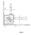
- FIG. 2 shows an exemplary embodiment of such a detector 10, which is arranged in a corner of a monitored room and with the two reception areas E3 and E4 of which two walls 11 and 12 of the room provided with windows or doors can be monitored for intrusion attempts.
- the two reception areas must form a horizontal angle of 90 ° with one another.
- This is achieved by providing a dual sensor 2 with two sensor elements 3 and 4 in the housing 1, as in the first example described, which are connected to a circuit 7.
- two Fresnel cylindrical lenses 81 and 82 are provided on different, abutting sides of the housing 1.
- Both fres nel cylindrical lenses are in turn curved in a circle with a radius of curvature corresponding to their focal length, both focal lengths being able to be chosen the same, but can also be different for special applications, such as rectangular spaces, with considerably different side lengths.
- the arrangement of the two lenses is such that one sensor element 3 lies in the focal point of one lens 81 and the other sensor element 4 lies in the focal point of the other lens 4.
- the one sensor element 3 thereby receives radiation from the one receiving area E3, while the other sensor element 4 receives radiation from the other reception area E4.
- a radiation entry window 9 is provided in front of the sensor elements 3 and 4.
Abstract
Description
Die Erfindung betrifft einen Infrarot-Eindringdetektor gemäß dem Oberbegriff des Patentanspruchs 1.The invention relates to an infrared intrusion detector according to the preamble of
Solche Eindringdetektoren sind beispielsweise aus der US-A-4ʹ058ʹ726 oder DE-C-26ʹ45ʹ040 bekannt. Bei dem in Figur 4 dieser Patentschriften dargestellten Einbruchdetektor wird je ein streifenförmiger Empfangsbereich mittels je einer dem Sensor vorgesetzten Zylinderlinse erzeugt. Damit lässt sich ein überwachter Raum auf einfache Weise mit einer Anzahl vertikal orientierter, parallel streifenförmiger Empfangsbereiche überdecken, bei deren Durchschreitung durch einen Einbrecher mit grosser Sicherheit ein Alarmsignal ausgelöst wird.Such intrusion detectors are known for example from US-A-4ʹ058ʹ726 or DE-C-26ʹ45ʹ040. In the intrusion detector shown in FIG. 4 of these patents, a strip-shaped reception area is generated by means of a cylindrical lens placed in front of the sensor. In this way, a monitored room can be covered in a simple manner with a number of vertically oriented, parallel strip-shaped reception areas which, when passed through, a burglar will most certainly trigger an alarm signal.
Für die Erzeugung eines einzelnen oder weniger eng benachbarten Empfangsbereiche mit flächenhafter Ausdehnung und genau definierten Grenzen, wie sie insbesondere zur Verwendung als Schutzvorhang vor Oeffnungen, wie Türen oder Fenster, oder auch als flächenhafte Schranken vor geschützten Objekten benötigt werden, genügen solche vorbekannte Anordnungen jedoch nur beschränkt. Zunächst ist der vertikale Oeffnungswinkel durch das Gehäuse begrenzt und erreicht praktisch nie, wie bei einem voll wirksamen Schutzvorhang erforderlich, nahezu 90°.However, such previously known arrangements are only sufficient for the creation of a single or less closely adjacent reception area with extensive expansion and precisely defined boundaries, such as are required in particular for use as a protective curtain against openings, such as doors or windows, or also as flat barriers in front of protected objects limited. First of all, the vertical opening angle is limited by the housing and practically never reaches almost 90 °, as is required with a fully effective protective curtain.
Ausserdem ist hierbei nur in der Mitte der Zylinderlinsen eine gute Fokussierung gewährleistet, da nur dort der Sensor in der Brennlinie liegt. Für schräg einfallende Strahlen liegt dagegen der Sensor ausserhalb der Brennlinie, so dass dafür keine einwandfreie Abbildung mehr stattfindet. Die Folge ist, dass die Empfangsbereichsgrenzen bei schrägem Strahlungseinfall unscharf sind, und im Extremfall benachbarte Empfangsbereiche ineinander übergehen, so dass hier kein wirksamer Schutz mehr möglich ist. Ausserdem ist nachteilig, dass die optische Weglänge innerhalb der Zylinderlinse mit zunehmendem Neigungswinkel zunimmt. Bei nicht zu vernachlässigender Absorption des Linsenmaterials im fernen Infarot, z.B. bei etwa 10 um, wo die Körperstrahlung eines Menschen ihr Maximum besitzt, ist die Strahlungsschwächung also um so grösser, je schräger die Strahlung einfällt. Ein solcher Einbruchdetektor wird immer unempfindlicher, und ist auch aus diesem Grunde zur Verwendung als Schutzvorhang mit grossem Oeffnungswinkel nur beschränkt brauchbar.In addition, good focusing is only guaranteed in the middle of the cylindrical lenses, since only there is the sensor in the focal line. For obliquely incident rays, on the other hand, the sensor is outside the focal line, so that there is no longer a perfect image. The result is that the reception area limits are blurred in the case of oblique radiation incidence, and in extreme cases neighboring reception areas merge into one another, so that effective protection is no longer possible here. In addition, it is disadvantageous that the optical path length within the cylindrical lens increases with an increasing angle of inclination. If the lens material in the far infrared is not negligible, for example at about 10 μm, where the body radiation of a person has its maximum, the radiation attenuation is greater the more obliquely the radiation is incident. Such a burglar detector is becoming less and less sensitive and, for this reason too, is of limited use for use as a protective curtain with a large opening angle.
Bei dem in US-A-4ʹ375ʹ034 beschriebenem Infrarot-Eindringdetektor wird zur Erzeugung eines oder mehrerer Empfangsbereiche mit schärferen Grenzen und vergrössertem Oeffnungwinkel ein sphärischer Reflektor mit einem oder mehreren zylindrischen Reflektoren in bestimmter Weise kombiniert. Dies erfordert eine komplizierte optische Anordnung, bei der die einzelnen Reflektoren genau zueinander justiert werden müssen, und wobei diese Justierung über die gesamte Betriebszeit, d.h. über Jahre hinaus aufrechterhalten werden muss. Ausserdem unterliegen die Reflektor-Oberflächen der Alterung und einer langsamen Verstaubung, d.h. einer progressiven Verminderung des Reflexionsvermögens und zunehmender Strahlungs-Streuung, so dass die Empfindlichkeit, Wirksamkeit und Betriebssicherheit solcher Detektoren allmählich abnimmt.In the infrared intrusion detector described in US-A-4,375,034, a spherical reflector is combined in a certain way with one or more cylindrical reflectors in order to produce one or more reception areas with sharper limits and an enlarged opening angle. This requires a complicated optical arrangement in which the individual reflectors have to be adjusted exactly to one another, and this adjustment over the entire operating time, i.e. must be maintained for years to come. In addition, the reflector surfaces are subject to aging and slow dusting, i.e. a progressive reduction in reflectivity and increasing radiation scatter, so that the sensitivity, effectiveness and operational safety of such detectors gradually decrease.
In der US-A-4ʹ321ʹ594 ist ein passiver Infrarot-Eindring-Detektor beschrieben, bei dem eine oder mehrere Fresnel-Linsen mit konzentrischer Anordnung der Linsensegmente zur Fokussierung von Infrarot-Strahlung auf ein Detektorelement dienen. Gemäss einer Ausführungsform können auch mehrere konzentrische Fresnel-Linsen vorhanden sein, welche um einen breiteren Ueberwachungsraum abzudecken, zylindrisch gebogen sind und die Infrarot-Strahlung auf ein Detektorelement fokussieren. Damit der Detektor wirksam arbeiten kann ist es erforderlich, dass der Eindringling mehrere streifenförmige Empfangsbereiche durchschreitet.US Pat. No. 4,332,594 describes a passive infrared penetration detector in which one or more Fresnel lenses with a concentric arrangement of the lens segments serve to focus infrared radiation onto a detector element. According to one embodiment, a plurality of concentric Fresnel lenses can also be present, which are cylindrically curved to cover a wider monitoring area and focus the infrared radiation on a detector element. In order for the detector to work effectively, it is necessary for the intruder to pass through several strip-shaped reception areas.
Aus der UK-A-2ʹ122ʹ339 ist ein passiver Infrarot-Eindring-Detek tor bekannt, welcher mehrere Fresnel-Linsen aufweist. Dabei sind recht eckige Ausschnitte aus Fresnel-Linsen mit konzentrischer Anordnung der Linsensegmente in D-Form so angeordnet, dass die von ihnen aufgenommene Infrarot-Strahlung auf einen Infrarot-Detektor fokussiert wird. Auch dieser Detektor dient zur Ueberwachung von Räumen, wobei eine Wirksamkeit nur eintreten kann, wenn der Eindringling mehrere streifenförmige Empfangsbereiche durchschreitet. Eine lückenlose Ueberwachung eines schmalen Bereichs zur Absicherung beispielsweise von Wandöffnungen ist weder mit diesem Detektor noch mit dem Detektor gemäss US-A-4ʹ321ʹ594 möglich.UK-A-2ʹ122ʹ339 is a passive infrared intrusion detector Tor known, which has several Fresnel lenses. Rectangular sections of Fresnel lenses with a concentric arrangement of the lens segments in D-shape are arranged so that the infrared radiation they pick up is focused on an infrared detector. This detector is also used to monitor rooms, and effectiveness can only occur if the intruder passes through several strip-shaped reception areas. A continuous monitoring of a narrow area to secure wall openings, for example, is not possible with this detector or with the detector according to US Pat. No. 4,321,594.
Um die erwähnten Nachteile des Standes der Technik zu beseitigen, setzt sich die Erfindung die Aufgabe, einen Infrarot-Eindringdetektor zu schaffen, der speziell zur Bildung eines Schutzvorhanges mit wenigstens einem streifenförmigen Empfangsbereich mit grossem Oeffnungswinkel, scharfen Bereichsgrenzen und gleichbleibender Strahlungsempfindlichkeit über die ganze Oeffnung geeignet ist, und zwar mittels einer geringen Anzahl von optischen Elementen in einer einfachen, störungsunanfälligen Anordnung, wobei die Empfindlichkeit, Wirksamkeit und Betriebssicherheit auch über längere Zeiten erhalten bleibt.In order to eliminate the disadvantages of the prior art mentioned, the invention sets itself the task of creating an infrared intrusion detector which is particularly suitable for forming a protective curtain with at least one strip-shaped reception area with a large opening angle, sharp area boundaries and constant radiation sensitivity over the entire opening is, and that by means of a small number of optical elements in a simple, interference-free arrangement, the sensitivity, effectiveness and operational safety is maintained even over long periods.
Diese Aufgabe wird bei einem Infrarot-Eindringdetektor der eingangs gennannten Art durch die kennzeichnenden Merkmale des Patentanspruchs 1 gelöst. Bevorzugte Ausführungsformen der Erfindung und Ausgestaltungen sind in den abhängigen Patentansprüchen definiert.This object is achieved in an infrared intrusion detector of the type mentioned by the characterizing features of
Mit den genannten Merkmalen wird erreicht, dass die Güte der optischen Abbildung und damit die Schärfe der Empfangsbereichsgrenzen, sowie die Strahlungsabsorption und somit die Empfindlichkeit des Detektors vom Strahlungseinfallwinkel unabhängig wird, so dass ein solcher Detektor mit besonderem Vorteil zur Bildung eines flächenhaften Schutzvorhanges mit grossem Oeffnungswinkel geeignet ist. Zudem wird nur ein einziges, leicht montierbares optisches Element benötigt.With the features mentioned it is achieved that the quality of the optical image and thus the sharpness of the reception area limits, as well as the radiation absorption and thus the sensitivity of the detector, is independent of the angle of incidence of radiation, so that such a detector is particularly advantageous for forming a flat protective curtain with a large opening angle suitable is. In addition, only a single, easily mountable optical element is required.
Mit Vorteil kann der Infrarot-Sensor als Dual-Sensor mit zwei benachbarten Sensorelementen in einer Differenzschaltung ausgebildet sein, womit sich mit einer kreisförmig gebogenen Fresnel-Linse ein Doppelvorhang mit zwei Empfangsbereichen und eine besonders störsichere und selektive Detektion eines Einbruchversuches erreichen lässt.The infrared sensor can advantageously be designed as a dual sensor with two adjacent sensor elements in a differential circuit, with which a double curtain with two reception areas and particularly interference-free and selective detection of an attempted break-in can be achieved with a circularly curved Fresnel lens.
Weitere bevorzugte Ausführungsformen der Erfindung und Ausgestaltungen sind in den abhängigen Patentansprüchen definiert.Further preferred embodiments of the invention and refinements are defined in the dependent patent claims.
Die Erfindung wird an Hand der in den Figuren dargestellten Ausführungsbeispielen von Infrarot-Eindringdetektoren näher erläutert. Es zeigen:
Figur 1 einen ersten Eindringdetektor in perspektivischer Darstellung,Figur 2 eine bevorzugte Ausführungsform eines Eindringdetektors mit mehreren Fresnel-Zylinderlinsen im Horizontal-Schnitt, sowie seine räumliche Anordnung,
- FIG. 1 shows a first penetration detector in a perspective view,
- FIG. 2 shows a preferred embodiment of an intrusion detector with several Fresnel cylindrical lenses in horizontal section, and its spatial arrangement,
Bei dem in Figur 1 gezeigten Infrarot-Eindringdetektor ist in einem Gehäuse 1 ein Infrarot-Sensor 2 angeordnet, der vorzugsweise für den Wellenlängenbereich der Körperstrahlung eines Menschen empfindlich ist, z.B. im Gebiet um 10 µm, bzw. im Bereich von etwa 5 - 10 um, und der z.B. als pyroelektrischer Sensor ausgeführt sein kann. Der Sensor kann als einfacher Sensor mit nur einer Zone zum Strahlungsempfang ausgebildet sein, wenn nur die Bildung eines einzigen Empfangsbereiches als Schutzvorhang gewünscht wird, oder aber, wie in der Figur dargestellt, als Dual-Sensor mit zwei benachbarten Sensorelementen 3, 4, die zwei entsprechende, dicht benachbarte Empfangsbereiche E3, E4 als Schutzvorhänge erzeugenIn the infrared penetration detector shown in Figure 1, an
Zu diesem Zweck ist an der Vorderseite des Gehäuses 1 eine optische Anordnung 8 vorgesehen. Diese ist als Fresnel-Zylinderlinse ausgebildet. In Querrichtung, die bei der praktischen Verwendung vorzugsweise horizontal orientiert ist, hat diese Linse 8 die charakteristische Struktur einer Fresnel-Linse bestimmter Brennweite, d.h. eine Vielzahl von in Längsrichtung verlaufender parallelen Furchen 5, wobei die optische Dicke der Linse über die gesamte Breite unterhalb einer bestimmten Maximaldichte d liegt. In Längsrichtung, in der Praxis meist vertikal orientiert, findet dagegen keine Fokussierung statt, d.h. die Linse 8 hat die Wirkung einer Zylinderlinse mit Fokussierung nur in der Querrichtung, jedoch ohne Bündelung oder sonstige Strahlungs-Ablenkung in Längsrichtung.For this purpose, an
Durch diese Ausbildung der Linse 8 als Fresnel-Zylinderlinse mit gleichmässig kleiner Dicke in Längs- und Querrichtung erhält diese eine bei normalen massiven Linsen nicht erreichbare Flexibilität und Biegsamkeit. Diese macht es möglich, die Fresnel-Zylinderlinse zu einem Teilkreis gebogen an der Vorderseite des Gehäuses 1 anzubringen, wobei, wie in diesem Ausführungsbeispiel dargestellt, die Mitte der Linse 8 über die Gehäuse-Vorderseite hinausragen und die offenen Seiten beidseits durch Blenden 6 verschlossen sein können. Der Krümmungsradius r der Linse 8 ist so gewählt, dass er möglichst gut ihrer Brennweite in Querrichtung entspricht, und der Sensor 2 ist wenigstens angenähert im Kreismittelpunkt und damit auch im Brennpunkt angeordnet, so dass der Abstand des Sensors 2 von der Linse 8 überall, d.h. unabhängig vom Einfallswinkel der Strahlung, und sowohl in der Mttte als auch am Rand der Linse und des Gehäuses wenigstens angenähert gleich ist und der Brennweite in Querrichtung entspricht. Um eine optimale Wirkung zu erzielen, sollte also die Krümmung der Frensel-Zylinderlinse 8 in Längsrichtung so gewählt werden, dass der Krümmungsradius r möglichst gut der Brennweite in Querrichtung entspricht und der Sensor sollte möglichst gut im Mittelpunkt plaziert sein.This configuration of the
Mit diesen Merkmalen wird erreicht, dass die Güte der optischen Abbildung für alle Einstrahlungswinkel und über die ganze ausnützbare Vertikalöffnung gleich ist. Die damit erzeugten Empfangsbereiche sind alo über die gesamte Oeffnung gleich scharf begrenzt und erlauben die Bildung eines Schutzvorhanges mit gleichmässier Empfindlichkeit über die gesamte Oeffnung. Hinzu kommt, dass die Durchstrahlungslänge der Linse ebenfalls vom Ein fallswinkel unabhängig wird, und somit auch die mögliche Strahlungs-Absorption, so dass auch hierdurch keine Empfindlichkeits-Abnahme mit zunehmendem Einfallswinkel eintreten kann. Ausserdem lässt die Wölbung der Fresnel-Linse eine geringere Gehäusetiefe zu und macht es möglich, den Senor näher zur Vorderseite des Gehäuses zu plazieren, so dass dadurch ausnützbare Oeffnungswinkel bis zu 90° möglich werden. Dabei werden diese Vorteile auf einfachste Weise mit einem einzigen, unempfindlichen und leicht montierbaren optischen Element erreicht.With these features it is achieved that the quality of the optical image is the same for all angles of incidence and over the entire usable vertical opening. The reception areas thus generated are equally sharply delimited across the entire opening and allow the formation of a protective curtain with uniform sensitivity over the entire opening. In addition, the radiation length of the lens is also from the on angle of fall becomes independent, and thus also the possible radiation absorption, so that no decrease in sensitivity with increasing angle of incidence can also occur as a result. In addition, the curvature of the Fresnel lens permits a smaller housing depth and makes it possible to place the sensor closer to the front of the housing, so that usable opening angles of up to 90 ° are possible. These advantages are achieved in the simplest way with a single, insensitive and easily mountable optical element.
Es sei erwähnt, dass die beschriebene Detektor-Anordnung auch mit einem Einzel-Sensor versehen sein kann, wobei nur ein einziger Empfangsbereich oder Schutzvorhang gebildet wird. Die Auswertung des Sensor-Ausgangssignales kann dabei in bekannter Weise, wie z.B. in US-A-3ʹ703ʹ718 beschrieben, erfolgen. Bei Verwendung eines Dual-Sensors mit zwei Senorelementen, die einen Doppelvorhang mit zwei dicht benachbarten Empfangsbereichen bilden, können diese mit Vorteil an eine Differenz-Schaltung 7 angeschlossen sein, die wiederum mit einer bekannten, besonders selektiv arbeitenden Auswerteschaltung, z.B. nach US-A-4ʹ339ʹ748 verbunden ist.It should be mentioned that the detector arrangement described can also be provided with a single sensor, with only a single reception area or protective curtain being formed. The evaluation of the sensor output signal can be done in a known manner, e.g. described in US-A-3ʹ703ʹ718. When using a dual sensor with two sensor elements, which form a double curtain with two closely adjacent reception areas, these can advantageously be connected to a
Falls erwünscht, können auch mehrere Fresnel-Zylinderlinsen in demselben Gehäuse vorgesehen sein, um eine grössere Anzahl von Empfangsbereichen gleichzeitig überwachen zu können.If desired, several Fresnel cylindrical lenses can also be provided in the same housing in order to be able to monitor a larger number of reception areas at the same time.
Die Figur 2 zeigt ein Ausführungsbeispiel eines derartigen Detektors 10, der in einer Ecke eines überwachten Raumes angeordnet ist, und mit dessen beiden Empfangsbereichen E3 und E4 gleichzeitig zwei mit Fenstern oder Türen versehene Wände 11 und 12 des Raumes auf Eindringversuche überwacht werden können. Dazu müssen die beiden Empfangsbereiche etwa einen Horizontal-Winkel von 90° miteinander bilden. Dies wird dadurch erreicht, dass im Gehäuse 1, wie im erstbebeschriebenen Beispiel, ein Dual-Sensor 2 mit zwei Sensorelementen 3 und 4 vorgesehen ist, die an eine Schaltung 7 angeschlossen sind. Statt einer einzigen Fresnel-Linse sind hier jedoch zwei Fresnel-Zylinderlinsen 81 und 82 an verschiedenen, aneinanderstossenden Seiten des Gehäuses 1 vorgesehen. Beide Fres nel-Zylinderlinsen sind wiederum kreisförmig mit einem Krümmungsradius entsprechend ihrer Brennweite gebogen, wobei beide Brennweiten gleich gewählt sein können, für spezielle Anwendungen, wie rechteckige Räume, mit erheblich unterschiedlichen Seitenlängen, aber auch verschieden sein können. Die Anordnung der beiden Linsen ist dabei so getroffen, dass das eine Sensorelement 3 im Brennpunkt der einen Linse 81 liegt, und das andere Sensorelement 4 im Brennpunkt der anderen Linse 4. Das eine Sensorelement 3 erhält dadurch Strahlung aus dem einen Empfangsbereich E3, während das andere Sensorelement 4 Strahlung aus dem anderen Empfangsbereich E4 aufnimmt. Um Strahlung aus dem nicht-zugehörigen Empfangsbereich von den Sensorelementen abzuschatten, ist vor den Sensorelementen 3 und 4 ein Strahlungseintrittsfenster 9 vorgesehen. Auf diese Weise ist es möglich, mit einem Detektor gleichzeitig zwei Wandfronten eines Raumes, die einen Winkel von ca. 90° miteinander bilden, zu überwachen. Dabei kann eine gewisse Flexibilität und eine Einstellbarkeit des Winkels zwischen den beiden Empfangsbereichen dadurch erreicht werden, dass die beiden Fresnel-Zylinderlinsen 81 und 82 in Horizontalrichtung auf Kreisbögen 13, 14 an den Gehäuseseiten schwenkbar sind, wobei sich die Sensorelemente 3, 4 im Mittelpunkt des zugehörigen Kreisbogen befinden.FIG. 2 shows an exemplary embodiment of such a
Abwandlungen des Infrarot-Eindringdetektors sind im Rahmen der Erfindung gemäss den Patentansprüchen möglich und dem Fachmann geläufig.Modifications of the infrared penetration detector are possible within the scope of the invention according to the patent claims and are familiar to the person skilled in the art.
-
Gehäuse 1
Housing 1 -
Infrarot-Sensor 2
Infrared sensor 2 -
Sensor-Element 3
Sensor element 3 -
Sensor-Element 4
Sensor element 4 -
Furchen 5
Furrows 5 -
Blenden 6
Apertures 6 -
Auswerteschaltung 7
Evaluation circuit 7 -
Optische Anordnung 8
Optical arrangement 8 -
Detektor 10
Detector 10 -
Wand 11
Wall 11 -
Wand 12
Wall 12 -
Kreisbogen 13
Circular arc 13 -
Kreisbogen 14
Arc 14 -
Fresnel-Zylinderlinse 81Fresnel
cylindrical lens 81 -
Fresnel-Zylinderlinse 82Fresnel
cylindrical lens 82 - Maximaldicke dMaximum thickness d
- Krümmungsradius rRadius of curvature r
- Empfangsbereich E3Reception area E3
- Empfangsbereich E4Reception area E4
Claims (10)
Priority Applications (2)
| Application Number | Priority Date | Filing Date | Title |
|---|---|---|---|
| DE19853518262 DE3518262A1 (en) | 1985-05-21 | 1985-05-21 | Infrared intrusion detector |
| EP86113451A EP0262241A1 (en) | 1986-10-01 | 1986-10-01 | Infra-red intrusion detector |
Applications Claiming Priority (1)
| Application Number | Priority Date | Filing Date | Title |
|---|---|---|---|
| EP86113451A EP0262241A1 (en) | 1986-10-01 | 1986-10-01 | Infra-red intrusion detector |
Publications (1)
| Publication Number | Publication Date |
|---|---|
| EP0262241A1 true EP0262241A1 (en) | 1988-04-06 |
Family
ID=8195460
Family Applications (1)
| Application Number | Title | Priority Date | Filing Date |
|---|---|---|---|
| EP86113451A Withdrawn EP0262241A1 (en) | 1985-05-21 | 1986-10-01 | Infra-red intrusion detector |
Country Status (1)
| Country | Link |
|---|---|
| EP (1) | EP0262241A1 (en) |
Cited By (5)
| Publication number | Priority date | Publication date | Assignee | Title |
|---|---|---|---|---|
| FR2710172A1 (en) * | 1993-09-14 | 1995-03-24 | Ind Entreprise | Device for infrared detection of the crossing of a boundary which is physically represented by two parallel planes |
| DE19532680A1 (en) * | 1995-09-05 | 1997-03-06 | Telefunken Microelectron | Optical system |
| CN108550231A (en) * | 2018-06-22 | 2018-09-18 | 深圳市全智芯科技有限公司 | A kind of inductor and its induction system |
| CN110276887A (en) * | 2018-03-13 | 2019-09-24 | 浙江星星冷链集成股份有限公司 | A kind of self-service cabinet with far infrared pyroelectric sensing function |
| CN110823887A (en) * | 2018-08-09 | 2020-02-21 | Bcs汽车接口解决方案有限公司 | Optical assembly and method of manufacturing optical assembly |
Citations (3)
| Publication number | Priority date | Publication date | Assignee | Title |
|---|---|---|---|---|
| US4321594A (en) * | 1979-11-01 | 1982-03-23 | American District Telegraph Company | Passive infrared detector |
| GB2122339A (en) * | 1982-06-25 | 1984-01-11 | John Anthony Bloice | Infra-red intrusion detector system |
| DE3235250A1 (en) * | 1982-09-23 | 1984-03-29 | Heimann Gmbh, 6200 Wiesbaden | Facetted optical system for detecting radiation from a large solid angle, in particular for motion detectors |
-
1986
- 1986-10-01 EP EP86113451A patent/EP0262241A1/en not_active Withdrawn
Patent Citations (3)
| Publication number | Priority date | Publication date | Assignee | Title |
|---|---|---|---|---|
| US4321594A (en) * | 1979-11-01 | 1982-03-23 | American District Telegraph Company | Passive infrared detector |
| GB2122339A (en) * | 1982-06-25 | 1984-01-11 | John Anthony Bloice | Infra-red intrusion detector system |
| DE3235250A1 (en) * | 1982-09-23 | 1984-03-29 | Heimann Gmbh, 6200 Wiesbaden | Facetted optical system for detecting radiation from a large solid angle, in particular for motion detectors |
Cited By (6)
| Publication number | Priority date | Publication date | Assignee | Title |
|---|---|---|---|---|
| FR2710172A1 (en) * | 1993-09-14 | 1995-03-24 | Ind Entreprise | Device for infrared detection of the crossing of a boundary which is physically represented by two parallel planes |
| DE19532680A1 (en) * | 1995-09-05 | 1997-03-06 | Telefunken Microelectron | Optical system |
| US5710671A (en) * | 1995-09-05 | 1998-01-20 | Temic Telefunken Microelectronic Gmbh | Optical system |
| CN110276887A (en) * | 2018-03-13 | 2019-09-24 | 浙江星星冷链集成股份有限公司 | A kind of self-service cabinet with far infrared pyroelectric sensing function |
| CN108550231A (en) * | 2018-06-22 | 2018-09-18 | 深圳市全智芯科技有限公司 | A kind of inductor and its induction system |
| CN110823887A (en) * | 2018-08-09 | 2020-02-21 | Bcs汽车接口解决方案有限公司 | Optical assembly and method of manufacturing optical assembly |
Similar Documents
| Publication | Publication Date | Title |
|---|---|---|
| DE2653111C3 (en) | Infrared Radiation Intrusion Detector | |
| DE2653110C3 (en) | Infrared Radiation Intrusion Detector | |
| DE19628050C2 (en) | Infrared measuring device and method of detecting a human body through it | |
| EP0652422B1 (en) | Device for receiving light rays | |
| DE3129753A1 (en) | PASSIVE INFRARED ROOM PROTECTION DEVICE | |
| DE2537380B2 (en) | Monitoring device with a group of radiation detector elements | |
| EP0328709B1 (en) | Light barrier | |
| DE2103909A1 (en) | Monitoring device to determine the presence of an intruder in a room | |
| DE2904654A1 (en) | OPTICAL ARRANGEMENT FOR A PASSIVE INFRARED MOTION DETECTOR | |
| EP0050751A1 (en) | Optical arrangement for an infrared intrusion detector | |
| EP0323601A2 (en) | Radiation detector | |
| EP0189536A1 (en) | Infrared intrusion detector | |
| DE3128073C2 (en) | Alarm indicator for securing a passage or a passage section | |
| CH676642A5 (en) | ||
| CH667744A5 (en) | INFRARED INTRUSION DETECTOR. | |
| EP0821330B1 (en) | Smoke detector | |
| DE19848272B4 (en) | Passive infrared detector | |
| EP0191155A1 (en) | Infrared intrusion detector | |
| CH657928A5 (en) | ARRANGEMENT FOR A RADIATION DETECTOR WITH SEVERAL SENSOR ELEMENTS AND THEIR USE. | |
| CH651941A5 (en) | Optical arrangement for a radiation detector. | |
| EP0262241A1 (en) | Infra-red intrusion detector | |
| DE2645040C3 (en) | Radiation detector | |
| DE3518262C2 (en) | ||
| EP0050750B1 (en) | Infrared intrusion detector | |
| DE3500860A1 (en) | Optical arrangement on passive infrared motion detectors |
Legal Events
| Date | Code | Title | Description |
|---|---|---|---|
| PUAI | Public reference made under article 153(3) epc to a published international application that has entered the european phase |
Free format text: ORIGINAL CODE: 0009012 |
|
| 17P | Request for examination filed |
Effective date: 19861001 |
|
| AK | Designated contracting states |
Kind code of ref document: A1 Designated state(s): DE ES FR GB IT NL |
|
| 17Q | First examination report despatched |
Effective date: 19880714 |
|
| ITF | It: translation for a ep patent filed |
Owner name: RIT.TO ALL'OEB ALLO STATO DI DOMANDA;VETTOR GALLET |
|
| STAA | Information on the status of an ep patent application or granted ep patent |
Free format text: STATUS: THE APPLICATION IS DEEMED TO BE WITHDRAWN |
|
| 18D | Application deemed to be withdrawn |
Effective date: 19901218 |
|
| RIN1 | Information on inventor provided before grant (corrected) |
Inventor name: MEIER, WALTER Inventor name: WUETHRICH, ALFRED |