EP0261906A2 - Spring-loaded hinge assembly for vehicle accessories - Google Patents
Spring-loaded hinge assembly for vehicle accessories Download PDFInfo
- Publication number
- EP0261906A2 EP0261906A2 EP87308324A EP87308324A EP0261906A2 EP 0261906 A2 EP0261906 A2 EP 0261906A2 EP 87308324 A EP87308324 A EP 87308324A EP 87308324 A EP87308324 A EP 87308324A EP 0261906 A2 EP0261906 A2 EP 0261906A2
- Authority
- EP
- European Patent Office
- Prior art keywords
- cam
- hinge assembly
- resilient biasing
- vanity
- biasing means
- Prior art date
- Legal status (The legal status is an assumption and is not a legal conclusion. Google has not performed a legal analysis and makes no representation as to the accuracy of the status listed.)
- Withdrawn
Links
Images


Classifications
-
- B—PERFORMING OPERATIONS; TRANSPORTING
- B60—VEHICLES IN GENERAL
- B60J—WINDOWS, WINDSCREENS, NON-FIXED ROOFS, DOORS, OR SIMILAR DEVICES FOR VEHICLES; REMOVABLE EXTERNAL PROTECTIVE COVERINGS SPECIALLY ADAPTED FOR VEHICLES
- B60J3/00—Antiglare equipment associated with windows or windscreens; Sun visors for vehicles
- B60J3/02—Antiglare equipment associated with windows or windscreens; Sun visors for vehicles adjustable in position
- B60J3/0204—Sun visors
- B60J3/0278—Sun visors structure of the body
- B60J3/0282—Sun visors structure of the body specially adapted for a courtesy mirror
-
- E—FIXED CONSTRUCTIONS
- E05—LOCKS; KEYS; WINDOW OR DOOR FITTINGS; SAFES
- E05D—HINGES OR SUSPENSION DEVICES FOR DOORS, WINDOWS OR WINGS
- E05D11/00—Additional features or accessories of hinges
- E05D11/10—Devices for preventing movement between relatively-movable hinge parts
- E05D11/1028—Devices for preventing movement between relatively-movable hinge parts for maintaining the hinge in two or more positions, e.g. intermediate or fully open
- E05D11/105—Devices for preventing movement between relatively-movable hinge parts for maintaining the hinge in two or more positions, e.g. intermediate or fully open the maintaining means acting perpendicularly to the pivot axis
-
- E—FIXED CONSTRUCTIONS
- E05—LOCKS; KEYS; WINDOW OR DOOR FITTINGS; SAFES
- E05D—HINGES OR SUSPENSION DEVICES FOR DOORS, WINDOWS OR WINGS
- E05D7/00—Hinges or pivots of special construction
- E05D7/10—Hinges or pivots of special construction to allow easy separation or connection of the parts at the hinge axis
- E05D7/1061—Hinges or pivots of special construction to allow easy separation or connection of the parts at the hinge axis in a radial direction
- E05D7/1077—Hinges or pivots of special construction to allow easy separation or connection of the parts at the hinge axis in a radial direction with snap-fitted pins
-
- E—FIXED CONSTRUCTIONS
- E05—LOCKS; KEYS; WINDOW OR DOOR FITTINGS; SAFES
- E05D—HINGES OR SUSPENSION DEVICES FOR DOORS, WINDOWS OR WINGS
- E05D5/00—Construction of single parts, e.g. the parts for attachment
- E05D5/10—Pins, sockets or sleeves; Removable pins
- E05D5/14—Construction of sockets or sleeves
- E05D2005/145—Construction of sockets or sleeves with elastically deformable parts
-
- E—FIXED CONSTRUCTIONS
- E05—LOCKS; KEYS; WINDOW OR DOOR FITTINGS; SAFES
- E05F—DEVICES FOR MOVING WINGS INTO OPEN OR CLOSED POSITION; CHECKS FOR WINGS; WING FITTINGS NOT OTHERWISE PROVIDED FOR, CONCERNED WITH THE FUNCTIONING OF THE WING
- E05F1/00—Closers or openers for wings, not otherwise provided for in this subclass
- E05F1/08—Closers or openers for wings, not otherwise provided for in this subclass spring-actuated, e.g. for horizontally sliding wings
- E05F1/10—Closers or openers for wings, not otherwise provided for in this subclass spring-actuated, e.g. for horizontally sliding wings for swinging wings, e.g. counterbalance
- E05F1/12—Mechanisms in the shape of hinges or pivots, operated by springs
- E05F1/1284—Mechanisms in the shape of hinges or pivots, operated by springs with a leaf or similar spring
-
- E—FIXED CONSTRUCTIONS
- E05—LOCKS; KEYS; WINDOW OR DOOR FITTINGS; SAFES
- E05Y—INDEXING SCHEME RELATING TO HINGES OR OTHER SUSPENSION DEVICES FOR DOORS, WINDOWS OR WINGS AND DEVICES FOR MOVING WINGS INTO OPEN OR CLOSED POSITION, CHECKS FOR WINGS AND WING FITTINGS NOT OTHERWISE PROVIDED FOR, CONCERNED WITH THE FUNCTIONING OF THE WING
- E05Y2900/00—Application of doors, windows, wings or fittings thereof
- E05Y2900/20—Application of doors, windows, wings or fittings thereof for furnitures, e.g. cabinets
-
- E—FIXED CONSTRUCTIONS
- E05—LOCKS; KEYS; WINDOW OR DOOR FITTINGS; SAFES
- E05Y—INDEXING SCHEME RELATING TO HINGES OR OTHER SUSPENSION DEVICES FOR DOORS, WINDOWS OR WINGS AND DEVICES FOR MOVING WINGS INTO OPEN OR CLOSED POSITION, CHECKS FOR WINGS AND WING FITTINGS NOT OTHERWISE PROVIDED FOR, CONCERNED WITH THE FUNCTIONING OF THE WING
- E05Y2900/00—Application of doors, windows, wings or fittings thereof
- E05Y2900/50—Application of doors, windows, wings or fittings thereof for vehicles
- E05Y2900/53—Application of doors, windows, wings or fittings thereof for vehicles characterised by the type of wing
- E05Y2900/538—Interior lids
Definitions
- the present invention relates generally to hinge assemblies for hinged or pivotally interconnected members, and more particularly to such hinge assemblies especially adapted for pivotally interconnecting a vehicle accessory door with a vehicle accessory housing structure or other portion of the interior of a vehicle.
- vehicle accessory doors include vanity doors, storage compartment doors or other accessory covers.
- Hinge assemblies according to the present invention can also be employed for various non-vehicular uses, as will be readily appreciated by one skilled in the art from the following discussion.
- the typical vehicle includes a wide variety of hinged or pivotally mounted vehicle accessories or accessory covers in the interior, luggage storage areas, engine compartment, or other areas.
- many hinge assemblies for such vehicular applications, as well as those for various non-vehicular applications either have not been sufficiently durable or have been relatively expensive to produce and install.
- many of such prior hinge assemblies have been found to be inordinately bulky, unsightly, or ill-fitting, all of which detract from the user's perception of quality with regard to the vehicle or other device in which such hinge assemblies are included.
- This hinge arrangement does not have a pivot pin or other member pivotally interconnecting the hinged members and thus the spring functions both as a resilient biasing member for resiliently biasing the hinged members toward one another and as a "fastener” for securing the hinged members together.
- These arrangements have been found to have various disadvantages in terms of durability, performance, complexity, or expense of manufacture. The need has therefore arisen for a hinge assembly of the type described herein, which is simple and inexpensive to produce, assemble and install, that is highly durable, and that is capable of maintaining the hinged member in one or more relative rotational or pivotal orientations, such as in open and closed positions, for example.
- a spring-loaded hinge assembly for interconnecting first and second relatively rotatable members in a hinged relationship with respect to one another.
- a hinge assembly includes a pivot pin or other pivot means for pivotally interconnecting the first and second members for relative rotational movement about a generally longitudinally-extending axis and a cam protruding in a generally lateral direction from one of the first or second members for rotational relative movement therewith.
- a spring or other resilient biasing means on the other of the first or second members is slidably engaged and resiliently defected by the cam in order to exert a resilient biasing force on the cam in a generally lateral direction generally toward the longitudinal axis, thus tending to bias the hinged members generally in opposite directions away from one another.
- the resilient biasing means includes a leaf spring secured to one of the first or second members, with the leaf spring being laterally and resiliently deflected by the cam on the other member during at least a portion of the rotational movement of the member.
- the above-mentioned cam has at least one dwell portion thereon for engaging the leaf spring or other resilient biasing means at a corresponding predetermined, relative rotational orientation of the first and second members with respect to one another.
- the resilient biasing means tends to resiliently and releasably maintain the first and second members in the predetermined relative rotational orientation when engaged by the dwell portion of the cam.
- the cam can have at least a pair of the dwell portions thereon, with a laterally-enlarged lobe portion disposed between the dwell portions.
- the dwell portions engage the resilient biasing means at a corresponding pair of predetermined relative rotational orientations of the first and second members, such as in preselected open and closed orientations for example, in order to resiliently and releasably maintain the first and second members in each of the predetermined orientations.
- the resilient biasing means is resiliently and laterally deflected by the cam to a greater extent when engaged by the laterally-enlarged lobe portion of the cam than when engaged by either of the dwell portions of the cam, and the laterally-enlarged lobe portion of the cam has a rounded configuration.
- This preferred arrangement causes the resilient biasing means to tend to forcibly urge or "self-propel" the first and second members into one of the predetermined relative rotational orientations when the resilient biasing means is engaged by the rounded and laterally-enlarged lobe portion of the cam.
- the cam can be disposed on an accessory door for rotational movement therewith relative to an accessory housing structure.
- the leaf spring or other resilient biasing means is disposed on the housing structure for engagement with the cam on the door, as explained above.
- the cam can be disposed on the housing structure, and the leaf spring or other resilient biasing means can be disposed on the accesssory door for rotational movement therewith relative to the housing structure.
- a first movable member is hinged or pivotally interconnected with a fixed or movable second member and is preferably resiliently urged and substantially self-propelled into one of the above-mentioned predetermined rotational orientations relative to the second member whenever the hinged components are moved to relative rotational orientations in close proximity with one of the predetermined relative rotational orientations at which the cam dwell portion or portions engage the leaf spring or other resilient biasing means.
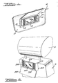
- FIGS 1 through 14 illustrate various embodiments of hinge assemblies according to the present invention, which are shown incorporated in an exemplary application for a vanity door of a vanity assembly on one side of a vehicle sun visor, as well as illustrating a similar vanity assembly for the rear side of a vehicle seat.
- a vanity door of a vanity assembly on one side of a vehicle sun visor
- a similar vanity assembly for the rear side of a vehicle seat.
- FIG. 1 illustrates an exemplary sun visor 12 pivotally interconnected with a pivot rod 14 adapted for mounting in the interior of a vehicle (not shown).
- a vanity assembly 20 is mounted on one side of the sun visor 12 and includes a vanity housing 22 and a hinged vanity door 24 for enclosing a mirror 26 and illumination lights 28, for example.
- a vehicle seat 16 includes a head restraint 18 interconnected therewith, with a vanity assembly 20A mounted on the rear side of the vehicle seat 16.
- the exemplary vanity assembly 20A includes a vanity housing 22A and a hinged vanity door 24A for enclosing a mirror 26A and illumination lights 28A, or other such vehicular accessories.
- the vanity assemblies 20 and 20A shown in Figures 1 and 2, respectively, are merely illustrative examples of suitable applications for one or more hinge assemblies according to the present invention for hingedly or pivotally interconnecting the vanity doors 24 and 24A with the vanity housings 22 and 22A, respectively.
- One preferred embodiment of such a hinge assembly according to the present invention is shown in Figures 3 through 6 and is described in more detail below.
- FIGs 3 through 6 illustrate various detailed views of hinge assembly 30 for hinged or pivotal interconnection of the vanity door 24 with the vanity housing 22, of Figure 1. It should be noted that one or more of the hinge assemblies 30 can also be used for hinged or pivotal interconnection of the vanity door 24A with the vanity housing 22A in Figure 2, as well as in the other vehicular or non-vehicular applications.
- the exemplary hinge assembly 30 includes one or more pivot bearing members 32 interconnected or integrally formed with the vanity door 24 and having open portions 34 for insertion of a pivot rod or pin 50.
- a cam member 36 is also interconnected or integrally formed with the vanity door 24 and includes an open portion 38 for receiving the pivot rod or pin 50 extending longitudinally between the pivot bearing members 32.
- the cam member 36 preferably includes one or more dwell portions 40 and 42 and a lobe portion 44.
- the pivot pin 50 which extends in a generally longitudinal direction, is received within the open portions 34 and 38 of the pivot bearing members 32 and the cam member 36, respectively, in order to hingedly and pivotally interconnect the vanity door 24 and the vanity housing 22.
- the exemplary hinge assembly 30 is preferably composed of a molded synthetic or plastic material, it should be noted that the various components of the hinge assembly 30 can alternately be composed of other suitable materials, and can be constructed by other methods, as will be appreciated by one skilled in the art.
- the single pivot pin 50 shown in the exemplary embodiments of the hinge assembly 30 depicted in the drawings can be replaced by two or more pivot pins, each of which being received in one of the bearing members 32.
- the open portion 38 of the cam member 36 can be eliminated if desired.
- the vanity housing 22 of the preferred exemplary hinge assembly 30 also includes a spring support portion 52, having a spring seat 54 thereon, for receiving and retaining a leaf spring 60 extending in a generally longitudinal direction.
- the leaf spring 60 is generally unsupported in a medial portion between the associated spring seats 54 at opposite ends of the leaf spring 60.
- the deflected leaf spring 60 exerts a resilient biasing force on the cam member 36 in a generally lateral direction, generally toward the longitudinal axis of rotation extending through the pivot pin 50, and thus also tends to resiliently bias the vanity door 24 and the vanity housing 22 in generally opposite directions away from one another.
- the leaf spring 60 functions to resiliently but releasably maintain the vanity door 24 in predetermined rotational orientations relative to the vanity housing 22 when the leaf spring 60 is engaged by the dwell portions 40 and 42 of the cam member 36.
- the laterally-enlarged lobe portion 44 of the cam member 36 preferably has either the narrow intersection of the dwell portions 40 and 42 shown in Figures 5 and 6, or an optional rounded or arcuate shape, confronting the leaf spring 60.
- the resilient biasing force of the leaf spring 60 tends to resiliently and forcibly urge or self-propel the vanity door 20 toward or into one of such predetermined rotational orientations relative to the vanity housing 22 when the leaf spring 60 is engaged by the laterally-enlarged lobe portion 44.
- This effect results primarily from the fact that the leaf spring 60 is preferably resiliently deflected in a lateral direction to a greater extent when engaged by the lobe portion 44 than when engaged by either of the dwell portions 40 or 42.
- the exemplary hinge assembly 30 depicted in the drawings includes the cam member 36 and the pivot bearing members 32 on the vanity door 24, with the pivot pin 50, the leaf spring 60, and the related supporting components on the vanity housing 22, one skilled in the art will readily appreciate that this arrangement can alternately be reversed. In such a reversed arrangement, the cam member 36 and the pivot bearing members 32 would be disposed on the vanity housing 22, while the pivot pin 50, the leaf spring 60, and related supporting components would then be disposed on the vanity door 24. For purposes of convenient reference and simplicity of the drawing figures, such reversed arrangement has not been explicitly shown in the drawings, but the configuration of the hinge components would be substantially identical to that shown in the drawings in connection with the exemplary hinge assembly 30.
- FIGs 7 through 14 illustrate various detailed views of an alternate exemplary hinge assembly 130 for hinged or pivotal interconnection of a vanity door 124 with a vanity housing 122, similar to that shown in Figure 1. It should be noted that one or more of the hinge assemblies 130 can be used for hinged or pivotal interconnection of a vanity door with a vanity housing similar to that shown in Figure 2, as well as in other vehicular or non-vehicular applications.
- the hinge assembly 130 includes one or more pivot bearing members 132 interconnected with the vanity door 124 and having open portions 134 for insertion of a pivot rod or pin (described below).
- a cam member 136 is also interconnected or integrally formed with the vanity door 124 and includes an open portion 138 for receiving a pivot rod or pin extending longitudinally between the pivot bearing members 132.
- the cam member 136 preferably includes one or more dwell portions 140 and 142 and a lobe portion 144.
- the exemplary hinge assembly 130 is preferably composed of a molded synthetic or plastic material, and thus the cam member 136 can optionally be molded with a hollowed configuration, indicated by reference numeral 146. It should be noted that the various components of the hinge assembly 130 can alternately be composed of other suitable materials, and can be constructed by other methods, as will be appreciated by one skilled in the art.
- the vanity housing 122 includes one or more stanchions 148 protruding in a generally lateral direction to support a pivot pin 150, which extends in a generally longitudinal direction.
- the pivot pin 150 is received within the open portions 134 and 138 of the pivot bearing members 132 and the cam member 136, respectively, in order to hingedly and pivotally interconnect the vanity door 124 with the vanity housing 122.
- the pivot pin 150 may be laterally urged and "snapped" into place in a pivotal engagement with the pivot bearing members 132.
- other suitable retaining arrangements can be employed to retain the pivot pin in place in a pivotal engagement with the pivot bearing members 132.
- the single pivot pin 150 shown in the exemplary embodiments of the hinge assembly 130 depicted in the drawings can be replaced by two or more pivot pins, each of which being supported by one or more of the stanchions 148 or other similar pin support arrangements. Where a pair of pivot pins are disposed on opposite sides of the cam member 136 in lieu of the single pivot pin 150 shown in the drawings, the open portion 138 of the cam member 136 can be eliminated if desired.
- the vanity housing 122 of the exemplary hinge assembly 130 also includes a pair of spring support members 152, each of which includes a spring seat 154, and a pair of spring retainers 156 laterally spaced away from the spring seats 154 for receiving and retaining a leaf spring 160 extending generally longitudinally therebetween.
- the leaf spring 160 is generally unsupported in a medial portion between the associated spring support members 152 and spring retainer members 156 at opposite ends of the leaf spring 160.
- the leaf spring 160 is slidably engaged and resiliently deflected by the cam member 136 during pivotal rotational movement of the vanity door 124 relative to the vanity housing 122.
- the deflected leaf spring 160 exerts a resilient biasing force on the cam member 136 in a generally lateral direction, generally toward the longitudinal axis of rotation extending through the pivot pin 150.
- the leaf spring 160 tends to resiliently but releasably maintain the vanity door 124 in predetermined rotational orientations relative to the vanity housing 122 when the leaf spring 160 is engaged by the dwell portions 140 and 142 of the cam member 136.
- the resilient biasing force of the leaf spring 160 tends to resiliently and forcibly urge or self-propel the vanity door 120 into one of such predetermined rotational orientations relative to the vanity housing 122 when the leaf spring 160 is engaged by the laterally-enlarged lobe portion.
- the exemplary hinge assembly 130 depicted in the drawings includes the cam member 136 and the pivot bearing members 132 on the vanity door 124, with the pivot pin 150, the leaf spring 160, and their related supporting components on the vanity housing 122
- this arrangement can alternately be reversed.
- the cam member 136 and the pivot bearing members 132 would be disposed on the vanity housing 122, while the pivot pin 150, the leaf spring 160, and their related components would then be disposed on the vanity door 124.
- such reversed arrangement has not been explicitly shown in the drawings, but the configuration of the hinge components would be substantially identical to that shown in the drawings in connection with the exemplary hinge assembly 130.
Landscapes
- Engineering & Computer Science (AREA)
- Mechanical Engineering (AREA)
- Hinges (AREA)
- Pivots And Pivotal Connections (AREA)
- Closing And Opening Devices For Wings, And Checks For Wings (AREA)
- Hinge Accessories (AREA)
Abstract
Description
- The present invention relates generally to hinge assemblies for hinged or pivotally interconnected members, and more particularly to such hinge assemblies especially adapted for pivotally interconnecting a vehicle accessory door with a vehicle accessory housing structure or other portion of the interior of a vehicle. Such vehicle accessory doors include vanity doors, storage compartment doors or other accessory covers. Hinge assemblies according to the present invention can also be employed for various non-vehicular uses, as will be readily appreciated by one skilled in the art from the following discussion.
- The typical vehicle includes a wide variety of hinged or pivotally mounted vehicle accessories or accessory covers in the interior, luggage storage areas, engine compartment, or other areas. In the past, however, many hinge assemblies for such vehicular applications, as well as those for various non-vehicular applications, either have not been sufficiently durable or have been relatively expensive to produce and install. Furthermore, many of such prior hinge assemblies have been found to be inordinately bulky, unsightly, or ill-fitting, all of which detract from the user's perception of quality with regard to the vehicle or other device in which such hinge assemblies are included.
- In addition to the above disadvantages, many prior hinge assemblies have not provided the user with relatively rotated or pivoted positions in which the hinged members can be held and maintained, especially after extended use and wear of the hinge components. One example of the prior art wherein such a feature has been provided, however, is an over-center, spring-and-lever arrangement, such as that shown in United States Patent Nos. 4,491,899; 4,227,242; and 4,000,404. Another example is an arrangement having a coil spring with its opposite ends interconnected with opposite hinged members in order to bias the two hinge members toward one another in a mutual sliding arrangement. This hinge arrangement does not have a pivot pin or other member pivotally interconnecting the hinged members and thus the spring functions both as a resilient biasing member for resiliently biasing the hinged members toward one another and as a "fastener" for securing the hinged members together. These arrangements have been found to have various disadvantages in terms of durability, performance, complexity, or expense of manufacture. The need has therefore arisen for a hinge assembly of the type described herein, which is simple and inexpensive to produce, assemble and install, that is highly durable, and that is capable of maintaining the hinged member in one or more relative rotational or pivotal orientations, such as in open and closed positions, for example.
- According to the present invention, a spring-loaded hinge assembly is provided for interconnecting first and second relatively rotatable members in a hinged relationship with respect to one another. Such a hinge assembly includes a pivot pin or other pivot means for pivotally interconnecting the first and second members for relative rotational movement about a generally longitudinally-extending axis and a cam protruding in a generally lateral direction from one of the first or second members for rotational relative movement therewith. A spring or other resilient biasing means on the other of the first or second members is slidably engaged and resiliently defected by the cam in order to exert a resilient biasing force on the cam in a generally lateral direction generally toward the longitudinal axis, thus tending to bias the hinged members generally in opposite directions away from one another. Preferably, the resilient biasing means includes a leaf spring secured to one of the first or second members, with the leaf spring being laterally and resiliently deflected by the cam on the other member during at least a portion of the rotational movement of the member.
- Preferably, the above-mentioned cam has at least one dwell portion thereon for engaging the leaf spring or other resilient biasing means at a corresponding predetermined, relative rotational orientation of the first and second members with respect to one another. In such an arrangement, the resilient biasing means tends to resiliently and releasably maintain the first and second members in the predetermined relative rotational orientation when engaged by the dwell portion of the cam.
- In still another preferred hinge arrangement according to the present invention, the cam can have at least a pair of the dwell portions thereon, with a laterally-enlarged lobe portion disposed between the dwell portions. In this arrangement, the dwell portions engage the resilient biasing means at a corresponding pair of predetermined relative rotational orientations of the first and second members, such as in preselected open and closed orientations for example, in order to resiliently and releasably maintain the first and second members in each of the predetermined orientations. Preferably the resilient biasing means is resiliently and laterally deflected by the cam to a greater extent when engaged by the laterally-enlarged lobe portion of the cam than when engaged by either of the dwell portions of the cam, and the laterally-enlarged lobe portion of the cam has a rounded configuration. This preferred arrangement causes the resilient biasing means to tend to forcibly urge or "self-propel" the first and second members into one of the predetermined relative rotational orientations when the resilient biasing means is engaged by the rounded and laterally-enlarged lobe portion of the cam.
- In specific applications of the hinge assembly described above, the cam can be disposed on an accessory door for rotational movement therewith relative to an accessory housing structure. In such an arrangement, the leaf spring or other resilient biasing means is disposed on the housing structure for engagement with the cam on the door, as explained above. Alternately, the cam can be disposed on the housing structure, and the leaf spring or other resilient biasing means can be disposed on the accesssory door for rotational movement therewith relative to the housing structure. In any of the embodiments discussed above, a first movable member is hinged or pivotally interconnected with a fixed or movable second member and is preferably resiliently urged and substantially self-propelled into one of the above-mentioned predetermined rotational orientations relative to the second member whenever the hinged components are moved to relative rotational orientations in close proximity with one of the predetermined relative rotational orientations at which the cam dwell portion or portions engage the leaf spring or other resilient biasing means.
- Additional objects, advantages and features of the present invention will become apparent from the following description and appended claims, taken in conjunction with the accompanying drawings.
-
- Figure 1 is a perspective view of an exemplary visor assembly for the interior of a vehicle, with the visor having a vanity assembly and a hinge assembly according to the present invention for pivotally interconnecting the vanity door with the vanity housing structure.
- Figure 2 is a partial perspective view of an exemplary vehicle seat having a vanity assembly on the rear side thereof, with a hinge assembly according to the present invention pivotally interconnecting the vanity door with the vanity housing structure.
- Figure 3 is a partial view of a preferred vanity assembly of Figure 1, in a closed position, showing the hinge assembly in hidden lines.
- Figure 4 is a partial top view of the assembly of Figure 3.
- Figure 5 is a cross-sectional view taken generally along line 5-5 of Figure 3.
- Figure 6 is a cross-sectional view taken generally along line 6-6 of Figure 3.
- Figure 7 is a partial view of an alternate vanity assembly, similar to that of Figure 1, in a closed position with portions broken away to reveal the components of an alternate hinge assembly.
- Figure 8 is a partial exploded perspective view of the hinge portion of the vanity assembly of Figure 7.
- Figure 9 is a cross-sectional view taken generally along line 9-9 of Figure 7.
- Figure 10 is a cross-sectional view taken generally along line 10-10 of Figure 7.
- Figure 11 is a cross-sectional view taken generally along line 11-11 of Figure 7.
- Figure 12 is a cross-sectional view taken generally along line 12-12 of Figure 7, with the vanity door shown in a closed position.
- Figure 13 is a cross-sectional view similar to Figure 12, but showing the vanity door rotated to an open position.
- Figure 14 is a cross-sectional view taken generally along line 14-14 of Figure 12.
- Figures 1 through 14 illustrate various embodiments of hinge assemblies according to the present invention, which are shown incorporated in an exemplary application for a vanity door of a vanity assembly on one side of a vehicle sun visor, as well as illustrating a similar vanity assembly for the rear side of a vehicle seat. One skilled in the art will readily recognize from the discussion, claims and drawings herein, however, that the principles of the present invention are equally applicable to hinge assemblies other than those shown in Figures 1 through 14, as well as in other vehicular or non-vehicular applications.
- Figure 1 illustrates an
exemplary sun visor 12 pivotally interconnected with apivot rod 14 adapted for mounting in the interior of a vehicle (not shown). Avanity assembly 20 is mounted on one side of thesun visor 12 and includes a vanity housing 22 and a hingedvanity door 24 for enclosing amirror 26 andillumination lights 28, for example. - In Figure 2, a
vehicle seat 16 includes ahead restraint 18 interconnected therewith, with a vanity assembly 20A mounted on the rear side of thevehicle seat 16. The exemplary vanity assembly 20A includes avanity housing 22A and a hinged vanity door 24A for enclosing amirror 26A andillumination lights 28A, or other such vehicular accessories. The vanity assemblies 20 and 20A shown in Figures 1 and 2, respectively, are merely illustrative examples of suitable applications for one or more hinge assemblies according to the present invention for hingedly or pivotally interconnecting thevanity doors 24 and 24A with thevanity housings 22 and 22A, respectively. One preferred embodiment of such a hinge assembly according to the present invention is shown in Figures 3 through 6 and is described in more detail below. - Figures 3 through 6 illustrate various detailed views of
hinge assembly 30 for hinged or pivotal interconnection of thevanity door 24 with the vanity housing 22, of Figure 1. It should be noted that one or more of thehinge assemblies 30 can also be used for hinged or pivotal interconnection of the vanity door 24A with thevanity housing 22A in Figure 2, as well as in the other vehicular or non-vehicular applications. - The
exemplary hinge assembly 30 includes one or morepivot bearing members 32 interconnected or integrally formed with thevanity door 24 and having open portions 34 for insertion of a pivot rod orpin 50. Acam member 36 is also interconnected or integrally formed with thevanity door 24 and includes anopen portion 38 for receiving the pivot rod orpin 50 extending longitudinally between thepivot bearing members 32. Thecam member 36 preferably includes one or moredwell portions 40 and 42 and alobe portion 44. Thepivot pin 50, which extends in a generally longitudinal direction, is received within theopen portions 34 and 38 of thepivot bearing members 32 and thecam member 36, respectively, in order to hingedly and pivotally interconnect thevanity door 24 and the vanity housing 22. Although theexemplary hinge assembly 30 is preferably composed of a molded synthetic or plastic material, it should be noted that the various components of thehinge assembly 30 can alternately be composed of other suitable materials, and can be constructed by other methods, as will be appreciated by one skilled in the art. - It should be noted that the
single pivot pin 50 shown in the exemplary embodiments of thehinge assembly 30 depicted in the drawings can be replaced by two or more pivot pins, each of which being received in one of the bearingmembers 32. In such an arrangement, wherein a pair of pivot pins are disposed on opposite sides of thecam member 36 in lieu of thesingle pivot pin 50 shown in the drawings, theopen portion 38 of thecam member 36 can be eliminated if desired. - The vanity housing 22 of the preferred
exemplary hinge assembly 30 also includes aspring support portion 52, having a spring seat 54 thereon, for receiving and retaining aleaf spring 60 extending in a generally longitudinal direction. In thehinge assembly 30 depicted in the drawings, theleaf spring 60 is generally unsupported in a medial portion between the associated spring seats 54 at opposite ends of theleaf spring 60. Thus, when thehinge assembly 30 is assembled, theleaf spring 60 is slidably engaged and resiliently deflected by thecam member 36 during pivotal rotational movement of thevanity door 24 relative to the vanity housing 22. The deflectedleaf spring 60 exerts a resilient biasing force on thecam member 36 in a generally lateral direction, generally toward the longitudinal axis of rotation extending through thepivot pin 50, and thus also tends to resiliently bias thevanity door 24 and the vanity housing 22 in generally opposite directions away from one another. - The
leaf spring 60 functions to resiliently but releasably maintain thevanity door 24 in predetermined rotational orientations relative to the vanity housing 22 when theleaf spring 60 is engaged by thedwell portions 40 and 42 of thecam member 36. The laterally-enlargedlobe portion 44 of thecam member 36 preferably has either the narrow intersection of thedwell portions 40 and 42 shown in Figures 5 and 6, or an optional rounded or arcuate shape, confronting theleaf spring 60. Thus, the resilient biasing force of theleaf spring 60 tends to resiliently and forcibly urge or self-propel thevanity door 20 toward or into one of such predetermined rotational orientations relative to the vanity housing 22 when theleaf spring 60 is engaged by the laterally-enlargedlobe portion 44. This effect results primarily from the fact that theleaf spring 60 is preferably resiliently deflected in a lateral direction to a greater extent when engaged by thelobe portion 44 than when engaged by either of thedwell portions 40 or 42. - As a result of the arrangement discussed above, when the
vanity door 24 is manually rotated to rotational orientations in relatively close proximity to the predetermined relative rotational orientations corresponding to the positions of thedwell portions 40 and 42, the resilient biasing force of theleaf spring 60 tends to self-propel the vanity door portion into such predetermined relative rotational orientations. Although such relative rotational orientations correspond to open and closed positions of thevanity door 24 in thehinge assembly 30 depicted in the drawings, one skilled in the art will readily appreciate that the dwell portions of the cam member in any given application can be preselected to result in any number of other predetermined relative rotational orientations. - In addition to the above, it should also be noted that although the
exemplary hinge assembly 30 depicted in the drawings includes thecam member 36 and thepivot bearing members 32 on thevanity door 24, with thepivot pin 50, theleaf spring 60, and the related supporting components on the vanity housing 22, one skilled in the art will readily appreciate that this arrangement can alternately be reversed. In such a reversed arrangement, thecam member 36 and thepivot bearing members 32 would be disposed on the vanity housing 22, while thepivot pin 50, theleaf spring 60, and related supporting components would then be disposed on thevanity door 24. For purposes of convenient reference and simplicity of the drawing figures, such reversed arrangement has not been explicitly shown in the drawings, but the configuration of the hinge components would be substantially identical to that shown in the drawings in connection with theexemplary hinge assembly 30. - Figures 7 through 14 illustrate various detailed views of an alternate
exemplary hinge assembly 130 for hinged or pivotal interconnection of avanity door 124 with avanity housing 122, similar to that shown in Figure 1. It should be noted that one or more of thehinge assemblies 130 can be used for hinged or pivotal interconnection of a vanity door with a vanity housing similar to that shown in Figure 2, as well as in other vehicular or non-vehicular applications. - The
hinge assembly 130 includes one or morepivot bearing members 132 interconnected with thevanity door 124 and havingopen portions 134 for insertion of a pivot rod or pin (described below). Acam member 136 is also interconnected or integrally formed with thevanity door 124 and includes anopen portion 138 for receiving a pivot rod or pin extending longitudinally between thepivot bearing members 132. Thecam member 136 preferably includes one ormore dwell portions lobe portion 144. As perhaps best seen in Figures 9 through 14, theexemplary hinge assembly 130 is preferably composed of a molded synthetic or plastic material, and thus thecam member 136 can optionally be molded with a hollowed configuration, indicated byreference numeral 146. It should be noted that the various components of thehinge assembly 130 can alternately be composed of other suitable materials, and can be constructed by other methods, as will be appreciated by one skilled in the art. - The
vanity housing 122 includes one ormore stanchions 148 protruding in a generally lateral direction to support apivot pin 150, which extends in a generally longitudinal direction. Thepivot pin 150 is received within theopen portions pivot bearing members 132 and thecam member 136, respectively, in order to hingedly and pivotally interconnect thevanity door 124 with thevanity housing 122. - Preferably, especially where the various components of the
hinge assembly 130 are composed of molded plastic or other synthetic materials, thepivot pin 150 may be laterally urged and "snapped" into place in a pivotal engagement with thepivot bearing members 132. Alternately, as will now be appreciated by one skilled in the art, other suitable retaining arrangements can be employed to retain the pivot pin in place in a pivotal engagement with thepivot bearing members 132. In this regard, it should further be noted that thesingle pivot pin 150 shown in the exemplary embodiments of thehinge assembly 130 depicted in the drawings can be replaced by two or more pivot pins, each of which being supported by one or more of thestanchions 148 or other similar pin support arrangements. Where a pair of pivot pins are disposed on opposite sides of thecam member 136 in lieu of thesingle pivot pin 150 shown in the drawings, theopen portion 138 of thecam member 136 can be eliminated if desired. - The
vanity housing 122 of theexemplary hinge assembly 130 also includes a pair ofspring support members 152, each of which includes aspring seat 154, and a pair ofspring retainers 156 laterally spaced away from the spring seats 154 for receiving and retaining aleaf spring 160 extending generally longitudinally therebetween. In thehinge assembly 130 depicted in the drawings, theleaf spring 160 is generally unsupported in a medial portion between the associatedspring support members 152 andspring retainer members 156 at opposite ends of theleaf spring 160. Thus, when thehinge assembly 130 is assembled, theleaf spring 160 is slidably engaged and resiliently deflected by thecam member 136 during pivotal rotational movement of thevanity door 124 relative to thevanity housing 122. The deflectedleaf spring 160 exerts a resilient biasing force on thecam member 136 in a generally lateral direction, generally toward the longitudinal axis of rotation extending through thepivot pin 150. - As perhaps best seen in Figures 12 and 13, the
leaf spring 160 tends to resiliently but releasably maintain thevanity door 124 in predetermined rotational orientations relative to thevanity housing 122 when theleaf spring 160 is engaged by thedwell portions cam member 136. Conversely, because the laterally-enlargedlobe portion 144 of thecam member 136 has a generally rounded configuration confronting theleaf spring 160, the resilient biasing force of theleaf spring 160 tends to resiliently and forcibly urge or self-propel thevanity door 120 into one of such predetermined rotational orientations relative to thevanity housing 122 when theleaf spring 160 is engaged by the laterally-enlarged lobe portion. This effect results from the above-mentioned rounded contiguration of thelobe portion 144 and from the fact that theleaf spring 160 is preferably resiliently deflected to a greater lateral extent when engaged by thelobe portion 144 than when engaged by either of thedwell portions - As a result of the arrangement discussed above, when the
vanity door 124 is manually rotated to rotational orientations in relatively close proximity to the predetermined relative rotational orientations corresponding to the positions of thedwell portions leaf spring 160 tends to self-propel the vanity door portion into such predetermined relative rotational orientations. Although such relative rotational orientations correspond to open and closed positions of thevanity door 124 in thehinge assembly 130 depicted in the drawings, one skilled in the art will readily appreciate that the dwell portions of the cam member in any given application can be preselected to result in any number of other predetermined relative rotational orientations. - In addition to the above, it should also be noted that although the
exemplary hinge assembly 130 depicted in the drawings includes thecam member 136 and thepivot bearing members 132 on thevanity door 124, with thepivot pin 150, theleaf spring 160, and their related supporting components on thevanity housing 122, one skilled in the art will readily appreciate that this arrangement can alternately be reversed. In such a reversed arrangement, thecam member 136 and thepivot bearing members 132 would be disposed on thevanity housing 122, while thepivot pin 150, theleaf spring 160, and their related components would then be disposed on thevanity door 124. For purposes of convenient reference and simplicity of the drawing figures, such reversed arrangement has not been explicitly shown in the drawings, but the configuration of the hinge components would be substantially identical to that shown in the drawings in connection with theexemplary hinge assembly 130. - The foregoing discussion discloses and describes exemplary embodiments of the present invention. One skilled in the art will readily recognize from such discussion and from the accompanying drawings and claims, that various changes, modifications, and variations may be made therein without departing from the spirit and scope of the invention as defined in the following claims.
Claims (10)
Applications Claiming Priority (2)
| Application Number | Priority Date | Filing Date | Title |
|---|---|---|---|
| US910129 | 1986-09-22 | ||
| US06/910,129 US4715644A (en) | 1986-09-22 | 1986-09-22 | Spring-loaded hinge assembly for vehicle accessories |
Publications (2)
| Publication Number | Publication Date |
|---|---|
| EP0261906A2 true EP0261906A2 (en) | 1988-03-30 |
| EP0261906A3 EP0261906A3 (en) | 1988-07-27 |
Family
ID=25428347
Family Applications (1)
| Application Number | Title | Priority Date | Filing Date |
|---|---|---|---|
| EP87308324A Withdrawn EP0261906A3 (en) | 1986-09-22 | 1987-09-21 | Spring-loaded hinge assembly for vehicle accessories |
Country Status (5)
| Country | Link |
|---|---|
| US (1) | US4715644A (en) |
| EP (1) | EP0261906A3 (en) |
| JP (1) | JPS63161278A (en) |
| CA (2) | CA1305202C (en) |
| MX (1) | MX160580A (en) |
Cited By (4)
| Publication number | Priority date | Publication date | Assignee | Title |
|---|---|---|---|---|
| EP0425896A2 (en) * | 1989-11-02 | 1991-05-08 | Gebr. Happich GmbH | Sun visor with mirror and pivoting cover |
| EP0496964A2 (en) * | 1991-01-29 | 1992-08-05 | Gebr. Happich GmbH | Sun visor for vehicles |
| WO1993003248A1 (en) * | 1991-08-09 | 1993-02-18 | Stefan Nazarewski | Holding device, especially for motor vehicle door hinges |
| GB2264090A (en) * | 1992-02-17 | 1993-08-18 | Koito Mfg Co Ltd | Vanity mirror |
Families Citing this family (19)
| Publication number | Priority date | Publication date | Assignee | Title |
|---|---|---|---|---|
| US4760503A (en) * | 1986-09-26 | 1988-07-26 | Prince Corporation | Visor for a vehicle |
| US5078445A (en) * | 1986-09-26 | 1992-01-07 | Prince Corporation | Visor |
| FR2629768B1 (en) * | 1988-04-06 | 1992-02-28 | Rockwell Cim | MIRROR CASSETTE FOR SUN VISOR, ESPECIALLY IN AN AUTOMOBILE INTERIOR |
| DE3814182A1 (en) * | 1988-04-27 | 1989-11-09 | Happich Gmbh Gebr | Sun visor for vehicles |
| FR2647733B1 (en) * | 1989-06-06 | 1991-09-20 | Rockwell Abs France | MIRROR CASSETTE FOR SUN VISOR, ESPECIALLY IN AN AUTOMOBILE INTERIOR |
| US4997228A (en) * | 1989-07-24 | 1991-03-05 | Prince Corporation | Multiple function visor |
| GB8928100D0 (en) * | 1989-12-12 | 1990-02-14 | Invicta Plastics Ltd | Hinge assembly |
| US4993772A (en) * | 1990-02-20 | 1991-02-19 | Irvin Automotive Products, Inc. | Spring-loaded, dual-action hinge assembly for vehicle accessories |
| US5230546A (en) * | 1992-08-25 | 1993-07-27 | Prince Corporation | Vanity mirror visor cover |
| US5331518A (en) * | 1992-09-22 | 1994-07-19 | Prince Corporation | Visor mirror cover assembly |
| FR2699956B1 (en) * | 1992-12-31 | 1995-03-10 | Sdecc | Retarder for opening a folding gate. |
| US5428513A (en) * | 1993-11-17 | 1995-06-27 | Prince Corporation | Covered vanity mirror and flexible circuit |
| US7093320B2 (en) * | 2001-10-01 | 2006-08-22 | Tager Jean M | Pin-less locks for sliding members |
| JP5266398B2 (en) | 2009-01-09 | 2013-08-21 | ジョンソン コントロールズ テクノロジー カンパニー | Hinge assembly of interior trim parts for vehicles |
| US8556325B2 (en) | 2011-09-20 | 2013-10-15 | Irvin Automotive Products, Inc. | Sliding visor |
| US10737559B2 (en) | 2014-12-16 | 2020-08-11 | Irvin Automotive Products, LLC | Visor |
| US10688850B2 (en) | 2018-03-13 | 2020-06-23 | Irvin Automotive Products, LLC | Sliding visor |
| US10870337B2 (en) | 2019-02-28 | 2020-12-22 | Irvin Automotive Products, LLC | Thin visor |
| US10864804B2 (en) | 2019-02-28 | 2020-12-15 | Irvin Automotive Products, LLC | Sliding thin visor |
Citations (7)
| Publication number | Priority date | Publication date | Assignee | Title |
|---|---|---|---|---|
| CH443964A (en) * | 1965-08-11 | 1967-09-15 | Schema Limited | Hinge |
| US3605175A (en) * | 1969-03-17 | 1971-09-20 | Harry C Wilson | Latching hinge |
| US3795422A (en) * | 1972-04-04 | 1974-03-05 | Air Specialties Inc | Seat mounted food tray with vanity mirror |
| US3842463A (en) * | 1972-10-17 | 1974-10-22 | Crawford H | Spring hinge structures |
| US4213169A (en) * | 1978-11-09 | 1980-07-15 | Prince Corporation | Covered visor mirror |
| DE3118267A1 (en) * | 1980-11-13 | 1982-06-09 | K.K.P. Konstruktive Kunststoff-Produkte Handelsgesellschaft Mbh, 8744 Mellrichstadt | Hinged covers for openings in motor-vehicle bodies or the like |
| EP0061622A1 (en) * | 1981-03-31 | 1982-10-06 | PREH, Elektrofeinmechanische Werke Jakob Preh Nachf. GmbH & Co. | Push-button unit |
Family Cites Families (69)
| Publication number | Priority date | Publication date | Assignee | Title |
|---|---|---|---|---|
| US325006A (en) * | 1885-08-25 | Head-rest | ||
| DE53663C (en) * | 1890-01-23 | 1890-10-01 | E. M. valadin in Paris, 15 Rue (Je Cbanaleilles | Machine for trimming hedges |
| US876039A (en) * | 1907-07-08 | 1908-01-07 | Harold Burrell | Hand-mirror. |
| US1026706A (en) * | 1912-01-20 | 1912-05-21 | W F Stephens | Chair. |
| US1530162A (en) * | 1923-11-27 | 1925-03-17 | Foreman Lillian Fiske | Automobile vanity case |
| US1573272A (en) * | 1924-07-07 | 1926-02-16 | George E Phillips | Antiglare shield |
| US1576793A (en) * | 1925-04-25 | 1926-03-16 | Sadler Luther | Rear-vision mirror |
| US1905868A (en) * | 1926-10-02 | 1933-04-25 | George N Hein | Driving mirror |
| US1893458A (en) * | 1930-09-08 | 1933-01-03 | John J Tatum | Car seat |
| US1894233A (en) * | 1931-05-12 | 1933-01-10 | Rochester Appliance Company | Automobile attachment |
| US2118198A (en) * | 1937-03-16 | 1938-05-24 | Edgar F Hathaway | Glare shield |
| US2148557A (en) * | 1937-05-25 | 1939-02-28 | Henry C Hook | Automobile vanity |
| US2123319A (en) * | 1937-07-14 | 1938-07-12 | Peder Moe | Mirror and visor attachment for motor vehicles |
| US2268189A (en) * | 1939-04-15 | 1941-12-30 | William H Colbert | Mirror |
| US2231641A (en) * | 1939-10-02 | 1941-02-11 | Schwab Ernest Stevens | Glare and light shield for use with an automobile visor |
| US2466454A (en) * | 1946-01-30 | 1949-04-05 | George H Logan | Illuminated automobile sun visor mirror |
| US2506689A (en) * | 1946-06-29 | 1950-05-09 | Robert J Himmelright | Rubber sun visor |
| US2640909A (en) * | 1947-08-19 | 1953-06-02 | Grace M Montgomery | Illuminated mirror |
| US2547101A (en) * | 1947-10-13 | 1951-04-03 | Uttz Bonnie Lee | Automobile vanity kit |
| FR1143365A (en) * | 1955-04-04 | 1957-09-30 | Happich Gmbh Gebr | Sun visor and method for its manufacture |
| US2818298A (en) * | 1956-03-19 | 1957-12-31 | Charles J Goeske | Auxiliary sunshade attachment for visors |
| US2844200A (en) * | 1956-03-26 | 1958-07-22 | Happich Gmbh Gebr | Padded material construction for sun visor |
| GB817159A (en) * | 1956-03-26 | 1959-07-22 | Happich Gmbh Gebr | Improvements in and relating to sun visors |
| DE1032112B (en) * | 1957-03-02 | 1958-06-12 | Happich Gmbh Gebr | Sun visors, in particular for motor vehicles |
| GB854938A (en) * | 1958-04-15 | 1960-11-23 | Perfecta Motor Equipments Ltd | Vehicle interior sun visor |
| DE1187939B (en) * | 1960-09-23 | 1965-02-25 | Happich Gmbh Gebr | Sun visors, in particular for motor vehicles |
| US3159421A (en) * | 1963-01-23 | 1964-12-01 | Cyrus D Samuelson | Automobile sun visor with auxiliary transparent panel |
| US3193323A (en) * | 1963-02-05 | 1965-07-06 | Happich Gmbh Gebr | Sun visor for motor vehicles |
| GB1043087A (en) * | 1963-03-16 | 1966-09-21 | Happich Gmbh Gebr | An improved padded sun visor |
| US3211903A (en) * | 1963-07-29 | 1965-10-12 | Elmer J Mcelreath | Illuminated mirror |
| US3305679A (en) * | 1965-02-11 | 1967-02-21 | Jose M Barcita-Peruchena | Feminine accessory receiving receptacles |
| US3375364A (en) * | 1965-10-21 | 1968-03-26 | Donnelly Mirrors Inc | Visor-mirror assembly |
| DE1262804B (en) * | 1966-03-10 | 1968-03-07 | Happich Gmbh Gebr | Sun visors, in particular for motor vehicles |
| US3449011A (en) * | 1967-06-23 | 1969-06-10 | Artnell Co | Head rest and waste container assembly |
| GB1214327A (en) * | 1967-10-31 | 1970-12-02 | Windshields Of Worcester Ltd | Improvements in or relating to sun visors for vehicles |
| US3542416A (en) * | 1968-07-08 | 1970-11-24 | Gen Motors Corp | Support rod for foam-filled sunshade |
| US3550187A (en) * | 1968-12-13 | 1970-12-29 | Hyer Hardware Mfg Co | Snap acting hinge |
| US3641334A (en) * | 1969-08-29 | 1972-02-08 | Roger J Jobson | Illuminated mirror for cosmetic case |
| US3576409A (en) * | 1970-01-26 | 1971-04-27 | Theodore E Fiddler | Trunk light switch and housing |
| US3610680A (en) * | 1970-04-29 | 1971-10-05 | Gen Motors Corp | Vehicle body sunshade |
| DE2054953B2 (en) * | 1970-11-07 | 1976-01-22 | Gebr. Happich Gmbh, 5600 Wuppertal | SUN VISOR FOR VEHICLES |
| US3794828A (en) * | 1972-03-15 | 1974-02-26 | Sperry Rand Corp | Illuminating light blending makeup mirrors and electrical control circuit |
| GB1441101A (en) * | 1972-06-22 | 1976-06-30 | Wellcome Found | Reagents for the assay of cardenolide glycosides and aglycones |
| US3926470A (en) * | 1973-03-21 | 1975-12-16 | Prince Corp | Visor assembly |
| US4000404A (en) * | 1973-03-21 | 1976-12-28 | Prince Corporation | Visor illuminated mirror |
| US3853370A (en) * | 1973-08-27 | 1974-12-10 | N Barnhart | Sun visor extension for vehicle |
| GB1523397A (en) * | 1975-07-14 | 1978-08-31 | Prince Corp | Combination of a vehicle sun visor assembly and a vanity mirror assembly |
| DE2551633C2 (en) * | 1975-11-18 | 1979-02-15 | Gebr. Happich Gmbh, 5600 Wuppertal | Bearings for a sun visor body, in particular for vehicle sun visors |
| DE2703447C3 (en) * | 1977-01-28 | 1979-09-06 | Gebr. Happich Gmbh, 5600 Wuppertal | Sun visors for vehicles |
| US4280730A (en) * | 1977-02-22 | 1981-07-28 | Sun Visors, Inc. | Glare shield for vehicle sun visor |
| DE2724414C3 (en) * | 1977-05-28 | 1980-03-20 | Gebr. Happich Gmbh, 5600 Wuppertal | Device for transferring the sun visor body of a sun visor for vehicles from a non-use position into a use position |
| DE2725430C2 (en) * | 1977-06-04 | 1982-09-23 | Gebr. Happich Gmbh, 5600 Wuppertal | Sun visors for vehicles |
| US4173035A (en) * | 1977-12-01 | 1979-10-30 | Media Masters, Inc. | Tape strip for effecting moving light display |
| US4363512A (en) * | 1979-04-19 | 1982-12-14 | Prince Corporation | Auxiliary visor |
| US4352519A (en) * | 1979-07-25 | 1982-10-05 | Orion Industries, Inc. | Latching glare shield |
| DE2932302A1 (en) * | 1979-08-09 | 1981-02-26 | Happich Gmbh Gebr | SUN VISOR FOR VEHICLES WITH A MIRROR ILLUMINATED BY AN ELECTRIC LIGHT SOURCE |
| DE3005824A1 (en) * | 1980-02-16 | 1981-09-03 | Gebr. Happich Gmbh, 5600 Wuppertal | SUN VISOR FOR VEHICLES |
| DE3008175A1 (en) * | 1980-03-04 | 1981-09-17 | Gebr. Happich Gmbh, 5600 Wuppertal | SUN VISOR, ESPECIALLY FOR VEHICLES |
| DE3011639A1 (en) * | 1980-03-26 | 1981-10-01 | Gebr. Happich Gmbh, 5600 Wuppertal | SUN VISOR, ESPECIALLY FOR VEHICLES |
| DE3103738A1 (en) * | 1981-02-04 | 1982-08-12 | Gebr. Happich Gmbh, 5600 Wuppertal | SWIVEL BEARING FOR THE SUN VISOR BODY OF VEHICLE SUN VISORS |
| DE3113625A1 (en) * | 1981-04-04 | 1982-11-04 | Gebr. Happich Gmbh, 5600 Wuppertal | COUNTERBARBOX FOR VEHICLE SUN VISORS |
| US4421355A (en) * | 1981-07-23 | 1983-12-20 | Prince Corporation | Illuminated visor assembly |
| EP0079728B1 (en) * | 1981-11-13 | 1986-11-05 | Clearplas Limited | Illuminated mirror assembly |
| DE8208831U1 (en) * | 1982-03-27 | 1982-07-22 | Fa. A. Raymond, 7850 Lörrach | BEARING FOR SUN VISOR BODY |
| DE3222194A1 (en) * | 1982-06-12 | 1983-12-15 | Gebr. Happich Gmbh, 5600 Wuppertal | SUN VISOR, ESPECIALLY FOR VEHICLES |
| DE3375560D1 (en) * | 1982-07-20 | 1988-03-10 | Happich Gmbh Gebr | Sun visor, especially for vehicles |
| DE3227719A1 (en) * | 1982-07-24 | 1984-01-26 | Gebr. Happich Gmbh, 5600 Wuppertal | SUN VISOR FOR VEHICLES |
| DE3340068A1 (en) * | 1983-11-05 | 1985-05-15 | Gebr. Happich Gmbh, 5600 Wuppertal | SUN VISOR FOR VEHICLES |
| DE3345764C1 (en) * | 1983-12-17 | 1985-06-20 | Daimler-Benz Ag, 7000 Stuttgart | Sun visor for vehicles |
-
1986
- 1986-09-22 US US06/910,129 patent/US4715644A/en not_active Ceased
-
1987
- 1987-09-18 CA CA000547243A patent/CA1305202C/en not_active Expired - Fee Related
- 1987-09-21 EP EP87308324A patent/EP0261906A3/en not_active Withdrawn
- 1987-09-21 MX MX8416A patent/MX160580A/en unknown
- 1987-09-22 JP JP62238614A patent/JPS63161278A/en active Pending
-
1991
- 1991-08-28 CA CA000616152A patent/CA1319724C/en not_active Expired - Fee Related
Patent Citations (7)
| Publication number | Priority date | Publication date | Assignee | Title |
|---|---|---|---|---|
| CH443964A (en) * | 1965-08-11 | 1967-09-15 | Schema Limited | Hinge |
| US3605175A (en) * | 1969-03-17 | 1971-09-20 | Harry C Wilson | Latching hinge |
| US3795422A (en) * | 1972-04-04 | 1974-03-05 | Air Specialties Inc | Seat mounted food tray with vanity mirror |
| US3842463A (en) * | 1972-10-17 | 1974-10-22 | Crawford H | Spring hinge structures |
| US4213169A (en) * | 1978-11-09 | 1980-07-15 | Prince Corporation | Covered visor mirror |
| DE3118267A1 (en) * | 1980-11-13 | 1982-06-09 | K.K.P. Konstruktive Kunststoff-Produkte Handelsgesellschaft Mbh, 8744 Mellrichstadt | Hinged covers for openings in motor-vehicle bodies or the like |
| EP0061622A1 (en) * | 1981-03-31 | 1982-10-06 | PREH, Elektrofeinmechanische Werke Jakob Preh Nachf. GmbH & Co. | Push-button unit |
Cited By (7)
| Publication number | Priority date | Publication date | Assignee | Title |
|---|---|---|---|---|
| EP0425896A2 (en) * | 1989-11-02 | 1991-05-08 | Gebr. Happich GmbH | Sun visor with mirror and pivoting cover |
| EP0425896A3 (en) * | 1989-11-02 | 1991-07-24 | Gebr. Happich Gmbh | Sun visor with mirror and pivoting cover |
| EP0496964A2 (en) * | 1991-01-29 | 1992-08-05 | Gebr. Happich GmbH | Sun visor for vehicles |
| EP0496964A3 (en) * | 1991-01-29 | 1992-09-16 | Gebr. Happich Gmbh | Sun visor for vehicles |
| WO1993003248A1 (en) * | 1991-08-09 | 1993-02-18 | Stefan Nazarewski | Holding device, especially for motor vehicle door hinges |
| GB2264090A (en) * | 1992-02-17 | 1993-08-18 | Koito Mfg Co Ltd | Vanity mirror |
| GB2264090B (en) * | 1992-02-17 | 1995-05-17 | Koito Mfg Co Ltd | Vanity mirror |
Also Published As
| Publication number | Publication date |
|---|---|
| CA1319724C (en) | 1993-06-29 |
| US4715644A (en) | 1987-12-29 |
| EP0261906A3 (en) | 1988-07-27 |
| JPS63161278A (en) | 1988-07-04 |
| CA1305202C (en) | 1992-07-14 |
| MX160580A (en) | 1990-03-27 |
Similar Documents
| Publication | Publication Date | Title |
|---|---|---|
| US4715644A (en) | Spring-loaded hinge assembly for vehicle accessories | |
| US4993772A (en) | Spring-loaded, dual-action hinge assembly for vehicle accessories | |
| KR100370482B1 (en) | Adjustable truck rearview mirror | |
| US4213169A (en) | Covered visor mirror | |
| US4785500A (en) | Hinge assembly for vehicle accessories | |
| US4821374A (en) | Hinge assembly for vehicle visor and other vehicle accessories | |
| US5331518A (en) | Visor mirror cover assembly | |
| EP0985581A2 (en) | Coat hook for vehicles | |
| US6715813B2 (en) | Over-center spring control | |
| US5374097A (en) | Universal visor mounting system | |
| US6422524B1 (en) | Retractable nonlinear garment hook | |
| JPH0764193B2 (en) | Sun visor | |
| US4796944A (en) | Spring-loaded hinge assembly for vehicle accessories | |
| US5098150A (en) | Visor cover hinge | |
| USRE33631E (en) | Spring-loaded hinge assembly for vehicle accessories | |
| USRE33610E (en) | Spring-loaded hinge assembly for vehicle accessories | |
| JP4187190B2 (en) | Sliding sun visor | |
| JPS61271119A (en) | Sun visor for automobile | |
| KR890015911A (en) | Car exterior mirror | |
| EP0919411A2 (en) | Visor with pivoting vanity mirror assembly | |
| GB2397281A (en) | Inverted sun visor mirror assembly | |
| JP2996878B2 (en) | Vanity mirror | |
| CN111867864A (en) | Sliding sun visor | |
| US5169203A (en) | Vehicle sun visor catch | |
| JP2573362B2 (en) | Automotive sun visor |
Legal Events
| Date | Code | Title | Description |
|---|---|---|---|
| PUAI | Public reference made under article 153(3) epc to a published international application that has entered the european phase |
Free format text: ORIGINAL CODE: 0009012 |
|
| AK | Designated contracting states |
Kind code of ref document: A2 Designated state(s): AT BE CH DE ES FR GB GR IT LI LU NL SE |
|
| PUAL | Search report despatched |
Free format text: ORIGINAL CODE: 0009013 |
|
| AK | Designated contracting states |
Kind code of ref document: A3 Designated state(s): AT BE CH DE ES FR GB GR IT LI LU NL SE |
|
| 17P | Request for examination filed |
Effective date: 19881230 |
|
| 17Q | First examination report despatched |
Effective date: 19900326 |
|
| RAP1 | Party data changed (applicant data changed or rights of an application transferred) |
Owner name: IRVIN AUTOMOTIVE PRODUCTS, INC. |
|
| STAA | Information on the status of an ep patent application or granted ep patent |
Free format text: STATUS: THE APPLICATION IS DEEMED TO BE WITHDRAWN |
|
| 18D | Application deemed to be withdrawn |
Effective date: 19911129 |
|
| RIN1 | Information on inventor provided before grant (corrected) |
Inventor name: LOBANOFF, MARK Inventor name: GAVAGAN, JAMES ANDREW |