EP0260860A1 - Locking mechanisms - Google Patents
Locking mechanisms Download PDFInfo
- Publication number
- EP0260860A1 EP0260860A1 EP87307911A EP87307911A EP0260860A1 EP 0260860 A1 EP0260860 A1 EP 0260860A1 EP 87307911 A EP87307911 A EP 87307911A EP 87307911 A EP87307911 A EP 87307911A EP 0260860 A1 EP0260860 A1 EP 0260860A1
- Authority
- EP
- European Patent Office
- Prior art keywords
- locking
- arm
- actuator
- bar
- head
- Prior art date
- Legal status (The legal status is an assumption and is not a legal conclusion. Google has not performed a legal analysis and makes no representation as to the accuracy of the status listed.)
- Granted
Links
Images

Classifications
-
- E—FIXED CONSTRUCTIONS
- E05—LOCKS; KEYS; WINDOW OR DOOR FITTINGS; SAFES
- E05B—LOCKS; ACCESSORIES THEREFOR; HANDCUFFS
- E05B47/00—Operating or controlling locks or other fastening devices by electric or magnetic means
- E05B47/06—Controlling mechanically-operated bolts by electro-magnetically-operated detents
- E05B47/0676—Controlling mechanically-operated bolts by electro-magnetically-operated detents by disconnecting the handle
- E05B47/0684—Controlling mechanically-operated bolts by electro-magnetically-operated detents by disconnecting the handle radially
- E05B47/0688—Controlling mechanically-operated bolts by electro-magnetically-operated detents by disconnecting the handle radially with a pivotally moveable coupling element
-
- E—FIXED CONSTRUCTIONS
- E05—LOCKS; KEYS; WINDOW OR DOOR FITTINGS; SAFES
- E05B—LOCKS; ACCESSORIES THEREFOR; HANDCUFFS
- E05B47/00—Operating or controlling locks or other fastening devices by electric or magnetic means
- E05B47/0001—Operating or controlling locks or other fastening devices by electric or magnetic means with electric actuators; Constructional features thereof
- E05B47/0002—Operating or controlling locks or other fastening devices by electric or magnetic means with electric actuators; Constructional features thereof with electromagnets
- E05B47/0003—Operating or controlling locks or other fastening devices by electric or magnetic means with electric actuators; Constructional features thereof with electromagnets having a movable core
Landscapes
- Supporting Of Heads In Record-Carrier Devices (AREA)
- Lock And Its Accessories (AREA)
Abstract
Description
- The present invention relates to locking mechanisms. More particularly, though not exclusively, the invention seeks to provide an electromechanical locking mechanism which can be used in an electronically-controlled code-recognition lock for safes and the like security enclosures, which is mechanically simple and highly reliable in operation, and operable with minimal power consumption.
- In one aspect the invention accordingly resides in a locking mechanism comprising a bolt or other such locking member movable between locking an unlocking positions; a manually or otherwise operable control member adapted to be coupled to the locking member for moving the latter between its locking an unlocking positions; and an electromechanical actuator arranged for selectively disabling or enabling the coupling of the control member to the locking member such as to move the latter from its locking to its unlocking position.
- In a preferred embodiment, said actuator comprises first magnetic means including an element of magnetisable material and means for applying a pulsed magnetising field thereto, the said magnetisable material being such that said element is capable of repeated reversals of its magnetic polarity in response to the application thereto of magnetising pulses of reverse senses and is capable of remaining magnetised with the last-induced polarity between such pulses; and second magnetic means for providing a predetermined magnetic field to interact with the remanent magnetism of said element; whereby said actuator is baised by the magnetic interaction between said element and said second magnetic means to move to a first or a second position respectively to disable or enable said coupling of the control member to the locking member, in dependence upon the sense of the last-applied said pulse.
- Typically, the magnetisable element in the aforesaid actuator may be in the form of a bar pivoted at one end and surrounded by a coil through which the magnetising pulses are applied, while the aforesaid second magnetic means comprise a permanent magnet defining opposed poles between which the opposite end of the bar lies, whereby the bar is influenced at any instant to pivot towards one or other of the permanent magnet poles in dependence upon the sense of the last-induced polarity of the bar. The said opposite end of the bar, or a member carried by it, can therefore serve as an abutment to block or free the aforesaid coupling of the control member to the locking member in the two respective pivotal positions of the bar.
- In use of an actuator as defined above, since only a pulse of magnetising energy is required to reverse and retain the polarity of the magnetisable element little power is consumed in switching the actuator between its two states, as distinct from e.g. the conventional solenoid which consumes power for the whole of the time that it is in the "energised" state. Furthermore, by remaining magnetised with the last-induced polarity between pulses the magnetisable element in effect "remembers" its most recent command so that, for example, if the actuator is blocked or otherwise restrained from moving into its position appropriate to that command at the instant when the correspondng pulse is given, it will nevertheless move into and remain in the correct position under the remanent magnetic influence as soon as the aforesaid restraint is removed, without having to be pulsed again at that time. The particular advantages of this characteristic in the context of an actuator for use in a preferred safe lock mechanism will appear from the ensuing description.
- In a preferred embodiment of the aforesaid mechanism the control member is in the form of a rotatable disc or sector having a coupling notch in its periphery, and an arm is articulated to the locking member having a head adapted to engage in sa id notch; in the locking position of the mechnism the head of said arm lying in a position out of driving engagement with said notch and preferably facing an abutment to resist forced movement of the locking member towards its unlocking position; and said actuator serving in a first position to block movement of said head into driving engagement with said notch such as to enable the control member to move the locking member to its unlocking position.
- These and other aspects of the present invention will now be more particularly described, by way of example, with reference to the accompanying drawings, in which:
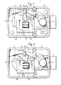
- Figure 1 shows the mechanism of an electronically-controlled safe lock, with its cap removed, in the locked condition;
- Figure 2 is a similar view of the mechanism of Figure 1, in the condition in which it has been freed for unlocking;
- Figure 3 is a similar view of the mechanism of Figures 1 and 2, in the unlocked condition; and
- Figure 4 is a sectional view, to an enlarged scale, through the electromechanical actuator of the mechanism of Figures 1 to 3.
- The lock shown in the drawings is intended principally for use in locking the main boltwork of a safe or vault door, and its layout and dimensions are chosen so that the unit may be interchangeable with known keyless combination locks, such as that marketed by the present applicants under the designation 7L08. It has a bolt 1 which can be extended and retracted from the
case 2 and to which a drop-arm 3 is pivoted at 4. Thearm 3 has a laterally-extendedhead 5 at its end opposite to its connection with the bolt, which in the normal locked condition of the mechanism illustrated in Figure 1 lies on the periphery of a rotatable disc 6, onto which it is drawn by a spring schematically indicated at 7. In this condition thehead 5 faces afixed abutment 8 in the lock case to resist forced retraction of the bolt 1. - The disc 6 is freely rotatable by hand through the agency of an external knob or handle (not shown), within limits set by a stop 9A, but is normally held lightly in the rest position shown in Figure 1 by means of a detent spring (not shown). It has a
notch 10 in its periphery which, when the disc is turned anti-clockwise (in the sense of the drawing) away from its rest position underlies thehead 5 of the drop-arm, and into which the head is biased to engage by thespring 7 so as to establish a drive connection between the disc 6 andbolt 5. Normally, however, thehead 5 is blocked from moving into full engagement with thenotch 10 and free of theabutment 8 by the presence of the actuatingmember 11 of a bistableelectromechanical actuator 12. Theactuator 12 is similar to the actuators shown in our copending United Kingdom patent application No. 2142374, comprising amagnetising coil 13 within which the actuatingmember 11 is pivoted, and a rectangular horseshoepermanent magnet 14 surrounding thecoil 13, with the actuating member extending through the gap between the poles of the permanent magnet. That part of the actuatingmember 11 which extends within thecoil 13 and between the associated permanent magnet poles is made from a magnetisable material having a low energy requirement for reversing its magnetic polarity coupled with a high remanence, such as a heat-treated element of the cobalt-iron-vanadium alloy marketed by Telcon Metals Limited under the name "Chromindur". - An example of the construction of an
actuator 12 for use in this lock mechanism is shown in Figure 4. Abar 11A (which may be laminated) of Chromindur is fitted at one end with aplastics cap 11B by which it is pivotally borne in a pair ofrecesses 13B formed inside thecoil bobbin 13A. Thebar 11A extends out of thebobbin 13A to lie between the poles P1 and P2 of theassociated field magnet 14 and its upper end is fitted with a plastics tip piece 11C. The actuator is assembled by passing the Chromindurbar 11A with itscap 11B through t he bottom of thecoil bobbin 13A and snapping ont eh tip piece 11C. The coil is then assembled to themagnet 14 which retains the actuating member against ejection through the bottom of the bobbin. - The actuating
member 11 can be flipped between two positions (as indicated by comparing its positions in Figures 1 and 2) in response to pulses of electricity passed through the associatedcoil 13 in opposite directions. For example, if it is assumed that the magnet pole P1 is a North and P2 a South, then if an electrical pulse is sent through the associatedcoil 13 in the direction such as to induce a North pole at the bottom end of theChromindur element 11A within the coil and a South pole at the top end of that element between the poles P1 and P2, then the element will be attracted by pole P1 and repelled by pole P2 so as to pivot the actuating member into the position in which it is shown in Figure 1, being its locking position. The remanence of theelement 11A is sufficient to keep the actuating member in that position until an electrical pulse is sent through thecoil 13 in the opposite direction, whereupon the induced polarity of theelement 11A is reversed so that its end between the poles P1 and P2 now becomes a North, and it will be influenced oppositely by the permanent magnet poles to pivot the actuating member into the position in which it is shown in Figure 2, being its release position. - In use, magnetising pulses are supplied to the
coil 13 from an electronic control circuit (not shown) associated with a code-input or recognition device such as a numeric keypad, dard-reader, biometric sensor or the like, so that thecoil 13 is pulsed to move the actuating member out of its Figure 1 position and into its Figure 2 position only when a correct code or other indication of the user's authority to operate the lock has been entered. A timing circuit may also be included to restrict possible operation of the actuator to its release position only to specified periods of the day. - Assuming that the actuator has been flipped to its release position, the disc 6 can now be turned to pick up the drop-
arm 3 as shown in Figure 2. Turning the disc further anti-clockwise (in the sense of the drawing) thereafter retracts the bolt 1 to the Figure 3 position, through the coupling established between the drop-arm head 5 andnotch 10. - The operation of the control circuit may provide for an unlocking "window" of limited duration following operation of the
actuator 12 to its release position, after which thecoil 13 will be automatically pulsed again to return themember 11 to its locking position (shown in dotted line in Figure 3), or a separate locking pulse may be given under user control. The bolt 1 can be thrown out again, (either before or after the actuator has been flipped back to its locking position), by turning the disc 6 clockwise to drive the drop-arm 3 rightwards through the engagement of itshead 5 in thenotch 10. In doing so, if the actuator has already been flipped back to its locking position thehead 5 will come up against the side of the actuatingmember 11 and displace it temporarily back to its release position, the mechanism passing through a condition equivalent to that shown in Figure 2 at this point. From this condition, continued clockwise rotation of the disc 6 will serve to throw out the drop-arm head 5 from thenotch 10 through the action of thecam surfaces head 5 rises clear of the end of the actuatingmember 11 the latter will flip back to its locking position by the interaction of its remanent magnetism with the field of thepermanent magnet 14. Otherwise, it will move back to its locking position when the subsequent locking pulse is given. It will be seen that the actuatingmember 11 is not loaded by the drop-arm in the normal locked condition of the mechani sm. - It has been mentioned that during the time between pulses through the
actuator coil 13, the last-induced polarity of themagnetisable element 11A is retained, so that this polarity serves effectively as a "memory" of the most recent command signal, i.e. "lock" or "release". The potential importance of this characteristic during the bolt-throwing sequence of the illustrated lock has already been explained. It is also of importance in the following circumstances. That is to say it may occur that at the time when a "release" command is given a user may have already turned the disc 6 from the Figure 1 position to align thenotch 10 with thehead 5, so that the drop-arm is resting on the actuatingmember 11 and the latter is prevented from moving at the instant when thecoil 13 is pulsed to reverse its polarity. However, the magnetic influence on the actuating member remains so that as soon thereafter as the disc 6 is turned again to lift the drop-arm slightly the actuator will flip over to its "release" position and the bolt 1 can be withdrawn, without any further energisation of thecoil 13.
Claims (6)
Applications Claiming Priority (2)
| Application Number | Priority Date | Filing Date | Title |
|---|---|---|---|
| GB868622120A GB8622120D0 (en) | 1986-09-13 | 1986-09-13 | Locking mechanisms |
| GB8622120 | 1986-09-13 |
Publications (2)
| Publication Number | Publication Date |
|---|---|
| EP0260860A1 true EP0260860A1 (en) | 1988-03-23 |
| EP0260860B1 EP0260860B1 (en) | 1991-01-23 |
Family
ID=10604174
Family Applications (1)
| Application Number | Title | Priority Date | Filing Date |
|---|---|---|---|
| EP87307911A Expired - Lifetime EP0260860B1 (en) | 1986-09-13 | 1987-09-08 | Locking mechanisms |
Country Status (4)
| Country | Link |
|---|---|
| EP (1) | EP0260860B1 (en) |
| AU (1) | AU7831387A (en) |
| DE (1) | DE3767622D1 (en) |
| GB (2) | GB8622120D0 (en) |
Cited By (9)
| Publication number | Priority date | Publication date | Assignee | Title |
|---|---|---|---|---|
| EP0451712A1 (en) * | 1990-04-11 | 1991-10-16 | Costruzioni Italiane Serrature Affini C.I.S.A. S.p.A. | Spring latch actuation device in locks operated by magnetic cards |
| FR2695425A1 (en) * | 1992-09-09 | 1994-03-11 | Caradonna Benito | Electromechanical combination lock mechanism - uses electrically operated cam to engage or disengage coupling between operating knob and bolt. |
| EP0777023A3 (en) * | 1992-01-13 | 1999-05-26 | C & M TECHNOLOGY, INC. | High security lock mechanism |
| WO2000068534A2 (en) * | 1999-05-06 | 2000-11-16 | Ilco Unican Inc. | Electromechanical lock |
| US6911897B2 (en) | 1988-09-29 | 2005-06-28 | C&M Technology, Inc. | Electronic combination lock with high security features |
| US8093986B2 (en) | 2009-01-20 | 2012-01-10 | Lock II, L.L.C. | Self-powered electronic lock |
| US8091392B2 (en) | 2008-09-05 | 2012-01-10 | Lock II, L.L.C. | High security lock |
| US8635893B2 (en) | 2008-09-05 | 2014-01-28 | Lock II, L.L.C. | High security lock |
| US9080349B2 (en) | 2012-12-19 | 2015-07-14 | Lock II, L.L.C. | Device and methods for preventing unwanted access to a locked enclosure |
Families Citing this family (6)
| Publication number | Priority date | Publication date | Assignee | Title |
|---|---|---|---|---|
| GB2206638B (en) * | 1987-05-22 | 1991-03-20 | Pickersgill Kaye Ltd | Electromechanical lock |
| DE3817696C1 (en) * | 1988-05-25 | 1989-11-30 | Pierre Dipl.-Ing. 8012 Ottobrunn De Meyers | Coupling system with driving plate, drop-in lever and detent element |
| DE8914508U1 (en) * | 1989-02-02 | 1990-06-13 | Dom-Sicherheitstechnik Gmbh & Co Kg, 5040 Bruehl, De | |
| GB9405701D0 (en) * | 1994-03-23 | 1994-05-11 | Intelligent Locking Sys Ltd | Improvements in or relating to locks |
| SE506763C2 (en) * | 1995-01-18 | 1998-02-09 | Assa Ab | Locks |
| GB0031060D0 (en) | 2000-12-20 | 2001-01-31 | Meritor Light Vehicle Sys Ltd | Latch arrangement |
Citations (2)
| Publication number | Priority date | Publication date | Assignee | Title |
|---|---|---|---|---|
| FR2225601B1 (en) * | 1973-04-13 | 1978-03-24 | Daempa As | |
| CH606717A5 (en) * | 1976-07-07 | 1978-11-15 | Steurer Hans Fertigbautechnik | Coin operated door lock |
Family Cites Families (6)
| Publication number | Priority date | Publication date | Assignee | Title |
|---|---|---|---|---|
| GB335570A (en) * | 1929-06-21 | 1930-09-22 | Ernest Cecil Gorman | Improvements in automatic means for controlling hand-operated locks of railway carriage doors and the like |
| US4073527A (en) * | 1977-01-12 | 1978-02-14 | Schlage Lock Company | Electrically controlled door lock |
| FR2558202B1 (en) * | 1984-01-12 | 1986-04-11 | Guitard Robert | ELECTROMECHANICAL LOCK |
| GB8418311D0 (en) * | 1984-07-18 | 1984-08-22 | Chubb Lips Nederland Bv | Locks |
| SE442420B (en) * | 1984-08-01 | 1985-12-23 | Wso Cpu System Ab | LAS |
| JPS6141762U (en) * | 1984-08-21 | 1986-03-17 | 俊彦 山下 | lock |
-
1986
- 1986-09-13 GB GB868622120A patent/GB8622120D0/en active Pending
-
1987
- 1987-09-08 DE DE8787307911T patent/DE3767622D1/en not_active Expired - Fee Related
- 1987-09-08 EP EP87307911A patent/EP0260860B1/en not_active Expired - Lifetime
- 1987-09-08 GB GB8721098A patent/GB2196378B/en not_active Expired - Fee Related
- 1987-09-11 AU AU78313/87A patent/AU7831387A/en not_active Abandoned
Patent Citations (2)
| Publication number | Priority date | Publication date | Assignee | Title |
|---|---|---|---|---|
| FR2225601B1 (en) * | 1973-04-13 | 1978-03-24 | Daempa As | |
| CH606717A5 (en) * | 1976-07-07 | 1978-11-15 | Steurer Hans Fertigbautechnik | Coin operated door lock |
Cited By (24)
| Publication number | Priority date | Publication date | Assignee | Title |
|---|---|---|---|---|
| US6911897B2 (en) | 1988-09-29 | 2005-06-28 | C&M Technology, Inc. | Electronic combination lock with high security features |
| EP0451712A1 (en) * | 1990-04-11 | 1991-10-16 | Costruzioni Italiane Serrature Affini C.I.S.A. S.p.A. | Spring latch actuation device in locks operated by magnetic cards |
| US7263865B2 (en) | 1992-01-13 | 2007-09-04 | C&M Technology, Inc. | High security lock mechanism |
| EP1213420A3 (en) * | 1992-01-13 | 2006-04-12 | C & M TECHNOLOGY, INC. | High security lock mechanism |
| EP0777023A3 (en) * | 1992-01-13 | 1999-05-26 | C & M TECHNOLOGY, INC. | High security lock mechanism |
| US6314773B1 (en) | 1992-01-13 | 2001-11-13 | C&M Technology, Inc. | High security lock mechanism |
| EP1213420A2 (en) * | 1992-01-13 | 2002-06-12 | C & M TECHNOLOGY, INC. | High security lock mechanism |
| US6502438B1 (en) * | 1992-01-13 | 2003-01-07 | C&M Technology, Inc. | Electronic combination lock having anti-tampering features |
| US6546769B2 (en) | 1992-01-13 | 2003-04-15 | C&M Technology, Inc. | High security lock mechanism |
| US5960655A (en) * | 1992-01-13 | 1999-10-05 | C&M Technology, Inc. | High security lock mechanism |
| FR2695425A1 (en) * | 1992-09-09 | 1994-03-11 | Caradonna Benito | Electromechanical combination lock mechanism - uses electrically operated cam to engage or disengage coupling between operating knob and bolt. |
| WO2000068534A2 (en) * | 1999-05-06 | 2000-11-16 | Ilco Unican Inc. | Electromechanical lock |
| WO2000068534A3 (en) * | 1999-05-06 | 2001-03-08 | Ilco Unican Inc | Electromechanical lock |
| US8091392B2 (en) | 2008-09-05 | 2012-01-10 | Lock II, L.L.C. | High security lock |
| US8516863B2 (en) | 2008-09-05 | 2013-08-27 | Lock II, L.L.C. | High security lock |
| US8635893B2 (en) | 2008-09-05 | 2014-01-28 | Lock II, L.L.C. | High security lock |
| US8093986B2 (en) | 2009-01-20 | 2012-01-10 | Lock II, L.L.C. | Self-powered electronic lock |
| US11613911B2 (en) | 2012-12-19 | 2023-03-28 | Lock Ii, Llc | Device and methods for preventing unwanted access to a locked enclosure |
| US9080349B2 (en) | 2012-12-19 | 2015-07-14 | Lock II, L.L.C. | Device and methods for preventing unwanted access to a locked enclosure |
| US9816294B2 (en) | 2012-12-19 | 2017-11-14 | Lock Ii, Llc | Device and methods for preventing unwanted access to a locked enclosure |
| US10190335B2 (en) | 2012-12-19 | 2019-01-29 | Lock Ii, Llc | Methods for preventing unwanted access to a locked enclosure |
| US10550604B2 (en) | 2012-12-19 | 2020-02-04 | Lock Ii, Llc | Device and methods for preventing unwanted access to a locked enclosure |
| US10557285B2 (en) | 2012-12-19 | 2020-02-11 | Lock Ii, Llc | Device and methods for preventing unwanted access to a locked enclosure |
| US11499342B2 (en) | 2012-12-19 | 2022-11-15 | Lock Ii, Llc | Device and methods for preventing unwanted access to a locked enclosure |
Also Published As
| Publication number | Publication date |
|---|---|
| GB8721098D0 (en) | 1987-10-14 |
| AU7831387A (en) | 1988-03-17 |
| GB8622120D0 (en) | 1986-10-22 |
| GB2196378B (en) | 1990-05-16 |
| GB2196378A (en) | 1988-04-27 |
| DE3767622D1 (en) | 1991-02-28 |
| EP0260860B1 (en) | 1991-01-23 |
Similar Documents
| Publication | Publication Date | Title |
|---|---|---|
| US6178791B1 (en) | Electronic reset for solenoid activated control in an electronic lock | |
| EP0260860A1 (en) | Locking mechanisms | |
| US4656850A (en) | Electric lock | |
| US4736970A (en) | Electrically controlled door lock | |
| JP2544467B2 (en) | Mechatronics closure device | |
| US5893283A (en) | Solenoid controlled bolt control for an electronic lock | |
| US4433355A (en) | Electronic locks for doors | |
| US4916927A (en) | Lock and method of securing and releasing a member | |
| US5029912A (en) | Locking device | |
| US4802353A (en) | Battery-powered door lock assembly and method | |
| JP4731912B2 (en) | Locking device | |
| US20040055346A1 (en) | Manipulationproof electromagnet arrangement, an electronic locking cylinder and a method for preventing manipulation of an electromagnet arrangment | |
| US4754625A (en) | Electrically controlled lock | |
| US4810014A (en) | Motor driven lock control | |
| US5000018A (en) | Hardware, in particular for doors or the like | |
| US6229421B1 (en) | Autosecuring solenoid | |
| US4908605A (en) | Device for confirming whether a lock is locked or unlocked | |
| US5684457A (en) | Tamper indication system for combination locks | |
| EP2975201B1 (en) | A locking device | |
| DK160623B (en) | DEVICE FOR ELECTROMAGNETIC FIXING TO A LOAD CYLINDER IN A MECHANICAL / ELECTRONIC LOADING SYSTEM | |
| EP0333821B1 (en) | Electrically controlled locks | |
| EP0125813A2 (en) | Locking mechanisms | |
| GB2278394A (en) | Electrically operated door lock | |
| JPH1068254A (en) | Electromagnetically operated lock | |
| GB1452032A (en) | Locks |
Legal Events
| Date | Code | Title | Description |
|---|---|---|---|
| PUAI | Public reference made under article 153(3) epc to a published international application that has entered the european phase |
Free format text: ORIGINAL CODE: 0009012 |
|
| AK | Designated contracting states |
Kind code of ref document: A1 Designated state(s): BE DE FR IT NL |
|
| 17P | Request for examination filed |
Effective date: 19880920 |
|
| 17Q | First examination report despatched |
Effective date: 19890622 |
|
| RAP1 | Party data changed (applicant data changed or rights of an application transferred) |
Owner name: CHUBB & SON'S LOCK AND SAFE COMPANY LIMITED |
|
| GRAA | (expected) grant |
Free format text: ORIGINAL CODE: 0009210 |
|
| AK | Designated contracting states |
Kind code of ref document: B1 Designated state(s): BE DE FR IT NL |
|
| PG25 | Lapsed in a contracting state [announced via postgrant information from national office to epo] |
Ref country code: IT Free format text: LAPSE BECAUSE OF FAILURE TO SUBMIT A TRANSLATION OF THE DESCRIPTION OR TO PAY THE FEE WITHIN THE PRE;WARNING: LAPSES OF ITALIAN PATENTS WITH EFFECTIVE DATE BEFORE 2007 MAY HAVE OCCURRED AT ANY TIME BEFORE 2007. THE CORRECT EFFECTIVE DATE MAY BE DIFFERENT FROM THE ONE RECORDED.SCRIBED TIME-LIMIT Effective date: 19910123 Ref country code: NL Effective date: 19910123 |
|
| ET | Fr: translation filed | ||
| REF | Corresponds to: |
Ref document number: 3767622 Country of ref document: DE Date of ref document: 19910228 |
|
| NLV1 | Nl: lapsed or annulled due to failure to fulfill the requirements of art. 29p and 29m of the patents act | ||
| PGFP | Annual fee paid to national office [announced via postgrant information from national office to epo] |
Ref country code: DE Payment date: 19911106 Year of fee payment: 5 |
|
| PLBE | No opposition filed within time limit |
Free format text: ORIGINAL CODE: 0009261 |
|
| STAA | Information on the status of an ep patent application or granted ep patent |
Free format text: STATUS: NO OPPOSITION FILED WITHIN TIME LIMIT |
|
| 26N | No opposition filed | ||
| PGFP | Annual fee paid to national office [announced via postgrant information from national office to epo] |
Ref country code: BE Payment date: 19920903 Year of fee payment: 6 |
|
| PGFP | Annual fee paid to national office [announced via postgrant information from national office to epo] |
Ref country code: FR Payment date: 19920916 Year of fee payment: 6 |
|
| PG25 | Lapsed in a contracting state [announced via postgrant information from national office to epo] |
Ref country code: DE Effective date: 19930602 |
|
| PG25 | Lapsed in a contracting state [announced via postgrant information from national office to epo] |
Ref country code: BE Effective date: 19930930 |
|
| BERE | Be: lapsed |
Owner name: CHUBB & SON'S LOCK AND SAFE CY LTD Effective date: 19930930 |
|
| PG25 | Lapsed in a contracting state [announced via postgrant information from national office to epo] |
Ref country code: FR Free format text: LAPSE BECAUSE OF NON-PAYMENT OF DUE FEES Effective date: 19940531 |
|
| REG | Reference to a national code |
Ref country code: FR Ref legal event code: ST |